JP4880947B2 - Driving force transmission device - Google Patents
Driving force transmission device Download PDFInfo
- Publication number
- JP4880947B2 JP4880947B2 JP2005248894A JP2005248894A JP4880947B2 JP 4880947 B2 JP4880947 B2 JP 4880947B2 JP 2005248894 A JP2005248894 A JP 2005248894A JP 2005248894 A JP2005248894 A JP 2005248894A JP 4880947 B2 JP4880947 B2 JP 4880947B2
- Authority
- JP
- Japan
- Prior art keywords
- driving force
- force transmission
- transmission device
- sliding surface
- sliding
- Prior art date
- Legal status (The legal status is an assumption and is not a legal conclusion. Google has not performed a legal analysis and makes no representation as to the accuracy of the status listed.)
- Active
Links
- 230000005540 biological transmission Effects 0.000 title claims description 92
- OKTJSMMVPCPJKN-UHFFFAOYSA-N Carbon Chemical compound [C] OKTJSMMVPCPJKN-UHFFFAOYSA-N 0.000 claims description 5
- 229910052799 carbon Inorganic materials 0.000 claims description 5
- 239000010687 lubricating oil Substances 0.000 claims description 4
- 230000008859 change Effects 0.000 description 18
- 230000007246 mechanism Effects 0.000 description 12
- 230000007774 longterm Effects 0.000 description 6
- 230000002093 peripheral effect Effects 0.000 description 6
- 239000003921 oil Substances 0.000 description 5
- 238000010586 diagram Methods 0.000 description 4
- 230000000694 effects Effects 0.000 description 4
- 230000004907 flux Effects 0.000 description 3
- 229910052710 silicon Inorganic materials 0.000 description 3
- 239000010703 silicon Substances 0.000 description 3
- XEEYBQQBJWHFJM-UHFFFAOYSA-N Iron Chemical compound [Fe] XEEYBQQBJWHFJM-UHFFFAOYSA-N 0.000 description 2
- 238000005299 abrasion Methods 0.000 description 2
- 230000001788 irregular Effects 0.000 description 2
- 239000002184 metal Substances 0.000 description 2
- 229910052751 metal Inorganic materials 0.000 description 2
- 238000000034 method Methods 0.000 description 2
- 230000009467 reduction Effects 0.000 description 2
- 230000036962 time dependent Effects 0.000 description 2
- 230000009471 action Effects 0.000 description 1
- 230000001154 acute effect Effects 0.000 description 1
- 238000013459 approach Methods 0.000 description 1
- 230000008901 benefit Effects 0.000 description 1
- 230000015572 biosynthetic process Effects 0.000 description 1
- 239000011248 coating agent Substances 0.000 description 1
- 238000000576 coating method Methods 0.000 description 1
- 230000003247 decreasing effect Effects 0.000 description 1
- 238000007599 discharging Methods 0.000 description 1
- 229910052742 iron Inorganic materials 0.000 description 1
- 239000000463 material Substances 0.000 description 1
- 238000003825 pressing Methods 0.000 description 1
- 230000008569 process Effects 0.000 description 1
Images


Classifications
-
- F—MECHANICAL ENGINEERING; LIGHTING; HEATING; WEAPONS; BLASTING
- F16—ENGINEERING ELEMENTS AND UNITS; GENERAL MEASURES FOR PRODUCING AND MAINTAINING EFFECTIVE FUNCTIONING OF MACHINES OR INSTALLATIONS; THERMAL INSULATION IN GENERAL
- F16D—COUPLINGS FOR TRANSMITTING ROTATION; CLUTCHES; BRAKES
- F16D13/00—Friction clutches
- F16D13/58—Details
- F16D13/60—Clutching elements
- F16D13/64—Clutch-plates; Clutch-lamellae
-
- F—MECHANICAL ENGINEERING; LIGHTING; HEATING; WEAPONS; BLASTING
- F16—ENGINEERING ELEMENTS AND UNITS; GENERAL MEASURES FOR PRODUCING AND MAINTAINING EFFECTIVE FUNCTIONING OF MACHINES OR INSTALLATIONS; THERMAL INSULATION IN GENERAL
- F16D—COUPLINGS FOR TRANSMITTING ROTATION; CLUTCHES; BRAKES
- F16D13/00—Friction clutches
- F16D13/22—Friction clutches with axially-movable clutching members
- F16D13/38—Friction clutches with axially-movable clutching members with flat clutching surfaces, e.g. discs
- F16D13/52—Clutches with multiple lamellae ; Clutches in which three or more axially moveable members are fixed alternately to the shafts to be coupled and are pressed from one side towards an axially-located member
-
- F—MECHANICAL ENGINEERING; LIGHTING; HEATING; WEAPONS; BLASTING
- F16—ENGINEERING ELEMENTS AND UNITS; GENERAL MEASURES FOR PRODUCING AND MAINTAINING EFFECTIVE FUNCTIONING OF MACHINES OR INSTALLATIONS; THERMAL INSULATION IN GENERAL
- F16D—COUPLINGS FOR TRANSMITTING ROTATION; CLUTCHES; BRAKES
- F16D13/00—Friction clutches
- F16D13/58—Details
- F16D13/60—Clutching elements
- F16D13/64—Clutch-plates; Clutch-lamellae
- F16D13/648—Clutch-plates; Clutch-lamellae for clutches with multiple lamellae
-
- F—MECHANICAL ENGINEERING; LIGHTING; HEATING; WEAPONS; BLASTING
- F16—ENGINEERING ELEMENTS AND UNITS; GENERAL MEASURES FOR PRODUCING AND MAINTAINING EFFECTIVE FUNCTIONING OF MACHINES OR INSTALLATIONS; THERMAL INSULATION IN GENERAL
- F16D—COUPLINGS FOR TRANSMITTING ROTATION; CLUTCHES; BRAKES
- F16D13/00—Friction clutches
- F16D13/58—Details
- F16D13/74—Features relating to lubrication
-
- F—MECHANICAL ENGINEERING; LIGHTING; HEATING; WEAPONS; BLASTING
- F16—ENGINEERING ELEMENTS AND UNITS; GENERAL MEASURES FOR PRODUCING AND MAINTAINING EFFECTIVE FUNCTIONING OF MACHINES OR INSTALLATIONS; THERMAL INSULATION IN GENERAL
- F16D—COUPLINGS FOR TRANSMITTING ROTATION; CLUTCHES; BRAKES
- F16D27/00—Magnetically- or electrically- actuated clutches; Control or electric circuits therefor
- F16D27/10—Magnetically- or electrically- actuated clutches; Control or electric circuits therefor with an electromagnet not rotating with a clutching member, i.e. without collecting rings
- F16D27/108—Magnetically- or electrically- actuated clutches; Control or electric circuits therefor with an electromagnet not rotating with a clutching member, i.e. without collecting rings with axially movable clutching members
- F16D27/112—Magnetically- or electrically- actuated clutches; Control or electric circuits therefor with an electromagnet not rotating with a clutching member, i.e. without collecting rings with axially movable clutching members with flat friction surfaces, e.g. discs
- F16D27/115—Magnetically- or electrically- actuated clutches; Control or electric circuits therefor with an electromagnet not rotating with a clutching member, i.e. without collecting rings with axially movable clutching members with flat friction surfaces, e.g. discs with more than two discs, e.g. multiple lamellae
-
- F—MECHANICAL ENGINEERING; LIGHTING; HEATING; WEAPONS; BLASTING
- F16—ENGINEERING ELEMENTS AND UNITS; GENERAL MEASURES FOR PRODUCING AND MAINTAINING EFFECTIVE FUNCTIONING OF MACHINES OR INSTALLATIONS; THERMAL INSULATION IN GENERAL
- F16D—COUPLINGS FOR TRANSMITTING ROTATION; CLUTCHES; BRAKES
- F16D27/00—Magnetically- or electrically- actuated clutches; Control or electric circuits therefor
- F16D2027/008—Details relating to the magnetic circuit, or to the shape of the clutch parts to achieve a certain magnetic path
-
- F—MECHANICAL ENGINEERING; LIGHTING; HEATING; WEAPONS; BLASTING
- F16—ENGINEERING ELEMENTS AND UNITS; GENERAL MEASURES FOR PRODUCING AND MAINTAINING EFFECTIVE FUNCTIONING OF MACHINES OR INSTALLATIONS; THERMAL INSULATION IN GENERAL
- F16D—COUPLINGS FOR TRANSMITTING ROTATION; CLUTCHES; BRAKES
- F16D65/00—Parts or details
- F16D65/02—Braking members; Mounting thereof
- F16D2065/13—Parts or details of discs or drums
- F16D2065/1304—Structure
- F16D2065/132—Structure layered
-
- F—MECHANICAL ENGINEERING; LIGHTING; HEATING; WEAPONS; BLASTING
- F16—ENGINEERING ELEMENTS AND UNITS; GENERAL MEASURES FOR PRODUCING AND MAINTAINING EFFECTIVE FUNCTIONING OF MACHINES OR INSTALLATIONS; THERMAL INSULATION IN GENERAL
- F16D—COUPLINGS FOR TRANSMITTING ROTATION; CLUTCHES; BRAKES
- F16D69/00—Friction linings; Attachment thereof; Selection of coacting friction substances or surfaces
- F16D2069/004—Profiled friction surfaces, e.g. grooves, dimples
-
- F—MECHANICAL ENGINEERING; LIGHTING; HEATING; WEAPONS; BLASTING
- F16—ENGINEERING ELEMENTS AND UNITS; GENERAL MEASURES FOR PRODUCING AND MAINTAINING EFFECTIVE FUNCTIONING OF MACHINES OR INSTALLATIONS; THERMAL INSULATION IN GENERAL
- F16D—COUPLINGS FOR TRANSMITTING ROTATION; CLUTCHES; BRAKES
- F16D2200/00—Materials; Production methods therefor
- F16D2200/0004—Materials; Production methods therefor metallic
- F16D2200/0008—Ferro
-
- F—MECHANICAL ENGINEERING; LIGHTING; HEATING; WEAPONS; BLASTING
- F16—ENGINEERING ELEMENTS AND UNITS; GENERAL MEASURES FOR PRODUCING AND MAINTAINING EFFECTIVE FUNCTIONING OF MACHINES OR INSTALLATIONS; THERMAL INSULATION IN GENERAL
- F16D—COUPLINGS FOR TRANSMITTING ROTATION; CLUTCHES; BRAKES
- F16D2200/00—Materials; Production methods therefor
- F16D2200/0034—Materials; Production methods therefor non-metallic
- F16D2200/0039—Ceramics
-
- F—MECHANICAL ENGINEERING; LIGHTING; HEATING; WEAPONS; BLASTING
- F16—ENGINEERING ELEMENTS AND UNITS; GENERAL MEASURES FOR PRODUCING AND MAINTAINING EFFECTIVE FUNCTIONING OF MACHINES OR INSTALLATIONS; THERMAL INSULATION IN GENERAL
- F16D—COUPLINGS FOR TRANSMITTING ROTATION; CLUTCHES; BRAKES
- F16D2200/00—Materials; Production methods therefor
- F16D2200/0034—Materials; Production methods therefor non-metallic
- F16D2200/0052—Carbon
-
- F—MECHANICAL ENGINEERING; LIGHTING; HEATING; WEAPONS; BLASTING
- F16—ENGINEERING ELEMENTS AND UNITS; GENERAL MEASURES FOR PRODUCING AND MAINTAINING EFFECTIVE FUNCTIONING OF MACHINES OR INSTALLATIONS; THERMAL INSULATION IN GENERAL
- F16D—COUPLINGS FOR TRANSMITTING ROTATION; CLUTCHES; BRAKES
- F16D2300/00—Special features for couplings or clutches
- F16D2300/10—Surface characteristics; Details related to material surfaces
-
- F—MECHANICAL ENGINEERING; LIGHTING; HEATING; WEAPONS; BLASTING
- F16—ENGINEERING ELEMENTS AND UNITS; GENERAL MEASURES FOR PRODUCING AND MAINTAINING EFFECTIVE FUNCTIONING OF MACHINES OR INSTALLATIONS; THERMAL INSULATION IN GENERAL
- F16D—COUPLINGS FOR TRANSMITTING ROTATION; CLUTCHES; BRAKES
- F16D27/00—Magnetically- or electrically- actuated clutches; Control or electric circuits therefor
- F16D27/004—Magnetically- or electrically- actuated clutches; Control or electric circuits therefor with permanent magnets combined with electromagnets
Landscapes
- Engineering & Computer Science (AREA)
- General Engineering & Computer Science (AREA)
- Mechanical Engineering (AREA)
- Physics & Mathematics (AREA)
- Electromagnetism (AREA)
- Mechanical Operated Clutches (AREA)
Description
本発明は、相対回転可能に同軸配置された駆動力伝達部材間の摩擦係合により駆動力を伝達する駆動力伝達装置に関するものである。 The present invention relates to a driving force transmission device that transmits a driving force by frictional engagement between driving force transmission members arranged coaxially so as to be relatively rotatable.
従来、上記のような駆動力伝達装置には、駆動力伝達特性の向上を図るべく駆動力伝達部材の摺動面に複数の微細溝を形成したものがある。例えば、特許文献1に記載の駆動力伝達装置では、駆動力伝達部材を構成する駆動側又は従動側クラッチプレートの一方に、その摺動面の周方向に沿って並列に延びる複数の微細溝が形成されている。即ち、一方の摺動面に微細溝を形成することで、駆動側及び摺動側の両摺動面間に形成される油膜、詳しくはその膜厚を適切に維持することができる。そして、これにより、そのμ−v特性を滑り速度vが大となるほど摩擦係数μが大となる高摩擦正勾配として、耐ジャダー性に優れる良好な駆動力伝達特性を確保することができる。
上記のような駆動力伝達装置における摺動面は、装置の寿命として想定される使用時間を経過した時点でも良好な駆動力伝達特性を維持しなければならない。即ち、長時間に渡る使用により摺動面が磨耗しても適切な微細溝が維持され、摺動面における油膜の状態が良好に保たれる必要がある。一方、上記のような微細溝は、その断面形状が矩形となるのが理想であるが、現実的には矩形の微細な溝を形成するのは困難であり、一般的にはその溝幅が開口部から底部に近づくに従って狭くなる断面略三角形状となる。そして、特に上記従来例のごとく切削加工により形成されたものについては、その三角形状がより鋭角なものとなる。このため、長期使用時においては、その摺動面の磨耗により微細溝の溝幅が次第に狭くなり、これに伴いその駆動力伝達特性が変動してしまう。そこで、従来は、上記のような長期使用に伴う磨耗を考慮して、その磨耗後においても必要な溝幅が残るように予め微細溝の開口端の溝幅を広くし、且つ、その溝深さを深く設定することが必要である。このため、従来の駆動力伝達装置では、使用初期における微細溝が形成された側の摺動面の摺接領域(溝部を除く領域)の割合は約50%若しくはそれ以下とされていた。 The sliding surface in the driving force transmission device as described above must maintain a good driving force transmission characteristic even when the usage time assumed as the lifetime of the device has elapsed. That is, it is necessary to maintain an appropriate fine groove even when the sliding surface is worn due to use over a long period of time, and to maintain a good oil film state on the sliding surface. On the other hand, it is ideal that the cross-sectional shape of the fine groove as described above is rectangular, but in reality it is difficult to form a rectangular fine groove. It becomes a substantially triangular cross section that becomes narrower as it approaches the bottom from the opening. And especially about what was formed by cutting like the said prior art example, the triangular shape will become a more acute angle. For this reason, during long-term use, the groove width of the fine groove gradually becomes narrow due to wear of the sliding surface, and the driving force transmission characteristics fluctuate accordingly. Therefore, conventionally, in consideration of the wear associated with long-term use as described above, the groove width at the opening end of the fine groove is widened in advance so that the necessary groove width remains after the wear, and the groove depth. It is necessary to set the depth deeply. For this reason, in the conventional driving force transmission device, the ratio of the sliding contact area (area excluding the groove portion) of the sliding surface on the side where the fine groove is formed in the initial stage of use is about 50% or less.
しかし、開口端の溝幅を広くする構成では、特に使用初期において摺動面の摺接領域が狭く、面圧が高くなることから、摺動面の磨耗による微細溝の溝幅の減少が顕著となり、
使用初期と長期使用後では駆動力伝達特性が大きく変動してしまう。
However, in the configuration in which the groove width at the opening end is widened, the sliding contact area of the sliding surface is narrow and the surface pressure becomes high particularly in the initial use, and therefore the reduction in the groove width of the fine groove due to wear of the sliding surface is remarkable. And
The driving force transmission characteristics greatly fluctuate between the initial use and after long-term use.
本発明は、上記問題点を解決するためになされたものであって、その目的は、長期に渡りその良好なる駆動力伝達特性を維持することのできる駆動力伝達を提供することにある。 The present invention has been made to solve the above problems, and an object of the present invention is to provide a driving force transmission capable of maintaining a good driving force transmission characteristic over a long period of time.
上記問題点を解決するために、請求項1に記載の発明は、相対回転可能に同軸配置された第1及び第2駆動力伝達部材間の潤滑油を介在させた摩擦係合により駆動力を伝達する駆動力伝達装置であって、第1駆動力伝達部材の摺動面にはダイヤモンド状炭素被膜が形成されるとともに、第2駆動力伝達部材の摺動面には微細溝が形成され、使用初期における前記微細溝は、溝深さが15μm以下に形成されるとともに、前記第2駆動力伝達部材の摺動面の表面における溝幅の平均値が15〜45μmであり、且つ前記摺動面の表面からの深さ1.5μmにおける溝幅の平均値もまた15〜45μmであり、使用初期における前記第2駆動力伝達部材の摺動面の摺接領域の割合が55〜90%であり、前記第2駆動力伝達部材の摺動面が使用初期の状態から1.5μm磨耗した状態における摺接領域の割合が55〜90%であること、を要旨とする。 In order to solve the above-mentioned problems, the invention according to claim 1 is characterized in that the driving force is generated by friction engagement between the first and second driving force transmitting members arranged coaxially so as to be relatively rotatable. A driving force transmission device for transmitting, wherein a diamond-like carbon film is formed on the sliding surface of the first driving force transmission member, and a fine groove is formed on the sliding surface of the second driving force transmission member, The fine groove in the initial stage of use is formed with a groove depth of 15 μm or less, an average value of the groove width on the surface of the sliding surface of the second driving force transmission member is 15 to 45 μm, and the sliding The average value of the groove width at a depth of 1.5 μm from the surface of the surface is also 15 to 45 μm, and the ratio of the sliding contact area of the sliding surface of the second driving force transmission member in the initial use is 55 to 90%. Ah is, the sliding surface of the second driving force transmitting member is used initial Proportion of sliding contact area from the state in the state of 1.5μm wear is 55 to 90% and the gist.
上記構成によれば、第1駆動力伝達部材の摺動面に形成されたダイヤモンド状炭素被膜により第2駆動力伝達部材の摺動面の磨耗が抑えられる。また、第2駆動力伝達部材の摺動面の摺接領域の割合が従来よりも高いので、第2駆動力伝達部材の摺動面の磨耗をさらに抑えることができる。従って、駆動力伝達特性の経時変化を抑制することできる。加えて、長期使用後でも微細溝の溝幅が適切に保たれ、余剰な油膜を切る効果が維持される。また、その溝深さを15μm以下に抑えることで、微細溝の形成時における余肉の流動を抑えることができ、従来よりも矩形に近い理想的な断面形状の微細溝を形成することができる。その結果、駆動力伝達特性の変化を抑えて長期に渡りその良好な駆動力伝達特性を維持することができるとともに、より確実に使用初期と長期使用後の駆動力伝達特性の変動を抑えることができる。 According to the above configuration, wear of the sliding surface of the second driving force transmission member is suppressed by the diamond-like carbon film formed on the sliding surface of the first driving force transmission member. Moreover, since the ratio of the sliding contact area | region of the sliding surface of a 2nd driving force transmission member is higher than before, abrasion of the sliding surface of a 2nd driving force transmission member can further be suppressed. Accordingly, it is possible to suppress changes with time in the driving force transmission characteristics. In addition, the groove width of the fine groove is properly maintained even after long-term use, and the effect of cutting excess oil film is maintained. Further, by suppressing the groove depth to 15 μm or less, it is possible to suppress surplus flow during formation of the fine groove, and it is possible to form a fine groove having an ideal cross-sectional shape closer to a rectangle than in the past. . As a result, it is possible to suppress changes in driving force transmission characteristics and maintain good driving force transmission characteristics over a long period of time, and more reliably suppress fluctuations in driving force transmission characteristics after the initial use and after long-term use. it can.
請求項2に記載の発明は、前記微細溝は、プレス加工により形成されてなること、を要旨とする。
上記構成によれば、比較的容易に上記請求項1に記載の形状を有する微細溝を形成することができる。加えて、切削加工により微細溝を形成した場合には、該微細溝の両側端に突条が形成されるが、こうした突条は磨耗しやすいことから、その磨耗前と磨耗後とで駆動力伝達特性が大きく変化することになる。この点、プレス加工により形成した場合には、このような突条が比較的形成され難い。従って、上記構成によれば、その駆動力伝達特性の変化をより小さく抑えることができる。
The gist of the invention described in claim 2 is that the fine groove is formed by press working.
According to the said structure, the fine groove | channel which has the shape of the said Claim 1 can be formed comparatively easily. In addition, when fine grooves are formed by cutting, ridges are formed on both ends of the fine grooves. Since these ridges are easily worn, the driving force before and after the wear is increased. The transfer characteristics will change greatly. In this respect, when formed by press working, such protrusions are relatively difficult to form. Therefore, according to the above configuration, the change in the driving force transmission characteristic can be further suppressed.
請求項3に記載の発明は、前記微細溝は、前記相対回転の回転軸心を中心とする円周方向に形成されてなること、を要旨とする。
上記構成によれば、摺動方向(回転方向)において余剰な油膜を切る効果がさらに良好となり、境界摩擦を維持しμ−v特性を正勾配として、より良好な駆動力伝達特性を確保することができる。
The gist of the invention described in
According to the above configuration, the effect of cutting the excess oil film in the sliding direction (rotation direction) is further improved, maintaining the boundary friction and making the μ-v characteristic a positive gradient to ensure better driving force transmission characteristics. Can do.
請求項4に記載の発明は、前記第1及び第2駆動力伝達部材は、これらの摺動面を通過して形成される磁路による電磁力によって押圧されること、を要旨とする。
上記構成によれば、摺動面の摺接領域の割合が従来よりも高いので、前記第1及び第2駆動力伝達部材を押圧するための電磁力の磁気抵抗が小さくなるとともに、磁気抵抗の経時変化を抑えることができ、長期に渡り伝達トルクの良好な制御性を維持できる。
The gist of the invention described in
According to the above configuration, since the ratio of the sliding contact area of the sliding surface is higher than the conventional one, the magnetic resistance of the electromagnetic force for pressing the first and second driving force transmission members is reduced and the magnetic resistance is reduced. A change with time can be suppressed, and good controllability of the transmission torque can be maintained over a long period of time.
本発明によれば、駆動力伝達部材の摺動面の磨耗を抑え、駆動力伝達特性の経時変化を抑制することの可能な駆動力伝達を提供することができる。 ADVANTAGE OF THE INVENTION According to this invention, the driving force transmission which can suppress the abrasion of the sliding surface of a driving force transmission member and can suppress a time-dependent change of a driving force transmission characteristic can be provided.
以下、本発明を四輪駆動車の駆動力伝達装置に具体化した一実施形態を図面に従って説明する。
図1は、駆動力伝達装置の概略構成図、そして、図2は、駆動力伝達装置を備えた車両(四輪駆動車)の概略構成図である。
Hereinafter, an embodiment in which the present invention is embodied in a driving force transmission device for a four-wheel drive vehicle will be described with reference to the drawings.
FIG. 1 is a schematic configuration diagram of a driving force transmission device, and FIG. 2 is a schematic configuration diagram of a vehicle (four-wheel drive vehicle) provided with the driving force transmission device.
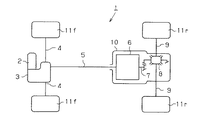
図2に示すように、車両1は、前輪駆動車をベースとする四輪駆動車であり、エンジン2の片側に組み付けられたトランスアクスル3には、一対のフロントアクスル4が連結されている。また、トランスアクスル3には、上記各フロントアクスル4とともにプロペラシャフト5が連結されており、該プロペラシャフト5は、駆動力伝達装置6を介してピニオンシャフト(ドライブピニオンシャフト)7と連結されている。そして、ピニオンシャフト7は、ディファレンシャル装置としてのリヤディファレンシャル8を介して一対のリヤアクスル9と連結されている。尚、本実施形態では、駆動力伝達装置6、ピニオンシャフト7、及びリヤディファレンシャル8は、ディファレンシャルキャリヤ10内に収容されている。
As shown in FIG. 2, the vehicle 1 is a four-wheel drive vehicle based on a front wheel drive vehicle, and a pair of
即ち、エンジン2の駆動力は、上記フロントアクスル4を介して前輪11fに伝達される。そして、駆動力伝達装置6によりプロペラシャフト5とピニオンシャフト7とがトルク伝達可能に連結された場合には、エンジン2の駆動力がピニオンシャフト7からリヤディファレンシャル8及び各リヤアクスル9を介して後輪11rに伝達されるようになっている。
That is, the driving force of the engine 2 is transmitted to the
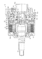
次に、本実施形態の駆動力伝達装置について説明する。
図1に示すように、本実施形態の駆動力伝達装置6は、プロペラシャフト5に連結されるフロントハウジング12、ピニオンシャフト7に連結されるインナシャフト13、及びこれらフロントハウジング12とインナシャフト13との間に配置されたメインクラッチ14を備えている。
Next, the driving force transmission device of this embodiment will be described.
As shown in FIG. 1, the driving
詳述すると、本実施形態では、フロントハウジング12は、有底筒状に形成されており、その底部12aには、プロペラシャフト5に連結される連結軸15が軸方向外側に向かって延設されている。一方、本実施形態では、インナシャフト13は筒状に形成されている。そして、フロントハウジング12の内周に設けられた軸受16に軸支されることにより、フロントハウジング12と同軸且つ相対回転可能に同フロントハウジング12の筒内に収容されている。尚、本実施形態では、連結軸15の外周面及びインナシャフト13の内周面にはそれぞれ軸方向に延びるスプラインが形成されており、フロントハウジング12及びインナシャフト13は、それぞれスプライン嵌合によりプロペラシャフト5、或いはピニオンシャフト7と連結されるようになっている。
More specifically, in the present embodiment, the
また、本実施形態のメインクラッチ14は、駆動力伝達部材としての複数のインナクラッチプレート18及びアウタクラッチプレート19が交互に且つ相対回転可能に同軸配置された多板式の摩擦クラッチ機構であり、各インナクラッチプレート18はインナシャフト13の外周に、また各アウタクラッチプレート19はフロントハウジング12の内周にスプライン嵌合されることにより、それぞれ軸方向に沿って移動可能に支持されている。そして、これら各インナクラッチプレート18及び各アウタクラッチプレート19が当接して摩擦係合、或いは離間して非係合状態となることにより、フロントハウジング12に連結されたプロペラシャフト5とインナシャフト13にピニオンシャフト7との間をトルク伝達可能に連結し、或いは非連結状態とすることが可能となっている。
Further, the
また、本実施形態の駆動力伝達装置6は、メインクラッチ14を摩擦係合させる(或いはその摩擦係合力を変化させる)ための電磁式の駆動機構20を備えている。詳述すると、本実施形態の駆動機構20は、駆動源である電磁石21と、該電磁石21の電磁力により吸引されることにより移動するアーマチャ22と、該アーマチャ22の移動により摩擦係合するパイロットクラッチ23と、該パイロットクラッチ23の摩擦係合力を上記メインクラッチ14を押圧する力に変換するカム機構24とを備えている。そして、これら駆動機構20を構成する各部材は、メインクラッチ14とともにフロントハウジング12とインナシャフト13との間に配置されている。
In addition, the driving
本実施形態では、上記メインクラッチ14は、フロントハウジング12の底部12a近傍に設けられている。そして、駆動機構20を構成する各部材は、メインクラッチ14側(フロントハウジング12の底部12a側、同図中左側)からフロントハウジング12の開口部12b側(同図中右側)に向かって、カム機構24、アーマチャ22、パイロットクラッチ23、電磁石21の順に配置されている。
In the present embodiment, the main clutch 14 is provided near the bottom 12 a of the
さらに詳述すると、本実施形態のカム機構24は、対向配置されるとともにその対向する各面に向かい合うように形成された断面V字状の環状溝を有する一対のカム部材(25,26)と、その両環状溝間に介在される球状のカムフォロア27とを備えている。そして、本実施形態では、電磁石21側に配置された第1カム25は、インナシャフト13に回転可能に軸支され、メインクラッチ14側に配置された第2カム26は、インナシャフト13の外周にスプライン嵌合されることにより、その軸方向に沿って移動可能に支持されている。
More specifically, the cam mechanism 24 of the present embodiment includes a pair of cam members (25, 26) having an annular groove having a V-shaped cross section that is disposed so as to face each other and face each other. And a spherical cam follower 27 interposed between the two annular grooves. In the present embodiment, the first cam 25 disposed on the electromagnet 21 side is rotatably supported on the
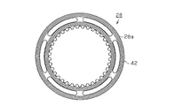
一方、本実施形態のパイロットクラッチ23は、上記メインクラッチ14と同様の多板式摩擦クラッチ機構であり、1枚のインナクラッチプレート28と該インナクラッチプレート28を挟むように配置された2枚のアウタクラッチプレート29とにより構成されている(図3参照)。そして、インナクラッチプレート28は第1カム25の外周に、また各アウタクラッチプレート29はフロントハウジング12の内周にスプライン嵌合されることにより、それぞれ軸方向に沿って移動可能に支持されている。
On the other hand, the
ここで、本実施形態では、フロントハウジング12の開口部12bには、円環状に形成されたリヤハウジング30が螺着されており、その中央孔31には、フロントハウジング12の筒内に収容されたインナシャフト13の一端が挿通されている。そして、リヤハウジング30の外周とフロントハウジング12の内周との間、及びリヤハウジング30の内周とインナシャフト13の外周との間には、シール部材32a,32bが介在されている。
Here, in this embodiment, an annular
即ち、本実施形態の駆動力伝達装置6では、メインクラッチ14及びパイロットクラッチ23を収容するフロントハウジング12の筒内、詳しくはフロントハウジング12の内周、インナシャフト13の外周、及びリヤハウジング30に囲まれた空間は、液密に構成されており、同空間には潤滑油が充填されている。そして、本実施形態のメインクラッチ14及びパイロットクラッチ23は、その各インナクラッチプレート18,28と各アウタクラッチプレート19,29とが潤滑油が介在された状態で摩擦係合する湿式の摩擦クラッチ機構として構成されている。
That is, in the driving
また、リヤハウジング30は、その軸方向外側に開口する断面U字状の磁石収容溝33を有しており、電磁石21は、同電磁石21の周囲を包囲するヨーク34とともに、リヤハウジング30、詳しくはその中央孔31から軸方向外側に延びる筒状部30aに設けられた軸受35に軸支されることにより、同磁石収容溝33内に配置されている。そして、アーマチャ22は、電磁石21(及びリヤハウジング30)との間にパイロットクラッチ23を挟む位置において、フロントハウジング12の内周にスプライン嵌合されることにより、軸方向に沿って移動可能に支持されている。
The
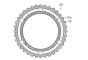
電磁石21へ通電すると、電磁石21の周囲に磁界が発生する。この磁界の磁束は、ヨーク34,リヤハウジング30,インナクラッチプレート28及びアウタクラッチプレート29の外周部,アーマチャ22,インナクラッチプレート28及びアウタクラッチプレート29の内周部を通過する磁路を流れる。即ち、磁路はインナクラッチプレート28とアウタクラッチプレート29の摺動面を通過して形成されている。なお、リヤハウジング30のパイロットクラッチ23に面した部分には環状の非磁性体が圧入及び溶接され、磁束の短絡が防止されている。また、図4及び図5に示すように、インナクラッチプレート28及びアウタクラッチプレート29の外周部と内周部の間には円弧状の切欠きが複数設けられ、この切欠きによっても磁束の短絡が防がれている。
When the electromagnet 21 is energized, a magnetic field is generated around the electromagnet 21. The magnetic flux of the magnetic field flows through a magnetic path passing through the outer peripheral portions of the
このように構成された駆動力伝達装置6において、電磁石21へ通電すると、発生する電磁力によってアーマチャ22が吸引され同電磁石21側に移動することにより、パイロットクラッチ23が摩擦係合する。これによりカム機構24を構成する第1カム25と第2カム26とが相対回転する。そして、この第1カム25と第2カム26との間の相対回転に基づいて、第2カム26が第1カム25から離間するようにメインクラッチ14側に移動し、同第2カム26によりインナクラッチプレート18が押圧されることにより、メインクラッチ14が摩擦係合する。
In the driving
つまり、電磁石21に対する通電量を制御しその磁力を変化させることで、パイロットクラッチ23の摩擦係合力が変化し、これにより、第1カム25と第2カム26との間の相対回転速度、即ちメインクラッチ14(インナクラッチプレート18)を押圧する力が変化する。従って、電磁石21に対する通電量を制御することにより、メインクラッチ14の摩擦係合力、即ちプロペラシャフト5からピニオンシャフト7へと伝達される駆動力を制御することができるようになっている。
That is, by controlling the energization amount to the electromagnet 21 and changing the magnetic force thereof, the frictional engagement force of the
次に、上記各摩擦クラッチ機構(インナクラッチプレート及びパイロットクラッチ)を構成する駆動力伝達部材(クラッチプレート)の特徴的構成について説明する。
図3〜図5に示すように、本実施形態では、インナクラッチプレート28及びアウタクラッチプレート29は、ともに磁性金属(鉄系金属)により円環状に形成されており、アウタクラッチプレート29側の摺動面29aには、DLC被膜(ダイヤモンド状炭素被膜)41が形成されている。尚、本実施形態では、DLC被膜41として、シリコンを含有するDLC−Si被膜が形成されている。DLC被膜中のSi濃度は8wt%〜40wt%が適切であり、膜の硬度は1000Hv以上であることが望ましい。そして、インナクラッチプレート28側の摺動面28aには、複数の微細溝42が、同インナクラッチプレート28の軸心、即ちアウタクラッチプレート29との間の相対回転の軸心を中心として円周方向に形成されている。即ち、本実施形態では、アウタクラッチプレート29(19)により第1駆動力伝達部材が構成され、インナクラッチプレート28(18)により第2駆動力伝達部材が構成されている。
Next, a characteristic configuration of the driving force transmission member (clutch plate) constituting each of the friction clutch mechanisms (inner clutch plate and pilot clutch) will be described.
As shown in FIGS. 3 to 5, in this embodiment, the inner
詳述すると、図6に示すように、本実施形態では、各微細溝42は、金型を用いたプレス加工により、使用初期におけるその溝深さ、即ち溝底までの深さD0が溝深さが15μm以下となるように形成されている。そして、各微細溝42は、その摺動面28aの表面における溝幅W1の平均値が15〜45μmであり、且つ摺動面28aの表面からの深さD1(1.5μm)における溝幅W2の平均値もまた15〜45μmである。また、駆動力伝達特性の変化を抑えるためには、15〜45μmである。また、駆動力伝達特性の変化を抑えるためには、少なくとも60%以上であることが望ましい。
More specifically, as shown in FIG. 6, in this embodiment, each
尚、図6は使用初期におけるインナクラッチプレート28の摺動面を表したものであり、本図において摺動面28aの表面は、プレス加工により微細溝42を形成した後にならしを行い、摺動面の不整な凹凸を除去した後の摺動面の表面である。また、深さD1は、その製品の寿命として想定される長期使用時における最大磨耗に対応するものである。さらになお、本実施形態では、アウタクラッチプレート29の摺動面29aには、パイロットクラッチ23の係合時にクラッチプレート間に存在する潤滑油を排出するための格子状の油溝43が形成されている。そして、インナクラッチプレート28の摺動面28aには、酸窒化膜44が形成されている。
FIG. 6 shows the sliding surface of the inner
図7は、インナクラッチプレート28の摺動面の摺接領域の割合に対するμ−v勾配を示したものである。この図に示すように、摺接領域の割合が90%以下であればμ−v勾配が1以上、即ち正勾配となる。一般にμ−v勾配が正勾配であれば回転速度の変化時におけるジャダー振動(不整振動)が抑制されることが知られているので、摺接領域の割合は全使用期間を通して90%以下とすべきである。
FIG. 7 shows the μ-v gradient with respect to the ratio of the sliding contact area of the sliding surface of the inner
図8は、インナクラッチプレート28の摺動面の摺接領域の割合に対する伝達トルクの最大値(トルク容量)を示したものである。この図に示すように、摺接領域の割合が55%以上であれば伝達トルクの最大値の変化率は小さくなる。これは、摺動面の単位面積あたりの摺接領域がある程度確保されていれば、摺接領域が小さくなることに逆比例して面圧が高くなることにより、摩擦力が維持されるためと考えられる。従って、摺接領域の割合が55%以上であれば、インナクラッチプレート28の摺動面が磨耗して摺接領域の割合が変化したとしても、伝達トルクの最大値は大きくは変化しない。即ち、駆動力伝達装置6の使用初期の時点おけるインナクラッチプレート28の摺動面の摺接領域の割合が55%以上であれば、その後の使用により摺接領域の割合が増加しても、伝達トルクの最大値の経時変化は小さく抑えられる。また、使用初期における摺接領域の割合が70%以上であれば、より一層伝達トルクの最大値の経時変化は小さく抑えられる。
FIG. 8 shows the maximum value (torque capacity) of the transmission torque with respect to the ratio of the sliding contact area of the sliding surface of the inner
インナクラッチプレート28の摺動面の摺接領域の割合は、図9に模式的に示すように、摺動面全体の面積に対する摺接領域の面積の比として求められる。なお、図9は、説明のため、溝の深さ方向に対する幅方向の寸法を約20分の1に縮尺したものである。また、本明細書において「使用初期」とは、具体的には本発明に係る駆動力伝達装置が市場の流通過程に最初におかれた時点での状態をいう。
The ratio of the sliding contact area of the sliding surface of the inner
(作用・効果)
次に、上記のように構成された本実施形態の駆動力伝達装置の作用・効果について説明する。図10(a)は、DLC被膜を形成したアウタクラッチプレートと、使用初期における摺動面の摺接領域の割合を50%,微細溝の溝深さを20μmとしたインナクラッチプレートとを備えた駆動力伝達装置の駆動力伝達特性の経時変化を示すグラフである。一方、図10(b)は、同じくDLC被膜を形成したアウタクラッチプレートと、摺動面の摺接領域の割合を55%,微細溝の溝深さを15μmとしたインナクラッチプレートを備えた本実施形態の駆動力伝達装置の駆動力伝達特性の変化を示すグラフである。両グラフの縦軸は、使用初期における伝達トルクを基準として使用時間に対する伝達トルクの変化の割合(トルクアップ率)を示したものである。また、グラフ中の0.55〜2.90Aの各電流値は、電磁石21に通電した電流の値である。これらグラフから明らかなように、摺動面の摺接領域の割合を大きくし、さらには微細溝の溝深さを浅くすることで、伝達トルクの経時変化が抑えられている。
(Action / Effect)
Next, operations and effects of the driving force transmission device of the present embodiment configured as described above will be described. FIG. 10A includes an outer clutch plate on which a DLC film is formed, and an inner clutch plate in which the ratio of the sliding contact area of the sliding surface in the initial stage of use is 50% and the groove depth of the fine groove is 20 μm. It is a graph which shows a time-dependent change of the driving force transmission characteristic of a driving force transmission device. On the other hand, FIG. 10B shows a book provided with an outer clutch plate similarly formed with a DLC film and an inner clutch plate having a sliding contact area ratio of 55% and a groove depth of 15 μm. It is a graph which shows the change of the driving force transmission characteristic of the driving force transmission device of an embodiment. The vertical axis of both graphs shows the rate of change in the transmission torque with respect to the usage time (torque-up rate) based on the transmission torque in the initial stage of use. In addition, each current value of 0.55 to 2.90 A in the graph is the value of the current that has passed through the electromagnet 21. As is apparent from these graphs, the change in the transmission torque with time is suppressed by increasing the ratio of the sliding contact area of the sliding surface and further decreasing the depth of the fine groove.
なお、本実施形態は以下のように変更してもよい。
・本実施形態では、アウタクラッチプレート29側の摺動面29aにDLC被膜(ダイヤモンド状炭素被膜)41を形成し、インナクラッチプレート28側の摺動面28aに、複数の微細溝42を形成した。しかし、これに限らず、アウタクラッチプレート29側の摺動面29aに複数の微細溝を形成し、インナクラッチプレート28側の摺動面28aにDLC被膜を形成する構成としてもよい。
In addition, you may change this embodiment as follows.
In this embodiment, a DLC film (diamond-like carbon film) 41 is formed on the sliding
・本実施形態では、DLC被膜41として、シリコンを含有するDLC−Si被膜を形成することとしたが、シリコンを含有しないDLC被膜としてもよい。
・本実施形態では、各微細溝42は、インナクラッチプレート28の軸心、即ちアウタクラッチプレート29との間の相対回転の軸心を中心として円周方向に形成されることとしたが、必ずしも円周方向ではなく、例えば格子状等でもよい。
In the present embodiment, the DLC-Si film containing silicon is formed as the
In the present embodiment, each
・本実施形態では、各微細溝42は、微細溝42は、金型を用いたプレス加工により形成されるとしたが、これ以外の方法により形成される構成としてもよい。
・本実施形態では、本発明を四輪駆動車の補助駆動輪(後輪)へ駆動力を伝達する駆動力伝達装置のパイロットクラッチに適用した場合について説明したが、これに限らず、車両のマニュアルトランスミッション用シンクロナイザーリングやCVT等に適用してもよい。また、車両の駆動力を伝達する装置に限られるものでもない。
In the present embodiment, each
-In this embodiment, although the case where this invention was applied to the pilot clutch of the drive force transmission device which transmits a drive force to the auxiliary drive wheel (rear wheel) of a four-wheel drive vehicle was demonstrated, not only this but vehicle You may apply to the synchronizer ring for manual transmission, CVT, etc. Further, the present invention is not limited to a device that transmits the driving force of the vehicle.
6…駆動力伝達装置、14…メインクラッチ、18,28…インナクラッチプレート、19,29…アウタクラッチプレート、23…パイロットクラッチ、28a…摺動面、41…DLC被膜、42…微細溝、D0,D1…深さ、W1,W2…溝幅。 6 ... Driving force transmission device, 14 ... Main clutch, 18, 28 ... Inner clutch plate, 19, 29 ... Outer clutch plate, 23 ... Pilot clutch, 28a ... Sliding surface, 41 ... DLC coating, 42 ... Fine groove, D0 , D1 ... depth, W1, W2 ... groove width.
Claims (4)
第1駆動力伝達部材の摺動面にはダイヤモンド状炭素被膜が形成されるとともに、第2駆動力伝達部材の摺動面には微細溝が形成され、
使用初期における前記微細溝は、溝深さが15μm以下に形成されるとともに、前記第2駆動力伝達部材の摺動面の表面における溝幅の平均値が15〜45μmであり、且つ前記摺動面の表面からの深さ1.5μmにおける溝幅の平均値もまた15〜45μmであり、使用初期における前記第2駆動力伝達部材の摺動面の摺接領域の割合が55〜90%であり、
前記第2駆動力伝達部材の摺動面が使用初期の状態から1.5μm磨耗した状態における摺接領域の割合が55〜90%であること、を特徴とする駆動力伝達装置。 A driving force transmission device that transmits a driving force by frictional engagement with lubricating oil interposed between first and second driving force transmission members arranged coaxially so as to be relatively rotatable,
A diamond-like carbon film is formed on the sliding surface of the first driving force transmission member, and a fine groove is formed on the sliding surface of the second driving force transmission member.
The fine groove in the initial stage of use is formed with a groove depth of 15 μm or less, an average value of the groove width on the surface of the sliding surface of the second driving force transmission member is 15 to 45 μm, and the sliding The average value of the groove width at a depth of 1.5 μm from the surface of the surface is also 15 to 45 μm, and the ratio of the sliding contact area of the sliding surface of the second driving force transmission member in the initial use is 55 to 90%. Oh it is,
The driving force transmission device according to claim 1, wherein a ratio of a sliding contact area in a state where the sliding surface of the second driving force transmission member is worn by 1.5 μm from an initial use state is 55 to 90% .
前記微細溝は、プレス加工により形成されてなること、を特徴とする駆動力伝達装置。 The driving force transmission device according to claim 1,
The driving force transmitting device , wherein the fine groove is formed by press working .
前記微細溝は、前記相対回転の回転軸心を中心とする円周方向に形成されてなること、
を特徴とする駆動力伝達装置。 In the driving force transmission device according to claim 1 or 2,
The fine groove is formed in a circumferential direction around the rotation axis of the relative rotation ;
A driving force transmission device characterized by the above.
前記第1及び第2駆動力伝達部材は、これらの摺動面を通過して形成される磁路による電磁力によって押圧されること、
を特徴とする駆動力伝達装置。 In the driving force transmission device according to any one of claims 1 to 3,
The first and second driving force transmission members are pressed by electromagnetic force generated by a magnetic path formed by passing through these sliding surfaces ;
A driving force transmission device characterized by the above.
Priority Applications (4)
| Application Number | Priority Date | Filing Date | Title |
|---|---|---|---|
| JP2005248894A JP4880947B2 (en) | 2005-08-30 | 2005-08-30 | Driving force transmission device |
| EP06119784A EP1783389B1 (en) | 2005-08-30 | 2006-08-30 | Drive force transmission device |
| DE602006002948T DE602006002948D1 (en) | 2005-08-30 | 2006-08-30 | Power drive device |
| US11/512,214 US7677375B2 (en) | 2005-08-30 | 2006-08-30 | Drive force transmission device |
Applications Claiming Priority (1)
| Application Number | Priority Date | Filing Date | Title |
|---|---|---|---|
| JP2005248894A JP4880947B2 (en) | 2005-08-30 | 2005-08-30 | Driving force transmission device |
Publications (2)
| Publication Number | Publication Date |
|---|---|
| JP2007064289A JP2007064289A (en) | 2007-03-15 |
| JP4880947B2 true JP4880947B2 (en) | 2012-02-22 |
Family
ID=37831422
Family Applications (1)
| Application Number | Title | Priority Date | Filing Date |
|---|---|---|---|
| JP2005248894A Active JP4880947B2 (en) | 2005-08-30 | 2005-08-30 | Driving force transmission device |
Country Status (4)
| Country | Link |
|---|---|
| US (1) | US7677375B2 (en) |
| EP (1) | EP1783389B1 (en) |
| JP (1) | JP4880947B2 (en) |
| DE (1) | DE602006002948D1 (en) |
Families Citing this family (13)
| Publication number | Priority date | Publication date | Assignee | Title |
|---|---|---|---|---|
| JP5240497B2 (en) * | 2005-10-07 | 2013-07-17 | 株式会社ジェイテクト | Spline shaft |
| US9574155B2 (en) | 2008-07-02 | 2017-02-21 | Nanotech Lubricants, LLC | Lubricant with nanodiamonds and method of making the same |
| AT510943A1 (en) * | 2011-01-13 | 2012-07-15 | Miba Frictec Gmbh | FRICTION MATERIAL |
| WO2013156244A2 (en) * | 2012-04-16 | 2013-10-24 | Schaeffler Technologies AG & Co. KG | Mating surface of a friction pairing |
| JP6236930B2 (en) * | 2012-07-27 | 2017-11-29 | 株式会社ジェイテクト | Friction clutch plate, friction clutch and driving force transmission device |
| JP2014098436A (en) * | 2012-11-14 | 2014-05-29 | Jtekt Corp | Clutch plate, clutch device, and driving force transmitting device |
| EP3048321B1 (en) * | 2013-09-18 | 2018-02-07 | Nissan Motor Co., Ltd | Friction engagement element, dry clutch, and method for manufacturing friction engagement element |
| JP2016023754A (en) | 2014-07-23 | 2016-02-08 | Nskワーナー株式会社 | Friction plate and wet multiple disk clutch including friction plate |
| JP6519310B2 (en) * | 2015-05-13 | 2019-05-29 | 株式会社ジェイテクト | Electromagnetic friction engagement device |
| RU179891U1 (en) * | 2017-10-09 | 2018-05-28 | Публичное акционерное общество "Завод фрикционных и термостойких материалов" | Friction disc |
| JP6685070B1 (en) * | 2019-10-25 | 2020-04-22 | 株式会社エフ・シー・シー | Joined parts, multi-disc clutch device including the joined parts, and method for manufacturing joined parts |
| US10989258B1 (en) | 2019-10-25 | 2021-04-27 | The Hilliard Corporation | Flexible armature plate for an electro-magnetic overrunning clutch |
| US11708867B2 (en) * | 2021-01-26 | 2023-07-25 | Borgwarner Inc. | Power transfer component with clutch having components with geometry for increased strength and/or reduced mass |
Family Cites Families (18)
| Publication number | Priority date | Publication date | Assignee | Title |
|---|---|---|---|---|
| US2733798A (en) * | 1956-02-07 | Composite wxt clutch | ||
| US3048250A (en) * | 1959-10-26 | 1962-08-07 | Lambert & Brake Corp | Friction disc for brakes, clutches and the like |
| US3972400A (en) | 1974-08-09 | 1976-08-03 | Caterpillar Tractor Co. | Friction disc for clutches and the like |
| US5004089A (en) * | 1988-11-22 | 1991-04-02 | Hitachi Chemical Company, Ltd. | Clutch driven plates and method of producing the same |
| US5029686A (en) | 1990-07-20 | 1991-07-09 | Borg-Warner Automotive, Inc. | Clutch separator plates |
| JPH07127658A (en) * | 1993-11-01 | 1995-05-16 | Nissan Motor Co Ltd | Wet type friction member |
| JPH07190113A (en) * | 1993-12-28 | 1995-07-28 | Mitsubishi Materials Corp | Facing mechanism |
| JPH0874905A (en) * | 1994-08-31 | 1996-03-19 | Honda Motor Co Ltd | Wet frictional material |
| JPH10331889A (en) * | 1997-05-29 | 1998-12-15 | Dainatsukusu:Kk | Wet type friction plate provided with pores in its surface |
| US6158561A (en) * | 1998-04-01 | 2000-12-12 | Toyoda Koki Kabushiki Kaisha | Clutch plate |
| JP2002213485A (en) * | 2001-01-18 | 2002-07-31 | Toyoda Mach Works Ltd | Drive force transmission device |
| JP2003130084A (en) * | 2001-10-23 | 2003-05-08 | Tochigi Fuji Ind Co Ltd | Wet friction clutch plate |
| EP1571365B1 (en) * | 2001-12-25 | 2008-01-02 | Jtekt Corporation | Clutch plate, friction clutch, and coupling device |
| JP3961879B2 (en) * | 2002-05-24 | 2007-08-22 | 株式会社豊田中央研究所 | Friction clutch and driving force transmission device |
| US20040159519A1 (en) * | 2003-02-14 | 2004-08-19 | Gorman Michael J. | Clutch reaction plates with cooling flow path |
| JP2005036863A (en) * | 2003-07-18 | 2005-02-10 | Toyoda Mach Works Ltd | Friction clutch and driving force transmission device |
| DE10342271B4 (en) * | 2003-09-12 | 2014-07-10 | Zf Friedrichshafen Ag | Friction lining plate |
| US7448483B2 (en) * | 2004-06-25 | 2008-11-11 | General Motors Corporation | Clutch cooling grooves for uniform plate temperature in friction launch |
-
2005
- 2005-08-30 JP JP2005248894A patent/JP4880947B2/en active Active
-
2006
- 2006-08-30 EP EP06119784A patent/EP1783389B1/en not_active Ceased
- 2006-08-30 DE DE602006002948T patent/DE602006002948D1/en active Active
- 2006-08-30 US US11/512,214 patent/US7677375B2/en active Active
Also Published As
| Publication number | Publication date |
|---|---|
| JP2007064289A (en) | 2007-03-15 |
| EP1783389A2 (en) | 2007-05-09 |
| EP1783389B1 (en) | 2008-10-01 |
| US7677375B2 (en) | 2010-03-16 |
| US20070108009A1 (en) | 2007-05-17 |
| EP1783389A3 (en) | 2007-05-16 |
| DE602006002948D1 (en) | 2008-11-13 |
Similar Documents
| Publication | Publication Date | Title |
|---|---|---|
| JP4880947B2 (en) | Driving force transmission device | |
| JP3853686B2 (en) | Electromagnetic brake | |
| WO2013027834A1 (en) | Clutch plate | |
| US9080614B2 (en) | Clutch plate, clutch unit and driving force transmission system | |
| US9133891B2 (en) | Friction clutch plate, friction clutch and driving force transmission apparatus | |
| KR20160057409A (en) | A coupling for an awd vehicle | |
| JP5909992B2 (en) | Driving force transmission device and design method thereof | |
| JP2009109020A (en) | Assembly method of drive force transmitting equipment using electromagnetic clutch | |
| JP2010096239A (en) | Driving force transmitting device | |
| JP2011122679A (en) | Electromagnetic clutch | |
| JP2002213485A (en) | Drive force transmission device | |
| JP5504900B2 (en) | Cam mechanism and electromagnetic clutch | |
| JP4186990B2 (en) | Driving force transmission device | |
| JP3009382B2 (en) | Clutch plate and driving force transmission device using the same | |
| JP2005036863A (en) | Friction clutch and driving force transmission device | |
| JP4626201B2 (en) | Electromagnetic clutch device | |
| JP6428846B2 (en) | Clutch plate, clutch device, and driving force transmission device | |
| JP4622229B2 (en) | Driving force transmission device | |
| JP3834419B2 (en) | Clutch plate and electromagnetic friction clutch using the same | |
| JP6432228B2 (en) | Electromagnetic clutch device | |
| JP2011122680A (en) | Electromagnetic clutch | |
| JP4051868B2 (en) | Driving force transmission device and torque transmission adjustment method for driving force transmission device | |
| JP2009138798A (en) | Electromagnetic clutch and driving force transmission device | |
| JP2015121279A (en) | Driving force transmission device | |
| JP2019124232A (en) | Drive force transmission device |
Legal Events
| Date | Code | Title | Description |
|---|---|---|---|
| A621 | Written request for application examination |
Free format text: JAPANESE INTERMEDIATE CODE: A621 Effective date: 20080625 |
|
| A977 | Report on retrieval |
Free format text: JAPANESE INTERMEDIATE CODE: A971007 Effective date: 20101108 |
|
| A131 | Notification of reasons for refusal |
Free format text: JAPANESE INTERMEDIATE CODE: A131 Effective date: 20110405 |
|
| A521 | Request for written amendment filed |
Free format text: JAPANESE INTERMEDIATE CODE: A523 Effective date: 20110530 |
|
| TRDD | Decision of grant or rejection written | ||
| A01 | Written decision to grant a patent or to grant a registration (utility model) |
Free format text: JAPANESE INTERMEDIATE CODE: A01 Effective date: 20111129 |
|
| A01 | Written decision to grant a patent or to grant a registration (utility model) |
Free format text: JAPANESE INTERMEDIATE CODE: A01 |
|
| A61 | First payment of annual fees (during grant procedure) |
Free format text: JAPANESE INTERMEDIATE CODE: A61 Effective date: 20111202 |
|
| R150 | Certificate of patent or registration of utility model |
Ref document number: 4880947 Country of ref document: JP Free format text: JAPANESE INTERMEDIATE CODE: R150 Free format text: JAPANESE INTERMEDIATE CODE: R150 |
|
| FPAY | Renewal fee payment (event date is renewal date of database) |
Free format text: PAYMENT UNTIL: 20141209 Year of fee payment: 3 |
|
| FPAY | Renewal fee payment (event date is renewal date of database) |
Free format text: PAYMENT UNTIL: 20141209 Year of fee payment: 3 |
|
| S531 | Written request for registration of change of domicile |
Free format text: JAPANESE INTERMEDIATE CODE: R313532 |
|
| FPAY | Renewal fee payment (event date is renewal date of database) |
Free format text: PAYMENT UNTIL: 20141209 Year of fee payment: 3 |
|
| R350 | Written notification of registration of transfer |
Free format text: JAPANESE INTERMEDIATE CODE: R350 |