JP4880418B2 - Manual-use article cover element set in particular for the arrangement of at least one substance, and a manual-use article comprising such a cover element - Google Patents
Manual-use article cover element set in particular for the arrangement of at least one substance, and a manual-use article comprising such a cover element Download PDFInfo
- Publication number
- JP4880418B2 JP4880418B2 JP2006282595A JP2006282595A JP4880418B2 JP 4880418 B2 JP4880418 B2 JP 4880418B2 JP 2006282595 A JP2006282595 A JP 2006282595A JP 2006282595 A JP2006282595 A JP 2006282595A JP 4880418 B2 JP4880418 B2 JP 4880418B2
- Authority
- JP
- Japan
- Prior art keywords
- abutment surface
- cover element
- article
- case
- element according
- Prior art date
- Legal status (The legal status is an assumption and is not a legal conclusion. Google has not performed a legal analysis and makes no representation as to the accuracy of the status listed.)
- Active
Links
- 239000000126 substance Substances 0.000 title claims description 8
- 238000010168 coupling process Methods 0.000 claims description 8
- 238000005859 coupling reaction Methods 0.000 claims description 8
- 210000003811 finger Anatomy 0.000 claims description 8
- 210000003813 thumb Anatomy 0.000 claims description 8
- 230000002093 peripheral effect Effects 0.000 claims description 7
- 230000000694 effects Effects 0.000 claims 1
- 230000008878 coupling Effects 0.000 description 7
- 239000000853 adhesive Substances 0.000 description 2
- 230000001070 adhesive effect Effects 0.000 description 2
- 238000005273 aeration Methods 0.000 description 2
- 239000002989 correction material Substances 0.000 description 2
- 239000002537 cosmetic Substances 0.000 description 2
- 239000012530 fluid Substances 0.000 description 2
- 210000004247 hand Anatomy 0.000 description 2
- 238000000926 separation method Methods 0.000 description 2
- 230000006978 adaptation Effects 0.000 description 1
- 230000007423 decrease Effects 0.000 description 1
- 238000010586 diagram Methods 0.000 description 1
- 238000000034 method Methods 0.000 description 1
- 230000035807 sensation Effects 0.000 description 1
- 238000011282 treatment Methods 0.000 description 1
- 230000001960 triggered effect Effects 0.000 description 1
Images


Classifications
-
- B—PERFORMING OPERATIONS; TRANSPORTING
- B43—WRITING OR DRAWING IMPLEMENTS; BUREAU ACCESSORIES
- B43K—IMPLEMENTS FOR WRITING OR DRAWING
- B43K23/00—Holders or connectors for writing implements; Means for protecting the writing-points
-
- B—PERFORMING OPERATIONS; TRANSPORTING
- B43—WRITING OR DRAWING IMPLEMENTS; BUREAU ACCESSORIES
- B43K—IMPLEMENTS FOR WRITING OR DRAWING
- B43K23/00—Holders or connectors for writing implements; Means for protecting the writing-points
- B43K23/08—Protecting means, e.g. caps
-
- B—PERFORMING OPERATIONS; TRANSPORTING
- B43—WRITING OR DRAWING IMPLEMENTS; BUREAU ACCESSORIES
- B43K—IMPLEMENTS FOR WRITING OR DRAWING
- B43K23/00—Holders or connectors for writing implements; Means for protecting the writing-points
- B43K23/08—Protecting means, e.g. caps
- B43K23/12—Protecting means, e.g. caps for pens
- B43K23/122—Protecting means, e.g. caps for pens with means for preventing choking
- B43K23/124—Protecting means, e.g. caps for pens with means for preventing choking comprising an air passage
-
- B—PERFORMING OPERATIONS; TRANSPORTING
- B43—WRITING OR DRAWING IMPLEMENTS; BUREAU ACCESSORIES
- B43L—ARTICLES FOR WRITING OR DRAWING UPON; WRITING OR DRAWING AIDS; ACCESSORIES FOR WRITING OR DRAWING
- B43L19/00—Erasers, rubbers, or erasing devices; Holders therefor
- B43L19/0018—Erasers, rubbers, or erasing devices; Holders therefor with fluids
-
- B—PERFORMING OPERATIONS; TRANSPORTING
- B43—WRITING OR DRAWING IMPLEMENTS; BUREAU ACCESSORIES
- B43M—BUREAU ACCESSORIES NOT OTHERWISE PROVIDED FOR
- B43M11/00—Hand or desk devices of the office or personal type for applying liquid, other than ink, by contact to surfaces, e.g. for applying adhesive
- B43M11/06—Hand-held devices
-
- A—HUMAN NECESSITIES
- A45—HAND OR TRAVELLING ARTICLES
- A45D—HAIRDRESSING OR SHAVING EQUIPMENT; EQUIPMENT FOR COSMETICS OR COSMETIC TREATMENTS, e.g. FOR MANICURING OR PEDICURING
- A45D40/00—Casings or accessories specially adapted for storing or handling solid or pasty toiletry or cosmetic substances, e.g. shaving soaps or lipsticks
- A45D40/20—Pencil-like cosmetics; Simple holders for handling stick-shaped cosmetics or shaving soap while in use
Description
本発明は、特に少なくとも1つの流体物質の配置のために設定される、手動使用の物品用カバー要素に関する。 The present invention relates to a cover element for a manually used article, especially set for the placement of at least one fluid substance.
本発明は、さらに、上述のカバー要素が設けられる流体物質を配置するための、ペンあるいは類似装置などの手動使用の物品に関する。 The invention further relates to an article for manual use, such as a pen or similar device, for placing a fluid substance provided with a cover element as described above.
本発明は、特に傷つきやすい、及び/又は繊細な部分のために外側カバーを必要とするあらゆる商品分野に、かつ、あらゆる手動使用の物品に用いられるように構成されている。たとえば、事務用品に関して、本発明の物体は、ペン、フェルトペン、マーカー、修正液、接着剤及び/又は類似商品に適用することが可能であり、それらが使用中でないとき、前述の物品の先端を保護する。本発明は、さらに、リップスティック、マスカラ、アイライナー、チューブ又はスティック状の類似製品などの化粧品の分野で、広範囲にわたって使用されることが可能である。本発明の用途は、これが多数の異なるセクターに広がるので、いずれかの特定の商品分野に限定されることができないほど広範囲であることは明らかである。 The present invention is configured to be used in any commodity field that requires an outer cover for particularly vulnerable and / or delicate parts, and for any manually used article. For example, with respect to office supplies, the objects of the present invention can be applied to pens, felt pens, markers, correction fluids, adhesives and / or similar items, and when they are not in use, the tips of the aforementioned articles Protect. The invention can also be used extensively in the field of cosmetics such as lipsticks, mascaras, eyeliners, tubes or similar products in the form of sticks. It is clear that the application of the present invention is so broad that it cannot be limited to any particular product area, as it extends to many different sectors.
上述の物品などの特に傷つきやすい、及び/又は繊細な部分のカバーは、ねじ留め及び/又は嵌め込みによる相互係合を介して一般に適用されるふた、キャップ、プラグ及び/又は類似のカバー要素を通常基にすることは知られている。特に、カバー要素が、それらの使用部分において、それぞれの物品の方へ元に戻されるとき、閉鎖要素は、所望の係合が得られるまで、手動作用を介して本体又は対応する物品にねじ留めされるか、又は、本体又は対応する物品の方へ押し進められるかである。 Particularly vulnerable and / or delicate cover, such as the above-mentioned articles, usually has lids, caps, plugs and / or similar cover elements that are commonly applied via screwing and / or inlaying engagement. It is known to base. In particular, when the cover elements are replaced in their use part towards the respective article, the closure element is screwed to the body or the corresponding article via manual action until the desired engagement is obtained. Or pushed towards the body or the corresponding article.
対応する物品の方への閉鎖要素の適用が行われるのと同じ方法で、使用部分の解放が、前述の物品が係合した物品から分離されるまで、カバー要素をねじって外すことによって、又は、これを移動して離すことによって、行われる。カバー要素の適用及び解放は、両方とも、2本以上の指を使用して手動で行われ、そのために、対応する手の完全使用が必要とされる。 In the same way that the closure element is applied towards the corresponding article, by unscrewing the cover element until the release of the use part is separated from the engaged article, or This is done by moving and releasing it. The application and release of the cover element is both done manually using two or more fingers, which requires full use of the corresponding hand.
物品にねじ係合手段が設けられる場合、前記適用及び解放操作のために、これが、カバー要素に影響を与える手の作用に対して反対方向にこれの長手方向軸まわりに物品に回転を与える際、最初の手を助ける必要があるので、さらに、もう1本の手の使用が必要とされる。これとは反対に、嵌め込みによる係合を行う手段の存在では、物品の本体は、前述の物品の分離を行う手に対して反対方向に引かれることになる。 If the article is provided with screw engaging means, for the application and release operation, this will give the article rotation about its longitudinal axis in the opposite direction to the hand action affecting the cover element. Since it is necessary to help the first hand, the use of another hand is also required. On the contrary, in the presence of means for engaging by fitting, the body of the article is pulled in the opposite direction with respect to the hand performing the separation of the article.
上記の理由に基づき、本出願人は、手動使用の物品用の周知のカバー要素が、それらが通常適用される商品の傷つきやすい、及び/又は繊細な部分を十分に保護するのに対して、それらは、いくつかの欠点を有し、異なる観点のもとに改良されることが可能であることが分かった。 Based on the above reasons, Applicants have found that well-known cover elements for manually used articles provide sufficient protection for sensitive and / or delicate parts of the goods to which they are normally applied, It has been found that they have several drawbacks and can be improved under different aspects.
特に、本出願人は、前記カバー要素が、それぞれの物品からの前述の物品の離脱又は解放と、この操作を行う際の快適さと容易さとに対して、改善されることが可能であることに気付いた。 In particular, the Applicant believes that the cover element can be improved with respect to the detachment or release of the aforementioned article from the respective article and the comfort and ease of performing this operation. Noticed.
実際に、本出願人は、前述の物品のカバー要素を離脱及び/又は適用させるために、手動使用の本物品が、強制的に両手の使用を必要とすることが分かった。この要件を満たすことは通常きわめて簡単であるのに対して、使用者の少なくとも1本の手が、何らかの理由で、前記操作を行うことができないとき、特に難しくなることがある。換言すれば、1本の手での使用が不可能であることによって、明らかに容易である操作を行うことを難しくさせる。 In fact, the Applicant has found that the manual use of the article forces the use of both hands in order to allow the cover element of the article to be removed and / or applied. Satisfying this requirement is usually quite simple, but can be particularly difficult when at least one hand of the user is unable to perform the operation for some reason. In other words, it is difficult to perform an operation that is obviously easy because it cannot be used with one hand.
本出願人は、前記カバー要素の適用及び/又は離脱のための本テクニックがさらに容易に行われ、簡素化されることが可能であることに、最終的に気付いた。
本発明の目的は、特に少なくとも1つの物質の配置のために設定される、手動使用の物品用カバー要素を提供することによって、当技術分野において周知である欠点を回避することであり、それは、簡単で、容易な適用と取り外しとであり、加えて、使用者だけによる1本の手の使用を必要とする。 The object of the present invention is to avoid the disadvantages well known in the art by providing a cover element for a manually used article, especially set for the placement of at least one substance, Simple and easy to apply and remove, plus requires the use of one hand by the user alone.
本発明によれば、この目的は、説明され、添付の特許請求の範囲に主張される特色による、特に少なくとも1つの物質の配置のために設定される、物品用カバー要素によって、又は、前記カバー要素が設けられる手動使用の物品によって達成される。 According to the invention, this object is achieved by the cover element for an article, characterized by the features described and claimed in the appended claims, in particular for the arrangement of at least one substance, or said cover This is achieved by a manually used article provided with an element.
本発明は、ここでは、限定的ではないが、本発明による、特に少なくとも1つの物質の配置のために設定される物品用カバー要素、及び/又は前記カバー要素が設けられる手動使用の物品の好ましい一実施形態を示す、添付の図面を参照して説明されている。 The invention is here, but not exclusively, preferred according to the invention for an article cover element, in particular configured for the arrangement of at least one substance, and / or a manually used article provided with said cover element Reference will now be made to the accompanying drawings, which illustrate one embodiment.
図面を参照すると、本発明による、特に少なくとも1つの物質の配置のために設定される、手動使用の物品用カバー要素が、全体として参照符号1で確認される。
Referring to the drawings, a cover element for manually used articles, in particular set up for the arrangement of at least one substance, according to the present invention, is identified generally by the
特に、カバー要素1は、事務用品、化粧品、医療処置かつ身体処置用などの物品の分野などの異なる商品分野で見出されることが可能な、手動使用の物品2のあらゆるタイプ(図1と、図3から図5)に使用されるように構成されている。換言すれば、カバー要素1は、少なくとも部分的にカバーされ、保護される物品2の存在がある場合、あらゆる商品セクターにおいて用途を見出すことが可能である。
In particular, the
特に図1及び図3から図5を参照すると、一例としてここに示され、したがって、本発明を限定する存在のためではない物品2は、ペン、フェルトペン、修正液、接着剤などの円筒形事務用品2であることが好ましい。
With particular reference to FIGS. 1 and 3-5, the
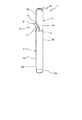
さらに、図1及び図3から図5を参照すると、物品2は、ほぼ細長い形状の本体2aを備え、それの1つの端部2bにおいて、少なくとも1つの使用部分2c(図3に部分的に見られる)を有し、その部分は、使用されていない状態で、前記カバー要素1に少なくとも部分的にカバーされるように構成される。第1の端部2bから対向する側に、物品2は、ほぼ先細になり、かつ円形の構成の第2の端部2dを有し、それの断面が次第に減少し、そのために、これは、締りばめによる係合で、物品自体の使用の間上述のカバー要素1を受容することが可能な部分2eで終端する。
1 and 3-5, the
さらに添付の図面を参照すると、カバー要素1は、ほぼ細長い、先細になる形状の少なくとも1つの中空のケース3を備える。詳細には、中空のケース3は、物品が使用されないとき物品2の使用部分2cを受容するために適切なアクセス開口4が設けられる第1の端部3aと、必要な場合、適切なエアレーションポート3c(図1、図2及び図5)が設けられる第1の端部3aに対向する、第2のほぼ円形の端部3bとを有する。
Still referring to the accompanying drawings, the
カバー要素1は、さらに、カバー要素1をそれぞれの物品2と確実に係合するために、中空のケース3と連結される結合手段(周知であるので図示せず)を備える。結合手段は、カバー要素1の起こり得る引き離しを妨げるような方法で、物品2の第1の端部2bに配置されるそれぞれの結合要素(図示せず)と協働する、少なくとも1つのスナップフックシステムを有することが好ましい。
The
カバー要素1は、中空のケース3と連結される当接手段5を備え、使用者による少なくとも1つの手動作用の結果として伴う、これがそれぞれの物品2に係合する結合状態(図1、図4及び図5)と、これが分離される解放状態(図2及び図3)との間に、カバー要素をシフトさせることが利点である。
The
添付図面に示されるように、当接手段5は、中空のケース3から外側に、中空のケース3の長手方向延長部の横に突出する、少なくとも1つの隆起部6の存在を意図している。特に、隆起部6は、カバー要素1が結合状態(図1、図4及び図5)に配置されるとき物品2に面する第1の当接表面7を有する。第1の当接表面7は、ケース3に対して対向する側に存在し、カバー要素1の長手方向延長部に対して傾斜延長部を結果として伴うことが好ましい。より詳細には、第1の当接表面7は、中空のケース3から離れて径方向に移動し、中空のケースの第1の端部3aから、第2の端部3bの方へ向ってスタートする。
As shown in the accompanying drawings, the abutment means 5 is intended for the presence of at least one
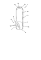
再度添付の図面を参照すると、第1の当接表面7は、アーチ形延長部を有する。前記第1の当接表面7はほぼ陥凹形であり、陥凹中央領域と、隆起周辺領域とをそれぞれ画定することが好ましい。 Referring again to the accompanying drawings, the first abutment surface 7 has an arcuate extension. Preferably, the first abutment surface 7 is substantially recessed and defines a recessed central region and a raised peripheral region.
図2に示されるように、第1の当接表面7は、ほぼ円形の周辺エッジ7aを有し、その外形は、少なくとも部分的に楕円形構成を有する。第1の当接表面7の形状は、1本の手8の1本の指の指先8a、好ましくは、親指8bの形状にマッチすることが利点であり、そのために、エルゴノミック係合で対応する指を受容するように構成される。
As shown in FIG. 2, the first abutment surface 7 has a substantially circular
隆起部6は、さらに、第1の当接表面7と中空のケース3との間に、中空のケースの、かつ第1の当接表面7の横に延在する、第2の当接表面9を有する。詳細には、第2の当接表面9は、ケース3の外側表面を接合するために、第1の当接表面7の周辺エッジ7aからスタートして延在する。換言すれば、第2の当接表面9は、第1の当接表面7まわりに周辺に延在し、部分的にこれを囲む。
The raised
第2の当接表面9も、アーチ形延長部を有し、陥凹部であることが好ましい。第2の当接表面9は、中断なく中空のケース3と接続され、そのために、第2の当接表面9と中空のケース3の外側表面との間のラインは、触感によって感じられることがないことが利点である。
The
図5に示される本発明の別の実施形態によれば、カバー要素1は、カバー要素1と、ポケット、ループなどのガーメントの少なくとも1つのほぼ平坦な部分との係合のために中空のケース3から延出する、少なくとも1つのフックテールピース10を備える。
According to another embodiment of the invention shown in FIG. 5, the
図5に示されるように、フックテールピース10は、隆起部6に対して対向する側に中空のケース3から延出し、中空のケース3の第2の端部3bから中空のケース3の第1の端部3aの方へ向って突出し、アクセス開口4に近接する位置で終端する。
As shown in FIG. 5, the
構造に関して主として上記に説明される本発明の操作は、以下のとおりである。 The operation of the present invention, mainly described above with respect to structure, is as follows.
図3に示されるように、上述のカバー要素1が設けられる物品2が使用されるとき、これは、親指8b以外のすべての指が物品2の本体2aを囲み、これのまわりに近接されるように1本の手8で把持されることが可能である。この位置において、親指8bは、当然のことながら、カバー要素1のケース3の隆起部6にあることが利点である。結果として、親指8bは、第1の当接表面7に置き、これの特定の形状は、使用者の指とカバー要素1との間の相互適合の最良の関係を確実とする。
As shown in FIG. 3, when an
物品2から離れるようにカバー要素1を移動しようとする(方向矢印「A」によって図3に確認される)適切なスラスト作用を結果として伴い、前記カバー要素1は、物品の使用部分2cから離れて移動する物品2の長手方向軸に沿って平行移動する。
With the appropriate thrust action (identified in FIG. 3 by directional arrow “A”) trying to move the
明らかに、第1の当接表面7の形状により、十分な強度のスラスト作用が、親指8bによって行われることを可能にし、カバー要素1の結合手段によって発生する抵抗を解消し、結合状態から解放状態へカバー要素自体1をシフトさせる。
Obviously, the shape of the first abutment surface 7 allows a sufficiently strong thrust action to be performed by the
カバー要素1の分離は、前記物品2の本体2aを囲み、これを保持する使用者の指によって容易に行われる。
The
これとは反対に、図4を参照すると、解放状態から結合状態へのカバー要素1のシフトは、解放方向(図4の方向矢印「B」)に対して対向する方向にカバー要素1に加わる別のスラスト作用によって生じる。この状態のもとに、使用者の手8は、物品2のまわりに近接状態に維持されるが、親指8bは、周辺エッジ7a全体にわたってあり、第2の当接表面9に支承し、第2の当接表面9を要素2の方へ向って押し進める。カバー要素1は、結合手段がカバー要素1と要素2との間に確実な係合を生じるまで、要素2に近接して移動する。
On the contrary, referring to FIG. 4, the shift of the
図5に示される実施形態を参照すると、カバー要素の操作は、変更されていない。しかしながら、フックテールピース10の存在のために、使用者のガーメントへの、物品2と結合されるカバー要素1の適応が、可能とされる。
Referring to the embodiment shown in FIG. 5, the operation of the cover element is unchanged. However, due to the presence of the
本発明は、周知の技術において見出される問題点を解決し、意図された目的を達する。 The present invention solves problems found in the known art and achieves the intended purpose.
まず、上記に説明されるカバー要素の当接手段の特定の構造のために、これをそれぞれの物品から解放するための操作は容易に行われる。 First, because of the specific structure of the abutment means of the cover element described above, the operation for releasing it from the respective article is easily performed.
加えて、前記当接手段は、さらに、カバー要素と対応する物品との間の結合操作を簡素化するのに使用されることが可能である。 In addition, the abutment means can further be used to simplify the coupling operation between the cover element and the corresponding article.
いっそう詳細には、カバー要素を解放する、及び/又は結合するための操作は、簡単で迅速な動きによって、1本の手だけの使用を介して行われることが可能であることが利点である。換言すれば、設計されるような閉鎖要素により、もう1本の手の力を借りずに、それぞれの物品の使用部分からの分離を可能にし、そのために、両手を物理的に利用することができないあらゆる使用者の使用が容易になる。 More particularly, it is an advantage that the operation for releasing and / or joining the cover elements can be performed through the use of only one hand with a simple and quick movement. . In other words, the closure element as designed allows the separation of each article from the use part without the help of another hand, so that both hands can be physically utilized. It becomes easy for any user who cannot.
1 カバー要素
2 物品
2a 本体
2b、3a 第1の端部
2c 使用状態
2d、3b 第2の端部
2e 部分
3 中空のケース
3c エアレーションポート
4 アクセス開口
5 当接手段
6 隆起部
7 第1の当接表面
7a 周辺エッジ
8 1本の手
8a 指先
8b 親指
9 第2の当接表面
10 フックテールピース
DESCRIPTION OF
Claims (16)
−中に挿入される手動使用の物品(2)の少なくとも1つのそれぞれの使用部分(2c)を受容するように、少なくとも1つのアクセス開口(4)が設けられる、少なくとも1つの第1の端部(3a)を有する中空のケース(3)と、
−前記カバー要素(1)と前記それぞれの物品(2)との係合を確実にするために、前記ケース(3)と連結される結合手段と、
を備え、
前記カバー要素(1)は、少なくとも1つの手動作用の効果によって、それぞれの物品(2)に係合する結合状態と、前記物品(2)から分離される解放状態との間の、前記カバー要素(1)のシフトを引き起こす前記ケース(3)に連結される当接手段(5)をさらに備え、
前記当接手段(5)は、前記ケース(3)から外側に、前記カバー要素(1)の長手方向延長部の横に突出する、少なくとも1つの隆起部(6)を備え、前記隆起部(6)は、前記ケース(3)に対して対向する側に存在する第1の当接表面(7)を有し、
前記第1の当接表面(7)は、前記カバー要素(1)の長手方向延長部に対して傾斜延長部を結果として伴い、中空ケースの前記第1の端部(3a)から第2の端部(3b)の方へ向かってスタートし、前記中空ケース(3)から離れて径方向に移動する、ことを特徴とする、カバー要素。 A cover element (1) for a manually used article (2), specifically configured for the arrangement of at least one substance, said cover element (1) comprising:
At least one first end provided with at least one access opening (4) to receive at least one respective use part (2c) of the manually used article (2) inserted therein; A hollow case (3) having (3a) ;
-Coupling means connected to the case (3) in order to ensure the engagement between the cover element (1) and the respective article (2);
With
The cover element (1) has a cover element between a coupled state engaged with a respective article (2) and a released state separated from the article (2) by the effect of at least one manual action. A further contact means (5) connected to the case (3) causing the shift of (1) ;
Said abutment means (5) comprises at least one ridge (6) projecting laterally of the longitudinal extension of said cover element (1) on the outside from said case (3), said ridge ( 6) has a first abutment surface (7) present on the side facing the case (3);
The first abutment surface (7) results in an inclined extension with respect to the longitudinal extension of the cover element (1), and from the first end (3a) of the hollow case to the second Covering element, characterized in that it starts towards the end (3b) and moves radially away from the hollow case (3) .
Applications Claiming Priority (2)
| Application Number | Priority Date | Filing Date | Title |
|---|---|---|---|
| EP05425905.6 | 2005-12-22 | ||
| EP05425905A EP1808309B1 (en) | 2005-12-22 | 2005-12-22 | Covering element for writing instrumens |
Publications (2)
| Publication Number | Publication Date |
|---|---|
| JP2007168903A JP2007168903A (en) | 2007-07-05 |
| JP4880418B2 true JP4880418B2 (en) | 2012-02-22 |
Family
ID=36218464
Family Applications (1)
| Application Number | Title | Priority Date | Filing Date |
|---|---|---|---|
| JP2006282595A Active JP4880418B2 (en) | 2005-12-22 | 2006-10-17 | Manual-use article cover element set in particular for the arrangement of at least one substance, and a manual-use article comprising such a cover element |
Country Status (12)
| Country | Link |
|---|---|
| US (1) | US7785028B2 (en) |
| EP (1) | EP1808309B1 (en) |
| JP (1) | JP4880418B2 (en) |
| KR (1) | KR101237046B1 (en) |
| CN (1) | CN1986242B (en) |
| AR (1) | AR058713A1 (en) |
| AT (1) | ATE385909T1 (en) |
| CA (1) | CA2553015C (en) |
| DE (1) | DE602005004816T2 (en) |
| ES (1) | ES2299991T3 (en) |
| HK (1) | HK1104017A1 (en) |
| MX (1) | MXPA06015247A (en) |
Families Citing this family (2)
| Publication number | Priority date | Publication date | Assignee | Title |
|---|---|---|---|---|
| DE202011109167U1 (en) | 2011-12-09 | 2013-03-11 | Volkmar Rommel | writing implement |
| US10231529B2 (en) * | 2013-02-04 | 2019-03-19 | Raymond G. Anderson | Non-roll stick product containers |
Family Cites Families (14)
| Publication number | Priority date | Publication date | Assignee | Title |
|---|---|---|---|---|
| US1201082A (en) * | 1916-01-13 | 1916-10-10 | William O Nussbaumer | Closure for milk-cans. |
| JPH0318496U (en) * | 1989-06-30 | 1991-02-22 | ||
| US6036385A (en) * | 1991-02-07 | 2000-03-14 | Bistrack; Carl | Adaptable pressure writing instrument holder |
| DE9115124U1 (en) * | 1991-12-05 | 1992-04-02 | Pelikan Ag, 3000 Hannover, De | |
| US5352053A (en) * | 1993-07-08 | 1994-10-04 | Frederick Reitze | Writing instrument and cap |
| ES2138050T3 (en) * | 1994-09-26 | 2000-01-01 | Frederick Reitze | IMPROVED WRITING INSTRUMENT. |
| JPH08112994A (en) * | 1994-09-30 | 1996-05-07 | Reitze Frederic | Writing utensil |
| KR970003361Y1 (en) * | 1994-10-25 | 1997-04-16 | 전정근 | Writing instrument |
| WO1998019871A1 (en) * | 1996-11-06 | 1998-05-14 | Fulvio Franchi | Automatic pen |
| US6168024B1 (en) * | 1999-10-21 | 2001-01-02 | Revlon Consumer Products Corporation | Cosmetic pencil and case |
| USD425124S (en) * | 1999-11-04 | 2000-05-16 | We-Chin Chen | Pen cap |
| JP2003072284A (en) * | 2001-08-31 | 2003-03-12 | Pilot Corp | Cap-type ball-point pen |
| US6695513B1 (en) * | 2002-08-29 | 2004-02-24 | Linda M. Malek | Hair product application package and method of use |
| USD504464S1 (en) * | 2003-11-25 | 2005-04-26 | Kevin Martzloff | Glitter marker |
-
2005
- 2005-12-22 DE DE602005004816T patent/DE602005004816T2/en active Active
- 2005-12-22 AT AT05425905T patent/ATE385909T1/en not_active IP Right Cessation
- 2005-12-22 EP EP05425905A patent/EP1808309B1/en active Active
- 2005-12-22 ES ES05425905T patent/ES2299991T3/en active Active
-
2006
- 2006-07-21 CA CA2553015A patent/CA2553015C/en active Active
- 2006-08-04 US US11/498,807 patent/US7785028B2/en active Active
- 2006-08-07 KR KR1020060074422A patent/KR101237046B1/en active IP Right Grant
- 2006-08-31 CN CN2006101288562A patent/CN1986242B/en active Active
- 2006-10-17 JP JP2006282595A patent/JP4880418B2/en active Active
- 2006-12-20 AR ARP060105687A patent/AR058713A1/en active IP Right Grant
- 2006-12-20 MX MXPA06015247A patent/MXPA06015247A/en active IP Right Grant
-
2007
- 2007-08-14 HK HK07108803.3A patent/HK1104017A1/en not_active IP Right Cessation
Also Published As
| Publication number | Publication date |
|---|---|
| ATE385909T1 (en) | 2008-03-15 |
| ES2299991T3 (en) | 2008-06-01 |
| CN1986242A (en) | 2007-06-27 |
| CA2553015C (en) | 2013-04-02 |
| KR20070066838A (en) | 2007-06-27 |
| EP1808309B1 (en) | 2008-02-13 |
| CN1986242B (en) | 2010-10-06 |
| MXPA06015247A (en) | 2008-10-23 |
| CA2553015A1 (en) | 2007-06-22 |
| AR058713A1 (en) | 2008-02-20 |
| JP2007168903A (en) | 2007-07-05 |
| DE602005004816T2 (en) | 2009-04-23 |
| HK1104017A1 (en) | 2008-01-04 |
| DE602005004816D1 (en) | 2008-03-27 |
| EP1808309A1 (en) | 2007-07-18 |
| US20070147951A1 (en) | 2007-06-28 |
| US7785028B2 (en) | 2010-08-31 |
| KR101237046B1 (en) | 2013-02-25 |
Similar Documents
| Publication | Publication Date | Title |
|---|---|---|
| USD572362S1 (en) | Tampon applicator with finger grip | |
| US9883760B2 (en) | Disposable food grasping device | |
| USD891589S1 (en) | Garden hose with couplers and colors | |
| WO2007089306A3 (en) | Tampon applicator | |
| HUP0002276A2 (en) | Syringe for bleeding | |
| JP2000071674A (en) | Writing instrument | |
| USD583508S1 (en) | Golf glove | |
| JP4880418B2 (en) | Manual-use article cover element set in particular for the arrangement of at least one substance, and a manual-use article comprising such a cover element | |
| JP6296705B2 (en) | Connecting tool for pincer used by hand | |
| USD528737S1 (en) | Glove | |
| KR101096315B1 (en) | A finger cap | |
| USD595028S1 (en) | Glove | |
| RU2234409C2 (en) | Tool handle | |
| US20040025277A1 (en) | Smoother with a friction sleeve on handle | |
| JP3198660U (en) | Glove slip-off prevention device | |
| USD455429S1 (en) | Ambidextrous computer input device | |
| USD910429S1 (en) | Band clip | |
| KR200300764Y1 (en) | pen cap | |
| KR200332383Y1 (en) | A combined fork and nippers | |
| JPH0852960A (en) | Fingerstall | |
| US20180116309A1 (en) | Makeup Application System | |
| KR101815872B1 (en) | Rubber glove hanger | |
| KR200479558Y1 (en) | Portable Sharp-type Swab | |
| KR200444646Y1 (en) | A sanitaty implement for food | |
| JP3040620U (en) | A writing instrument lid with an umbrella-shaped protrusion that can be sandwiched between your fingers |
Legal Events
| Date | Code | Title | Description |
|---|---|---|---|
| A621 | Written request for application examination |
Free format text: JAPANESE INTERMEDIATE CODE: A621 Effective date: 20081119 |
|
| A977 | Report on retrieval |
Free format text: JAPANESE INTERMEDIATE CODE: A971007 Effective date: 20110520 |
|
| A131 | Notification of reasons for refusal |
Free format text: JAPANESE INTERMEDIATE CODE: A131 Effective date: 20110524 |
|
| A521 | Request for written amendment filed |
Free format text: JAPANESE INTERMEDIATE CODE: A523 Effective date: 20110818 |
|
| TRDD | Decision of grant or rejection written | ||
| A01 | Written decision to grant a patent or to grant a registration (utility model) |
Free format text: JAPANESE INTERMEDIATE CODE: A01 Effective date: 20111101 |
|
| A01 | Written decision to grant a patent or to grant a registration (utility model) |
Free format text: JAPANESE INTERMEDIATE CODE: A01 |
|
| A61 | First payment of annual fees (during grant procedure) |
Free format text: JAPANESE INTERMEDIATE CODE: A61 Effective date: 20111201 |
|
| R150 | Certificate of patent or registration of utility model |
Ref document number: 4880418 Country of ref document: JP Free format text: JAPANESE INTERMEDIATE CODE: R150 Free format text: JAPANESE INTERMEDIATE CODE: R150 |
|
| FPAY | Renewal fee payment (event date is renewal date of database) |
Free format text: PAYMENT UNTIL: 20141209 Year of fee payment: 3 |
|
| R250 | Receipt of annual fees |
Free format text: JAPANESE INTERMEDIATE CODE: R250 |
|
| S111 | Request for change of ownership or part of ownership |
Free format text: JAPANESE INTERMEDIATE CODE: R313111 |
|
| R350 | Written notification of registration of transfer |
Free format text: JAPANESE INTERMEDIATE CODE: R350 |
|
| R250 | Receipt of annual fees |
Free format text: JAPANESE INTERMEDIATE CODE: R250 |
|
| R250 | Receipt of annual fees |
Free format text: JAPANESE INTERMEDIATE CODE: R250 |
|
| R250 | Receipt of annual fees |
Free format text: JAPANESE INTERMEDIATE CODE: R250 |
|
| R250 | Receipt of annual fees |
Free format text: JAPANESE INTERMEDIATE CODE: R250 |
|
| R250 | Receipt of annual fees |
Free format text: JAPANESE INTERMEDIATE CODE: R250 |
|
| R250 | Receipt of annual fees |
Free format text: JAPANESE INTERMEDIATE CODE: R250 |
|
| R250 | Receipt of annual fees |
Free format text: JAPANESE INTERMEDIATE CODE: R250 |
|
| R250 | Receipt of annual fees |
Free format text: JAPANESE INTERMEDIATE CODE: R250 |
|
| R250 | Receipt of annual fees |
Free format text: JAPANESE INTERMEDIATE CODE: R250 |