JP4878226B2 - Drive device - Google Patents
Drive device Download PDFInfo
- Publication number
- JP4878226B2 JP4878226B2 JP2006175210A JP2006175210A JP4878226B2 JP 4878226 B2 JP4878226 B2 JP 4878226B2 JP 2006175210 A JP2006175210 A JP 2006175210A JP 2006175210 A JP2006175210 A JP 2006175210A JP 4878226 B2 JP4878226 B2 JP 4878226B2
- Authority
- JP
- Japan
- Prior art keywords
- magnet
- rotor yoke
- yoke
- magnetic pole
- stator
- Prior art date
- Legal status (The legal status is an assumption and is not a legal conclusion. Google has not performed a legal analysis and makes no representation as to the accuracy of the status listed.)
- Expired - Fee Related
Links
Images


Classifications
-
- H—ELECTRICITY
- H02—GENERATION; CONVERSION OR DISTRIBUTION OF ELECTRIC POWER
- H02K—DYNAMO-ELECTRIC MACHINES
- H02K37/00—Motors with rotor rotating step by step and without interrupter or commutator driven by the rotor, e.g. stepping motors
- H02K37/10—Motors with rotor rotating step by step and without interrupter or commutator driven by the rotor, e.g. stepping motors of permanent magnet type
- H02K37/20—Motors with rotor rotating step by step and without interrupter or commutator driven by the rotor, e.g. stepping motors of permanent magnet type with rotating flux distributors, the armatures and magnets both being stationary
Landscapes
- Engineering & Computer Science (AREA)
- Power Engineering (AREA)
- Iron Core Of Rotating Electric Machines (AREA)
Description
本発明は、ステッピングモータの軸方向の寸法の短縮を図る場合に適用される駆動装置に関する。 The present invention relates to a drive device applied when reducing the axial dimension of a stepping motor.
従来、各種機構の駆動源としてステッピングモータが広範に活用されている。ステッピングモータの第1の従来例として、回転軸を中心とする直径を小さくし且つ出力を高めたステッピングモータが提案されている(例えば、特許文献1参照)。 Conventionally, stepping motors have been widely used as drive sources for various mechanisms. As a first conventional example of a stepping motor, there has been proposed a stepping motor in which the diameter around the rotation axis is reduced and the output is increased (see, for example, Patent Document 1).
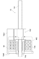
図21は、第1の従来例に係るステッピングモータの構成部品を示す分解斜視図である。図22は、組立完成状態におけるステッピングモータの軸方向の構造を示す断面図である。 FIG. 21 is an exploded perspective view showing components of the stepping motor according to the first conventional example. FIG. 22 is a cross-sectional view showing the axial structure of the stepping motor in the assembled state.
図21及び図22において、ステッピングモータは、マグネット101、第1のコイル102、第2のコイル103、第1のステータ104、第2のステータ105、出力軸106、連結リング107を備えている。マグネット101は、円筒形状に構成され、円周方向に4分割されると共に異なる極性に交互に着磁されている。
21 and 22, the stepping motor includes a
上記構成を有するステッピングモータは、第1のコイル102へ通電することにより、第1の外側磁極104A、第1の内側磁極104C、マグネット101と一周する第1の磁気回路を構成する。また、第2のコイル103へ通電することにより、第2の外側磁極105A、第2の内側磁極105C、マグネット101と一周する第2の磁気回路を構成する。第1の磁気回路、第2の磁気回路へ流れる磁束を切り替えることにより、マグネット101に働く力を変化させ、マグネット101及び出力軸106からなるロータを回転させるものである。
The stepping motor having the above-described configuration forms a first magnetic circuit that goes around the first outer
第1の従来例のステッピングモータでは、第1及び第2の磁気回路における空隙が、外側磁極とマグネット101の間及びマグネット101と内側磁極の間のみにすることができるので、磁気回路の抵抗を小さくすることができる。そして、外側磁極と内側磁極の間に位置するマグネット101に磁束が効率的に作用する。その結果、少ない電流で多くの磁束を発生させることができ、ステッピングモータの出力が向上する。
In the stepping motor of the first conventional example, the air gap in the first and second magnetic circuits can be made only between the outer magnetic pole and the
また、ステッピングモータの第2の従来例として、第1の従来例と同じ磁気回路の構成をとったまま、中空円筒形状としたステッピングモータが提案されている(例えば、特許文献2参照)。この種のステッピングモータをカメラに搭載する場合、カメラのレンズ鏡筒内で光軸と平行になるようにモータを配置し、モータの内径側に絞り羽根、シャッタ、レンズ等を配置する。これにより、内径側にスペースがない中実構造のモータを利用した場合よりもスペース効率の良い構成をとることができ、カメラのレンズ鏡筒の直径を小さくすることができる。 As a second conventional example of a stepping motor, there has been proposed a stepping motor having a hollow cylindrical shape with the same magnetic circuit configuration as that of the first conventional example (see, for example, Patent Document 2). When this type of stepping motor is mounted on a camera, the motor is arranged in parallel with the optical axis in the lens barrel of the camera, and a diaphragm blade, a shutter, a lens, and the like are arranged on the inner diameter side of the motor. As a result, a space-efficient configuration can be achieved as compared with a case where a solid structure motor having no space on the inner diameter side is used, and the diameter of the lens barrel of the camera can be reduced.
上記第1及び第2の従来例のステッピングモータでは、径の大きな永久磁石をロータとして用いている。そのため、ロータの慣性モーメントが大きくなり、ステッピングモータの高速回転時の応答特性が悪化するという欠点があった。 In the stepping motors of the first and second conventional examples, a permanent magnet having a large diameter is used as the rotor. For this reason, there has been a drawback that the moment of inertia of the rotor is increased and the response characteristics at the time of high-speed rotation of the stepping motor are deteriorated.
そこで、上記高速回転時の応答特性を改善するために、コイルと永久磁石を固定子として用い、ヨークを回転子として用いる構造のステッピングモータが提案されている(例えば特許文献3)。 Therefore, in order to improve the response characteristics at the time of high speed rotation, a stepping motor having a structure using a coil and a permanent magnet as a stator and a yoke as a rotor has been proposed (for example, Patent Document 3).
図23は、第3の従来例に係るステッピングモータの構成部品を示す分解斜視図である。図24は、組立完成状態におけるステッピングモータの軸方向の構造を示す断面図である。 FIG. 23 is an exploded perspective view showing components of a stepping motor according to a third conventional example. FIG. 24 is a cross-sectional view showing the axial structure of the stepping motor in the assembled state.
図23及び図24において、ステッピングモータは、第1の外ヨーク207、第1の内ヨーク208、第1の天板ヨーク209、第2の外ヨーク210、第2の内ヨーク211、第2の天板ヨーク212を備えている。ステッピングモータは、更に、第1のコイル213、第2のコイル214、第1のマグネット215、第2のマグネット216、第1のロータヨーク217、第2のロータヨーク218を備えている。
23 and 24, the stepping motor includes a first
第1コイル213及び第2コイル214に通電することで発生した磁束は、それぞれ、第1及び第2の外ヨーク、第1及び第2の天板ヨーク、第1及び第2の内ヨーク、第1及び第2のロータヨーク、第1及び第2のマグネットと一周する第1及び第2の磁気回路を構成する。第1の磁気回路、第2の磁気回路へ流れる磁束を切り替えることにより、マグネットとロータヨークの間に働く力を変化させ、第1及び第2のロータヨークからなるロータを回転させるものである。
Magnetic fluxes generated by energizing the
第3の従来例のステッピングモータでは、第1の従来例のステッピングモータと同様の磁路構成をとりながらも、マグネットよりも慣性モーメントの小さいロータヨークを回転子として配置することができる。これにより、高速回転時のモータの応答特性を改善することができる。
しかしながら、上記第1乃至第3の従来例のステッピングモータは、第1の磁気回路と第2の磁気回路を軸方向に並べて配置した構成となっている。この種のステッピングモータの軸方向の寸法を短くするためには、第1の磁気回路と第2の磁気回路の間隔を短くしていくことが必要である。 However, the stepping motors of the first to third conventional examples have a configuration in which the first magnetic circuit and the second magnetic circuit are arranged side by side in the axial direction. In order to shorten the axial dimension of this type of stepping motor, it is necessary to shorten the distance between the first magnetic circuit and the second magnetic circuit.
しかし、第1の磁気回路と第2の磁気回路の間隔を狭くすると、磁気回路同士が干渉を起こしてしまい、ステッピングモータを所定の回転位置に止めることができなくなる、コギングトルクの増加につながる、などの問題が発生する。これを避けるため、第1及び第2の磁気回路の間にはある程度の間隔を設ける必要がある。このため、ステッピングモータの軸方向の寸法の短縮(短軸化)が難しいという問題があった。 However, if the interval between the first magnetic circuit and the second magnetic circuit is reduced, the magnetic circuits interfere with each other, and the stepping motor cannot be stopped at a predetermined rotational position, leading to an increase in cogging torque. Problems occur. In order to avoid this, it is necessary to provide a certain distance between the first and second magnetic circuits. For this reason, there has been a problem that it is difficult to reduce the axial dimension of the stepping motor (short axis).
本発明の目的は、軸方向の寸法の短縮を可能とした駆動装置を提供することにある。 An object of the present invention is to provide a drive device that can reduce the axial dimension.
上述の目的を達成するために、本発明の駆動装置は、シャフト部と前記シャフト部から径方向に突出する複数の磁極部が形成されたロータヨークと、前記ロータヨークの前記磁極部に対向するように配置されるものであって、円弧形状を有し、内周面に周方向に沿って交互に異なる磁極が着磁された第1のマグネットと、前記第1のマグネットの外周面に接するように配置されるものであって、前記ロータヨークのシャフト部の一方端を回転可能に軸支する第1のステータヨークと、前記第1のステータヨークを介して、前記ロータヨークの磁極部を励磁する第1のコイルと、前記ロータヨークの前記磁極部に対向するように配置されるものであって、円弧形状を有し、内周面に周方向に沿って交互に異なる磁極が着磁された第2のマグネットと、前記第2のマグネットの外周面に接するように配置されるものであって、前記ロータヨークのシャフト部の他方端を回転可能に軸支する第2のステータヨークと、前記第2のステータヨークを介して、前記ロータヨークの磁極部を励磁する第2のコイルとを備え、
前記第1のマグネットと前記第2のマグネットは前記ロータヨークの径方向にて互いに向かい合うように配置され、前記第1のマグネットと前記第2のマグネットとの間に前記ロータヨークが配置され、前記第1のマグネットの磁極に対して前記第2のマグネットの磁極が所定の位相差を持つように、前記第1のマグネットと前記第2のマグネットとは配置されることを特徴とする。
In order to achieve the above-described object, the drive device of the present invention is configured so that a shaft portion, a rotor yoke formed with a plurality of magnetic pole portions projecting radially from the shaft portion, and the magnetic pole portion of the rotor yoke are opposed to each other. be those that are arranged, has an arc shape, a first magnet magnetic poles different alternately in the inner circumferential surface along the circumferential direction are magnetized so as to be in contact with the outer peripheral surface of the first magnet A first stator yoke that rotatably supports one end of the shaft portion of the rotor yoke, and a first magnetic portion that excites the magnetic pole portion of the rotor yoke via the first stator yoke. and coils, there is disposed so as to face the magnetic pole portion of the rotor yoke has a circular arc shape, a second different magnetic poles alternately in the inner circumferential surface along the circumferential direction are magnetized Magnet A second stator yoke that is disposed in contact with the outer peripheral surface of the second magnet and rotatably supports the other end of the shaft portion of the rotor yoke; and the second stator yoke And a second coil for exciting the magnetic pole part of the rotor yoke,
Wherein the first magnet second magnet is disposed so as to face each other in the radial direction of the rotor yoke, the rotor yoke is disposed between the first magnet and said second magnet, said first of to have a phase difference magnetic pole of a predetermined said second magnet relative to the magnetic poles of the magnet, characterized in that is disposed between said first magnet and said second magnet.
本発明によれば、ロータヨークの径方向にて互いに向かい合うように配置される第1のマグネットと第2のマグネットとの間に上記ロータヨークを配置し、且つ第1のマグネットの磁極に対して第2のマグネットの磁極が所定の位相差を持つように、第1のマグネットと第2のマグネットを配置する。これにより、従来例のように第1及び第2のマグネットを軸方向に並べて配置する構成に比べて、駆動装置の軸方向の寸法を短縮した短軸化を実現することが可能となる。 According to the present invention, the rotor yoke is disposed between the first magnet and the second magnet that are disposed so as to face each other in the radial direction of the rotor yoke, and the second with respect to the magnetic pole of the first magnet. The first magnet and the second magnet are arranged so that the magnetic poles of the magnets have a predetermined phase difference. As a result, it is possible to realize a shortened axis in which the dimension in the axial direction of the driving device is shortened as compared with the configuration in which the first and second magnets are arranged in the axial direction as in the conventional example.
以下、本発明の実施の形態を図面を参照して説明する。 Hereinafter, embodiments of the present invention will be described with reference to the drawings.
[第1の実施の形態]
図1は、本発明の第1の実施の形態に係る駆動装置としてのステッピングモータの構成部品を示す分解斜視図である。図2は、組立完成状態におけるステッピングモータの軸方向の構造を示す断面図である。図3は、図2の矢視A−A線に沿うステッピングモータの構造を示す断面図である。
[First Embodiment]
FIG. 1 is an exploded perspective view showing components of a stepping motor as a drive device according to the first embodiment of the present invention. FIG. 2 is a cross-sectional view showing the axial structure of the stepping motor in an assembled state. FIG. 3 is a cross-sectional view showing the structure of the stepping motor taken along the line AA in FIG.
図1乃至図3において、ステッピングモータは、第1のマグネット11a、第2のマグネット11b、第1のステータヨーク12a、第2のステータヨーク12bを備えている。ステッピングモータは、更に、第1のコイル13a、第2のコイル13b、第1の軸受14a、第2の軸受14b、ロータヨーク15を備えている。
1 to 3, the stepping motor includes a
第1のマグネット11aを説明するために、まず、円筒状の第1の仮想マグネットを考える。第1の仮想マグネットは、内周面がn分割(n:4以上の偶数、本実施の形態では8分割)されると共にS極とN極が交互に着磁されている。また、第1の仮想マグネットの外周面は、内周面に比べ弱い着磁分布を有するか、あるいは全く着磁されていないか、あるいは内周面と逆の極性に着磁されているかの何れかである。第1の仮想マグネットを軸方向に沿って分割し半円筒形状に形成したものが、第1のマグネット11aである。分割した後の第1のマグネット11aの着磁パターンについては後述する。第1のマグネット11aは、磁極部11a1〜11a4を備える。
In order to describe the
第2のマグネット11bは、第1のマグネット11aと同様に、内周面がS極とN極に交互に着磁された円筒状の第2の仮想マグネットを軸方向に沿って分割し半円筒形状に形成したものである。分割した後の第2のマグネット11bの着磁パターンについては後述する。第2のマグネット11bは、磁極部11b1〜11b4を備える。
Similarly to the
第1のステータヨーク12aは、軟磁性材料から形成されており、半円筒状の磁極部12a1と円盤状の天板部12a2から構成されている。第1のステータヨーク12aの磁極部12a1は、内径が第1のマグネット11aの外径と略等しい寸法に形成され、図3に示すように第1のマグネット11aの外周を覆うように配置される。
The
第1のステータヨーク12aの天板部12a2は、磁極部12a1と略同じ外径に形成され、天板部12a2の中心には、第1の軸受14aを支持するための穴部が配設されている。第1のステータヨーク12aは、ロータヨーク15と共に第1のマグネット11aの着磁パターンの形成箇所を挟み込む位置に配置される。
The top plate portion 12a2 of the
第2のステータヨーク12bは、第1のステータヨーク12aと同じ材料で同じ形状に構成されている。即ち、第2のステータヨーク12bは、軟磁性材料から形成されており、半円筒状の磁極部12b1と円盤状の天板部12b2から構成されている。第2のステータヨーク12bの磁極部12b1は、内径が第2のマグネット11bの外径と略等しい寸法に形成され、図3に示すように第2のマグネット11bの外周を覆うように配置される。
The
第2のステータヨーク12bの天板部12b2は、磁極部12b1と略同じ外径に形成され、天板部12b2の中心には、第2の軸受14bを支持するための穴部が配設されている。第2のステータヨーク12bは、ロータヨーク15と共に第2のマグネット11bの着磁パターンの形成箇所を挟み込む位置に配置される。
The top plate portion 12b2 of the
第1のコイル13aは、ロータヨーク15の中心軸を中心として第1のボビン13a1に導線を多数回巻回することで構成されている。第1のコイル13aの外径は、第1のマグネット11a(第2のマグネット11b)の外径と略同じ寸法に形成されている。
The
第2のコイル13bは、第1のコイル13aと同様の形状、巻数、抵抗値を有する。即ち、第2のコイル13bは、ロータヨーク15の中心軸を中心として第2のボビン13b1に導線を多数回巻回することで構成されている。第2のコイル13bの外径は、第1のマグネット11a(第2のマグネット11b)の外径と略同じ寸法に形成されている。
The
第1の軸受14aは、円筒形状に構成されており、内径部によりロータヨーク15を回転可能に支持する。第1の軸受14aを軟磁性材料で形成することにより、第1の軸受14aを磁路の一部として利用することが望ましい。第1の軸受14aとして好ましくは鉄粉を利用した含油焼結軸受を用いることにより、軸摩擦を減少させながら磁束を通すことが可能である。
The
第2の軸受14bは、第1の軸受14aと同じ形状を有する。即ち、第2の軸受14bは、円筒形状に構成されており、内径部によりロータヨーク15を回転可能に支持する。第2の軸受14bを軟磁性材料で形成することにより、第2の軸受14bを磁路の一部として利用することが望ましい。第2の軸受14bとして好ましくは鉄粉を利用した含油焼結軸受を用いることにより、軸摩擦を減少させながら磁束を通すことが可能である。
The
ロータヨーク15は、シャフト部151と磁極部152から構成されている。ロータヨーク15のシャフト部151は、第1の軸受14a及び第2の軸受14bに嵌合可能であり、軟磁性材料により形成することが好ましい。これにより、シャフト部151を磁気回路の一部として利用することができる。ロータヨーク15の磁極部152は、略直方体状の凸極がシャフト部151の中心軸から径方向に延出した形状であり、シャフト部151の外周方向に等間隔で軸方向に沿って設けられている。
The
ロータヨーク15の磁極部152の本数は、第1の仮想マグネットの着磁極数nの半分(本実施の形態では4本)に設定されている。また、ロータヨーク15の磁極部152の外径は、第1の仮想マグネットの内径よりもやや小さく形成されている。
The number of
以上、第1のステータヨーク12aに、第1のコイル13a、第1のマグネット11a、第1の軸受14aを固定することで、第1のステータユニットを構成する。また、第2のステータヨーク12bに、第2のコイル13b、第2のマグネット11b、第2の軸受14bを固定することで、第2のステータユニットを構成する。
As described above, the first stator unit is configured by fixing the
本実施の形態のステッピングモータの固定子は、上記の第1のステータユニット及び第2のステータユニット同士をカバーを用いるなど不図示の方法で同心状に固定することで構成している。 The stator of the stepping motor according to the present embodiment is configured by fixing the first stator unit and the second stator unit concentrically by a method (not shown) such as using a cover.
ここで、上記の第1のマグネット11aと第2のマグネット11bの着磁パターン及び位置関係を図3を用いて説明する。
Here, the magnetization pattern and positional relationship of the
上述したように、第1のマグネット11aは、内周面をn分割(本実施の形態では8分割)すると共にS極とN極を交互に着磁した第1の仮想マグネットを軸方向に沿って分割したものである。第1のマグネット11aは、ロータヨーク15の中心軸を中心とし、中心角が180°の扇形を底面とする柱に収まるように分割される。
As described above, the
また、上述したように、第2のマグネット11bは、第1のマグネット11aと同じ形状を有する。第2のマグネット11bは、第1のマグネット11aと同じピッチ且つ同じ強さで周方向に沿って着磁され、図3に示すように第1のマグネット11aと所定の位相差をつけて配置される。
Further, as described above, the second magnet 11b has the same shape as the
この場合、第1のマグネット11aと第2のマグネット11bの間には、図3に示すように、後述の第1の磁気回路と第2の磁気回路とが干渉しない程度の空隙を設けている。第1のマグネット11aと第2のマグネット11bにおける所定の位相差は、着磁ピッチPの1/4(電気角で90°、図3に(1/4)Pとして示す)を基本としている。但し、第1及び第2の磁気回路同士の干渉を低減させるために、上記電気角から数%ずらす場合もある。
In this case, a gap is provided between the
第1のマグネット11a及び第2のマグネット11bの内周の円弧部分の長さは、着磁ピッチの倍数となるとは限らず、第1のマグネット11a及び第2のマグネット11bのそれぞれの両端の磁極部は、他の磁極部に比べて小さくてもよい。本実施の形態では、第1のマグネット11aの磁極部11a4が、他の磁極部11a1〜11a3に比べて小さく構成されている。同様に、第2のマグネット11bの磁極部11b4が、他の磁極部11b1〜11b3に比べて小さく構成されている。
The lengths of the arc portions of the inner circumference of the
また、第1のステータヨーク12aの磁極部12a1は、第1のマグネット11aと略等しい中心角に設定されている。同様に、第2のステータヨーク12bの磁極部12b1は、第2のマグネット11bと略等しい中心角に設定されている。
Further, the magnetic pole portion 12a1 of the
また、本実施の形態のステッピングモータの回転子は、ロータヨーク15のシャフト部151を第1の軸受14a及び第2の軸受14bにより回転可能に支持することで構成している。このとき、ロータヨーク15の磁極部152は、第1のマグネット11a及び第2のマグネット11bの着磁面と対向する。
Further, the rotor of the stepping motor according to the present embodiment is configured by rotatably supporting the
本実施の形態のステッピングモータでは、第1のマグネット11a、第1のコイル13a、第1のステータヨーク12a、第1の軸受14a、ロータヨーク15により、第1の磁気回路を構成している。また、第2のマグネット11b、第2のコイル13b、第2のステータヨーク12b、第2の軸受14b、ロータヨーク15により、第2の磁気回路を構成している。
In the stepping motor of the present embodiment, the
次に、上記構成を有する本実施の形態のステッピングモータにおいて回転子を固定子に対して回転させる駆動原理について、図4乃至図9を参照しながら説明する。 Next, the driving principle of rotating the rotor with respect to the stator in the stepping motor of the present embodiment having the above-described configuration will be described with reference to FIGS.
図4は、ステッピングモータの磁気回路を示す図である。図5は、ステッピングモータのロータヨーク15における励磁領域を示す図である。
FIG. 4 is a diagram showing a magnetic circuit of the stepping motor. FIG. 5 is a diagram showing an excitation region in the
図4において、第1の磁気回路を構成する第1のマグネット11a、第1のコイル13a、第1のステータヨーク12a、第1の軸受14a、ロータヨーク15について、断面で示している。また、図5において、ロータヨーク15における第1のコイル13aが励磁する箇所である領域1と、第2のコイル13bが励磁する箇所である領域2を示している。
In FIG. 4, the
第1のコイル13aに逆通電を行うと、図4に示すように2つの磁路M1、M2が現れる。磁路M1は、第1のマグネット11a、第1のステータヨーク12aの磁極部12a1、天板部12a2、第1の軸受14a、ロータヨーク15のシャフト部151、磁極部152と、軟磁性材料で構成された部品内を一周するループを通る。これに対し、磁路M2には、磁気抵抗の大きい空気が多く存在する。
When reverse energization is performed on the
従って、第1のコイル13aにより発生した磁束は、大部分が磁路M1を通る。この結果、ロータヨーク15の磁極部152は、磁路M1の通る側のみが強く励磁される。即ち、第1のコイル13aにより、図5に示す領域1にあるロータヨーク15の磁極部152(第1のステータヨーク12aと対向する箇所)を励磁することができる。これに対し、領域2にある磁極部は励磁されない。ここで、領域1及び領域2は、第1のステータヨーク12a、第2のテータヨーク12bに対して不動のものである。
Therefore, most of the magnetic flux generated by the
一方、第2のマグネット11b、第2のコイル13b、第2のステータヨーク12b、第2の軸受14b、ロータヨーク15により第2の磁気回路を構成する。図5に示す領域2にあるロータヨーク15の磁極部152と第2のマグネット11bの着磁部を対向させる。これに伴い、第2のコイル13bにより、領域2にあるロータヨーク15の磁極部152(第2のステータヨーク12bと対向する箇所)を励磁することができる。
On the other hand, the second magnet 11b, the
図6乃至図9は、各通電状態におけるロータヨーク15と第1のマグネット11a及び第2のマグネット11bとの角度位置の関係を示す図である。
6 to 9 are diagrams showing the relationship of the angular positions of the
図6は、第1のコイル13a(図2)に逆通電を行い、第2のコイル13b(図2)に正通電を行った状態を示している。第1のコイル13aへの通電により、ロータヨーク15の磁極部152の領域1にある箇所がS極に励磁される。また、第2のコイル13bへの通電により、ロータヨーク15の磁極部152の領域2にある箇所がN極に励磁される。このとき、励磁されたロータヨーク15の磁極部152と、第1のマグネット11a、第2のマグネット11bとの磁気的なバランスにより、ロータヨーク15は、図6に示す角度位置で安定する。
FIG. 6 shows a state in which reverse energization is performed on the
図7は、第1のコイル13aに逆通電を行い、第2のコイル13bに逆通電を行った状態を示している。ロータヨーク15の磁極部152の領域1にある箇所はS極に励磁され、領域2にある箇所はS極に励磁される。これにより、ロータヨーク15は、図6に示す状態から(1×180/n)°(本実施の形態では22.5°)回転した図7に示す角度位置で安定する。
FIG. 7 shows a state where reverse energization is performed on the
図8は、第1のコイル13aに正通電を行い、第2のコイル13bに逆通電を行った状態を示している。ロータヨーク15の磁極部152の領域1にある箇所はN極に励磁され、領域2にある箇所はS極に励磁される。これにより、ロータヨーク15は、図6に示す状態から(2×180/n)°(本実施の形態では45°)回転した図8に示す角度位置で安定する。
FIG. 8 shows a state in which the
図9は、第1のコイル13aに正通電を行い、第2のコイル13bに正通電を行った状態を示している。ロータヨーク15の磁極部152の領域1にある箇所はN極に励磁され、領域2にある箇所はN極に励磁される。これにより、ロータヨーク15は、図6に示す状態から(3×180/n)°(本実施の形態では67.5°)回転した図9に示す角度位置で安定する。
FIG. 9 shows a state where the
次に、再び第1のコイル13aに逆通電を行い、第2のコイル13bに正通電を行うと、ロータヨーク15の磁極部152の領域1にある箇所はS極に励磁され、領域2にある箇所はN極に励磁される。これにより、ロータヨーク15は、図6に示す状態から(4×180/n)°(本実施の形態では90°)回転した角度位置で安定する。このとき、ロータヨーク15と第1のマグネット11a及び第2のマグネット11bとの角度位置の状態は図6と同じになるので省略する。
Next, when the
このように、第1のコイル13aと第2のコイル13bに対する通電方向を順次切り替えることにより、ロータヨーク15の回転方向の安定位置をずらしていくことができる。これにより、ロータヨーク15を第1のマグネット11a及び第2のマグネット11bに対して回転させることができる。
In this manner, the stable position in the rotational direction of the
次に、本実施の形態のステッピングモータの作用及び効果について説明する。 Next, the operation and effect of the stepping motor of this embodiment will be described.
本実施の形態のステッピングモータは、第1のコイル13aへの通電により発生する磁束が通る第1の磁気回路と、第2のコイル13bへの通電により発生する磁束が通る第2の磁気回路の一部を周方向に並べて配置することができる。これにより、上記特許文献1〜3に挙げたような従来のステッピングモータのように第1の磁気回路と第2の磁気回路を軸方向に並べる場合に比べて、ステッピングモータの軸方向の寸法を短縮した短軸化を実現することが可能となる。このことに関して詳しく説明する。
The stepping motor of the present embodiment includes a first magnetic circuit through which magnetic flux generated by energization of the
第1の磁気回路と第2の磁気回路は、ある程度の空隙をおいて配置する必要がある。第1の磁気回路と第2の磁気回路を近づけ過ぎた場合、第1のコイルから発生した磁束が第2の磁気回路へ流れてしまったり、逆に第2のコイルから発生した磁束が第1の磁気回路へ流れてしまったりする。これは、ステッピングモータの回転精度の低下やコギングトルクの増大の原因となる。 The first magnetic circuit and the second magnetic circuit need to be arranged with a certain gap. When the first magnetic circuit and the second magnetic circuit are too close to each other, the magnetic flux generated from the first coil flows to the second magnetic circuit, or conversely, the magnetic flux generated from the second coil is the first magnetic circuit. Or flow into the magnetic circuit. This causes a decrease in rotation accuracy of the stepping motor and an increase in cogging torque.
ここで、本実施の形態のステッピングモータと従来のステッピングモータにおいて、マグネットの長さを等しくした場合の、第1の磁気回路が励磁する磁極部とマグネットとの対向する面積について比較する。軸方向の長さに関しては、本実施の形態のステッピングモータでは(マグネットの長さ)であり、従来のステッピングモータでは(マグネットの長さ−空気間隔)/2である。そのため、本実施の形態のステッピングモータの方が2倍以上大きい。次に、周方向の長さに関しては、本実施の形態のステッピングモータでは(360−空気間隔)/2となり、従来のステッピングモータでは360°となる。そのため、逆に従来のステッピングモータの方が2倍以上大きい。 Here, in the stepping motor of the present embodiment and the conventional stepping motor, the opposing areas of the magnetic pole part excited by the first magnetic circuit and the magnet when the magnet lengths are equal are compared. The length in the axial direction is (magnet length) in the stepping motor of the present embodiment, and (magnet length−air interval) / 2 in the conventional stepping motor. Therefore, the stepping motor of the present embodiment is twice or more larger. Next, the length in the circumferential direction is (360−air interval) / 2 in the stepping motor of the present embodiment, and 360 ° in the conventional stepping motor. Therefore, the conventional stepping motor is more than twice as large.
従って、マグネットの長さを等しくした場合、本実施の形態のステッピングモータと従来のステッピングモータとでは、第1の磁気回路が励磁する磁極部とマグネットとの対向する面積は略等しくなる。 Accordingly, when the lengths of the magnets are made equal, in the stepping motor of the present embodiment and the conventional stepping motor, the facing area between the magnetic pole portion excited by the first magnetic circuit and the magnet is substantially equal.
この状態から、本実施の形態のステッピングモータと従来のステッピングモータにおいて、それぞれマグネットの長さを短くした場合を考える。この場合でも、空気間隔の長さは、マグネットの長さを短くする前と同じだけ必要である。従って、従来のステッピングモータでは、第1の磁気回路が励磁する磁極部とマグネットとの対向する面積は、マグネットの長さを短くした割合以上で少なくなり、トルクも落ちる。 From this state, let us consider a case where the length of the magnet is shortened in each of the stepping motor of the present embodiment and the conventional stepping motor. Even in this case, the length of the air gap is required as much as before the length of the magnet is shortened. Therefore, in the conventional stepping motor, the facing area between the magnetic pole part excited by the first magnetic circuit and the magnet is reduced at a rate equal to or shorter than the ratio of the magnet length, and the torque is also reduced.
これに対し、本実施の形態のステッピングモータでは、マグネットの長さを短くしても、第1の磁気回路が励磁する磁極部とマグネットとの対向する面積は、マグネットの長さを短くした割合で減少するだけである。これにより、本実施の形態のステッピングモータは、従来のステッピングモータに比べて高効率のモータとすることができる。 On the other hand, in the stepping motor of this embodiment, even if the length of the magnet is shortened, the opposing area between the magnetic pole portion excited by the first magnetic circuit and the magnet is a ratio of the shortened magnet length. Only decrease. Thereby, the stepping motor of this Embodiment can be used as a highly efficient motor compared with the conventional stepping motor.
例えば元のマグネットの長さを10、必要な空気間隔を1とし、周方向の長さを10、必要な空気間隔を1とする。このときの第1の磁気回路が励磁する磁極部とマグネットとの対向する面積は、本実施の形態のステッピングモータも従来のステッピングモータも(10−1)/2×10=45となる。ここから、マグネットの長さを20%短くすると、従来のステッピングモータでは、第1の磁気回路が励磁する磁極部とマグネットとの対向する面積は(8−1)/2×10=35となる。 For example, the length of the original magnet is 10, the required air interval is 1, the circumferential length is 10, and the required air interval is 1. At this time, the facing area between the magnetic pole portion excited by the first magnetic circuit and the magnet is (10-1) / 2 × 10 = 45 in both the stepping motor of the present embodiment and the conventional stepping motor. From this, when the length of the magnet is shortened by 20%, in the conventional stepping motor, the facing area between the magnetic pole portion excited by the first magnetic circuit and the magnet is (8-1) / 2 × 10 = 35. .
これに対し、本実施の形態のステッピングモータでは、第1の磁気回路が励磁する磁極部とマグネットとの対向する面積は8×(10−1)/2=36となる。これにより、本実施の形態のステッピングモータの方が有利となる。 On the other hand, in the stepping motor of the present embodiment, the facing area between the magnetic pole portion excited by the first magnetic circuit and the magnet is 8 × (10−1) / 2 = 36. Thereby, the stepping motor of the present embodiment is more advantageous.
今度は、本実施の形態のステッピングモータと従来のステッピングモータにおいて、マグネットの長さを等しくし、ステッピングモータの径を例えば20%大きくした場合を考える。この場合は、従来のステッピングモータでは、第1の磁気回路が励磁する磁極部とマグネットとの対向する面積は20%増加する。 Next, consider a case where the magnet length is made equal in the stepping motor of the present embodiment and the conventional stepping motor, and the diameter of the stepping motor is increased by 20%, for example. In this case, in the conventional stepping motor, the facing area between the magnetic pole portion excited by the first magnetic circuit and the magnet is increased by 20%.
これに対し、本実施の形態のステッピングモータでは、第1の磁気回路が励磁する磁極部とマグネットとの対向する面積は20%以上増加する。これにより、本実施の形態のステッピングモータは、従来のステッピングモータに比べて高効率のモータとすることができる。これは、流れる磁束が同じ程度であれば同じ程度の空隙があれば十分なため、ステッピングモータを大径化することで、二つの磁気回路の空隙の占める角度を減少させることができるからである。 On the other hand, in the stepping motor of the present embodiment, the facing area between the magnetic pole part excited by the first magnetic circuit and the magnet increases by 20% or more. Thereby, the stepping motor of this Embodiment can be used as a highly efficient motor compared with the conventional stepping motor. This is because the same gap is sufficient if the flowing magnetic flux is the same, and the angle occupied by the gap between the two magnetic circuits can be reduced by increasing the diameter of the stepping motor. .
上記と同様に例を挙げると、従来のステッピングモータの径を20%大きくすると、第1の磁気回路が励磁する磁極部とマグネットとの対向する面積は(10−1) ×12/2=54となる。 As an example similar to the above, when the diameter of the conventional stepping motor is increased by 20%, the facing area between the magnetic pole portion excited by the first magnetic circuit and the magnet is (10-1) × 12/2 = 54. It becomes.
これに対し、本実施の形態のステッピングモータでは、第1の磁気回路が励磁する磁極部とマグネットとの対向する面積は10×(12−1)/2=55となる。これにより、本実施の形態のステッピングモータの方が有利となる。 On the other hand, in the stepping motor of the present embodiment, the facing area between the magnetic pole portion excited by the first magnetic circuit and the magnet is 10 × (12−1) / 2 = 55. Thereby, the stepping motor of the present embodiment is more advantageous.
以上のように、本実施の形態のステッピングモータの方が短軸化及び高効率を実現する上で有利であるといえる。 As described above, it can be said that the stepping motor according to the present embodiment is more advantageous in realizing a shorter axis and higher efficiency.
次に、ステッピングモータのマグネットの着磁極数について説明する。本実施の形態では、第1の磁気回路と第2の磁気回路の間の磁気干渉を防止するために、第1のマグネット11a及び第2のマグネット11bに空隙(非着磁部)を周方向に設けている。第1のマグネット11a及び第2のマグネット11bの空隙の部分に対向するロータヨーク15の磁極部152は、コイルに通電しても励磁されることはなく、トルクの発生に寄与しない。
Next, the number of magnetic poles of the stepping motor magnet will be described. In this embodiment, in order to prevent magnetic interference between the first magnetic circuit and the second magnetic circuit, air gaps (non-magnetized portions) are provided in the circumferential direction in the
従って、第1のマグネット11a及び第2のマグネット11bの空隙とロータヨーク15の磁極部152とが対向する角度位置(例えば図6の状態)と、それ以外の角度位置では、ロータヨーク15の励磁される磁極の本数が変わる。そのため、ステッピングモータにおけるトルクの発生にむらが出る恐れがある。この現象は特にロータヨークの磁極数が少ない場合に顕著である。
Therefore, the
しかし、ロータヨークの励磁されない磁極本数はマグネットの空隙の数以上にはならないため、ロータヨークの磁極数が多い場合には励磁されない磁極の割合が減り、問題にならない。従って、本実施の形態のステッピングモータは、ロータヨークの磁極本数が多い場合、即ち、マグネットの着磁極数が多い場合において特に有効である。 However, since the number of magnetic poles that are not excited in the rotor yoke does not exceed the number of gaps in the magnet, when the number of magnetic poles in the rotor yoke is large, the proportion of magnetic poles that are not excited decreases, and this does not cause a problem. Therefore, the stepping motor of this embodiment is particularly effective when the number of magnetic poles of the rotor yoke is large, that is, when the number of magnetized magnetic poles is large.
次に、第1のマグネット11a及び第2のマグネット11bを半円筒形状に形成した場合の利点について説明する。円筒形状のマグネットの内周面を着磁する場合、マグネットの内周側に着磁ヨークと着磁コイルを設置する必要がある。しかし、着磁ヨークや着磁コイルの小型化には限界があるため、マグネットを小径化していくと、その内周側に着磁ヨークと着磁コイルを設置することができない。従って、ある一定以下の径のマグネットを内周着磁することは不可能である。
Next, an advantage when the
これに対し、本実施の形態では、磁石を2つのマグネットに分割する構造(2体化)としているため、第1のマグネット11a及び第2のマグネット11bの形状を半円筒形状にすることができる。これにより、第1のマグネット11a及び第2のマグネット11bの開放された側(内周側)に着磁ヨークと着磁コイルを設置することができる。即ち、円筒形状のマグネットでは着磁できない小径の第1のマグネット11a及び第2のマグネット11bを実現することができる。
In contrast, in the present embodiment, since the magnet is divided into two magnets (two bodies), the shape of the
以上説明したように、本実施の形態によれば、ステッピングモータにおいて第1の磁気回路の一部と第2の磁気回路の一部を周方向に並べて配置することが可能となる。これにより、従来例のように第1及び第2の磁気回路を軸方向に並べて配置する構成に比べて、ステッピングモータの軸方向の寸法を短縮した短軸化を実現することができる。 As described above, according to the present embodiment, a part of the first magnetic circuit and a part of the second magnetic circuit can be arranged in the circumferential direction in the stepping motor. Thereby, compared with the structure which arrange | positions the 1st and 2nd magnetic circuit along with an axial direction like the prior art example, the short axis | shaft which shortened the dimension of the axial direction of a stepping motor is realizable.
[第2の実施の形態]
図10は、本発明の第2の実施の形態に係る駆動装置としてのステッピングモータの構成部品を示す分解斜視図である。図11は、組立完成状態におけるステッピングモータの中心軸に垂直な断面を示す断面図である。
[Second Embodiment]
FIG. 10 is an exploded perspective view showing components of a stepping motor as a drive device according to the second embodiment of the present invention. FIG. 11 is a cross-sectional view showing a cross section perpendicular to the central axis of the stepping motor in an assembled state.
図10及び図11において、ステッピングモータは、マグネット21、第1のステータヨーク22a、第2のステータヨーク22bを備えている。ステッピングモータは、更に、第1のコイル13a、第2のコイル13b、第1の軸受14a、第2の軸受14b、ロータヨーク25を備えている。
10 and 11, the stepping motor includes a
マグネット21は、円筒形状に構成されており、その内周部にそれぞれ約90°ずつ、2箇所の第1の着磁パターン21a1、21a2と、2箇所の第2の着磁パターン21b1、21b2が形成されている。マグネット21の2箇所の第1の着磁パターン21a1、21a2は、ロータヨーク25の中心軸を中心として向かい合うように配置される。マグネット21の2箇所の第2の着磁パターン21b1、21b2は、第1の着磁パターン21a1、21a2の間に位置し、ロータヨーク25の中心軸を中心として向かい合うように配置される。
The
ここで、第1の着磁パターン21a1、21a2は、円筒状の仮想マグネットの内周面をn分割(本実施の形態では16分割)すると共にS極とN極を交互に着磁したものの一部である。第2の着磁パターン21b1、21b2は、第1の着磁パターン21a1、21a2と同じピッチ且つ同じ強さで周方向に沿って着磁したものである。第2の着磁パターン21b1、21b2は、第1の着磁パターン21a1、21a2に対し着磁ピッチの1/4だけ(電気角で90°)位相差をつけたものである。 Here, the first magnetized patterns 21a1 and 21a2 are ones obtained by dividing the inner peripheral surface of a cylindrical virtual magnet into n parts (16 parts in the present embodiment) and alternately magnetizing S poles and N poles. Part. The second magnetized patterns 21b1 and 21b2 are magnetized along the circumferential direction at the same pitch and the same strength as the first magnetized patterns 21a1 and 21a2. The second magnetized patterns 21b1 and 21b2 are obtained by adding a phase difference to the first magnetized patterns 21a1 and 21a2 by ¼ of the magnetized pitch (90 ° in electrical angle).
マグネット21の第1の着磁パターン21a1、21a2と第2の着磁パターン21b1、21b2との間には、磁気回路同士の干渉を避けるための非着磁部213が適宜設けられている。本実施の形態では、4箇所の非着磁部213が設けられている。
第1のステータヨーク22aは、マグネット21に2箇所の第1の着磁パターン21a1、21a2が設けられていることに対応し、ロータヨーク25を介して向かい合う2箇所の磁極部を備えている。第1のステータヨーク22aは、ロータヨーク25と共にマグネット21の第1の着磁パターン21a1、21a2の形成箇所を挟み込む位置に配置される。
The
第2のステータヨーク22bも、第1のステータヨーク22aと同じ形状に構成されている。即ち、第2のステータヨーク22bは、マグネット21に2箇所の第2の着磁パターン21b1、21b2が設けられていることに対応し、ロータヨーク25を介して向かい合う2箇所の磁極部を備えている。第2のステータヨーク22bは、ロータヨーク25と共にマグネット21の第2の着磁パターン21b1、21b2の形成箇所を挟み込む位置に配置される。
The
ロータヨーク25は、シャフト部251と磁極部252から構成されている。ロータヨーク25のシャフト部251は、第1の軸受14a及び第2の軸受14bに嵌合可能である。ロータヨーク25の磁極部252は、略直方体状の凸極がシャフト部251の中心軸から径方向に延出した形状であり、シャフト部251の外周方向に等間隔で軸方向に沿って設けられている。ロータヨーク25の磁極部152の本数は、本実施の形態では8本に設定されている。
The
第1のコイル13a、第2のコイル13b、第1の軸受14a、第2の軸受14bは、上記第1の実施の形態と同様であり、説明を省略する。
The
本実施の形態のステッピングモータの固定子は、マグネット21、第1のステータヨーク22a、第1のコイル13a、第1の軸受14a、第2のステータヨーク22b、第2のコイル13b、第2の軸受14bを同心状に固定することで構成している。
The stator of the stepping motor of the present embodiment includes a
また、本実施の形態のステッピングモータの回転子は、ロータヨーク25のシャフト部251を第1の軸受14a及び第2の軸受14bにより回転可能に支持することで構成している。
The rotor of the stepping motor according to the present embodiment is configured by rotatably supporting the
本実施の形態のステッピングモータでは、マグネット21における第1の着磁パターン形成箇所を含む部分、第1のコイル13a、第1のステータヨーク22a、第1の軸受14a、ロータヨーク25により、第1の磁気回路を構成している。また、マグネット21における第2の着磁パターン形成箇所を含む部分、第2のコイル13b、第2のステータヨーク22b、第2の軸受14b、ロータヨーク25により、第2の磁気回路を構成している。
In the stepping motor according to the present embodiment, the
次に、本実施の形態のステッピングモータの作用及び効果について説明する。 Next, the operation and effect of the stepping motor of this embodiment will be described.
上記第1の実施の形態では、第1のマグネット11a及び第2のマグネット11bにそれぞれ着磁パターンを1箇所ずつ設けている。これに伴い、第1のコイル13aに通電したときにロータヨーク15に発生する力は、ロータヨーク15の1箇所のみに作用する。このため、力のバランスが悪く、摩擦の増大やロータヨーク15の振動につながる。特にこの問題は1相駆動(一方のコイルにのみ通電した状態での駆動)で大きい。
In the first embodiment, one magnetized pattern is provided for each of the
これに対し、本実施の形態では、マグネット21に2箇所の第1の着磁パターンと、2箇所の第2の着磁パターンを設けると共に、ロータヨーク25の中心軸を中心として均等に配置している。これに伴い、第1のコイル13aに通電したときに発生する力は、ロータヨーク25の中心軸を中心として複数作用することになり、ロータヨーク25に対して偶力として働く。これにより、ロータヨーク25の中心軸に余計な負荷をかけることなく、円滑な回転が可能となる。
On the other hand, in the present embodiment, the
尚、マグネット21に設ける第1の着磁パターン及び第2の着磁パターンはそれぞれ3箇所以上とすることも可能であるが、3箇所以上の場合は、回転トルク発生に寄与しない非着磁部213の個数が増加するという側面がある。従って、偶力を発生させながら非着磁部の個数を最小にするためには、マグネット21に設ける第1の着磁パターン及び第2の着磁パターンはそれぞれ2箇所ずつとすることが望ましい。
The first magnetizing pattern and the second magnetizing pattern provided on the
次に、マグネット21を一体で作った場合の効果について述べる。第1の磁気回路と第2の磁気回路の位相差が所定の角度から少しでもずれると、コギングトルクが増大するなど、ステッピングモータの性能を著しく低下させる。
Next, the effect when the
本実施の形態では、マグネット21を一体化構造(単一の円筒形状)としているため、第1の磁気回路と第2の磁気回路の位相差をマグネット21の着磁パターンのみで決めることができる。これにより、組み立て誤差などに左右されることがなく、品質の良いステッピングモータを実現することができる。
In the present embodiment, since the
以上説明したように、本実施の形態によれば、ステッピングモータにおいて第1の磁気回路の一部と第2の磁気回路の一部を周方向に並べて配置することが可能となる。これにより、従来例のように第1及び第2の磁気回路を軸方向に並べて配置する構成に比べて、ステッピングモータの軸方向の寸法を短縮した短軸化を実現することができる。 As described above, according to the present embodiment, a part of the first magnetic circuit and a part of the second magnetic circuit can be arranged in the circumferential direction in the stepping motor. Thereby, compared with the structure which arrange | positions the 1st and 2nd magnetic circuit along with an axial direction like the prior art example, the short axis | shaft which shortened the dimension of the axial direction of a stepping motor is realizable.
[第3の実施の形態]
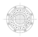
図12は、本発明の第3の実施の形態に係る駆動装置としてのステッピングモータの構成部品を示す分解斜視図である。図13は、組立完成状態におけるステッピングモータの軸方向の構造を示す断面図である。図14は、図13の矢視B−B線に沿うステッピングモータの構造を示す断面図である。
[Third Embodiment]
FIG. 12 is an exploded perspective view showing components of a stepping motor as a drive device according to the third embodiment of the present invention. FIG. 13 is a cross-sectional view showing the axial structure of the stepping motor in the assembled state. FIG. 14 is a cross-sectional view showing the structure of the stepping motor taken along the line BB in FIG.
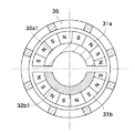
図12乃至図14において、ステッピングモータは、第1のマグネット31a、第2のマグネット31b、第1のステータヨーク32a、第2のステータヨーク32bを備えている。ステッピングモータは、更に、第1のコイル33a、第2のコイル33b、第1の軸受34a、第2の軸受34b、ロータヨーク35を備えている。
12 to 14, the stepping motor includes a
上記第1及び第2の実施の形態では、マグネットの内周部を着磁し、マグネットの内周側に配置したロータヨークを回転させる構成とした。 In the said 1st and 2nd embodiment, it was set as the structure which magnetizes the inner peripheral part of a magnet and rotates the rotor yoke arrange | positioned at the inner peripheral side of the magnet.
これに対し、本実施の形態では、第1のマグネット31a及び第2のマグネット31bの外周部を着磁し、第1のマグネット31a及び第2のマグネット31bの外周側に配置したロータヨーク35を回転させる構成としている。また、本実施の形態では、ステッピングモータを、軸方向に連通した空間部(開口部)を有する円筒状のステータヨーク35を備えた中空円筒形状に構成している。
On the other hand, in the present embodiment, the outer peripheral portions of the
第1のマグネット31aは、外周面をn分割(本実施の形態では16分割)すると共にS極とN極を交互に着磁した仮想マグネットを軸方向に沿って分割したものである。第1のマグネット31aは、ロータヨーク35の中心軸を中心とし、中心角が180°の扇形を底面とする柱に収まるように分割される。
The
第2のマグネット31bは、第1のマグネット31aと同じ形状に構成されている。第2のマグネット31bの着磁パターンは、第1のマグネット31aと同じピッチ且つ同じ強さで周方向に沿って着磁され、第1のマグネット31aに着磁ピッチの1/4だけ(電気角で90°)位相差をつけて配置される。
The
この場合、第1のマグネット31aと第2のマグネット31bの間には、図14に示すように、後述の第1の磁気回路と第2の磁気回路とが干渉しない程度の空隙を設けている。
In this case, as shown in FIG. 14, a gap is provided between the
第1のステータヨーク32aは、軟磁性材料から形成されており、半円筒状の磁極部32a1と円盤状の天板部32a2から構成されている。第1のステータヨーク32aの磁極部32a1の外径は、第1のマグネット31aの内径と略等しく、また、磁極部32a1の外径の弧の長さは、第1のマグネット31aの内径の弧の長さと略等しく設定されている。これにより、第1のステータヨーク32aを第1のマグネット31aの内周を覆うように配置することができる。
The
第2のステータヨーク32bは、第1のステータヨーク32aと同じ形状に構成されている。即ち、第2のステータヨーク32bは、軟磁性材料から形成されており、半円筒状の磁極部32b1と円盤状の天板部32b2から構成されている。第2のステータヨーク32bの磁極部32b1の外径は、第2のマグネット31bの内径と略等しく、また、磁極部32b1の外径の弧の長さは、第2のマグネット31bの内径の弧の長さと略等しく設定されている。これにより、第2のステータヨーク32bを第2のマグネット31bの内周を覆うように配置することができる。
The
第1のコイル33aは、ロータヨーク35の中心軸を中心として導線を多数回巻回することで構成されている。第2のコイル33bは、第1のコイル33aと同様の形状、巻数、抵抗値を有する。
The
第1の軸受34aは、円環形状に構成されており、外径部によりロータヨーク35を回転可能に支持する。第2の軸受34bは、第1の軸受と同じ形状に構成されている。即ち、第2の軸受34bは、円環形状に構成されており、外径部によりロータヨーク35を回転可能に支持する。
The
ロータヨーク35は、軟磁性材料から形成されており、円筒形状に構成されると共に、複数の磁極部351を備えている。即ち、ロータヨーク35の周壁部において軸方向に延出されたスリットを円周方向に周期的(所定間隔)に設けることで、磁極部351として機能させている。ロータヨーク35の磁極部351の本数は、上述した仮想マグネットの磁極数nの半分(本実施の形態では8本)に設定されている。
The
以上、第1のステータヨーク32aに、第1のコイル33a、第1のマグネット31a、第1の軸受34aを固定することで、第1のステータユニットを構成する。また、第2のステータヨーク32bに、第2のコイル33b、第2のマグネット31b、第2の軸受34bを固定することで、第2のステータユニットを構成する。
As described above, the first stator unit is configured by fixing the
本実施の形態のステッピングモータの固定子は、上記の第1のステータユニット及び第2のステータユニット同士をカバーを用いるなど不図示の方法で同心状に固定することで構成している。 The stator of the stepping motor according to the present embodiment is configured by fixing the first stator unit and the second stator unit concentrically by a method (not shown) such as using a cover.
また、本実施の形態のステッピングモータの回転子は、ロータヨーク35を、第1の軸受34aと第2の軸受34bにより回転可能に支持することで構成している。このとき、ロータヨーク35の磁極部351は、第1のマグネット31a及び第2のマグネット31bの着磁面と対向する。
Further, the rotor of the stepping motor according to the present embodiment is configured by rotatably supporting the
本実施の形態においても、上記第1の実施の形態と同様に、第1のコイル33aに通電することで発生した磁束が、第1のマグネット31a、第1のステータヨーク32a、第1の軸受34a、ロータヨーク35と一周する第1の磁気回路を構成する。また、第2のコイル33bに通電することで発生した磁束が、第2のマグネット31b、第2のステータヨーク32b、第2の軸受34b、ロータヨーク35と一周する第2の磁気回路を構成する。
Also in the present embodiment, as in the first embodiment, the magnetic flux generated by energizing the
第1の磁気回路により、ロータヨーク35が第1のマグネット31aの着磁パターンと対向する箇所を励磁する。第2の磁気回路により、ロータヨーク35が第2のマグネット31bの着磁パターンと対向する箇所を励磁する。従って、第1のコイル33aと第2のコイル33bに対する通電方向を順次切り替えることにより、ロータヨーク35の回転方向の安定位置をずらしていくことができる。これにより、ロータヨーク35を第1のマグネット31a及び第2のマグネット31bに対して回転させることができる。
The first magnetic circuit excites the portion where the
次に、本実施の形態のステッピングモータの作用及び効果について説明する。 Next, the operation and effect of the stepping motor of this embodiment will be described.
本実施の形態では、ステッピングモータを、軸方向に連通した空間部(開口部)を有する円筒状のステータヨーク35を備えた中空円筒形状に構成している。これにより、ステータヨーク35の空間部を、レンズの光路、流体の流路、電気の配線などに利用することができる。
In the present embodiment, the stepping motor is configured in a hollow cylindrical shape including a
また、本実施の形態では、外周面を着磁した第1のマグネット31a及び第2のマグネット31bを用いている。ここで、マグネットを着磁する際、マグネットの内周面を着磁する場合は、マグネットの内側に着磁ヨークと着磁コイルを設置しなければならい。そのため、着磁ヨークと着磁コイルを設置できない大きさまでマグネットを小径化することができない。これに対し、マグネットの外周面を着磁する場合は、マグネットの外側に着磁ヨークと着磁コイルを設置する。従って、マグネットを小径化した場合でも着磁ヨークと着磁コイルを設置することができる。
Moreover, in this Embodiment, the
また、マグネットの外周面を着磁する場合は、マグネットの内周面を着磁する場合と比べ太い着磁コイルを用いることができ、マグネットの内周面を着磁する場合よりも強力な着磁を行うことができる。即ち、外周面を着磁したマグネットを利用する構成をとることで、ステッピングモータの小型化及び高効率化が可能となる。 Also, when magnetizing the outer peripheral surface of the magnet, a magnetized coil that is thicker than when magnetizing the inner peripheral surface of the magnet can be used, which is stronger than when magnetizing the inner peripheral surface of the magnet. Magnetism can be performed. That is, the stepping motor can be reduced in size and increased in efficiency by using a configuration in which a magnet having a magnetized outer peripheral surface is used.
以上説明したように、本実施の形態によれば、ステッピングモータにおいて第1の磁気回路の一部と第2の磁気回路の一部を周方向に並べて配置することが可能となる。これにより、従来例のように第1及び第2の磁気回路を軸方向に並べて配置する構成に比べて、ステッピングモータの軸方向の寸法を短縮した短軸化を実現することができる。 As described above, according to the present embodiment, a part of the first magnetic circuit and a part of the second magnetic circuit can be arranged in the circumferential direction in the stepping motor. Thereby, compared with the structure which arrange | positions the 1st and 2nd magnetic circuit along with an axial direction like the prior art example, the short axis | shaft which shortened the dimension of the axial direction of a stepping motor is realizable.
[第4の実施の形態]
図15は、本発明の第4の実施の形態に係る駆動装置としてのステッピングモータの構成部品を示す分解斜視図である。図16は、組立完成状態におけるステッピングモータの軸方向の構造を示す断面図である。図17は、図16の矢視C−C線に沿うステッピングモータの構造を示す断面図である。
[Fourth Embodiment]
FIG. 15 is an exploded perspective view showing components of a stepping motor as a drive device according to the fourth embodiment of the present invention. FIG. 16 is a cross-sectional view showing the axial structure of the stepping motor in the assembled state. FIG. 17 is a cross-sectional view showing the structure of the stepping motor taken along the line CC in FIG.
図15乃至図17において、ステッピングモータは、第1のマグネット41a、第2のマグネット41b、第1のステータヨーク42a、第2のステータヨーク42bを備えている。ステッピングモータは、更に、第1のコイル43a、第2のコイル43b、第1の軸受44a、第2の軸受44b、ロータヨーク45、ステータヨーク連結部材46を備えている。
15 to 17, the stepping motor includes a
上記第1乃至第3の実施の形態では、マグネット、コイル、ステータヨークを固定子として用い、ロータヨークを回転子として用いる構成とした。 In the first to third embodiments, the magnet, coil, and stator yoke are used as the stator, and the rotor yoke is used as the rotor.
これに対し、本実施の形態では、第1のマグネット41a、第2のマグネット41b、第1のステータヨーク42a、第2のステータヨーク42bを回転子として用い、ロータヨーク45、第1のコイル43a、第2のコイル43bを固定子として用いる構成としている。本構成は、上記第1乃至第3の実施の形態と同様の磁気回路により実現することが可能である。
In contrast, in the present embodiment, the
尚、本実施の形態の部品名称の「ロータヨーク」、「ステータヨーク」は、それぞれマグネットに対して「回転する」、「固定する」という意味から名づけている。しかし、実用上の観点からすると、コイルを固定子側に配置させた方が給電を行いやすいため、コイル側を固定子と呼んでいる。本実施の形態においては、コイルはマグネット側だけでなくロータヨーク側に固定する構成も可能である。以下では、コイルと一体に構成されたロータヨークが固定子、コイルに対し回転可能に構成されたステータヨークが回転子として配置される。 The component names “rotor yoke” and “stator yoke” in the present embodiment are named from the meanings of “rotating” and “fixing” with respect to the magnet, respectively. However, from a practical point of view, the coil side is called a stator because it is easier to feed power when the coil is arranged on the stator side. In the present embodiment, the coil may be fixed not only on the magnet side but also on the rotor yoke side. In the following, a rotor yoke integrally formed with the coil is disposed as a stator, and a stator yoke configured to be rotatable with respect to the coil is disposed as a rotor.
第1のマグネット41aは、外周面をn分割(本実施の形態では16分割)すると共にS極とN極を交互に着磁した仮想マグネットを軸方向に沿って分割したものである。第1のマグネット41aは、ロータヨーク45の中心軸を中心とし、中心角が180°の扇形を底面とする柱に収まるように分割される。
The
第2のマグネット41bは、第1のマグネット41aと同じ形状に構成されている。第2のマグネット41bの着磁パターンは、第1のマグネット41aと同じピッチ且つ同じ強さで周方向に沿って着磁され、第1のマグネット41aに着磁ピッチの1/4だけ(電気角で90°)位相差をつけて配置される。
The second magnet 41b is configured in the same shape as the
第1のステータヨーク42aは、軟磁性材料から形成されており、半円筒状の磁極部42a1とシャフト部42a2から構成されている。第1のステータヨーク42aの磁極部42a1の外径は、第1のマグネット41aの内径と略等しく、また、磁極部42a1の外径の弧の長さは、第1のマグネット41aの内径の弧の長さと略等しく設定されている。これにより、第1のステータヨーク42aを第1のマグネット41aの内周を覆うように配置することができる。
The
第2のステータヨーク42bは、第1のステータヨーク42aと同じ形状に構成されている。即ち、第2のステータヨーク42bは、軟磁性材料から形成されており、半円筒状の磁極部42b1とシャフト部42b2から構成されている。第2のステータヨーク42bの磁極部42b1の外径は、第2のマグネット41bの内径と略等しく、また、磁極部42b1の外径の弧の長さは、第2のマグネット41bの内径の弧の長さと略等しく設定されている。これにより、第2のステータヨーク42bを第2のマグネット41bの内周を覆うように配置することができる。
The
ステータヨーク連結部材46は、非磁性材料から形成されており、円柱形状に構成されると共に、2箇所の位置決め部461を備えている。ステータヨーク連結部材46の位置決め部461は、ステータヨーク連結部材46の外周部から径方向に延出されている。これにより、ステータヨーク連結部材46の位置決め部461は、第1のステータヨーク42aと第2のステータヨーク42bを同軸に所定の位相差で固定することができる。
The stator
ステータヨーク連結部材46の位置決め部461は、図17に示すように第1のステータヨーク42aと第2のステータヨーク42bの外側にまで延出されている。これにより、ステータヨーク連結部材46の位置決め部461は、第1のマグネット41aと第2のマグネット41bを同軸に所定の位相差で固定することができる。
As shown in FIG. 17, the
第1のコイル43aは、ステータヨーク45の中心軸を中心として導線を多数回巻回することで構成されている。第2のコイル43bは、第1のコイル43aと同様の形状、巻数、抵抗値を有する。
The
第1の軸受44aは、軟磁性材料から形成されており、円盤形状に構成されている。第1の軸受44aの外径は、ロータヨーク45の内径と略同じ寸法に設定されている。また、第1の軸受44aは、中心に第1のステータヨーク42aのシャフト部42a2を回転可能に支持する穴部を有する。
The
第2の軸受44bは、第1の軸受44aと同じ形状に構成されている。即ち、第2の軸受44bは、軟磁性材料から形成されており、円盤形状に構成されている。第2の軸受44bの外径は、ロータヨーク45の内径と略同じ寸法に設定されている。また、第2の軸受44bは、中心に第2のステータヨーク42bのシャフト部42b2を回転可能に支持する穴部を有する。
The
ロータヨーク45は、軟磁性材料から形成されており、円筒形状に構成されると共に、複数の磁極部451を備えている。即ち、ロータヨーク45の周壁部において軸方向に延出されたスリットを円周方向に周期的(所定間隔)に設けることで、磁極部451として機能させている。ロータヨーク45の磁極部451の本数は、上述した仮想マグネットの磁極数nの半分(本実施の形態では8本)に設定されている。
The
本実施の形態のステッピングモータの固定子は、ロータヨーク45に、第1のコイル43a、第1の軸受44a、第2のコイル43b、第2の軸受44bを固定することで構成している。
The stator of the stepping motor according to the present embodiment is configured by fixing the
また、本実施の形態のステッピングモータの回転子は、ステータヨーク連結部材46に、第1のステータヨーク42a、第2のステータヨーク42b、第1のマグネット41a、第2のマグネット41bを同軸に固定することで構成している。
Further, in the rotor of the stepping motor of the present embodiment, the
ステッピングモータの回転子は、固定子に対して回転可能に支持され、ロータヨーク45の磁極部451は、第1のマグネット41a及び第2のマグネット41bの着磁面と対向する。
The rotor of the stepping motor is supported rotatably with respect to the stator, and the
本実施の形態のステッピングモータでは、第1のコイル43aに通電することで発生する磁束は、第1のステータヨーク42aの磁極部42a1、シャフト部42a2、第1の軸受44a、ロータヨーク45と一周する第1の磁気回路を構成する。また、第2のコイル43bに通電することで発生する磁束は、第2のステータヨーク42bの磁極部42b1、シャフト部42b2、第2の軸受44b、ロータヨーク45と一周する第2の磁気回路を構成する。
In the stepping motor of the present embodiment, the magnetic flux generated by energizing the
第1の磁気回路により、ロータヨーク45における第1のマグネット41aの着磁パターンと対向する箇所を励磁し、第2の磁気回路により、ロータヨーク45における第2のマグネット41bの着磁パターンと対向する箇所を励磁することができる。
A portion of the
従って、第1のコイル43aと第2のコイル43bに対する通電方向を順次切り替えることにより、ロータヨーク45の回転方向の安定位置を(180/n)°ずつずらしていくことができる。これにより、第1のマグネット41a及び第2のマグネット41bで構成される回転子を、ロータヨーク45で構成される固定子に対して回転させることができる。その様子を、図17乃至図20に示す。
Therefore, the stable position in the rotational direction of the
このように、本実施の形態では、第1及び第2のコイル43a、43bをロータヨーク45側に固定し、第1及び第2のマグネット41a、41bと第1及び第2のステータヨーク42a、42bを回転子とする構成としている。
Thus, in this embodiment, the first and
次に、本実施の形態のステッピングモータの作用及び効果について説明する。 Next, the operation and effect of the stepping motor of this embodiment will be described.
本実施の形態では、ステッピングモータを上記構成とすることで、外周面を着磁したマグネットを利用することができる。これにより、上記第3の実施の形態と同様に、内周面を着磁したマグネットに比べてマグネットの小径化が可能となると共に、より強力な着磁を行うことができるという利点がある。 In the present embodiment, a magnet having an outer peripheral surface magnetized can be used by configuring the stepping motor as described above. As a result, similar to the third embodiment, the magnet can be made smaller in diameter than the magnet having the inner peripheral surface magnetized, and there is an advantage that stronger magnetization can be performed.
また、上記第1の実施の形態では、ステッピングモータの力の発生箇所がマグネットの内周部とロータヨークの外周部の間となるように構成した。 Moreover, in the said 1st Embodiment, it comprised so that the generation | occurrence | production location of the force of a stepping motor might be between the inner peripheral part of a magnet, and the outer peripheral part of a rotor yoke.
これに対し、本実施の形態では、ステッピングモータの力の発生箇所が第1のマグネット41a及び第2のマグネット41bの外周部とロータヨーク45の間となるように構成している。このため、ステッピングモータの外径を等しくした場合、本実施の形態の構成の方が力の発生する箇所の、中心軸からの径が大きくなる。これにより、本実施の形態の構成の方がより大きなトルクを発生することができる。
On the other hand, in the present embodiment, the position where the force of the stepping motor is generated is configured to be between the outer peripheral portions of the
以上説明したように、本実施の形態によれば、ステッピングモータにおいて第1の磁気回路の一部と第2の磁気回路の一部を周方向に並べて配置することが可能となる。これにより、従来例のように第1及び第2の磁気回路を軸方向に並べて配置する構成に比べて、ステッピングモータの軸方向の寸法を短縮した短軸化を実現することができる。 As described above, according to the present embodiment, a part of the first magnetic circuit and a part of the second magnetic circuit can be arranged in the circumferential direction in the stepping motor. Thereby, compared with the structure which arrange | positions the 1st and 2nd magnetic circuit along with an axial direction like the prior art example, the short axis | shaft which shortened the dimension of the axial direction of a stepping motor is realizable.
[他の実施の形態]
上記第1乃至第4の実施の形態では、ステッピングモータ単体について説明したが、ステッピングモータを撮像装置に搭載して駆動源として用いるなど、各種の応用が可能である。
[Other embodiments]
In the first to fourth embodiments, the single stepping motor has been described. However, various applications such as mounting a stepping motor in an imaging apparatus and using it as a drive source are possible.
11a、31a、41a 第1のマグネット
11b、31b、41b 第2のマグネット
12a、22a、32a、42a 第1のステータヨーク
12b、22b、32b、42b 第2のステータヨーク
13a、33a、43a 第1のコイル
13b、33b、43b 第2のコイル
14a、34a、44a 第1の軸受
14b、34b、44b 第2の軸受
15、25、35、45 ロータヨーク
21 マグネット
46 ステータヨーク連結部材
11a, 31a,
Claims (5)
前記ロータヨークの前記磁極部に対向するように配置されるものであって、円弧形状を有し、内周面に周方向に沿って交互に異なる磁極が着磁された第1のマグネットと、
前記第1のマグネットの外周面に接するように配置されるものであって、前記ロータヨークのシャフト部の一方端を回転可能に軸支する第1のステータヨークと、
前記第1のステータヨークを介して、前記ロータヨークの磁極部を励磁する第1のコイルと、
前記ロータヨークの前記磁極部に対向するように配置されるものであって、円弧形状を有し、内周面に周方向に沿って交互に異なる磁極が着磁された第2のマグネットと、
前記第2のマグネットの外周面に接するように配置されるものであって、前記ロータヨークのシャフト部の他方端を回転可能に軸支する第2のステータヨークと、
前記第2のステータヨークを介して、前記ロータヨークの磁極部を励磁する第2のコイルとを備え、
前記第1のマグネットと前記第2のマグネットは前記ロータヨークの径方向にて互いに向かい合うように配置され、前記第1のマグネットと前記第2のマグネットとの間に前記ロータヨークが配置され、前記第1のマグネットの磁極に対して前記第2のマグネットの磁極が所定の位相差を持つように、前記第1のマグネットと前記第2のマグネットとは配置されることを特徴とする駆動装置。 A rotor yoke having a shaft portion and a plurality of magnetic pole portions protruding radially from the shaft portion;
Be one that is arranged to face the magnetic pole portion of the rotor yoke has an arcuate shape, a first magnet magnetic poles different alternately in the inner peripheral surface along a circumferential direction are magnetized,
A first stator yoke that is arranged so as to be in contact with an outer peripheral surface of the first magnet, and rotatably supports one end of a shaft portion of the rotor yoke;
A first coil that excites a magnetic pole portion of the rotor yoke via the first stator yoke;
Be one that is arranged to face the magnetic pole portion of the rotor yoke has a circular arc shape, and a second magnet poles different alternately in the inner peripheral surface along a circumferential direction are magnetized,
A second stator yoke that is disposed in contact with the outer peripheral surface of the second magnet and rotatably supports the other end of the shaft portion of the rotor yoke;
A second coil that excites the magnetic pole part of the rotor yoke via the second stator yoke,
Wherein the first magnet second magnet is disposed so as to face each other in the radial direction of the rotor yoke, the rotor yoke is disposed between the first magnet and said second magnet, said first the like poles of the second magnet relative to the magnetic poles of the magnet has a predetermined phase difference, the driving apparatus characterized by being arranged between said first magnet and said second magnet.
前記ロータヨークの前記磁極部に対向するように配置されるものであって、円筒形状を有し、内周面が周方向に沿って複数の領域に分割され、該分割された領域は第1の着磁パターンもしくは第2の着磁パターンで着磁され、且つ該分割された領域の間には非着磁部が形成されるマグネットと、
前記第1の着磁パターンで着磁された前記マグネットの分割された領域に接するように配置されるものであって、前記ロータヨークのシャフト部の一方端を回転可能に軸支する第1のステータヨークと、
前記第1のステータヨークを介して、前記ロータヨークの磁極部を励磁する第1のコイルと、
前記第2の着磁パターンで着磁された前記マグネットの分割された領域に接するように配置されるものであって、前記ロータヨークのシャフト部の他方端を回転可能に軸支する第2のステータヨークと、
前記第2のステータヨークを介して、前記ロータヨークの磁極部を励磁する第2のコイルとを備え、
前記第1の着磁パターンで着磁された領域同士が前記ロータヨークの径方向にて互いに向かい合うように配置されるとともに、前記第2の着磁パターンで着磁された領域同士が前記ロータヨークの径方向にて互いに向かい合うように配置され、前記マグネットの内側に前記ロータヨークが配置され、前記第1の着磁パターンと前記第2の着磁パターンとが所定の位相差を持つように、前記マグネットの分割された領域は着磁されることを特徴とする駆動装置。 A rotor yoke having a shaft portion and a plurality of magnetic pole portions protruding radially from the shaft portion;
The rotor yoke is disposed so as to face the magnetic pole portion, has a cylindrical shape, and an inner peripheral surface is divided into a plurality of regions along a circumferential direction , and the divided regions are the first regions. is magnetized by the magnetizing pattern or a second magnetization pattern, and between the divided regions and magnet non magnetized portion is formed,
It is those that are arranged in contact with the divided regions of the magnet that is magnetized in the first magnetization pattern, a first stator that rotatably supports one end of the shaft portion of the rotor yoke York,
A first coil that excites a magnetic pole portion of the rotor yoke via the first stator yoke;
It is those that are arranged in contact with the divided regions of the magnet that is magnetized by the second magnetization pattern, the second stator that rotatably supports the other end of the shaft portion of the rotor yoke York,
A second coil that excites the magnetic pole part of the rotor yoke via the second stator yoke,
Diameter of the first magnetization pattern magnetized regions each other are arranged so as to face each other in the radial direction of the rotor yoke in Rutotomoni, the second magnetized region between said rotor yoke in magnetization pattern The rotor yoke is disposed inside the magnet, and the first magnetizing pattern and the second magnetizing pattern have a predetermined phase difference so as to have a predetermined phase difference. A drive device characterized in that the divided area is magnetized.
前記ロータヨークの内側で、前記ロータヨークの前記磁極部に対向するように配置されるものであって、円弧形状を有し、外周面に周方向に沿って交互に異なる磁極が着磁された第1のマグネットと、
前記第1のマグネットの内周面に接するように配置されるものであって、前記ロータヨークの一方端を回転可能に軸支する第1のステータヨークと、
前記第1のステータヨークを介して、前記ロータヨークの磁極部を励磁する第1のコイルと、
前記ロータヨークの内側で、前記ロータヨークの前記磁極部に対向するように配置されるものであって、円弧形状を有し、外周面に周方向に沿って交互に異なる磁極が着磁された第2のマグネットと、
前記第2のマグネットの内周面に接するように配置されるものであって、前記ロータヨークの他方端を回転可能に軸支する第2のステータヨークと、
前記第2のステータヨークを介して、前記ロータヨークの磁極部を励磁する第2のコイルとを備え、
前記第1のマグネットと前記第2のマグネットとは前記ロータヨークの径方向にて互いに向かい合うように配置され、前記第1のマグネットの磁極に対して前記第2のマグネットの磁極が所定の位相差を持つように、前記第1のマグネットと前記第2のマグネットとは配置されることを特徴とする駆動装置。 A rotor yoke having a cylindrical shape and having a plurality of magnetic pole portions formed in the circumferential direction along the circumferential direction ;
Inside said rotor yoke, there is disposed so as to face the magnetic pole portion of the rotor yoke, has an arc shape, first the different magnetic poles alternately on the outer circumferential surface along the circumferential direction are magnetized Magnets,
A first stator yoke that is disposed in contact with an inner peripheral surface of the first magnet and rotatably supports one end of the rotor yoke ;
A first coil that excites a magnetic pole portion of the rotor yoke via the first stator yoke;
Inside said rotor yoke, there is disposed so as to face the magnetic pole portion of the rotor yoke has a circular arc shape, a second different magnetic poles alternately on the outer circumferential surface along the circumferential direction are magnetized Magnets,
A second stator yoke that is disposed so as to contact an inner peripheral surface of the second magnet, and rotatably supports the other end of the rotor yoke;
A second coil that excites the magnetic pole part of the rotor yoke via the second stator yoke,
The first magnet and the second magnet are arranged to face each other in the radial direction of the rotor yoke, and the magnetic pole of the second magnet has a predetermined phase difference with respect to the magnetic pole of the first magnet. having as the drive apparatus characterized by being arranged between said first magnet and said second magnet.
前記ロータヨークの前記磁極部に対向するように配置されるものであって、円弧形状を有し、外周面に周方向に沿って交互に異なる磁極が着磁された第1のマグネットと、
前記第1のマグネットの内周面を覆う第1の磁極部、及び前記ロータヨークに対して回転可能に支持されるシャフト部が形成された第1のステータヨークと、
前記第1のステータヨークを介して、前記ロータヨークの磁極部を励磁する第1のコイルと、
前記ロータヨークの前記磁極部に対向するように配置されるものであって、円弧形状を有し、外周面に周方向に沿って交互に異なる磁極が着磁された第2のマグネットと、
前記第2のマグネットの内周面を覆う第2の磁極部、及び前記ロータヨークに対して回転可能に支持されるシャフト部が形成された第2のステータヨークと、
前記第2のステータヨークを介して、前記ロータヨークの磁極部を励磁する第2のコイルと、
前記第1の磁極部の内周面と前記第2の磁極部の内周面とが互いに向かい合うように、前記第1のステータヨークと前記第2のステータヨークとを連結するものであって、非磁性材料で形成される連結部材とを備え、
前記ロータヨークに前記第1および第2のコイルが固定され、前記ロータヨークは前記連結部材にて連結される前記第1および第2のステータヨークを回転可能に軸支し、前記第1のマグネットの磁極に対して前記第2のマグネットの磁極が所定の位相差を持つように、前記第1のマグネットと前記第2のマグネットとは配置されることを特徴とする駆動装置。 A rotor yoke having a cylindrical shape and having a plurality of magnetic pole portions formed along the circumferential direction on the circumferential surface;
Be one that is arranged to face the magnetic pole portion of the rotor yoke has an arcuate shape, a first magnet having different magnetic poles alternately on the outer circumferential surface along the circumferential direction are magnetized,
A first magnetic pole portion covering an inner peripheral surface of the first magnet, and a first stator yoke having a shaft portion rotatably supported with respect to the rotor yoke;
A first coil that excites a magnetic pole portion of the rotor yoke via the first stator yoke;
Be one that is arranged to face the magnetic pole portion of the rotor yoke has a circular arc shape, and a second magnet having different magnetic poles alternately on the outer circumferential surface along the circumferential direction are magnetized,
A second magnetic pole portion covering the inner peripheral surface of the second magnet, and a second stator yoke formed with a shaft portion rotatably supported with respect to the rotor yoke;
A second coil for exciting the magnetic pole portion of the rotor yoke via the second stator yoke;
The first magnetic pole portion inner peripheral surface and to face the second magnetic pole portion inner and peripheral surfaces to each other in, there is for connecting the said first stator yoke and the second stator yoke, A connecting member formed of a non-magnetic material,
The first and second coils are fixed to the rotor yoke, the rotor yoke rotatably supports the first and second stator yokes connected by the connecting member, and the magnetic poles of the first magnet wherein as the magnetic poles of the second magnet has a predetermined phase difference, the driving apparatus characterized by is disposed between said first magnet and said second magnet relative.
Priority Applications (2)
| Application Number | Priority Date | Filing Date | Title |
|---|---|---|---|
| JP2006175210A JP4878226B2 (en) | 2006-06-26 | 2006-06-26 | Drive device |
| US11/766,842 US7626291B2 (en) | 2006-06-26 | 2007-06-22 | Drive apparatus |
Applications Claiming Priority (1)
| Application Number | Priority Date | Filing Date | Title |
|---|---|---|---|
| JP2006175210A JP4878226B2 (en) | 2006-06-26 | 2006-06-26 | Drive device |
Publications (3)
| Publication Number | Publication Date |
|---|---|
| JP2008005670A JP2008005670A (en) | 2008-01-10 |
| JP2008005670A5 JP2008005670A5 (en) | 2011-03-10 |
| JP4878226B2 true JP4878226B2 (en) | 2012-02-15 |
Family
ID=38872897
Family Applications (1)
| Application Number | Title | Priority Date | Filing Date |
|---|---|---|---|
| JP2006175210A Expired - Fee Related JP4878226B2 (en) | 2006-06-26 | 2006-06-26 | Drive device |
Country Status (2)
| Country | Link |
|---|---|
| US (1) | US7626291B2 (en) |
| JP (1) | JP4878226B2 (en) |
Families Citing this family (8)
| Publication number | Priority date | Publication date | Assignee | Title |
|---|---|---|---|---|
| JP4378327B2 (en) * | 2005-07-28 | 2009-12-02 | キヤノン株式会社 | Drive device |
| JP4295329B2 (en) * | 2007-03-30 | 2009-07-15 | ミネベアモータ株式会社 | Stepping motor |
| US20090046421A1 (en) * | 2007-08-15 | 2009-02-19 | Richard Sohaney | System and Method for Reducing Information Handling System Cooling Fan Noise |
| US8598758B2 (en) * | 2009-07-16 | 2013-12-03 | Cameron International Corporation | Electric motor and position holding device for such an electric motor |
| CN102712068B (en) * | 2009-10-16 | 2015-01-07 | 韦斯有限公司 | Rotary indexing table |
| US9719607B2 (en) * | 2012-09-10 | 2017-08-01 | Cameron International Corporation | Magnetic holding brake and actuator with a magnetic holding brake |
| CN105006334B (en) * | 2015-06-23 | 2017-08-18 | 歌尔股份有限公司 | Multipath magnetic circuit magnetizes technique |
| KR102622136B1 (en) * | 2016-11-07 | 2024-01-08 | 현대모비스 주식회사 | motor with types of segmented rotor |
Family Cites Families (11)
| Publication number | Priority date | Publication date | Assignee | Title |
|---|---|---|---|---|
| GB1199155A (en) * | 1966-10-31 | 1970-07-15 | Plessey Co Ltd | Improvements in or relating to Rotary Electric Machines |
| JPS63686U (en) * | 1986-06-20 | 1988-01-06 | ||
| JPS6458288A (en) * | 1987-08-31 | 1989-03-06 | Takara Co Ltd | Engine-travelling toy |
| JPH06261506A (en) * | 1993-03-09 | 1994-09-16 | Nisca Corp | Stepping motor |
| JP3133270B2 (en) | 1996-04-08 | 2001-02-05 | キヤノン株式会社 | Motor and feeding device |
| EP0851560B1 (en) * | 1996-12-27 | 2001-10-31 | Canon Kabushiki Kaisha | Compact stepping motor |
| JP3548425B2 (en) * | 1998-04-17 | 2004-07-28 | キヤノン株式会社 | motor |
| JP2002051526A (en) | 2000-07-31 | 2002-02-15 | Canon Inc | Motor |
| JP2005033860A (en) * | 2003-07-08 | 2005-02-03 | Minebea Co Ltd | Structure of claw-pole stepping motor |
| JP4272075B2 (en) | 2004-01-16 | 2009-06-03 | ミネベア株式会社 | Stepping motor |
| JP4387858B2 (en) * | 2004-04-14 | 2009-12-24 | キヤノン株式会社 | Stepping motor |
-
2006
- 2006-06-26 JP JP2006175210A patent/JP4878226B2/en not_active Expired - Fee Related
-
2007
- 2007-06-22 US US11/766,842 patent/US7626291B2/en not_active Expired - Fee Related
Also Published As
| Publication number | Publication date |
|---|---|
| JP2008005670A (en) | 2008-01-10 |
| US7626291B2 (en) | 2009-12-01 |
| US20070296312A1 (en) | 2007-12-27 |
Similar Documents
| Publication | Publication Date | Title |
|---|---|---|
| JP4878226B2 (en) | Drive device | |
| JP2007267565A (en) | Coreless motor | |
| US9705391B2 (en) | Stepping motor, lens apparatus, and image pickup apparatus | |
| US6713936B2 (en) | Stepping motor | |
| EP1445851B1 (en) | Motor | |
| JP4748649B2 (en) | Drive device | |
| JP2009195055A (en) | Rotating electric machine | |
| JP2005295756A (en) | Motor and optical device | |
| US20030234586A1 (en) | Stepping motor | |
| JP7043824B2 (en) | Spindle motor and disk drive equipped with it | |
| JP2013183511A (en) | Actuator | |
| JP2007037244A (en) | Driver | |
| US20030107274A1 (en) | Stepping motor | |
| JP2007116850A (en) | Permanent-magnet rotating electric machine and cylindrical linear motor | |
| JP4047317B2 (en) | Stepping motor | |
| JP5126464B2 (en) | Stepping motor and camera focus adjustment actuator | |
| JP2007143253A (en) | Stepping motor | |
| JP2005121801A (en) | Driving device, light quantity adjusting device and lens-driving device | |
| JP2005143207A (en) | Stepping motor | |
| JPH0678506A (en) | Radial type outer rotor type brushless motor | |
| JP2020089101A (en) | Motor and motor drive device | |
| KR101006932B1 (en) | Stepping motor | |
| JP2023040667A (en) | motor | |
| JP2006280105A (en) | Driving device | |
| JP2008278660A (en) | Outer rotor type motor |
Legal Events
| Date | Code | Title | Description |
|---|---|---|---|
| A521 | Written amendment |
Free format text: JAPANESE INTERMEDIATE CODE: A523 Effective date: 20090624 |
|
| A621 | Written request for application examination |
Free format text: JAPANESE INTERMEDIATE CODE: A621 Effective date: 20090624 |
|
| A521 | Written amendment |
Free format text: JAPANESE INTERMEDIATE CODE: A523 Effective date: 20110120 |
|
| A977 | Report on retrieval |
Free format text: JAPANESE INTERMEDIATE CODE: A971007 Effective date: 20111110 |
|
| TRDD | Decision of grant or rejection written | ||
| A01 | Written decision to grant a patent or to grant a registration (utility model) |
Free format text: JAPANESE INTERMEDIATE CODE: A01 Effective date: 20111122 |
|
| A01 | Written decision to grant a patent or to grant a registration (utility model) |
Free format text: JAPANESE INTERMEDIATE CODE: A01 |
|
| A61 | First payment of annual fees (during grant procedure) |
Free format text: JAPANESE INTERMEDIATE CODE: A61 Effective date: 20111125 |
|
| FPAY | Renewal fee payment (event date is renewal date of database) |
Free format text: PAYMENT UNTIL: 20141209 Year of fee payment: 3 |
|
| LAPS | Cancellation because of no payment of annual fees |