JP4875416B2 - Medical guide system - Google Patents
Medical guide system Download PDFInfo
- Publication number
- JP4875416B2 JP4875416B2 JP2006177191A JP2006177191A JP4875416B2 JP 4875416 B2 JP4875416 B2 JP 4875416B2 JP 2006177191 A JP2006177191 A JP 2006177191A JP 2006177191 A JP2006177191 A JP 2006177191A JP 4875416 B2 JP4875416 B2 JP 4875416B2
- Authority
- JP
- Japan
- Prior art keywords
- organ
- image data
- medical
- image
- subject
- Prior art date
- Legal status (The legal status is an assumption and is not a legal conclusion. Google has not performed a legal analysis and makes no representation as to the accuracy of the status listed.)
- Expired - Fee Related
Links
Images


Classifications
-
- A—HUMAN NECESSITIES
- A61—MEDICAL OR VETERINARY SCIENCE; HYGIENE
- A61B—DIAGNOSIS; SURGERY; IDENTIFICATION
- A61B8/00—Diagnosis using ultrasonic, sonic or infrasonic waves
- A61B8/42—Details of probe positioning or probe attachment to the patient
- A61B8/4245—Details of probe positioning or probe attachment to the patient involving determining the position of the probe, e.g. with respect to an external reference frame or to the patient
- A61B8/4254—Details of probe positioning or probe attachment to the patient involving determining the position of the probe, e.g. with respect to an external reference frame or to the patient using sensors mounted on the probe
-
- A—HUMAN NECESSITIES
- A61—MEDICAL OR VETERINARY SCIENCE; HYGIENE
- A61B—DIAGNOSIS; SURGERY; IDENTIFICATION
- A61B34/00—Computer-aided surgery; Manipulators or robots specially adapted for use in surgery
- A61B34/20—Surgical navigation systems; Devices for tracking or guiding surgical instruments, e.g. for frameless stereotaxis
-
- A—HUMAN NECESSITIES
- A61—MEDICAL OR VETERINARY SCIENCE; HYGIENE
- A61B—DIAGNOSIS; SURGERY; IDENTIFICATION
- A61B5/00—Measuring for diagnostic purposes; Identification of persons
- A61B5/06—Devices, other than using radiation, for detecting or locating foreign bodies ; Determining position of diagnostic devices within or on the body of the patient
- A61B5/065—Determining position of the probe employing exclusively positioning means located on or in the probe, e.g. using position sensors arranged on the probe
-
- A—HUMAN NECESSITIES
- A61—MEDICAL OR VETERINARY SCIENCE; HYGIENE
- A61B—DIAGNOSIS; SURGERY; IDENTIFICATION
- A61B90/00—Instruments, implements or accessories specially adapted for surgery or diagnosis and not covered by any of the groups A61B1/00 - A61B50/00, e.g. for luxation treatment or for protecting wound edges
- A61B90/36—Image-producing devices or illumination devices not otherwise provided for
-
- A—HUMAN NECESSITIES
- A61—MEDICAL OR VETERINARY SCIENCE; HYGIENE
- A61B—DIAGNOSIS; SURGERY; IDENTIFICATION
- A61B90/00—Instruments, implements or accessories specially adapted for surgery or diagnosis and not covered by any of the groups A61B1/00 - A61B50/00, e.g. for luxation treatment or for protecting wound edges
- A61B90/90—Identification means for patients or instruments, e.g. tags
- A61B90/98—Identification means for patients or instruments, e.g. tags using electromagnetic means, e.g. transponders
-
- A—HUMAN NECESSITIES
- A61—MEDICAL OR VETERINARY SCIENCE; HYGIENE
- A61B—DIAGNOSIS; SURGERY; IDENTIFICATION
- A61B34/00—Computer-aided surgery; Manipulators or robots specially adapted for use in surgery
- A61B34/20—Surgical navigation systems; Devices for tracking or guiding surgical instruments, e.g. for frameless stereotaxis
- A61B2034/2046—Tracking techniques
- A61B2034/2051—Electromagnetic tracking systems
-
- A—HUMAN NECESSITIES
- A61—MEDICAL OR VETERINARY SCIENCE; HYGIENE
- A61B—DIAGNOSIS; SURGERY; IDENTIFICATION
- A61B90/00—Instruments, implements or accessories specially adapted for surgery or diagnosis and not covered by any of the groups A61B1/00 - A61B50/00, e.g. for luxation treatment or for protecting wound edges
- A61B90/36—Image-producing devices or illumination devices not otherwise provided for
- A61B2090/364—Correlation of different images or relation of image positions in respect to the body
-
- A—HUMAN NECESSITIES
- A61—MEDICAL OR VETERINARY SCIENCE; HYGIENE
- A61B—DIAGNOSIS; SURGERY; IDENTIFICATION
- A61B90/00—Instruments, implements or accessories specially adapted for surgery or diagnosis and not covered by any of the groups A61B1/00 - A61B50/00, e.g. for luxation treatment or for protecting wound edges
- A61B90/36—Image-producing devices or illumination devices not otherwise provided for
- A61B90/37—Surgical systems with images on a monitor during operation
- A61B2090/378—Surgical systems with images on a monitor during operation using ultrasound
-
- A—HUMAN NECESSITIES
- A61—MEDICAL OR VETERINARY SCIENCE; HYGIENE
- A61B—DIAGNOSIS; SURGERY; IDENTIFICATION
- A61B90/00—Instruments, implements or accessories specially adapted for surgery or diagnosis and not covered by any of the groups A61B1/00 - A61B50/00, e.g. for luxation treatment or for protecting wound edges
- A61B90/39—Markers, e.g. radio-opaque or breast lesions markers
- A61B2090/397—Markers, e.g. radio-opaque or breast lesions markers electromagnetic other than visible, e.g. microwave
-
- A—HUMAN NECESSITIES
- A61—MEDICAL OR VETERINARY SCIENCE; HYGIENE
- A61B—DIAGNOSIS; SURGERY; IDENTIFICATION
- A61B5/00—Measuring for diagnostic purposes; Identification of persons
- A61B5/06—Devices, other than using radiation, for detecting or locating foreign bodies ; Determining position of diagnostic devices within or on the body of the patient
-
- A—HUMAN NECESSITIES
- A61—MEDICAL OR VETERINARY SCIENCE; HYGIENE
- A61B—DIAGNOSIS; SURGERY; IDENTIFICATION
- A61B8/00—Diagnosis using ultrasonic, sonic or infrasonic waves
- A61B8/12—Diagnosis using ultrasonic, sonic or infrasonic waves in body cavities or body tracts, e.g. by using catheters
Landscapes
- Health & Medical Sciences (AREA)
- Life Sciences & Earth Sciences (AREA)
- Surgery (AREA)
- Engineering & Computer Science (AREA)
- Public Health (AREA)
- Biomedical Technology (AREA)
- Heart & Thoracic Surgery (AREA)
- Medical Informatics (AREA)
- Molecular Biology (AREA)
- Animal Behavior & Ethology (AREA)
- General Health & Medical Sciences (AREA)
- Veterinary Medicine (AREA)
- Pathology (AREA)
- Nuclear Medicine, Radiotherapy & Molecular Imaging (AREA)
- Physics & Mathematics (AREA)
- Biophysics (AREA)
- Oral & Maxillofacial Surgery (AREA)
- Robotics (AREA)
- Radiology & Medical Imaging (AREA)
- Human Computer Interaction (AREA)
- Electromagnetism (AREA)
- Ultra Sonic Daignosis Equipment (AREA)
- Apparatus For Radiation Diagnosis (AREA)
- Endoscopes (AREA)
- Image Processing (AREA)
- Image Analysis (AREA)
- Electrotherapy Devices (AREA)
Abstract
Description
本発明は、医用画像を用いて医用器具のガイドを行う医用ガイドシステムに関する。 The present invention relates to a medical guide system that guides a medical instrument using a medical image.
超音波内視鏡検査や腹腔鏡手術を行う際に、術者は、予め生体内の各器官、各組織の既知の解剖学的な位置関係を念頭に置きながら、現在観察している解剖学上の位置を推定して、診断や手術を行っている。このような診断や手術を支援するために、検査時や手術時に観察している位置を案内するガイド画像を、事前に取得したCT画像やMRI画像をもとに合成して表示する技術が提案されている。 When performing endoscopic ultrasound or laparoscopic surgery, the surgeon is currently observing the anatomy currently being observed, keeping in mind the known anatomical positional relationships of each organ and tissue in the body. The upper position is estimated to perform diagnosis and surgery. In order to support such diagnosis and surgery, a technique for combining and displaying a guide image that guides the position observed at the time of examination or surgery based on CT images and MRI images acquired in advance is proposed. Has been.
このような医用ガイド装置の一例として、特開平10−151131号公報には、超音波プローブの位置を検出し、超音波画像の断層位置に対応する断層像を画像データから得て、超音波画像と並べて、若しくは重ねて、又は一定時間間隔で交互に、表示する医用ガイド装置が記載されている。 As an example of such a medical guide apparatus, Japanese Patent Application Laid-Open No. 10-151131 discloses a position of an ultrasonic probe, a tomographic image corresponding to a tomographic position of an ultrasonic image is obtained from image data, and an ultrasonic image is obtained. Medical guide devices that display side by side, overlaid, or alternately at regular time intervals are described.
また、特開2005−312770号公報には、超音波内視鏡の先端位置を検出して、超音波内視鏡の解剖学的な位置に対応したガイド画像を解剖学的画像データに基づき構築し表示する医用ガイド装置が記載されている。 Japanese Patent Application Laid-Open No. 2005-31770 detects the tip position of an ultrasonic endoscope and constructs a guide image corresponding to the anatomical position of the ultrasonic endoscope based on anatomical image data. A medical guide device for displaying and displaying is described.
さらに、特開2004−113629号公報には、超音波プローブの走査面の位置と方位とを検出することによって、正確なガイド画像を表示する技術が記載されている。 Furthermore, Japanese Patent Application Laid-Open No. 2004-113629 describes a technique for displaying an accurate guide image by detecting the position and orientation of the scanning surface of an ultrasonic probe.
加えて、特開2002−345725号公報には、事前に撮影して得た医用画像データから3次元臓器モデル画像を生成し、さらにこの3次元臓器モデルを臓器の単位時間当たりの変動量に応じて順次補正し、内視鏡先端位置を検出することによって、内視鏡先端位置に相当する3次元モデル画像を表示する医用ガイド装置が記載されている。
ところで、事前に(医用器具を使用する以前に)画像データを取得するためのCTやMRIは、通常は被検者を仰臥位にした状態において撮影される。これに対して、医用器具である内視鏡や超音波内視鏡等を用いた検査や手術等は、被検者を左側臥位や腹臥位にした状態で行われる。しかし、仰臥位と、左側臥位や腹臥位とでは、体に対する重力の方向が異なるために、体腔内における臓器や血管の位置関係が変化してしまうことになる。従って、被検者を仰臥位にして撮影されたCT画像やMRI画像に基づき内視鏡検査時の画像取得位置に対して作成されたガイド画像は、内視鏡検査により得られる内視鏡画像や超音波画像とは体腔内における臓器位置が異なることになってしまう。 By the way, CT or MRI for acquiring image data in advance (before using a medical instrument) is usually taken in a state where the subject is in a supine position. On the other hand, examinations and operations using a medical instrument such as an endoscope or an ultrasonic endoscope are performed in a state where the subject is in the left-side prone position or the prone position. However, the position of the organs and blood vessels in the body cavity changes because the direction of gravity relative to the body differs between the supine position and the left-side or prone position. Therefore, the guide image created for the image acquisition position at the time of endoscopy based on the CT image or MRI image taken with the subject in the supine position is an endoscopic image obtained by endoscopy. The position of the organ in the body cavity is different from the ultrasonic image.
また、上述した例に限らず、腹腔鏡や体外式の超音波診断装置を用いる場合にも、体位が仰臥位でない場合には、上述したような事情は同様に生じる。 Further, not only in the above-described example, but also in the case where a laparoscope or an extracorporeal ultrasonic diagnostic apparatus is used, if the body position is not the supine position, the above-described circumstances similarly occur.
さらに、例えば気管支内視鏡のチャンネルに処置具等を挿入して、内視鏡を挿入することができない細い気管支中で組織採取をする場合には、内視鏡画像による観察を行うことができないために、上述したガイド画像のみを観察しながら、処置具の先端位置を組織採取場所まで到達させる必要がある。従って、このような場合には、ガイド画像に高い精度が要求されるために、上述したような、実際の処置具の位置とガイド画像の位置とにずれが生じることは、極めて望ましくない。 Furthermore, for example, when a treatment tool or the like is inserted into a channel of a bronchoscope and tissue is collected in a thin bronchus where the endoscope cannot be inserted, observation using an endoscopic image cannot be performed. Therefore, it is necessary to allow the distal end position of the treatment tool to reach the tissue collection site while observing only the above-described guide image. Therefore, in such a case, since high accuracy is required for the guide image, it is extremely undesirable to cause a deviation between the actual position of the treatment instrument and the position of the guide image as described above.
本発明は上記事情に鑑みてなされたものであり、被検者の体位によることなく、ガイド画像上の医用器具の位置を実際の医用器具の位置に高い精度で一致させることができる医用ガイドシステムを提供することを目的としている。 The present invention has been made in view of the above circumstances, and a medical guide system capable of matching the position of the medical instrument on the guide image with the position of the actual medical instrument with high accuracy without depending on the posture of the subject. The purpose is to provide.
上記の目的を達成するために、第1の発明による医用ガイドシステムは、医用器具の位置および方位を検出する検出手段と、前記医用器具を使用する以前に取得された医用画像データを保存する保存手段と、前記医用画像データ中における臓器と器官との少なくとも一方の、位置と方向との少なくとも一方を、被検者の体位に合わせて補正する補正手段と、前記検出手段により検出した前記医用器具の位置に基づいて、前記補正手段が補正した前記医用画像データにおける前記医用器具の位置を算出する算出手段と、を具備し、前記保存手段は、前記医用画像データとして、前記医用器具を使用する以前に取得された被検者本人の本人医用画像データを保存するものであり、前記補正手段は、他の被検者から取得した、臓器と器官との少なくとも一方の、位置と方向との少なくとも一方の、体位の違いに伴う変位を保持しており、前記変位に基づいて、前記本人医用画像データ中における臓器と器官との少なくとも一方の、位置と方向との少なくとも一方を、体位に合わせて補正するものであることを特徴とする。 In order to achieve the above object, a medical guide system according to a first invention includes a detecting means for detecting the position and orientation of a medical instrument, and a storage for storing medical image data acquired before using the medical instrument. Means, correction means for correcting at least one of the position and direction of at least one of the organs in the medical image data according to the body position of the subject, and the medical instrument detected by the detection means Calculation means for calculating the position of the medical instrument in the medical image data corrected by the correction means based on the position of the correction means, and the storage means uses the medical instrument as the medical image data The medical image data of the subject himself / herself acquired previously is stored, and the correction means is configured to reduce the number of organs obtained from other subjects. The position and direction of at least one of the organ and the organ in the personal medical image data based on the displacement is maintained based on the displacement. Or at least one of them is corrected in accordance with the body position.
このような第1の発明によれば、補正手段により医用画像データ中における臓器と器官との少なくとも一方の位置と方向との少なくとも一方を被検者の体位に合わせて補正するようにしたために、被検者の体位によることなく、ガイド画像上の医用器具の位置を実際の医用器具の位置に高い精度で一致させることができる。
また、補正手段が、保持している体位の違いに伴う変位に基づいて、本人医用画像データ中における臓器と器官との少なくとも一方の、位置と方向との少なくとも一方を、体位に合わせて補正するために、被検者の体位によることなく、ガイド画像上の医用器具の位置を実際の医用器具の位置に高い精度で一致させることができる。そして、本人医用画像データに基づき補正を行っているために、ガイド画像上の臓器と器官との少なくとも一方が、医用器具を使用する被検者本人の臓器と器官との少なくとも一方に、形状を含めて高い精度で一致する。
According to the first invention as described above, at least one of the position and direction of at least one of the organ and the organ in the medical image data is corrected according to the body position of the subject. Regardless of the posture of the subject, the position of the medical instrument on the guide image can be matched with the actual position of the medical instrument with high accuracy.
Further, the correction means corrects at least one of the organ and the organ in the personal medical image data according to the posture based on the displacement accompanying the difference in the held posture. Therefore, the position of the medical instrument on the guide image can be matched with the actual position of the medical instrument with high accuracy without depending on the posture of the subject. Since the correction is performed based on the medical image data of the individual, at least one of the organ and the organ on the guide image has a shape on at least one of the organ and the organ of the subject who uses the medical instrument. Match with high accuracy.
また、第2の発明による医用ガイドシステムは、医用器具の位置および方位を検出する検出手段と、前記医用器具を使用する以前に取得された医用画像データを保存する保存手段と、前記医用画像データ中における臓器と器官との少なくとも一方の、位置と方向との少なくとも一方を、被検者の体位に合わせて補正する補正手段と、前記検出手段により検出した前記医用器具の位置に基づいて、前記補正手段が補正した前記医用画像データにおける前記医用器具の位置を算出する算出手段と、を具備し、前記保存手段は、前記医用画像データとして、前記医用器具を使用する以前に取得された被検者本人の本人医用画像データと、該本人医用画像データを取得したときの被検者と同一体位の他の被検者から前記医用器具を使用する以前に取得された第1の参照用医用画像データと、該本人医用画像データを取得したときの被検者とは異なる体位の前記他の被検者から前記医用器具を使用する以前に取得された第2の参照用医用画像データと、を保存するものであり、前記補正手段は、前記本人医用画像データと、前記第1の参照用医用画像データと、に基づいて、個人差に伴う、臓器と器官との少なくとも一方の、位置と方向との少なくとも一方の変位を算出し、算出した前記変位に基づいて、前記第2の参照用医用画像データの、臓器と器官との少なくとも一方の、位置と方向との少なくとも一方を補正するものであることを特徴とする。 According to a second aspect of the present invention, there is provided a medical guide system including a detection unit that detects a position and orientation of a medical instrument, a storage unit that stores medical image data acquired before using the medical instrument, and the medical image data. Based on the position of the medical instrument detected by the detecting means, the correcting means for correcting at least one of the position and the direction of at least one of the organ and the organ according to the body position of the subject, Calculating means for calculating the position of the medical instrument in the medical image data corrected by the correcting means, and the storage means obtains the test acquired before using the medical instrument as the medical image data. Acquired before using the medical device from the subject's own medical image data and from another subject in the same position as the subject when the medical image data was acquired The first reference medical image data obtained and the second medical image obtained before using the medical device from the other subject in a position different from the subject at the time of obtaining the medical image data. The reference medical image data, and the correction unit is configured to store organs and organs associated with individual differences based on the personal medical image data and the first reference medical image data. And calculating at least one of the position and direction of the second reference medical image data based on the calculated displacement and the position and direction of at least one of the organ and the organ. And at least one of the above is corrected.
このような第2の発明によれば、補正手段が、算出した変位に基づいて、第2の参照用医用画像データの、臓器と器官との少なくとも一方の、位置と方向との少なくとも一方を補正するために、被検者の体位によることなく、ガイド画像上の医用器具の位置を実際の医用器具の位置に高い精度で一致させることができる。 According to such a second invention, the correcting means corrects at least one of the position and the direction of at least one of the organ and the organ of the second reference medical image data based on the calculated displacement. Therefore, the position of the medical instrument on the guide image can be matched with the actual position of the medical instrument with high accuracy without depending on the posture of the subject.
本発明の医用ガイドシステムによれば、被検者の体位によることなく、ガイド画像上の医用器具の位置を実際の医用器具の位置に高い精度で一致させることができる。 According to the medical guide system of the present invention, the position of the medical instrument on the guide image can be matched with the position of the actual medical instrument with high accuracy without depending on the posture of the subject.
以下、図面を参照して本発明の実施の形態を説明する。 Embodiments of the present invention will be described below with reference to the drawings.
[実施形態1]
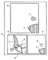
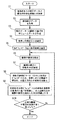
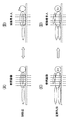
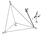
図1から図6は本発明の実施形態1を示したものであり、図1は医用ガイドシステムの構成を示すブロック図、図2は3次元ガイド画像と2次元ガイド画像と超音波画像とが表示装置の表示画面に並べて表示されている様子を示す図、図3は医用ガイドシステムの体位補正部の動作を示すフローチャート、図4は医用ガイドシステムの体位補正部による処理の概要を説明するための図、図5は仰臥位参照ボリュームデータに設定される斜交座標系を示す図、図6は本人仰臥位ボリュームデータに設定される斜交座標系を示す図である。
[Embodiment 1]
1 to 6
本実施形態においては、検出手段により位置および方位を検出する医用器具が超音波内視鏡であるものとして、説明を行う。 In the present embodiment, description will be made assuming that the medical instrument for detecting the position and orientation by the detection means is an ultrasonic endoscope.
本実施形態の医用ガイドシステム1は、超音波内視鏡2と、超音波観測装置3と、位置データ算出装置4と、ガイド画像作成装置5と、キーボード6と、マウス7と、表示装置8と、を備えており、医用器具としての超音波内視鏡2のガイドを行うシステムとなっている。
The
超音波内視鏡2は、先端に配設された超音波振動子21と、この超音波振動子21の後方において該超音波振動子21との位置関係が固定された状態で配設された検出手段たる2個の受信コイル22と、を備えている。これらの内の超音波振動子21は、超音波観測装置3と接続されている。また、2個の受信コイル22は、位置データ算出装置4と接続されている。なお、これら2個の受信コイル22は、それぞれの巻軸方向が、互いに独立した方向となるように構成されている。
The
超音波観測装置3は、上述したように超音波内視鏡2に内蔵されている超音波振動子21と接続されているとともに、さらに、ガイド画像作成装置5と接続されている。
The ultrasonic observation device 3 is connected to the ultrasonic transducer 21 built in the
位置データ算出装置4は、上述したように超音波内視鏡2に内蔵されている受信コイル22と接続されているとともに、さらに、ガイド画像作成装置5と接続されている。この位置データ算出装置4は、送信コイル41と、位置合わせ用受信コイル42と、を備えた検出手段である。送信コイル41は、図示しない複数個の磁場発生用コイルを内蔵して構成されており、後述するように交番磁場を発生するための検出手段である。位置合わせ用受信コイル42は、送信コイル41により発生された交番磁場を受信して、位置合わせを行うための検出手段である。
The position
ガイド画像作成装置5は、制御部51と、保存手段たる画像記憶部52と、補正手段たる体位補正部53と、算出手段たる画像構成部54と、混合部55と、表示回路56と、を備えている。これらの内の、混合部55は超音波観測装置3と、画像構成部54は位置データ算出装置4と、制御部51はキーボード6およびマウス7と、表示回路56は表示装置8と、それぞれ接続されている。また、このガイド画像作成装置5の内部においては、体位補正部53が制御部51および画像記憶部52および画像構成部54と、画像構成部54が制御部51および体位補正部53および混合部55と、混合部55が画像構成部54および表示回路56と接続されている。なお、制御部51には、図示はしないが、画像記憶部52および混合部55および表示回路56も接続されて、制御されるようになっている。
The guide
次に、この医用ガイドシステム1の作用について説明する。
Next, the operation of this
まず、図1を参照して、医用ガイドシステム1の作用の概要について説明する。なお、この図1においては、各矢印線が以下のような信号、データの流れを示すようになっている。すなわち、実線は位置に係る信号・データの流れ、破線は超音波に係る信号・データの流れ、太線は最終的な表示画像に係る信号・データの流れ、一点鎖線はガイド画像に係る信号・データの流れ、曲線はそれ以外の制御に係る信号・データの流れ、をそれぞれ示している。
First, an outline of the operation of the
術者(術者あるいは介助者等を代表して、ここでは単に「術者」という。以下同様。)は、被検者の体腔内に超音波内視鏡2を挿入して、超音波観測装置3を操作することにより超音波スキャンを開始する。
A surgeon (representing a surgeon or an assistant, simply referred to as “surgeon”, hereinafter the same) inserts the
超音波スキャンが開始されると、超音波振動子21は、超音波を被検体へ送信するとともに、該被検体により反射された超音波を受信し、超音波断層面の超音波エコー信号を出力する。 When the ultrasonic scan is started, the ultrasonic transducer 21 transmits the ultrasonic wave to the subject, receives the ultrasonic wave reflected by the subject, and outputs an ultrasonic echo signal of the ultrasonic tomographic plane. To do.
超音波観測装置3は、超音波内視鏡2の超音波振動子21からこの超音波エコー信号を受信して、受信した超音波エコー信号に基づき超音波画像データを作成する。そして、超音波観測装置3は、作成した超音波画像データをガイド画像作成装置5の混合部55へ出力する。
The ultrasonic observation apparatus 3 receives this ultrasonic echo signal from the ultrasonic transducer 21 of the
一方、位置データ算出装置4は、送信コイル41を励磁して、交番磁場を発生させる(より詳しくは、位置データ算出装置4は、送信コイル41に設けられた複数個の磁場発生用コイルに対して、異なる周波数の磁場発生電流を供給して、異なる周波数の磁場を発生させる)。すると、内視鏡に内蔵された受信コイル22が、この送信コイル41からの交番磁場を検出して位置電気信号に変換し、位置データ算出装置4へ出力する。
On the other hand, the position
位置データ算出装置4は、受信コイル22から位置電気信号を受信すると、周波数毎に分離し、分離された各位置電気信号に基づいて、受信コイル22の位置情報と方位情報とを算出する。位置データ算出装置4は、算出した位置情報と方位情報とを、ガイド画像作成装置5の画像構成部54へ出力する。
When receiving the position electrical signal from the receiving coil 22, the position
ガイド画像作成装置5は、以下のような処理を行うようになっている。
The guide
まず、画像記憶部52は、MDCT(MultiDetector Computed Tomography)により取得された被検者本人の複数枚のスライスデータからなるMDCTデータ(本人医用画像データ)を、該MDCTデータを撮影したときの仰臥位や左側臥位等の体位情報とともに予め保存している。さらに、画像記憶部52は、被検者とは別人(他の被検者)を仰臥位や左側臥位や右側臥位や腹臥位などの様々な体位で撮影した参照MDCTデータ(参照用医用画像データ)を、該参照MDCTデータを撮影したときの体位情報とともに予め保存している。ここに、MDCTとは、体軸方向に複数列の検出器列を備えたCTのことであり、体軸方向に配列された各検出器列からのデータを画像計算することにより、1回の走査によって複数断面のスライスデータを得ることができるようになっている。
First, the
術者が、マウス7やキーボード6を操作して、超音波内視鏡2により検査を行うときの被検者の体位を指示すると、この指示に係る信号がガイド画像作成装置5の制御部51に入力される。すると、制御部51は、超音波内視鏡2により検査を行うときの体位情報を体位補正部53へ出力する。
When the surgeon operates the mouse 7 or the
体位補正部53は、制御部51から現在の体位情報が入力されると、画像記憶部52から被検者本人のMDCTデータと画像撮影時の被検者の体位情報とを取得する。そして、体位補正部53は、現在の体位情報と画像撮影時の被検者の体位情報とを比較して、これらが一致している場合には、被検者本人のMDCTデータから特定の臓器や器官を抽出した3次元画像を構築し、構築した3次元画像を画像構成部54へ出力する。一方、体位補正部53は、現在の体位情報と画像撮影時の被検者の体位情報とが一致していない場合には、後で詳細に説明するように、被検者本人のMDCTデータと、このMDCTデータ取得時と同一体位において取得された参照MDCTデータと、に基づいて、臓器や器官毎に、位置や方向の個人差を変換式として算出し、超音波内視鏡2により検査を行うときの被検者の体位と同一体位において取得された参照MDCTデータにこの変換式を適用することにより、該内視鏡検査時の被検者の特定の臓器や器官を抽出した3次元画像を作成する。こうして体位補正部53により作成された3次元画像は、画像構成部54へ出力される。
When the current posture information is input from the
次に、超音波画像データと特定の臓器や器官を抽出した3次元画像との位置合わせの方法について説明する。 Next, a method for aligning ultrasonic image data with a three-dimensional image obtained by extracting a specific organ or organ will be described.
術者が、マウス7やキーボード6を操作して、ガイド画像作成装置5の制御部51に位置合わせの開始を指示すると、制御部51は位置合わせ開始情報を画像構成部54へ出力する。
When the surgeon operates the mouse 7 and the
画像構成部54は、位置合わせ開始情報が入力されると、体位補正部53から入力された特定の臓器や器官を抽出した3次元画像に基づき、この3次元画像を体軸方向と垂直な面でスライスした特徴点指定用2次元画像データを作成する。そして、画像構成部54は、作成した特徴点指定用2次元画像データを混合部55へ出力する。
When the alignment start information is input, the
混合部55は、超音波観測装置3からの超音波画像データと、画像構成部54からの特徴点指定用2次元画像データと、を並べて、表示用のデジタルデータを作成し、表示回路56へ出力する。
The mixing unit 55 arranges the ultrasound image data from the ultrasound observation apparatus 3 and the feature point designating two-dimensional image data from the
表示回路56は、混合部55から入力されたデジタルデータを、表示用の出力信号に変換して、表示装置8へ出力する。
The
表示装置8は、表示回路56からの出力信号に基づいて表示を行うために、この表示装置8には、特徴点指定用2次元画像データと超音波画像とが表示される。
Since the
術者は、特徴点指定用2次元画像データの体軸方向の位置を、マウス7やキーボード6を操作することにより変更しながら、特徴点指定用2次元画像データ上において解剖学的な特徴点を選択する。
The operator changes the position of the feature point specifying 2D image data in the body axis direction by operating the mouse 7 or the
この術者の選択を制御部51を介して受けると、画像構成部54は、特定の臓器や器官を抽出した3次元画像上における特徴点位置を算出する。
When the operator's selection is received via the
その後、術者は、マウス7やキーボード6の操作により選択した解剖学的な特徴点と同一の、被検者上の解剖学的な特徴点に、位置合わせ用受信コイル42または超音波内視鏡2を接触させて、マウス7やキーボード6を操作することにより位置データの取得を指示する。これに応じて制御部51は、位置データ取得命令を画像構成部54へ出力する。画像構成部54は、制御部51から位置データ取得命令を受けると、位置データ算出装置4から入力されている位置データを、特定の臓器や器官を抽出した3次元画像上における特徴点位置と対応付ける。
Thereafter, the surgeon moves the positioning receiving coil 42 or ultrasonic endoscope to the anatomical feature point on the subject that is the same as the anatomical feature point selected by operating the mouse 7 or the
このような特徴点と位置データとの対応付けを、複数の特徴点について行うことにより、超音波画像データと特定の臓器や器官を抽出した3次元画像との位置合わせが完了する。 By associating such feature points with position data for a plurality of feature points, the alignment between the ultrasound image data and the three-dimensional image obtained by extracting a specific organ or organ is completed.
こうして位置合わせが完了した後に、術者が、マウス7やキーボード6を操作して、ガイド画像作成装置5の制御部51に被検者のガイドの開始を指示すると、制御部51は、ガイド開始命令を画像構成部54へ出力する。
After the positioning is completed in this way, when the operator operates the mouse 7 or the
画像構成部54は、制御部51からガイド開始命令を受けると、体位補正部53から入力された特定の臓器や器官を抽出した3次元画像と、位置データ算出装置4から入力された超音波内視鏡2の受信コイル22の位置情報および方位情報と、に基づいて、超音波内視鏡2の超音波画像データ取得位置を算出する。さらに、画像構成部54は、上述した位置合わせ結果に基づいて、特定の臓器や器官を抽出した3次元画像中における超音波画像データ取得位置を算出し、ガイド画像データを作成する。
Upon receiving a guide start command from the
ここに、ガイド画像データは、図2に示すように、3次元ガイド画像8cに係るデータ(3次元ガイド画像データ)と、2次元ガイド画像8dに係るデータ(2次元ガイド画像データ)と、を含んでいる。
Here, as shown in FIG. 2, the guide image data includes data relating to the three-
3次元ガイド画像データは、体位補正部53から入力された特定の臓器や器官(図2に示す例においては、膵臓101、大動脈102、および門脈系の血管103)を抽出した3次元画像中に、超音波画像データ取得位置を表す超音波断層面マーカ104を重畳した画像データである。
The three-dimensional guide image data is obtained by extracting specific organs and organs (in the example shown in FIG. 2,
また、2次元ガイド画像データは、特定の臓器や器官を抽出した3次元画像から、超音波画像データと解剖学的に位置および向きが一致する断面(2次元面)を切り出した画像データである。 The two-dimensional guide image data is image data obtained by cutting out a cross section (two-dimensional plane) whose position and orientation are anatomically coincident with the ultrasonic image data from a three-dimensional image obtained by extracting a specific organ or organ. .
具体例として、図2に示すように、超音波画像データ(表示装置8の表示画面8aにおける超音波画像8b参照)が、十二指腸からみた膵臓頭部(図2中の膵臓101参照)の断面の画像データである場合を挙げる。このときに、画像構成部54は、特定の臓器や器官を抽出した3次元画像に基づいて、該3次元画像中の十二指腸と膵臓頭部とに超音波断層面マーカ104を表示した3次元ガイド画像データを作成する。さらに、画像構成部54は、特定の臓器や器官を抽出した3次元画像に基づいて、該3次元画像から切り出した十二指腸からみた膵臓頭部の断面の2次元ガイド画像データを作成する。そして、画像構成部54は、作成したこれらのガイド画像データを混合部55へ出力する。
As a specific example, as shown in FIG. 2, ultrasound image data (see an
混合部55は、超音波観測装置3からの超音波画像データと画像構成部54からの2種類のガイド画像データとを並べて、表示用のデジタルデータを作成する。
The mixing unit 55 arranges the ultrasonic image data from the ultrasonic observation apparatus 3 and the two types of guide image data from the
表示回路56は、混合部55からのデジタルデータを表示用の出力信号に変換する。
The
表示装置8は、表示回路56からの出力信号に基づいて、超音波画像8bとガイド画像(3次元ガイド画像8cおよび2次元ガイド画像8d)とを並べて、図2に示すように表示画面8aに表示する。
The
こうして、術者は、表示装置8の表示画面8aに表示されているガイド画像8c,8dを見て、現在、超音波画像8bにより観察している位置が、解剖学的に被検者のどの位置であるのかを認識しながら、より正確に診断を行うことができる。
Thus, the surgeon looks at the
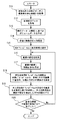
次に、図3のフローチャートを参照して、実際の使用例に沿った体位補正部53の作用を詳細に説明する。
Next, with reference to the flowchart of FIG. 3, the effect | action of the body posture correction |
なお、このフローチャートの説明においては、画像記憶部52に保存されている参照画像としてのMDCTデータに、図4(A)に示すように仰臥位において取得されたものと、図4(C)に示すように左側臥位において取得されたものと、が含まれていることを前提とする。さらに、画像記憶部52に保存されている被検者本人のMDCTデータが図4(B)に示すように仰臥位において取得されたものであり、超音波内視鏡2により検査を行うときの被検者の体位が図4(D)に示すように左側臥位であるものとする。従って、この例においては、体位補正部53により作成される被検者本人の特定の臓器や器官を抽出した3次元画像は、左側臥位の3次元画像となる。
In the description of this flowchart, the MDCT data as the reference image stored in the
以下において詳細に説明する体位補正部53の作用の概略を説明しておくと、次のようになっている。体位補正部53は、まず、図4(A)に示すような仰臥位の参照MDCTデータと、図4(B)に示すような被検者本人の仰臥位MDCTデータとに基づいて、臓器や器官毎に、位置や方向の個人差を変換式として算出する。次に、体位補正部53は、図4(C)に示すような左側臥位参照MDCTデータに、算出した変換式を適用することにより、図4(D)に示すような被検者本人の左側臥位における特定の臓器や器官を抽出した3次元画像を作成する。このようにして、体位補正部53の処理が行われる。
The outline of the operation of the body
体位補正部53は、超音波内視鏡2により検査を行うときの体位情報である「左側臥位」が制御部51から入力されると、画像記憶部52に保存されている仰臥位において取得された被検者本人のMDCTデータ(図4(B)参照)と、このMDCTデータを撮影したときの体位情報である「仰臥位」と、を読み出す(ステップS1)。
The body
次に、体位補正部53は、画像記憶部52に保存されている被検者とは別人を様々な体位で撮影して得られた参照MDCTデータの中から、ステップS1において取得した超音波内視鏡2による検査時の体位情報である「左側臥位」に相当する体位において取得された左側臥位参照MDCTデータ(図4(C)参照)と、被検者本人のMDCTデータを撮影したときの体位情報である「仰臥位」に相当する体位において取得された仰臥位参照MDCTデータ(図4(A)参照)と、を読み出す(ステップS2)。
Next, the body
続いて、体位補正部53は、ステップS1において取得した被検者本人の仰臥位MDCTデータと、ステップS2において読み出した仰臥位参照MDCTデータおよび左側臥位参照MDCTデータと、をそれぞれボリュームデータ化し、本人仰臥位ボリュームデータと仰臥位参照ボリュームデータと左側臥位参照ボリュームデータとを作成する(ステップS3)。
Subsequently, the body
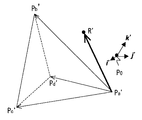
さらに、体位補正部53は、術者による入力により、または自動的な算出により、各ボリュームデータにおける骨格上に4点ずつ特徴点を設定する。本実施形態においては、骨格上に設定する4特徴点が、剣状突起・骨盤右端・骨盤左端・骨盤右端と骨盤左端とを結んだ背骨上の点、であるものとする。なお、各ボリュームデータ上における4特徴点に、次のように符号を付すものとする。まず、仰臥位参照ボリュームデータ上においては、それぞれ、剣状突起P0・骨盤右端P1・骨盤左端P2・骨盤右端と骨盤左端とを結んだ背骨上の点P3、とする(なお、添え字は半角文字で代用することにする。以下同様。)。また、本人仰臥位ボリュームデータ上においては、それぞれ、剣状突起P0'・骨盤右端P1'・骨盤左端P2'・骨盤右端と骨盤左端とを結んだ背骨上の点P3'、とする。さらに、左側臥位参照ボリュームデータ上においては、それぞれ、剣状突起P0"・骨盤右端P1"・骨盤左端P2"・骨盤右端と骨盤左端とを結んだ背骨上の点P3"、とする(ステップS4)。
Further, the body
そして、体位補正部53は、各ボリュームデータ上の骨格4特徴点の内の1点である剣状突起P0,P0',P0"をそれぞれのボリュームデータにおける原点として、この原点から各ボリュームデータにおける残りの3点への次の数式1に示すようなベクトル、すなわち、仰臥位参照ボリュームデータ上のベクトルi,j,k(表記上の理由から、明細書中においては、ベクトルおよび行列を、肉太文字を用いてあるいは文字上に矢印記号を付して表す代わりに、通常の文字を用いることにする。以下同様。)、本人仰臥位ボリュームデータ上のベクトルi’,j’,k’、左側臥位参照ボリュームデータ上のベクトルi”,j”,k”、

により、各ボリュームデータ上に斜交座標を設定する(ステップS5)。そして、以下の計算では、この斜交座標を用いることにする。 Thus, the oblique coordinates are set on each volume data (step S5). The oblique coordinates are used in the following calculation.
続くステップS6〜S9の処理は、ガイド画像中に表示する部位毎(臓器や器官毎)に行うようになっている。従って、複数の部位をガイドに画像中に表示させたい場合には、これらステップS6〜S9の処理を複数回繰り返して行うことになる。 The subsequent steps S6 to S9 are performed for each part (organ or organ) displayed in the guide image. Therefore, when it is desired to display a plurality of parts in the image on the guide, the processes in steps S6 to S9 are repeated a plurality of times.
本実施形態においては、ガイドに使用する部位が、動脈系の主な血管・門脈系の主な血管・膵臓・胆嚢・肝臓・脾臓・腎臓であるものとする。そして、以下においては、説明の便宜上、動脈系の血管についてのみを説明するが、他の臓器や器官についてもステップS6〜S9の処理を同様に繰り返して行えばよい。 In the present embodiment, the parts used for the guide are the main blood vessels of the arterial system, the main blood vessels of the portal vein system, the pancreas, the gallbladder, the liver, the spleen, and the kidney. In the following, for convenience of explanation, only the arterial blood vessels will be described, but the processing of steps S6 to S9 may be similarly repeated for other organs and organs.
すなわち、体位補正部53は、仰臥位参照ボリュームデータと本人仰臥位ボリュームデータと左側臥位参照ボリュームデータとのそれぞれについて、動脈系の主な血管を抽出する(ステップS6)。
That is, the body
次に、体位補正部53は、ステップS6により抽出した部位上に、血管の分岐点などの特徴点を4点、術者による指定により、または自動的な算出により指定する(ステップS7)。ここに、仰臥位参照ボリュームデータ上において指定された特徴点をそれぞれPa、Pb、Pc、Pdとし、本人仰臥位ボリュームデータ上において指定された特徴点をそれぞれPa'、Pb'、Pc'、Pd'とする。これらの特徴点は、PaとPa'、PbとPb'、PcとPc'、PdとPd'がそれぞれ解剖学的に同じ位置を表す特徴点である。
Next, the body
これらの特徴点の斜交座標上における位置は、ステップS5により各ボリュームデータ上に設定した斜交座標系P0-ijkと斜交座標系P0'-i'j'k'とにおいて、それぞれ次の数式2および数式3に示すように表記することができる。
ところで、人体の骨格に対する各臓器の配置や大きさは、人によって異なると考えられる。そのために、ステップS7において指定した4点に基づいて、仰臥位参照ボリュームデータ上の動脈系の主な血管の位置や方向を本人仰臥位ボリュームデータ上の動脈系の主な血管の位置や方向に変換する変換式を算出することにより、臓器位置の個人差を定式化する(ステップS8)。 By the way, it is considered that the arrangement and size of each organ with respect to the skeleton of the human body vary from person to person. For this purpose, based on the four points designated in step S7, the positions and directions of the main blood vessels of the arterial system on the supine position reference volume data are changed to the positions and directions of the main blood vessels of the arterial system on the person's supine position volume data. By calculating a conversion formula to be converted, individual differences in organ positions are formulated (step S8).
このステップS8における定式化の手段について、図5および図6を参照しながら以下に説明する。 The formulation means in step S8 will be described below with reference to FIGS.
仰臥位参照ボリュームデータ上の動脈系の主な血管の任意の点Rが図5に示す三角錐PaPbPcPdに対して特定の位置にあるとすると、本人仰臥位ボリュームデータ上の図6に示す三角錐Pa'Pb'Pc'Pd'に対して同等の位置にある点R'は動脈系の主な血管上の点Rと同一の点に相当すると仮定することができる。この仮定の下では、適当な実数a,b,cを用いた次の数式4および数式5が成り立つ。
ここで、点Rの位置ベクトルPaRの斜交座標軸i,j,kにおける各方向成分をxR,yR,zRと定義すると、次の数式6が成り立つ。
同様に、点R'の位置ベクトルPa'R'の斜交座標軸i’,j’,k’における各方向成分をxR',yR',zR'と定義すると、次の数式7が成り立つ。
以下では、上述した各式に基づいて、仰臥位参照ボリュームデータ上にある任意点Rから、本人仰臥位ボリュームデータ上の対応点R'の位置ベクトルP0'R'と、この対応点R'の斜交座標の各方向成分xR',yR',zR'と、を求める。 In the following, based on the above-described equations, from an arbitrary point R on the supine position volume data, a position vector P0'R 'of the corresponding point R' on the person's supine position volume data and the corresponding point R ' Each direction component xR ′, yR ′, zR ′ of the oblique coordinates is obtained.
まず、数式4を原点P0からの位置ベクトルとして表すことにより、次の数式8が得られる。
この数式8を、数式2および数式6を用いて成分表記することにより、次の数式9が得られる。
ここで、以降の式を簡単に表現するために、次の数式10に示すような3×3行列Qを定義しておく。
この数式10を数式9に代入することにより、次の数式11が得られる。
従って、数式11の両辺に行列Qの逆行列を左から演算することにより、次の数式12が得られる。
一方、数式5を原点P0'からの位置ベクトルとして表すことにより、数式4から数式8を得たのと同様に、次の数式13が得られる。
さらに、この数式13を、数式3および数式7を用いて成分表記することにより、数式2および数式6を数式8に適用して数式9を導いたのと同様にして、次の数式14が得られる。
ここでも、以降の式を簡単に表現するために、次の数式15に示すような3×3行列Q’を定義しておく。
この数式15を数式14に代入することにより、次の数式16が得られる。
この数式16の右辺のa,b,cは、上述した数式12により定められるために、数式12を数式16へ代入することにより、次の数式17が得られる。
従って、次の数式18が得られる。
こうして、数式7と数式18とにより、仰臥位参照ボリュームデータ上にある任意点Rから、本人仰臥位ボリュームデータ上の対応点R'の位置ベクトルP0'R'と、この対応点R'の斜交座標の各方向成分xR',yR',zR'と、が求められた。
Thus, according to
これにより、仰臥位参照ボリュームデータ上の動脈系の主な血管と、本人仰臥位ボリュームデータ上の動脈系の主な血管と、の関係が定式化された。 As a result, the relationship between the main blood vessels of the arterial system on the supine position volume data and the main blood vessels of the arterial system on the person's supine position volume data was formulated.
上述したようなステップS8の処理が終了したら、次に、ステップS9の処理を行う。すなわち、上述したステップS8において算出した仰臥位参照ボリュームデータ上の動脈系の主な血管と本人仰臥位ボリュームデータ上の動脈系の主な血管との関係式(臓器位置の個人差)に基づいて、左側臥位参照ボリュームデータ上の動脈系の主な血管を被検者本人が左側臥位になった場合の動脈系の主な血管の推定位置に補正することにより、本人左側臥位ボリュームデータを作成する(ステップS9)。 When the process of step S8 as described above is completed, the process of step S9 is performed next. That is, based on the relational expression (individual difference in organ position) between the main blood vessels of the arterial system on the supine position reference volume data calculated in step S8 and the main blood vessels of the arterial system on the person's supine position volume data. By correcting the main blood vessels of the arterial system on the left supine reference volume data to the estimated position of the main blood vessels of the arterial system when the subject is in the left supine position, the left supine position volume data Is created (step S9).
このステップS9における処理の詳細について、以下に説明する。 Details of the processing in step S9 will be described below.
まず、ステップS6において抽出した左側臥位参照ボリュームデータ上の動脈系の主な血管上の画素R”について、その位置を、ステップS5において算出した左側臥位参照ボリュームデータ上の斜交座標系P0"-i"j"k"を用いて、次の数式19に示すように表す。
また、この画素R”を被検者本人の左側臥位における位置に補正した位置R'''を、斜交座標系P0"-i"j"k"を用いて次の数式20に示すように表す。
そして、上述した数式18を、次の数式21に示すように置き換える。
次に、数式21にxR",yR",zR"を代入することにより、画素R”の被検者本人の左側臥位における位置xR''',yR''',zR'''を算出することができる。 Next, by substituting xR ″, yR ″, zR ″ into Equation 21, the positions xR ′ ″, yR ′ ″, zR ′ ″ of the subject R in the left lateral position of the subject himself / herself are calculated. can do.
こうして算出した位置xR''',yR''',zR'''に、R”の画素値を配置する。 The pixel values of R ″ are arranged at the positions xR ′ ″, yR ′ ″, zR ′ ″ calculated in this way.
このような処理を動脈系の主な血管の画像を構成する全ての画素について行うことにより、動脈系の主な血管についての被検者本人の左側臥位3次元画像が完成する。 By performing such processing for all the pixels constituting the main blood vessel image of the arterial system, a left-sided three-dimensional image of the subject himself about the main blood vessel of the arterial system is completed.
その後、ガイド画像中に表示させたい全ての部位について、ステップS6〜S9の処理が完了したか否かを判定する(ステップS10)。上述したように、本実施形態においては、ガイドに使用する部位を、動脈系の主な血管・門脈系の主な血管・膵臓・胆嚢・肝臓・脾臓・腎臓としている。従って、このステップS10において、全ての部位についての処理がまだ完了していないと判定された場合には、ステップS6へ戻って、上記7種の臓器もしくは器官の内の未処理の部位について部位を変更しながら、上述したようなステップS6〜S9の処理を繰り返して行う。 Thereafter, it is determined whether or not the processing in steps S6 to S9 has been completed for all the parts to be displayed in the guide image (step S10). As described above, in this embodiment, the sites used for the guide are the main blood vessels of the arterial system, the main blood vessels of the portal vein system, the pancreas, the gallbladder, the liver, the spleen, and the kidney. Accordingly, in this step S10, when it is determined that the processing for all the parts has not been completed yet, the process returns to step S6, and the parts for the seven types of organs or unprocessed parts of the organs are selected. While changing, the processes in steps S6 to S9 as described above are repeated.
こうして、ステップS10において、全ての部位についての処理が完了したと判定された場合には、被検者本人の左側臥位の特定の臓器や器官を抽出した3次元画像が完成したことになり、この処理を終了する。 Thus, when it is determined in step S10 that the processing for all the parts has been completed, a three-dimensional image in which a specific organ or organ in the left lateral position of the subject person is extracted is completed, This process ends.
このような実施形態1によれば、超音波内視鏡2により検査を行うときの被検者の体位がMDCTを撮像したときの被検者の体位と異なっていた場合でも、ガイド画像の臓器や器官の位置と方向とを被検者の体位に合わせて変更することができるために、ガイド画像上の超音波走査面と周辺臓器や周辺器官との位置関係が、実際の超音波内視鏡2と臓器や器官との位置関係と精度良く一致する。このことは、病変部等の関心領域へのアプローチを早くすることにつながり、検査時間の短縮に寄与することができる。
According to the first embodiment, the organ of the guide image is used even when the posture of the subject when the examination is performed by the
また、仰臥位において撮影したMDCTの臓器や器官の位置と方向とを、左側臥位のものに補正することができるために、超音波内視鏡2による検査時のガイドを行うために左側臥位でMDCTを撮像する必要が無くなる。つまり、通常に撮影された仰臥位のCTを使用して、超音波内視鏡2による検査時のガイド画像を作成することができるために、被検者および術者の事前準備に要する負担を軽減することができる。
In addition, since the MDCT organs and organ positions and directions taken in the supine position can be corrected to those in the left-sided position, the left-sided eyelid is used to guide the examination with the
さらに、超音波内視鏡2による検査においては、空気中では超音波が減衰してしまうために、管腔内に水をためて、ためた水の中に超音波振動子21を入れて超音波画像を取得することがある。このとき、管腔内に水をため易いように、被検者の体位を検査中に変更することがある。このような場合にも、体位情報を入力することにより、検査中にガイド画像の臓器位置を体位に合わせて補正することが可能となる利点がある。
Further, in the examination using the
そして、臓器や器官を部位毎に分けて、それぞれの部位毎に体位に基づく補正を行うようにしたために、臓器や器官毎の配置や大きさに個人差がある場合にも、臓器や器官毎に最適な補正が可能となる。こうして、ガイド画像上の超音波走査面と周辺臓器や周辺器官との位置関係を、実際の超音波内視鏡2と臓器や器官との位置関係と、精度良く一致させることができる。
Since the organs and organs are divided into parts and correction based on the body position is performed for each part, even when there are individual differences in the arrangement and size of each organ and organ, It is possible to make an optimal correction for the above. In this way, the positional relationship between the ultrasonic scanning plane on the guide image and the peripheral organs and peripheral organs can be matched with the positional relationship between the actual
加えて、被検者の体位が変化したときに、体の下側に位置するなどの理由により形状が変形する臓器や器官の場合であっても、超音波内視鏡2による検査時の体位と同じ体位で撮影された別人の参照CTの各臓器や器官に基づいて、個人差を加味して臓器や器官の大きさと配置とを補正するようにしたために、ガイド画像上の臓器や器官にその体位における臓器や器官の形状を反映させて再現することができる。これにより、実際の超音波画像上の臓器や器官の形状と、ガイド画像上の臓器や器官の形状と、が精度良く一致する。
In addition, when the posture of the subject is changed, the posture at the time of examination by the
また、超音波画像と解剖学的な3次元画像との位置合わせを行う際にも、体位補正を行った解剖学的な3次元画像から2次元断層画像データを作成して、作成した2次元断層画像データ上において特徴点を指定することができる。このために、ガイド画像上の超音波走査面と周辺臓器や周辺器官との位置関係が、実際の超音波内視鏡2と臓器や器官との位置関係と、精度良く一致する。
Also, when aligning an ultrasound image and an anatomical three-dimensional image, two-dimensional tomographic image data is created from the anatomical three-dimensional image subjected to body position correction, and the created two-dimensional Feature points can be specified on tomographic image data. For this reason, the positional relationship between the ultrasonic scanning plane on the guide image and the peripheral organs and peripheral organs coincides with the positional relationship between the actual
なお、上述においては、画像記憶部52に記録される情報(本人医用画像データ)の一つとして、被検者本人のMDCTを挙げているが、これに限るものではない。すなわち、被検者本人の解剖学的な画像情報であって、該画像情報に基づいてボリュームデータを作成することが可能であるような情報であれば、MRI画像や超音波画像であっても良い。
In the above description, the MDCT of the subject person is cited as one of the information (personal medical image data) recorded in the
同様に、画像記憶部52に記録される情報(参照用医用画像データ)の一つとして、被検者とは別人を様々な体位で撮影した参照MDCTを挙げているが、これに限るものでもない。すなわち、ボリュームデータを作成することが可能であるような情報であれば、MRI画像や超音波画像であっても良いし、複数人(他の被検者群)のデータの平均値から作成した臓器モデルのようなものであっても構わない。
Similarly, as one of the information (reference medical image data) recorded in the
また、上述では、ガイドする対象となる医用器具を超音波内視鏡2としているが、これに限るものではない。医用器具は、例えば、腹腔鏡やこの腹腔鏡に用いる処置具であっても良く、あるいは、内視鏡の挿入部内に管路として設けられている処置具チャンネルに挿入する処置具であっても構わない。
In the above description, the medical instrument to be guided is the
さらに、上述では、各臓器や器官の位置を補正する際に、2種類のボリュームデータにおいて、対象となる臓器上に設定した4点から求めた斜交座標を用いて、変換式を算出しているが、手段はこれに限るものではない。例えば、2種類のボリュームデータにおいて、臓器上に指定した2組の複数点集合に基づき、擬似逆行列を用いて算出するようにしても良い。 Furthermore, in the above description, when correcting the position of each organ or organ, the conversion formula is calculated using the oblique coordinates obtained from the four points set on the target organ in the two types of volume data. However, the means is not limited to this. For example, two types of volume data may be calculated using a pseudo inverse matrix based on two sets of multiple points designated on an organ.
[実施形態2]
図7および図8は本発明の実施形態2を示したものであり、図7は医用ガイドシステムの体位補正部の動作を示すフローチャート、図8は医用ガイドシステムの体位補正部による処理の概要を説明するための図である。
[Embodiment 2]
FIGS. 7 and 8
この実施形態2において、上述の実施形態1と同様である部分については同一の符号を付して説明を省略し、主として異なる点についてのみ説明する。 In the second embodiment, parts that are the same as those in the first embodiment are given the same reference numerals and description thereof is omitted, and only differences are mainly described.
まず、本発明の医用ガイドシステムの構成は、上述した実施形態1の図1に示したものと同様である。 First, the configuration of the medical guide system of the present invention is the same as that shown in FIG.
これに対して、本実施形態の医用ガイドシステムは、ガイド画像作成装置5の体位補正部53の作用が、上述した実施形態1とは異なるものとなっている。
On the other hand, in the medical guide system of the present embodiment, the action of the body
以下では、図7のフローチャートを参照して、実際の使用例に沿った体位補正部53の作用の詳細を説明する。
Below, with reference to the flowchart of FIG. 7, the detail of an effect | action of the body posture correction |
なお、このフローチャートの説明においては、上述した実施形態1と同様に、画像記憶部52に保存されている参照画像としてのMDCTデータに、図8(A)に示すように仰臥位において被検者とは別人(他の被検者)に対して取得されたものと、図8(C)に示すように左側臥位において該被検者とは別人に対して取得されたものと、が含まれていることを前提とする。さらに、画像記憶部52に保存されている被検者本人のMDCTデータが図8(B)に示すように仰臥位において取得されたものであり、超音波内視鏡2により検査を行うときの被検者の体位が図8(D)に示すように左側臥位であるものとする。従って、本実施形態においても、被検者本人の左側臥位の特定の臓器や器官を抽出した3次元画像を作成する場合を例に説明する。
In the description of this flowchart, as in the first embodiment described above, the MDCT data as the reference image stored in the
以下において詳細に説明する体位補正部53の作用の概略を説明しておくと、次のようになっている。体位補正部53は、まず、図8(A)に示すような仰臥位の参照MDCTデータと、図8(C)に示すような左側臥位の参照MDCTデータとに基づいて、臓器や器官毎の体位差による変位を変換式として算出する。次に、体位補正部53は、図8(B)に示すような被検者本人の仰臥位MDCTデータに、算出した変換式を適用することにより、図8(D)に示すような被検者本人の左側臥位における特定の臓器や器官を抽出した3次元画像を作成する。このようにして、体位補正部53の処理が行われる。
The outline of the operation of the body
図7に示す処理を開始すると、体位補正部53は、ステップS11〜S16に示すような処理を行うが、これらの処理は、上述した実施形態1のステップS1〜S6に示した処理とそれぞれ同様であるために、説明を省略する。
When the process shown in FIG. 7 is started, the body
なお、ステップS16および次に説明するステップS17〜S19の処理は、ガイドに使用する部位毎(臓器や器官毎)に行うようになっている。従って、複数の部位をガイドに使用したい場合には、これらステップS16〜S19の処理を複数回繰り返して行うことになる。 In addition, the process of step S16 and step S17-S19 demonstrated below is performed for every site | part (for every organ and organ) used for a guide. Therefore, when it is desired to use a plurality of parts for the guide, the processes in steps S16 to S19 are repeated a plurality of times.
本実施形態においては、ガイドに使用する部位が、動脈系の主な血管・門脈系の主な血管・膵臓・胆嚢・肝臓・脾臓・腎臓であるものとする。そして、以下においては、説明の便宜上、動脈系の血管についてのみを説明するが、他の臓器や器官についてもステップS16〜S19の処理を同様に繰り返して行えばよい。 In the present embodiment, the parts used for the guide are the main blood vessels of the arterial system, the main blood vessels of the portal vein system, the pancreas, the gallbladder, the liver, the spleen, and the kidney. In the following, for convenience of explanation, only the arterial blood vessels will be described, but the processing of steps S16 to S19 may be similarly repeated for other organs and organs.
すなわち、体位補正部53は、ステップS16の処理により抽出された部位上に、術者による入力により、または自動的な算出により、特徴点を4点ずつ指定する(ステップS17)。ここに、仰臥位参照ボリュームデータ上において指定された特徴点をそれぞれPa、Pb、Pc、Pdとし、左側臥位参照ボリュームデータ上において指定された特徴点をそれぞれPa"、Pb"、Pc"、Pd"とする。これらの特徴点は、PaとPa"、PbとPb"、PcとPc"、PdとPd"がそれぞれ解剖学的に同じ位置を表す特徴点である。
In other words, the body
これらの特徴点の斜交座標上における位置は、ステップS15により各ボリュームデータ上に設定した斜交座標系P0-ijkと斜交座標系P0"-i"j"k"とにおいて、それぞれ次の数式22および数式23に示すように表記することができる。
ところで、人体の骨格に対する各臓器の配置は、体位によって各臓器への重力の方向が変わることにより変化すると考えられる。そのために、ステップS17において指定した4点に基づいて、仰臥位参照ボリュームデータ上の動脈系の主な血管の位置を左側臥位参照ボリュームデータ上の動脈系の主な血管の位置に変換する変換式を算出することにより、体位による臓器位置の違いを定式化する(ステップS18)。 By the way, the arrangement of each organ with respect to the skeleton of the human body is considered to change as the direction of gravity on each organ changes depending on the body position. For this purpose, based on the four points designated in step S17, a conversion for converting the position of the main blood vessels of the arterial system on the supine position reference volume data into the position of the main blood vessels of the arterial system on the left side position reference volume data. By calculating the formula, the difference in organ position depending on the body position is formulated (step S18).
このステップS18における定式化の手段について、以下に説明する。 The formulation means in step S18 will be described below.
仰臥位参照ボリュームデータ上の動脈系の主な血管の任意の点Rが三角錐PaPbPcPdに対して特定の位置にあるとすると、左側臥位参照ボリュームデータ上の三角錐Pa"Pb"Pc"Pd"に対して同等の位置にある点R”は動脈系の主な血管上の点Rと同一の点に相当すると仮定することができる。この仮定の下では、適当な実数a,b,cを用いた次の数式24および数式25が成り立つ。
ここで、点Rの位置ベクトルPaRの斜交座標軸i,j,kにおける各方向成分をxR,yR,zRと定義すると、次の数式26が成り立つ。
同様に、点R”の位置ベクトルPa"R”の斜交座標軸i”,j”,k”における各方向成分をxR",yR",zR"と定義すると、次の数式27が成り立つ。
以下では、上述した各式に基づいて、仰臥位参照ボリュームデータ上にある任意点Rから、左側臥位参照ボリュームデータ上の対応点R”の位置ベクトルP0"R”と、この対応点R”の斜交座標の各方向成分xR",yR",zR"と、を求める。 In the following, based on the above-described equations, the position vector P0 "R" of the corresponding point R "on the left-side prone position reference volume data from the arbitrary point R on the supine position reference volume data and the corresponding point R" Each direction component xR ", yR", zR "of the oblique coordinates is obtained.
まず、数式24を原点P0からの位置ベクトルとして表すことにより、次の数式28が得られる。
この数式28を、数式22および数式26を用いて成分表記することにより、次の数式29が得られる。
ここで、以降の式を簡単に表現するために、次の数式30に示すような3×3行列Qを定義しておく。
この数式30を数式29に代入することにより、次の数式31が得られる。
従って、数式31の両辺に行列Qの逆行列を左から演算することにより、次の数式32が得られる。
一方、数式25を原点P0"からの位置ベクトルとして表すことにより、数式24から数式28を得たのと同様に、次の数式33が得られる。
さらに、この数式33を、数式23および数式27を用いて成分表記することにより、数式22および数式26を数式28に適用して数式29を導いたのと同様にして、次の数式34が得られる。
ここでも、以降の式を簡単に表現するために、次の数式35に示すような3×3行列Q”を定義しておく。
この数式35を数式34に代入することにより、次の数式36が得られる。
この数式36の右辺のa,b,cは、上述した数式32により定められるために、数式32を数式36へ代入することにより、次の数式37が得られる。
従って、次の数式38が得られる。
こうして、数式27と数式38とにより、仰臥位参照ボリュームデータ上にある任意点Rから、左側臥位参照ボリュームデータ上の対応点R”の位置ベクトルP0"R”と、この対応点R”の斜交座標の各方向成分xR",yR",zR"と、が求められた。 Thus, according to Equations 27 and 38, the position vector P0 "R" of the corresponding point R "on the left-side supine reference volume data from the arbitrary point R on the supine reference volume data and the corresponding point R" The directional components xR ", yR", zR "of the oblique coordinates were obtained.
これにより、仰臥位参照ボリュームデータ上の動脈系の主な血管と、左側臥位参照ボリュームデータ上の動脈系の主な血管と、の関係が定式化された。 As a result, the relationship between the main blood vessels of the arterial system on the supine position reference volume data and the main blood vessels of the arterial system on the left side supine reference volume data was formulated.
上述したようなステップS18の処理が終了したら、次に、ステップS19の処理を行う。すなわち、上述したステップS18において算出した仰臥位参照ボリュームデータ上の動脈系の主な血管と左側臥位参照ボリュームデータ上の動脈系の主な血管との関係式(体位による臓器位置の差)に基づいて、本人仰臥位ボリュームデータ上の動脈系の主な血管を被検者本人が左側臥位になった場合の動脈系の主な血管位置に補正することにより、本人左側臥位ボリュームデータを作成する(ステップS19)。 When the process of step S18 as described above is completed, the process of step S19 is performed next. That is, the relational expression between the main blood vessels of the arterial system on the supine reference volume data calculated in step S18 and the main blood vessels of the arterial system on the left supine reference volume data (the difference in organ position depending on the body position). Based on this, by correcting the main blood vessels of the arterial system on the person's supine position volume data to the main blood vessel position of the arterial system when the subject is in the left supine position, Create (step S19).
このステップS19における処理の詳細について、以下に説明する。 Details of the processing in step S19 will be described below.
まず、ステップS16において抽出した本人仰臥位ボリュームデータ上の動脈系の主な血管上の画素R’について、その位置を、ステップS15において算出した本人仰臥位ボリュームデータ上の斜交座標系P0'-i'j'k'を用いて、次の数式39に示すように表す。
![]()
![]()
また、この画素R’を被検者本人の左側臥位における位置に補正した位置R'''を、斜交座標系P0'-i'j'k'を用いて次の数式40に示すように表す。
![]()
![]()
そして、上述した数式38を、次の数式41に示すように置き換える。
次に、数式41にxR',yR',zR'を代入することにより、画素R’の被検者本人の左側臥位における位置xR''',yR''',zR'''を算出することができる。
Next, by substituting xR ′, yR ′, and zR ′ into
こうして算出した位置xR''',yR''',zR'''に、R”の画素値を配置する。 The pixel values of R ″ are arranged at the positions xR ′ ″, yR ′ ″, zR ′ ″ calculated in this way.
このような処理を動脈系の主な血管の画像を構成する全ての画素について行うことにより、動脈系の主な血管についての被検者本人の左側臥位3次元画像が完成する。 By performing such processing for all the pixels constituting the main blood vessel image of the arterial system, a left-sided three-dimensional image of the subject himself about the main blood vessel of the arterial system is completed.
その後、ガイド画像中に表示させたい全ての部位について、ステップS16〜S19の処理が完了したか否かを判定する(ステップS20)。上述したように、本実施形態においては、ガイドに使用する部位を、動脈系の主な血管・門脈系の主な血管・膵臓・胆嚢・肝臓・脾臓・腎臓としている。従って、このステップS20において、全ての部位についての処理がまだ完了していないと判定された場合には、ステップS16へ戻って、上記7種の臓器もしくは器官の内の未処理の部位について部位を変更しながら、上述したようなステップS16〜S19の処理を繰り返して行う。 Thereafter, it is determined whether or not the processing in steps S16 to S19 has been completed for all the parts to be displayed in the guide image (step S20). As described above, in this embodiment, the sites used for the guide are the main blood vessels of the arterial system, the main blood vessels of the portal vein system, the pancreas, the gallbladder, the liver, the spleen, and the kidney. Therefore, if it is determined in step S20 that the processing for all the parts has not been completed, the process returns to step S16, and the parts for the unprocessed parts of the seven types of organs or organs are selected. While changing, the processes in steps S16 to S19 as described above are repeated.
こうして、ステップS20において、全ての部位についての処理が完了したと判定された場合には、被検者本人の左側臥位の特定の臓器や器官を抽出した3次元画像が完成したことになり、この処理を終了する。 Thus, when it is determined in step S20 that the processing for all the parts has been completed, a three-dimensional image in which a specific organ or organ in the left lateral position of the subject person is extracted is completed, This process ends.
このような実施形態2によれば、超音波内視鏡2により検査を行うときの被検者の体位がMDCTを撮像したときの被検者の体位と異なっていた場合でも、ガイド画像の臓器や器官の位置を被検者の体位に合わせて変更することができるために、ガイド画像上の超音波走査面と周辺臓器や周辺器官との位置関係が、実際の超音波内視鏡2と臓器や器官との位置関係と精度良く一致する。このことは、病変部等の関心領域へのアプローチを早くすることにつながり、検査時間の短縮に寄与することができる。
According to the second embodiment, even when the body position of the subject when the examination is performed by the
また、仰臥位において撮影したMDCTの臓器や器官の位置を、左側臥位のものに補正することができるために、超音波内視鏡2による検査時のガイドを行うために左側臥位でMDCTを撮像する必要が無くなる。つまり、通常に撮影された仰臥位のCTを使用して、超音波内視鏡2による検査時のガイドを行うことができるために、被検者および術者の事前準備に要する負担を軽減することができる。
In addition, since the MDCT organs and organ positions taken in the supine position can be corrected to those in the left-sided position, the MDCT can be used in the left-sided position in order to perform a guide during the examination by the
さらに、超音波内視鏡2による検査においては、空気中では超音波が減衰してしまうために、管腔内に水をためて、ためた水の中に超音波振動子21を入れて超音波画像を取得することがある、このとき、管腔内に水をため易いように、被検者の体位を検査中に変更することがある。このような場合にも、体位情報を入力することにより、検査中にガイド画像の臓器位置を体位に合わせて補正することが可能となる利点がある。
Further, in the examination using the
そして、臓器や器官を部位毎に分けて、それぞれの部位毎に体位に基づく補正を行うようにしたために、臓器や器官毎の配置や大きさに個人差がある場合にも、臓器や器官毎に最適な補正が可能となる。こうして、ガイド画像上の超音波走査面と周辺臓器や周辺器官との位置関係を、実際の超音波内視鏡2と臓器や器官との位置関係と、精度良く一致させることができる。
Since the organs and organs are divided into parts and correction based on the body position is performed for each part, even when there are individual differences in the arrangement and size of each organ and organ, It is possible to make an optimal correction for the above. In this way, the positional relationship between the ultrasonic scanning plane on the guide image and the peripheral organs and peripheral organs can be matched with the positional relationship between the actual
加えて、超音波内視鏡2による検査を受診する被検者本人の仰臥位CTにおける各画素に変換式を適用することにより、各臓器や器官の配置の体位変化による重力の影響を反映させているために、人によって形状に大きな違いがある臓器や器官あるいは病変部であっても、ガイド画像上の臓器や器官に被検者本人特有の形状や病変部を再現することができる。このために、実際の超音波画像上の臓器や器官の形状とガイド画像上の臓器や器官の形状とが精度良く一致する。
In addition, by applying a conversion formula to each pixel in the supine position CT of the subject himself / herself who undergoes the examination by the
また、超音波内視鏡2による検査を受診する被検者本人の仰臥位CTにおける各画素値をそのままガイド画像上に表示するようにしているために、被検者本人の病変部を超音波画像と比較することができる。このために、実際の超音波画像上の臓器や器官の形状とガイド画像上の臓器や器官の形状とが精度良く一致する。
In addition, since each pixel value in the supine position CT of the subject who undergoes the examination by the
また、超音波画像と解剖学的な3次元画像との位置合わせを行う際にも、体位補正を行った解剖学的な3次元画像から2次元断層画像データを作成して、作成した2次元断層画像データ上において特徴点を指定することができる。このために、ガイド画像上の超音波走査面と周辺臓器や周辺器官との位置関係が、実際の超音波内視鏡2と臓器や器官との位置関係と、精度良く一致する。
Also, when aligning an ultrasound image and an anatomical three-dimensional image, two-dimensional tomographic image data is created from the anatomical three-dimensional image subjected to body position correction, and the created two-dimensional Feature points can be specified on tomographic image data. For this reason, the positional relationship between the ultrasonic scanning plane on the guide image and the peripheral organs and peripheral organs coincides with the positional relationship between the actual
なお、被検者本人のMDCTに代えて、被検者本人のMRI画像や超音波画像を本人医用画像データとして用いても良いことは、上述した実施形態1と同様である。 It is to be noted that the subject's own MRI image or ultrasonic image may be used as the subject's medical image data instead of the subject's MDCT, as in the first embodiment described above.
同様に、参照MDCTに代えて、被検者とは別人のMRI画像や超音波画像、あるいは複数人(他の被検者群)のデータの平均値から作成した臓器モデルを参照用医用画像データとして用いても構わないことも、上述した実施形態1と同様である。 Similarly, instead of the reference MDCT, an MRI image or ultrasound image of a person different from the subject, or an organ model created from an average value of data of a plurality of people (other subject groups) is used as reference medical image data. It may be used as is the same as in the first embodiment described above.
また、ガイドする対象となる医用器具が、腹腔鏡や処置具であっても構わないことも、上述した実施形態1と同様である。 In addition, the medical instrument to be guided may be a laparoscope or a treatment tool, as in the first embodiment.
さらに、各臓器や器官の位置を補正するための変換式の算出を、例えば、2種類のボリュームデータにおいて、臓器上に指定した2組の複数点集合に基づき、擬似逆行列を用いて行うようにしても良いことも、上述した実施形態1と同様である。 Further, the calculation of the conversion formula for correcting each organ and the position of the organ is performed using, for example, a pseudo inverse matrix based on two sets of plural points designated on the organ in two types of volume data. This may be the same as in the first embodiment.
加えて、本実施形態においては、ガイド画像作成装置5の画像記憶部52に様々な体位における参照MDCTデータを保存しておき、このMDCTデータに基づき体位補正部53が、各臓器や器官毎に、体位による変位を与える変換式を算出するように構成した。しかし、本実施形態は、このような構成に限るものではない。例えば、各体位におけるMDCTデータに基づき作成した各臓器や器官毎の体位に応じた変換式を予め算出しておき、算出した変換式を体位補正部53に保持しておくようにしても良い。このような構成を採用すると、体位補正部53により参照MDCTデータの解析を行うことが不要となるために、体位補正処理をより高速に行うことが可能となる。
In addition, in the present embodiment, reference MDCT data in various positions is stored in the
なお、本発明は上述した実施形態に限定されるものではなく、発明の主旨を逸脱しない範囲内において種々の変形や応用が可能であることは勿論である。 It should be noted that the present invention is not limited to the above-described embodiments, and various modifications and applications can be made without departing from the spirit of the invention.
[付記]
以上詳述したような本発明の上記実施形態によれば、以下のごとき構成を得ることができる。
[Appendix]
According to the above-described embodiment of the present invention described in detail above, the following configuration can be obtained.
(1) 医用器具の位置および方位を検出する検出手段と、
前記医用器具を使用する以前に取得された医用画像データを保存する保存手段と、
前記医用画像データ中における臓器と器官との少なくとも一方の、位置と方向との少なくとも一方を、被検者の体位に合わせて補正する補正手段と、
前記検出手段により検出した前記医用器具の位置および方位に基づいて、前記補正手段が補正した前記医用画像データにおける前記医用器具の位置を算出する算出手段と、
を具備したことを特徴とする医用ガイドシステム。
(1) detection means for detecting the position and orientation of the medical instrument;
Storage means for storing medical image data acquired before using the medical instrument;
Correction means for correcting at least one of the position and direction of at least one of the organs and organs in the medical image data in accordance with the posture of the subject;
Calculation means for calculating the position of the medical instrument in the medical image data corrected by the correction means based on the position and orientation of the medical instrument detected by the detection means;
A medical guide system comprising:
(2) 前記保存手段は、前記医用画像データとして、前記医用器具を使用する以前に取得された被検者本人の本人医用画像データを保存するものであり、
前記補正手段は、他の被検者から取得した、臓器と器官との少なくとも一方の、位置と方向との少なくとも一方の、体位の違いに伴う変位を保持しており、前記変位に基づいて、前記本人医用画像データ中における臓器と器官との少なくとも一方の、位置と方向との少なくとも一方を、体位に合わせて補正するものであることを特徴とする付記(1)に記載の医用ガイドシステム。
(2) The storage means stores the medical image data of the subject himself / herself acquired before using the medical instrument as the medical image data,
The correction means is obtained from another subject, at least one of the organ and the organ, at least one of the position and the direction, holding a displacement due to the difference in body position, based on the displacement, The medical guide system according to appendix (1), wherein at least one of the position and the direction of at least one of the organs in the personal medical image data is corrected according to the body position.
(3) 前記保存手段は、前記医用画像データとして、前記医用器具を使用する以前に取得された被検者本人の本人医用画像データと、該本人医用画像データを取得したときの被検者と同一体位の他の被検者から前記医用器具を使用する以前に取得された第1の参照用医用画像データと、該本人医用画像データを取得したときの被検者とは異なる体位の前記他の被検者から前記医用器具を使用する以前に取得された第2の参照用医用画像データと、を保存するものであり、
前記補正手段は、前記本人医用画像データと、前記第1の参照用医用画像データと、に基づいて、個人差に伴う、臓器と器官との少なくとも一方の、位置と方向との少なくとも一方の変位を算出し、算出した前記変位に基づいて、前記第2の医用画像データの、臓器と器官との少なくとも一方の、位置と方向との少なくとも一方を補正するものであることを特徴とする付記(1)に記載の医用ガイドシステム。
(3) The storage means includes, as the medical image data, the subject's own medical image data obtained before using the medical instrument, and the subject when the subject's medical image data is obtained. First reference medical image data acquired before using the medical instrument from another subject in the same posture, and the other in a different posture from the subject when the medical image data was acquired Second medical image data for reference acquired before using the medical instrument from the subject of the subject, and
The correction means is based on the personal medical image data and the first reference medical image data, and displacement of at least one of the position and the direction of at least one of the organ and the organ due to individual differences. And correcting at least one of the position and the direction of at least one of the organ and the organ of the second medical image data based on the calculated displacement. A medical guide system according to 1).
(4) 前記補正手段は、ガイド画像に表示しようとする臓器および器官毎に、上記補正を行うものであることを特徴とする付記(2)または付記(3)に記載の医用ガイドシステム。 (4) The medical guide system according to (2) or (3), wherein the correction unit performs the correction for each organ and organ to be displayed in the guide image.
付記(4)に記載の発明によれば、臓器または器官毎に位置を補正することができるために、臓器または器官毎に体位による変化量が異なる場合であっても、高い精度で、ガイドすることができる。 According to the invention described in the supplementary note (4), since the position can be corrected for each organ or organ, even if the amount of change due to the body position differs for each organ or organ, the guidance is performed with high accuracy. be able to.
(5) 前記保存手段は、前記医用画像データとして、さらに、前記本人医用画像データを取得したときの被検者と同一体位の前記他の被検者から前記医用器具を使用する以前に取得された第1の参照用医用画像データと、該本人医用画像データを取得したときの被検者とは異なる体位の前記他の被検者から前記医用器具を使用する以前に取得された第2の参照用医用画像データと、を保存するものであり、
前記補正手段は、前記第1の参照用医用画像データと、前記第2の参照用医用画像データと、に基づいて、他の被検者から取得した、臓器と器官との少なくとも一方の、位置と方向との少なくとも一方の、体位の違いに伴う変位を算出し、保持するものであることを特徴とする付記(2)に記載の医用ガイドシステム。
(5) The storage means is acquired before using the medical instrument as the medical image data from the other subject having the same posture as the subject when the medical image data is acquired. The first reference medical image data and the second reference image acquired before using the medical device from the other subject in a position different from the subject when the medical image data is acquired. Reference medical image data, and
The correcting means is a position of at least one of an organ and an organ acquired from another subject based on the first reference medical image data and the second reference medical image data. The medical guide system according to appendix (2), wherein a displacement associated with a difference in body position of at least one of the direction and the direction is calculated and held.
(6) 前記本人医用画像データを取得したときの被検者とは異なる体位は、前記医用器具を使用するときの被検者の体位と同一体位であることを特徴とする付記(3)または付記(5)に記載の医用ガイドシステム。 (6) The supplementary note (3) or the posture different from the subject when the medical image data is acquired is the same as the posture of the subject when the medical instrument is used The medical guide system according to appendix (5).
本発明は、医用画像を用いて医用器具のガイドを行う医用ガイドシステムに好適に利用することができる。 The present invention can be suitably used in a medical guide system that guides a medical instrument using a medical image.
1…医用ガイドシステム
2…超音波内視鏡(医用器具)
3…超音波観測装置
4…位置データ算出装置(検出手段)
5…ガイド画像作成装置
6…キーボード
7…マウス
8…表示装置
8a…表示画面
8b…超音波画像
8c…3次元ガイド画像
8d…2次元ガイド画像
21…超音波振動子
22…受信コイル(検出手段)
41…送信コイル(検出手段)
42…位置合わせ用受信コイル(検出手段)
51…制御部
52…画像記憶部(保存手段)
53…体位補正部(補正手段)
54…画像構成部(算出手段)
55…混合部
56…表示回路
104…超音波断層面マーカ
1 ...
3 ...
DESCRIPTION OF
41 ... Transmitting coil (detection means)
42 ... Positioning receiving coil (detection means)
51 ...
53 ... Posture correction unit (correction means)
54 ... Image construction unit (calculation means)
55 ... Mixing
Claims (2)
前記医用器具を使用する以前に取得された医用画像データを保存する保存手段と、
前記医用画像データ中における臓器と器官との少なくとも一方の、位置と方向との少なくとも一方を、被検者の体位に合わせて補正する補正手段と、
前記検出手段により検出した前記医用器具の位置に基づいて、前記補正手段が補正した前記医用画像データにおける前記医用器具の位置を算出する算出手段と、
を具備し、
前記保存手段は、前記医用画像データとして、前記医用器具を使用する以前に取得された被検者本人の本人医用画像データを保存するものであり、
前記補正手段は、他の被検者から取得した、臓器と器官との少なくとも一方の、位置と方向との少なくとも一方の、体位の違いに伴う変位を保持しており、前記変位に基づいて、前記本人医用画像データ中における臓器と器官との少なくとも一方の、位置と方向との少なくとも一方を、体位に合わせて補正するものであることを特徴とする医用ガイドシステム。 Detection means for detecting the position and orientation of the medical instrument;
Storage means for storing medical image data acquired before using the medical instrument;
Correction means for correcting at least one of the position and direction of at least one of the organs and organs in the medical image data in accordance with the posture of the subject;
Calculation means for calculating the position of the medical instrument in the medical image data corrected by the correction means based on the position of the medical instrument detected by the detection means;
Comprising
The storage means stores the medical image data of the subject himself acquired before using the medical instrument as the medical image data,
The correction means is obtained from another subject, at least one of the organ and the organ, at least one of the position and the direction, holding a displacement due to the difference in body position, based on the displacement, A medical guide system for correcting at least one of a position and a direction of at least one of an organ and an organ in the medical image data for the individual according to the body position .
前記医用器具を使用する以前に取得された医用画像データを保存する保存手段と、
前記医用画像データ中における臓器と器官との少なくとも一方の、位置と方向との少なくとも一方を、被検者の体位に合わせて補正する補正手段と、
前記検出手段により検出した前記医用器具の位置に基づいて、前記補正手段が補正した前記医用画像データにおける前記医用器具の位置を算出する算出手段と、
を具備し、
前記保存手段は、前記医用画像データとして、前記医用器具を使用する以前に取得された被検者本人の本人医用画像データと、該本人医用画像データを取得したときの被検者と同一体位の他の被検者から前記医用器具を使用する以前に取得された第1の参照用医用画像データと、該本人医用画像データを取得したときの被検者とは異なる体位の前記他の被検者から前記医用器具を使用する以前に取得された第2の参照用医用画像データと、を保存するものであり、
前記補正手段は、前記本人医用画像データと、前記第1の参照用医用画像データと、に基づいて、個人差に伴う、臓器と器官との少なくとも一方の、位置と方向との少なくとも一方の変位を算出し、算出した前記変位に基づいて、前記第2の参照用医用画像データの、臓器と器官との少なくとも一方の、位置と方向との少なくとも一方を補正するものであることを特徴とする医用ガイドシステム。 Detection means for detecting the position and orientation of the medical instrument;
Storage means for storing medical image data acquired before using the medical instrument;
Correction means for correcting at least one of the position and direction of at least one of the organs and organs in the medical image data in accordance with the posture of the subject;
Calculation means for calculating the position of the medical instrument in the medical image data corrected by the correction means based on the position of the medical instrument detected by the detection means;
Comprising
The storage means is the medical image data of the subject himself acquired before using the medical instrument as the medical image data, and the same posture as the subject when the medical image data of the subject was obtained. The first reference medical image data acquired before using the medical instrument from another subject and the other subject having a posture different from that of the subject when the medical image data is acquired Second medical image data for reference acquired before using the medical instrument from a person, and
The correction means is based on the personal medical image data and the first reference medical image data, and displacement of at least one of the position and the direction of at least one of the organ and the organ due to individual differences. And correcting at least one of the position and the direction of at least one of the organ and the organ of the second reference medical image data based on the calculated displacement. Medical guide system.
Priority Applications (5)
| Application Number | Priority Date | Filing Date | Title |
|---|---|---|---|
| JP2006177191A JP4875416B2 (en) | 2006-06-27 | 2006-06-27 | Medical guide system |
| AT07010798T ATE461501T1 (en) | 2006-06-27 | 2007-05-31 | MEDICAL MANAGEMENT SYSTEM AND PROGRAM |
| EP07010798A EP1873712B1 (en) | 2006-06-27 | 2007-05-31 | Medical guiding system and medical guiding program |
| DE602007005307T DE602007005307D1 (en) | 2006-06-27 | 2007-05-31 | Medical guidance system and program |
| US11/821,727 US7774045B2 (en) | 2006-06-27 | 2007-06-25 | Medical guiding system, medical guiding program, and medical guiding method |
Applications Claiming Priority (1)
| Application Number | Priority Date | Filing Date | Title |
|---|---|---|---|
| JP2006177191A JP4875416B2 (en) | 2006-06-27 | 2006-06-27 | Medical guide system |
Publications (3)
| Publication Number | Publication Date |
|---|---|
| JP2008005923A JP2008005923A (en) | 2008-01-17 |
| JP2008005923A5 JP2008005923A5 (en) | 2009-05-21 |
| JP4875416B2 true JP4875416B2 (en) | 2012-02-15 |
Family
ID=38476060
Family Applications (1)
| Application Number | Title | Priority Date | Filing Date |
|---|---|---|---|
| JP2006177191A Expired - Fee Related JP4875416B2 (en) | 2006-06-27 | 2006-06-27 | Medical guide system |
Country Status (5)
| Country | Link |
|---|---|
| US (1) | US7774045B2 (en) |
| EP (1) | EP1873712B1 (en) |
| JP (1) | JP4875416B2 (en) |
| AT (1) | ATE461501T1 (en) |
| DE (1) | DE602007005307D1 (en) |
Families Citing this family (20)
| Publication number | Priority date | Publication date | Assignee | Title |
|---|---|---|---|---|
| US7998062B2 (en) * | 2004-03-29 | 2011-08-16 | Superdimension, Ltd. | Endoscope structures and techniques for navigating to a target in branched structure |
| JP5226244B2 (en) * | 2007-05-07 | 2013-07-03 | オリンパスメディカルシステムズ株式会社 | Medical guide system |
| JP5191167B2 (en) * | 2007-06-06 | 2013-04-24 | オリンパスメディカルシステムズ株式会社 | Medical guide system |
| JP2009254689A (en) * | 2008-04-18 | 2009-11-05 | Olympus Medical Systems Corp | Ultrasonic image generation system |
| EP2433262B1 (en) * | 2009-05-18 | 2016-07-27 | Koninklijke Philips N.V. | Marker-free tracking registration and calibration for em-tracked endoscopic system |
| GB2475722B (en) * | 2009-11-30 | 2011-11-02 | Mirada Medical | Measurement system for medical images |
| JP2011131020A (en) * | 2009-12-25 | 2011-07-07 | Mitsubishi Precision Co Ltd | Trocar port positioning simulation method and device therefor |
| WO2012042808A1 (en) * | 2010-09-30 | 2012-04-05 | パナソニック株式会社 | Ultrasound diagnostic equipment |
| US20120130171A1 (en) * | 2010-11-18 | 2012-05-24 | C2Cure Inc. | Endoscope guidance based on image matching |
| JP5822554B2 (en) * | 2011-06-17 | 2015-11-24 | キヤノン株式会社 | Image processing apparatus, image processing method, photographing system, and program |
| JP5995449B2 (en) * | 2012-01-24 | 2016-09-21 | キヤノン株式会社 | Information processing apparatus and control method thereof |
| JP6419413B2 (en) * | 2013-03-13 | 2018-11-07 | キヤノンメディカルシステムズ株式会社 | Ultrasonic diagnostic apparatus and alignment program |
| JP2014188161A (en) * | 2013-03-27 | 2014-10-06 | Hitachi Aloka Medical Ltd | Ultrasound diagnosis apparatus |
| US11351000B2 (en) | 2014-07-28 | 2022-06-07 | Intuitive Surgical Operations, Inc. | Systems and methods for planning multiple interventional procedures |
| CN104188725B (en) * | 2014-08-26 | 2016-08-24 | 中国科学院电工研究所 | A kind of field generator for magnetic of heart magnetic navigation surgery systems |
| CN107580716A (en) * | 2015-05-11 | 2018-01-12 | 西门子公司 | 2D/2.5D laparoscopes and the endoscopic images data method and system registering with 3D stereoscopic image datas |
| JP2022517807A (en) * | 2019-01-18 | 2022-03-10 | アンスティテュ オスピタロ-ユニベルシテール ドゥ ストラスブール | Systems and methods for medical navigation |
| CN115087384A (en) * | 2020-03-03 | 2022-09-20 | 奥林巴斯株式会社 | Surgical system and surgical method |
| CN119183359A (en) * | 2022-05-10 | 2024-12-24 | 奥林巴斯株式会社 | Second endoscope system, first endoscope system, and endoscope inspection method |
| CN120770845B (en) * | 2025-07-09 | 2026-02-10 | 华中科技大学同济医学院附属协和医院 | Eosinophilic gastroenteritis typing system and method based on multimodal data |
Family Cites Families (8)
| Publication number | Priority date | Publication date | Assignee | Title |
|---|---|---|---|---|
| EP1201199B1 (en) | 1994-10-07 | 2006-03-15 | St. Louis University | Surgical navigation systems including reference and localization frames |
| JP3871747B2 (en) | 1996-11-25 | 2007-01-24 | 株式会社日立メディコ | Ultrasonic diagnostic equipment |
| US7366562B2 (en) * | 2003-10-17 | 2008-04-29 | Medtronic Navigation, Inc. | Method and apparatus for surgical navigation |
| JP4583658B2 (en) * | 2001-05-22 | 2010-11-17 | オリンパス株式会社 | Endoscope system |
| JP2004113629A (en) | 2002-09-27 | 2004-04-15 | Olympus Corp | Ultrasonograph |
| JP4537756B2 (en) * | 2004-04-30 | 2010-09-08 | オリンパス株式会社 | Ultrasonic diagnostic equipment |
| JP4980723B2 (en) * | 2004-11-10 | 2012-07-18 | 株式会社日立メディコ | Image generation method and image generation apparatus |
| JP4681857B2 (en) * | 2004-11-25 | 2011-05-11 | オリンパス株式会社 | Ultrasonic diagnostic equipment |
-
2006
- 2006-06-27 JP JP2006177191A patent/JP4875416B2/en not_active Expired - Fee Related
-
2007
- 2007-05-31 AT AT07010798T patent/ATE461501T1/en not_active IP Right Cessation
- 2007-05-31 DE DE602007005307T patent/DE602007005307D1/en active Active
- 2007-05-31 EP EP07010798A patent/EP1873712B1/en not_active Not-in-force
- 2007-06-25 US US11/821,727 patent/US7774045B2/en active Active
Also Published As
| Publication number | Publication date |
|---|---|
| US7774045B2 (en) | 2010-08-10 |
| ATE461501T1 (en) | 2010-04-15 |
| JP2008005923A (en) | 2008-01-17 |
| EP1873712A1 (en) | 2008-01-02 |
| DE602007005307D1 (en) | 2010-04-29 |
| EP1873712B1 (en) | 2010-03-17 |
| US20070299336A1 (en) | 2007-12-27 |
Similar Documents
| Publication | Publication Date | Title |
|---|---|---|
| JP4875416B2 (en) | Medical guide system | |
| JP5348889B2 (en) | Puncture treatment support device | |
| JP5191167B2 (en) | Medical guide system | |
| CN102231965B (en) | Biopsy support system | |
| CN112741692B (en) | Rapid navigation method and system for realizing device navigation to target tissue position | |
| JP5394622B2 (en) | Medical guide system | |
| EP2460473B1 (en) | Reference image display method for ultrasonography and ultrasonic diagnosis apparatus | |
| JP6323335B2 (en) | Image processing apparatus, image processing method, and program | |
| JP4681857B2 (en) | Ultrasonic diagnostic equipment | |
| US20160228075A1 (en) | Image processing device, method and recording medium | |
| US20080281189A1 (en) | Medical guiding system | |
| JP2005312770A (en) | Ultrasonic diagnostic device | |
| CN115484871A (en) | Visualization of the vasculature | |
| WO2004028375A1 (en) | Ultrasonograph | |
| KR102278893B1 (en) | Medical image processing apparatus and medical image registration method using the same | |
| JP2009045251A (en) | Treatment support device | |
| JP5470185B2 (en) | Medical image processing apparatus and treatment support system | |
| JP2011206168A (en) | Observation support system, method, and program | |
| JP4869197B2 (en) | Medical guide device | |
| JP2002253480A (en) | Device for assisting medical treatment | |
| JP5226244B2 (en) | Medical guide system | |
| JP2007125179A (en) | Ultrasonic diagnostic equipment | |
| JP2008289548A (en) | Ultrasonic diagnostic apparatus and diagnostic parameter measuring apparatus | |
| JP2014204904A (en) | Medical guide system | |
| JP2011131020A (en) | Trocar port positioning simulation method and device therefor |
Legal Events
| Date | Code | Title | Description |
|---|---|---|---|
| A521 | Request for written amendment filed |
Free format text: JAPANESE INTERMEDIATE CODE: A523 Effective date: 20090403 |
|
| A621 | Written request for application examination |
Free format text: JAPANESE INTERMEDIATE CODE: A621 Effective date: 20090403 |
|
| A977 | Report on retrieval |
Free format text: JAPANESE INTERMEDIATE CODE: A971007 Effective date: 20110725 |
|
| A131 | Notification of reasons for refusal |
Free format text: JAPANESE INTERMEDIATE CODE: A131 Effective date: 20110802 |
|
| A521 | Request for written amendment filed |
Free format text: JAPANESE INTERMEDIATE CODE: A523 Effective date: 20111003 |
|
| TRDD | Decision of grant or rejection written | ||
| A01 | Written decision to grant a patent or to grant a registration (utility model) |
Free format text: JAPANESE INTERMEDIATE CODE: A01 Effective date: 20111115 |
|
| A01 | Written decision to grant a patent or to grant a registration (utility model) |
Free format text: JAPANESE INTERMEDIATE CODE: A01 |
|
| A61 | First payment of annual fees (during grant procedure) |
Free format text: JAPANESE INTERMEDIATE CODE: A61 Effective date: 20111125 |
|
| FPAY | Renewal fee payment (event date is renewal date of database) |
Free format text: PAYMENT UNTIL: 20141202 Year of fee payment: 3 |
|
| R151 | Written notification of patent or utility model registration |
Ref document number: 4875416 Country of ref document: JP Free format text: JAPANESE INTERMEDIATE CODE: R151 |
|
| FPAY | Renewal fee payment (event date is renewal date of database) |
Free format text: PAYMENT UNTIL: 20141202 Year of fee payment: 3 |
|
| S111 | Request for change of ownership or part of ownership |
Free format text: JAPANESE INTERMEDIATE CODE: R313111 |
|
| R350 | Written notification of registration of transfer |
Free format text: JAPANESE INTERMEDIATE CODE: R350 |
|
| S531 | Written request for registration of change of domicile |
Free format text: JAPANESE INTERMEDIATE CODE: R313531 |
|
| R350 | Written notification of registration of transfer |
Free format text: JAPANESE INTERMEDIATE CODE: R350 |
|
| R250 | Receipt of annual fees |
Free format text: JAPANESE INTERMEDIATE CODE: R250 |
|
| LAPS | Cancellation because of no payment of annual fees |