JP4875261B2 - Apparatus and method for sucking powder in cylindrical container - Google Patents
Apparatus and method for sucking powder in cylindrical container Download PDFInfo
- Publication number
- JP4875261B2 JP4875261B2 JP2001265643A JP2001265643A JP4875261B2 JP 4875261 B2 JP4875261 B2 JP 4875261B2 JP 2001265643 A JP2001265643 A JP 2001265643A JP 2001265643 A JP2001265643 A JP 2001265643A JP 4875261 B2 JP4875261 B2 JP 4875261B2
- Authority
- JP
- Japan
- Prior art keywords
- powder
- container
- suction
- suction nozzle
- rotary table
- Prior art date
- Legal status (The legal status is an assumption and is not a legal conclusion. Google has not performed a legal analysis and makes no representation as to the accuracy of the status listed.)
- Expired - Lifetime
Links
Images


Description
【0001】
【発明の属する技術分野】
本発明は、鉄やアルミニウムのような金属、繊維強化樹脂、板紙などで形成されたドラム缶のような円筒形容器に収容された粉体を空気輸送するにあたり当該容器から粉体を吸引するための吸引装置および方法に関する。
【0002】
【従来の技術】
種々の粉体の輸送や取り扱いにあたり、金属、繊維強化樹脂、板紙などで形成されたドラム缶の形の円筒形の粉体容器が使用されている。
この種の粉体容器に入れて搬送して来た粉体をホッパーや混合機や他の貯蔵・処理容器に移すにあたっては、粉塵の発生を最小限にするため、バキュームコンベヤを用いて粉体を空気輸送するのが望ましい。
このため、従来、バキュームコンベヤに接続した吸引ノズルが使用されている。このやり方では、円筒形粉体容器の蓋を開けて吸引ノズルを粉体容器内に差し込み、バキュームコンベヤを作動させてバキュームによって粉体を円筒形容器から吸引する。
【0003】
【発明が解決しようとする課題】
粉体の吸引につれて、円筒形粉体容器内では吸引ノズルの吸込口の周りの粉体が局部的になくなり、残留粉体のある場所に偏りが生じると共に、容器内の粉体の残量自体も少なくなる。そこで、作業員は容器内の粉体をかき回すように吸引ノズルを動かすことにより、粉体がまんべんなく吸引ノズルから吸引されるようにしなければならない。
このため、バキュームコンベヤを用いて円筒形粉体容器から粉体を吸引するには人手が不可欠であり、吸引工程を自動化することができなかった。
【0004】
本発明の目的は、円筒形容器に収容された粉体を吸引するにあたり人手による介入を廃止し若しくは最小限にすることの可能な吸引装置および方法を提供することにある。
本発明の他の目的は、円筒形容器に収容された粉体の吸引をほぼ自動化することが可能な吸引装置および方法を提供することにある。
【0005】
また、従来のやり方では、吸引ノズルを用いた吸引作業は円筒形粉体容器の蓋を開けた状態で行われるので、外部雰囲気の空気が粉体容器内に吸い込まれ、輸送すべき粉体が雰囲気空気中の浮遊塵埃によって汚染されるという難点がある。このため、医薬品材料や半導体製造材料や食品材料のような高純度が要求され或いは汚染を嫌う材料を取り扱うことができなかった。
そこで、本発明の他の目的は、輸送すべき粉体が雰囲気中の浮遊塵埃によって汚染されることのない吸引装置および方法を提供することにある。
【0006】
【課題を解決するための手段】
本発明は、円筒形容器に収容された粉体を吸引するための吸引装置を提供するもので、この装置は、粉体を収容した有底円筒形の容器を回転可能に搭載するための回転テーブル装置と、回転テーブル装置に載置された前記粉体容器をその軸線を中心として回転させる駆動手段と、回転テーブル装置をほぼ水平な軸線を中心として水平位置と傾斜位置との間で傾動させる傾動機構と、バキュームコンベヤに接続可能な吸引ノズルと、回転テーブル装置に載置された粉体容器の底に向かって吸引ノズルを進退させるためのノズル昇降機構と、前記駆動手段、傾動機構およびノズル昇降機構を制御する制御装置とを備えている。
【0007】
本発明の吸引装置においては、回転テーブル装置を傾斜させた状態で、駆動手段により回転テーブルを駆動するか或いは容器を直接駆動することにより粉体容器を回転駆動する。このように粉体容器を傾斜させながら容器の軸線を中心として回転させるので、粉体容器内の残留粉体は傾斜した粉体容器の底の片隅に集められる。従って、吸引ノズルの先端をこの片隅に位置決めすることにより、粉体容器内の残留粉体を最後の残量まで滞りなく吸引することができる。
【0008】
他の実施態様においては、吸引装置は、有底円筒形の粉体容器を回転可能に搭載するための回転テーブル装置と、回転テーブル装置に載置された粉体容器をその軸線を中心として回転させる駆動手段と、バキュームコンベヤに接続可能な吸引ノズルと、回転テーブル装置に載置された粉体容器の底に向かって吸引ノズルを進退させるためのノズル昇降機構と、回転テーブル装置およびノズル昇降機構を搭載した基板と、前記基板をほぼ水平な軸線を中心として水平位置と傾斜位置との間で傾動させる傾動機構と、前記駆動手段、ノズル昇降機構および傾動機構を制御する制御装置とを備えている。
【0009】
この実施態様においては、回転テーブル装置とノズル昇降機構とを搭載した基板を傾動させることにより粉体容器はノズル昇降機構ごと傾斜せられる。斯く傾斜させた粉体容器を回転駆動することにより、粉体容器内の残留粉体を傾斜した粉体容器の底の片隅に集めながら吸引ノズルによって吸引することは最初の実施態様と同じである。
【0010】
好ましい実施態様においては、吸引装置は回転テーブル装置に載置された粉体容器の上部開口を気密に閉鎖するダストカバーを更に備え、吸引ノズルはダストカバーの開口を摺動可能かつ気密に通過しており、吸引ノズルは中央吸引通路と外側二次空気導入通路とが形成された二重管構造を有し、吸引装置は吸引ノズルの二次空気導入通路の入口に接続されたフィルターを更に備えている。
このようにすれば、粉体吸引中に外部雰囲気中の塵埃が粉体容器内に吸引されることがないので、塵埃による粉体の汚染を回避することができる。
【0011】
他の観点においては、本発明は有底円筒形の容器に収容された粉体を吸引ノズルによって吸引する方法を提供するもので、この方法は、前記容器を傾斜させながら回転させることにより、容器内の残留粉体を容器の底の片隅に集め、この片隅に位置決めした吸引ノズルによって吸引することを特徴とするものである。
【0012】
【発明の実施の形態】
図1には、本発明の吸引装置を用いた空気輸送システムの非限定的なレイアウトを示す。
図1を参照するに、この空気輸送システムは、本発明の吸引装置10と従来型のバキュームコンベヤ12とを備え、ドラム缶のような有底円筒形容器14に収容された粉体を例えば混合機16に空気輸送するようになっている。
【0013】
バキュームコンベヤ12と混合機16は、いづれも従来型のものであり、本発明を構成するものでないので、簡単にのみ説明する。
混合機16は回転式のもので、例えば3つの材料投入口18を備え、水平回転軸20を中心として回転させることにより装入された材料を混合するようになっている。
バキュームコンベヤ12はバッチ式のもので、入口管22を備えた本体モジュール24と、バキュームユニット26と、排出ダンパーモジュール28とで構成されている。バキュームコンベヤ12は支柱30を中心として旋回する旋回アーム32に搭載されており、混合機16に材料を装入する時にはいづれかの材料投入口18の上に持ち来たし、混合機16の回転時には混合機16に干渉しない位置へと移動させるようになっている。
【0014】
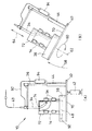
次に、本発明の吸引装置10を説明するに、吸引装置10は、従来型の吸引ノズル34と、この吸引ノズル34を昇降させるためのノズル昇降スタンド36と、粉体を収容した円筒形容器14を回転可能に搭載する回転テーブル装置38と、この回転テーブル装置38をほぼ水平な回転軸40を中心として傾動させる傾動機構42を有する。
【0015】
吸引ノズル34としては、中央吸引管と外側管との間に二次空気供給通路が形成された後述する二重管構造を有する吸引ノズルを使用してもよいし、単管構造の吸引ノズルを使用してもよい。吸引ノズル34は輸送管43によりバキュームコンベヤ12の入口管22に接続される。
ノズル昇降スタンド36は油圧シリンダ44を有し、スタンドに装着された吸引ノズル34を昇降させるようになっている。
【0016】
回転テーブル装置38は、水平回転軸40を中心として傾動可能なベース46と、このベースに回転可能に支持された回転テーブル48とで構成することができる。回転テーブル48は駆動式でも遊動式でもよく、前者の場合には、回転テーブル48は例えば駆動モータ50とベルト伝動機構やギヤ伝動機構その他の伝動機構(図示せず)からなる駆動手段によって駆動される。
【0017】
回転テーブル装置38のベース46を水平回転軸40を中心として傾動させた時に回転テーブル48上の傾斜した円筒形容器14の側壁を側方から支持するため、ベース46には円周方向に離間した例えば3箇所に支持軸52が設けてあり、夫々の支持軸52には遊動式の容器支持ローラ54が回転可能に装着してある。回転テーブル48を遊動式にする場合には、ローラ54を駆動することにより容器14を回転駆動してもよい。
【0018】
傾動機構42は回転テーブル装置38のベース46に連結された油圧シリンダ42で構成することができる。油圧シリンダに代えて、モータ・歯車機構や空圧シリンダを使用することも可能である。
吸引装置10のノズル昇降スタンド36、回転テーブル装置38、油圧シリンダ42、並びに、空気輸送システムのバキュームコンベヤ12および混合機16は、プログラムされた制御装置56によって制御される。
【0019】
次に、本発明の吸引装置10およびそれを備えた空気輸送システムの作動と使用の態様の一例を説明する。容器14内の粉体を混合機16へ移送するに際しては、バキュームコンベヤ12は予め混合機16のいづれかの材料投入口18の上方に位置決めする。
粉体の入った容器14を人手若しくはロボットのような自動化取扱い装置により回転テーブル装置38の回転テーブル48に載置し、容器14の蓋を開ける。
【0020】
次に、油圧シリンダ42を作動させることにより回転テーブル装置38を、それに搭載した容器14ごと、水平回転軸40を中心として図2に矢印58で示したように傾動させると共に、モータ50を駆動して回転テーブル48を回転させることにより容器14を図2に矢印60で示したようにその傾斜した軸線62を中心として回転させる。
傾斜した容器14はその側壁に係合する支持ローラ54によって支承される。
【0021】
ノズル昇降スタンド36の油圧シリンダ44を作動させることにより吸引ノズル34を図2に矢印64で示したように徐々に下降させながら、バキュームコンベヤ12を作動させると、容器14内の粉体は吸引ノズル34により吸引され、輸送管43を介してバキュームコンベヤ12に空気輸送され、バッチ毎にバキュームコンベヤ12から混合機16に投入される。
【0022】
粉体の吸引と輸送が進むにつれて、容器14内の粉体66の残量は少なくなるであろう。回転テーブル装置38の傾動による容器14の傾斜角は、吸引の初期に小さく、粉体残量の減少につれて大きくすることができる。
このように容器14が傾斜していると共に回転駆動されているので、容器14内の粉体66の残量は、図2に示したように、粉体容器14の底の片隅に集まる。
この片隅に向かって吸引ノズル34の先端を所望の制御された速度で下降させることにより、容器14内の粉体を残量の最後まで吸引させることができる。
【0023】
図3は本発明の第2実施例に係る吸引装置を示す。この第2実施例は、粉体吸引中に外部雰囲気中の塵埃が粉体容器内に吸引されないようにしたことを特徴としている。図3においては、図1および図2に示した第1実施例の構成要素と共通する構成要素は同じ参照番号で示し、重複する説明は省略する。
【0024】
図3を参照するに、この実施例においては、回転テーブル装置38とノズル昇降スタンド36とは水平な回転軸40を中心として傾動する共通の基板70に搭載されており、油圧シリンダ42を作動させることにより回転テーブル装置38がノズル昇降スタンド36ごと傾動するようになっている。このように、ノズル昇降スタンド36が傾斜しない第1実施例と異なり、回転テーブル装置38とノズル昇降スタンド36とは等しく傾斜するので、吸引ノズル34は粉体容器14の傾斜に関係なく粉体容器14の軸線に沿って移動させることができる。
【0025】
この実施例では、吸引装置10は、回転テーブル装置38の回転テーブル48に載置された粉体容器14の上部開口を気密に閉鎖するダストカバー72を備えている。吸引ノズル34はこのダストカバー72の中央開口を貫通しており、ノズル昇降スタンド36を作動させることにより吸引ノズル34を昇降させた時に吸引ノズル34がダストカバー72を通って軸方向に摺動するようになっている。
吸引ノズル34とダストカバー72との間をシールするため、ダストカバー72にはエラストマー製のシール部材74が装着してある。
【0026】
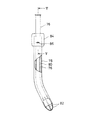
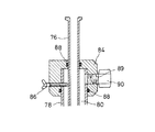
吸引ノズル34は、図4および図5に示したように、中央吸引管76と外側管78からなる二重管構造を有し、中央吸引管76と外側管78との間には二次空気供給通路80が形成されている。
外側管78の下端の内側には例えば金属棒をU字形に折り曲げて形成した2本のガード兼用ガイド82が溶接などにより取付けてある。2本のガード兼用ガイド82はそれらの中央で十字形に交差させてある。夫々のガード兼用ガイド82の対向する2つの自由端は直径方向内側に縮径してあり、中央吸引管76を摺動自在に案内するようになっている。
【0027】
図5に示したように、吸引ノズル34の二次空気供給通路80の上端は外側管78の上端に固定された二次空気ジョイント84によって閉鎖されており、中央吸引管76はこの二次空気ジョイント84を摺動自在に貫通している。中央吸引管76は外側管78に対して多少出入りさせることができ、両者の相対位置は二次空気ジョイント84および外側管78に螺合した蝶ねじ86を中央吸引管76に対して締め付けることにより固定される。二次空気ジョイント84はOリング88によって中央吸引管76および外側管78に対してシールされている。
【0028】
二次空気ジョイント84は二次空気取入口89を有し、この二次空気取入口89にはホース継手90が装着してある。このホース継手90は空気ホース92を介してフィルター94に接続されている(図3)。フィルター94は例えばノズル昇降スタンド36に取付けることができる。
図3および図4から良く分かるように、吸引ノズル34は湾曲させてあり、吸引ノズル34を下降させた時にその先端が粉体容器14の底の片隅に指向するようになっている。
【0029】
次に、この第2実施例の作動を説明するに、粉体を入れた容器14を回転テーブル装置38の回転テーブル48に載置し、容器14の蓋を開けたならば、容器14の上縁にダストカバー72を密着させて容器14を密閉する。
バキュームコンベヤ12を作動させると、バキュームコンベヤの負圧は輸送管43を介して吸引ノズル34の中央吸引管76に印加され、中央吸引管76は粉体容器14内の空気を吸引する。
【0030】
粉体容器14はダストカバー72によって密閉されているので、粉体容器14内の空気の吸引に伴い粉体容器14内が負圧になるにつれて、雰囲気の空気は、フィルター94、空気ホース92、二次空気ジョイント84および二次空気供給通路80を介して粉体容器14内に導入される。その際、空気はフィルター94により濾過されるので、外部雰囲気中の塵埃が粉体容器14内に吸引されることがない。従って、容器内の粉体が外部雰囲気中の塵埃によって汚染されることがない。
【0031】
油圧シリンダ42を伸長させて図3(B)に示したように回転テーブル装置38をノズル昇降スタンド36ごと傾動させながら回転テーブル48を回転させると共に、吸引ノズル34を徐々に下降させると、容器14内の粉体は容器内に導入された二次空気と共に吸引ノズル34から吸引され、バキュームコンベヤ12に空気輸送される。
この第2実施例ではノズル昇降スタンド36は回転テーブル装置38と共に傾動し、吸引ノズル34は粉体容器14の軸線62に平行に移動するので、ダストカバー72とシール部材74によって粉体容器14を密閉しながら吸引ノズル34を下降させることができる。
【0032】
この第2実施例では吸引ノズル34は粉体容器14の底の片隅に向かって湾曲させてあるので、ノズル昇降スタンド36の傾動に伴い吸引ノズル34が傾斜しても容器14内の粉体は完全に吸引される。
【0033】
図示しない最も簡素な実施形態においては、回転テーブル装置を傾動させる傾動機構を省略し、回転テーブル装置自体を傾斜した回転軸線を中心として回転するように最初から傾斜させた状態で設置することができる。
【0034】
以上には本発明の特定の実施例を記載したが、本発明はこれに限定されるものではなく、種々の修正や変更を施すことができる。例えば、粉体容器はクランプ装置やチャッキング装置によって回転テーブルに固定することができ、この場合には支持ローラは不要である。
また、回転テーブル装置に代えて、円筒形粉体容器の下縁を例えば3点支持の形に円周上に配置された複数のフランジ付きローラで支持し、いづれかのローラを駆動することにより容器を回転させることもできる。
【0035】
【発明の効果】
本発明によれば、ドラム缶のような粉体容器を傾斜させかつ回転させることにより、粉体容器内の残留粉体を粉体容器の底の片隅に集めながら吸引するので、最後の残量まで滞りなく吸引することができる。
従って、人手による介入を廃止若しくは最小限にし、粉体の吸引・空気輸送工程をほぼ自動化することに寄与することができる。
【0036】
粉体容器の上部開口を気密に閉鎖するダストカバーを備え、二次空気導入通路を有する二重管構造の吸引ノズルをダストカバーに摺動可能に通過させ、吸引ノズルの二次空気導入通路をフィルターに接続した実施態様においては、粉体吸引中に外部雰囲気中の塵埃が粉体容器内に吸引されないので、医薬品材料や半導体製造材料や食品材料のような高純度が要求され或いは汚染を嫌う材料を取り扱うことができる。
【図面の簡単な説明】
【図1】本発明の第1実施例に係る吸引装置を備えた空気輸送システムの概略的側面図である。
【図2】図1に示した吸引装置の作動状態を示す一部切欠き側面図である。
【図3】本発明の第2実施例に係る吸引装置の側面図で、(A)は容器を搭載したところを示し、(B)は容器を傾斜させたところを示す。
【図4】図3に示した吸引ノズルの一部切欠き側面図である。
【図5】図4のV−V線に沿った拡大断面図である。
【符号の説明】
10: 吸引装置
12: バキュームコンベヤ
14: 粉体容器
34: 吸引ノズル
36: ノズル昇降機構
38: 回転テーブル装置
40: 水平傾動軸線
42: 傾動機構
48: 回転テーブル
50: 回転駆動手段
54: 容器側壁支持ローラ
56: 制御装置
70: 搭載基板
72: ダストカバー
74: シール部材
80: 二次空気供給通路
94: フィルター[0001]
BACKGROUND OF THE INVENTION
The present invention is for sucking powder from a container when pneumatically transporting the powder contained in a cylindrical container such as a drum can formed of a metal such as iron or aluminum, fiber reinforced resin, or paperboard. The present invention relates to a suction device and method.
[0002]
[Prior art]
For transporting and handling various powders, cylindrical powder containers in the form of drums made of metal, fiber reinforced resin, paperboard, etc. are used.
In order to minimize the generation of dust when transferring the powder transported in this type of powder container to a hopper, mixer, or other storage / treatment container, the powder is transferred using a vacuum conveyor. It is desirable to pneumatically transport.
For this reason, a suction nozzle connected to a vacuum conveyor is conventionally used. In this method, the lid of the cylindrical powder container is opened, the suction nozzle is inserted into the powder container, the vacuum conveyor is operated, and the powder is sucked from the cylindrical container by the vacuum.
[0003]
[Problems to be solved by the invention]
As the powder is sucked, the powder around the suction port of the suction nozzle locally disappears in the cylindrical powder container, and the residual powder remains unbalanced and the remaining amount of powder in the container itself. Less. Therefore, the worker must move the suction nozzle so as to stir the powder in the container so that the powder is sucked from the suction nozzle evenly.
For this reason, manpower is indispensable for sucking powder from a cylindrical powder container using a vacuum conveyor, and the suction process cannot be automated.
[0004]
An object of the present invention is to provide a suction device and method capable of eliminating or minimizing manual intervention in sucking powder contained in a cylindrical container.
Another object of the present invention is to provide a suction device and method capable of substantially automating the suction of powder contained in a cylindrical container.
[0005]
Further, in the conventional method, the suction operation using the suction nozzle is performed with the lid of the cylindrical powder container opened, so that air in the external atmosphere is sucked into the powder container, and the powder to be transported is There is a problem that it is contaminated by airborne dust in the atmosphere. For this reason, it has been impossible to handle materials that require high purity such as pharmaceutical materials, semiconductor manufacturing materials, and food materials or that dislike contamination.
Accordingly, another object of the present invention is to provide a suction device and method in which the powder to be transported is not contaminated by suspended dust in the atmosphere.
[0006]
[Means for Solving the Problems]
The present invention provides a suction device for sucking powder contained in a cylindrical container, and this device is a rotation for rotatably mounting a bottomed cylindrical container containing powder. A table device; drive means for rotating the powder container placed on the rotary table device about its axis; and tilting the rotary table device between a horizontal position and an inclined position about a substantially horizontal axis. A tilting mechanism; a suction nozzle connectable to a vacuum conveyor; a nozzle lifting mechanism for moving the suction nozzle back and forth toward the bottom of the powder container placed on the rotary table device; and the driving means, the tilting mechanism, and the nozzle And a control device for controlling the lifting mechanism.
[0007]
In the suction device of the present invention, the powder container is driven to rotate by driving the rotary table by the driving means or directly driving the container while the rotary table device is inclined. Since the powder container is rotated about the axis of the container while tilting the powder container, the residual powder in the powder container is collected at one corner of the bottom of the tilted powder container. Therefore, by positioning the tip of the suction nozzle at this one corner, the residual powder in the powder container can be sucked to the last remaining amount without delay.
[0008]
In another embodiment, the suction device rotates a rotating table device for rotatably mounting a cylindrical powder container with a bottom, and a powder container placed on the rotating table device about its axis. Drive means, suction nozzle connectable to a vacuum conveyor, nozzle lifting mechanism for moving the suction nozzle back and forth toward the bottom of the powder container placed on the rotary table device, rotary table device and nozzle lifting mechanism , A tilting mechanism that tilts the board between a horizontal position and an inclined position about a substantially horizontal axis, and a control device that controls the driving means, the nozzle lifting mechanism, and the tilting mechanism. Yes.
[0009]
In this embodiment, the powder container is tilted together with the nozzle lifting mechanism by tilting the substrate on which the rotary table device and the nozzle lifting mechanism are mounted. By rotating and driving the inclined powder container, the residual powder in the powder container is sucked by the suction nozzle while collecting in the bottom corner of the inclined powder container as in the first embodiment. .
[0010]
In a preferred embodiment, the suction device further includes a dust cover that hermetically closes the upper opening of the powder container placed on the rotary table device, and the suction nozzle passes through the dust cover opening in a slidable and airtight manner. The suction nozzle has a double tube structure in which a central suction passage and an outer secondary air introduction passage are formed, and the suction device further includes a filter connected to the inlet of the secondary air introduction passage of the suction nozzle. ing.
In this way, since dust in the external atmosphere is not sucked into the powder container during powder suction, contamination of powder by dust can be avoided.
[0011]
In another aspect, the present invention provides a method of sucking a powder contained in a bottomed cylindrical container with a suction nozzle, and this method comprises rotating the container while tilting the container. The residual powder inside is collected in one corner of the bottom of the container and sucked by a suction nozzle positioned in this one corner.
[0012]
DETAILED DESCRIPTION OF THE INVENTION
FIG. 1 shows a non-limiting layout of a pneumatic transport system using the suction device of the present invention.
Referring to FIG. 1, this pneumatic transport system includes a
[0013]
Since the
The
The
[0014]
Next, the
[0015]
As the
The nozzle raising / lowering
[0016]
The
[0017]
When the
[0018]
The
The nozzle lifting stand 36 of the
[0019]
Next, an example of the mode of operation and use of the
The
[0020]
Next, by actuating the
The
[0021]
When the
[0022]
As powder suction and transport progresses, the remaining amount of
Since the
By lowering the tip of the
[0023]
FIG. 3 shows a suction device according to a second embodiment of the present invention. The second embodiment is characterized in that dust in the external atmosphere is not sucked into the powder container during powder suction. In FIG. 3, the same components as those of the first embodiment shown in FIGS. 1 and 2 are denoted by the same reference numerals, and a duplicate description is omitted.
[0024]
Referring to FIG. 3, in this embodiment, the
[0025]
In this embodiment, the
In order to seal between the
[0026]
As shown in FIGS. 4 and 5, the
Inside the lower end of the
[0027]
As shown in FIG. 5, the upper end of the secondary
[0028]
The secondary air joint 84 has a
As can be clearly seen from FIGS. 3 and 4, the
[0029]
Next, the operation of the second embodiment will be described. When the
When the
[0030]
Since the
[0031]
When the
In this second embodiment, the nozzle raising / lowering
[0032]
In this second embodiment, the
[0033]
In the simplest embodiment (not shown), the tilting mechanism for tilting the turntable device can be omitted, and the turntable device itself can be installed in a state of being tilted from the beginning so as to rotate around the tilted rotation axis. .
[0034]
Although specific embodiments of the present invention have been described above, the present invention is not limited to them, and various modifications and changes can be made. For example, the powder container can be fixed to the rotary table by a clamping device or a chucking device, and in this case, a support roller is unnecessary.
Further, instead of the rotary table device, the lower edge of the cylindrical powder container is supported by, for example, a plurality of flanged rollers arranged on the circumference in a three-point support form, and one of the rollers is driven to drive the container. Can also be rotated.
[0035]
【Effect of the invention】
According to the present invention, by tilting and rotating a powder container such as a drum can, the residual powder in the powder container is sucked while being collected in one corner of the bottom of the powder container. Suction can be performed without delay.
Accordingly, it is possible to eliminate or minimize manual intervention, and to contribute to substantially automating the powder suction / pneumatic transport process.
[0036]
A dust cover that hermetically closes the upper opening of the powder container is provided, and a suction nozzle having a double-pipe structure having a secondary air introduction passage is slidably passed through the dust cover. In the embodiment connected to the filter, dust in the external atmosphere is not sucked into the powder container during the suction of the powder, so high purity such as pharmaceutical materials, semiconductor manufacturing materials and food materials is required or contamination is disliked. Material can be handled.
[Brief description of the drawings]
FIG. 1 is a schematic side view of an air transportation system including a suction device according to a first embodiment of the present invention.
2 is a partially cutaway side view showing an operating state of the suction device shown in FIG. 1. FIG.
FIGS. 3A and 3B are side views of a suction device according to a second embodiment of the present invention, in which FIG. 3A shows a place where a container is mounted, and FIG. 3B shows a place where the container is tilted.
4 is a partially cutaway side view of the suction nozzle shown in FIG. 3;
FIG. 5 is an enlarged cross-sectional view taken along line VV in FIG.
[Explanation of symbols]
DESCRIPTION OF SYMBOLS 10: Suction apparatus 12: Vacuum conveyor 14: Powder container 34: Suction nozzle 36: Nozzle raising / lowering mechanism 38: Rotary table apparatus 40: Horizontal tilt axis 42: Tilt mechanism 48: Rotary table 50: Rotation drive means 54: Container side wall support Roller 56: Control device 70: Mounting substrate 72: Dust cover 74: Seal member 80: Secondary air supply passage 94: Filter
Claims (7)
粉体を収容した有底円筒形の容器を回転可能に搭載するための回転テーブル装置と、
前記回転テーブル装置に載置された前記粉体容器をその軸線を中心として回転させる駆動手段と、
前記回転テーブル装置をほぼ水平な軸線を中心として水平位置と傾斜位置との間で傾動させる傾動機構と、
バキュームコンベヤに接続可能な吸引ノズルと、
前記回転テーブル装置に載置された前記粉体容器の底に向かって前記吸引ノズルを進退させるためのノズル昇降機構と、
前記駆動手段、傾動機構およびノズル昇降機構を制御する制御装置とを備え、
前記回転テーブル装置を傾斜させながら前記粉体容器を回転駆動することにより、粉体容器内の残留粉体を傾斜した粉体容器の底の片隅に集めながら吸引ノズルによって吸引するようにしたことを特徴とする吸引装置。A suction device for sucking powder contained in a bottomed cylindrical container:
A rotary table device for rotatably mounting a cylindrical container with a bottom containing powder,
Drive means for rotating the powder container placed on the rotary table device about its axis;
A tilt mechanism for tilting the rotary table device between a horizontal position and a tilt position about a substantially horizontal axis;
A suction nozzle that can be connected to a vacuum conveyor;
A nozzle lifting mechanism for moving the suction nozzle forward and backward toward the bottom of the powder container placed on the rotary table device;
A controller for controlling the driving means, the tilting mechanism and the nozzle lifting mechanism;
The powder container is driven to rotate while the rotary table device is tilted so that the residual powder in the powder container is sucked by the suction nozzle while being collected at one corner of the bottom of the tilted powder container. Suction device characterized.
粉体を収容した有底円筒形の容器を回転可能に搭載するための回転テーブル装置と、
前記回転テーブル装置に載置された前記粉体容器をその軸線を中心として回転させる駆動手段と、
バキュームコンベヤに接続可能な吸引ノズルと、
前記回転テーブル装置に載置された前記粉体容器の底に向かって前記吸引ノズルを進退させるためのノズル昇降機構と、
前記回転テーブル装置およびノズル昇降機構を搭載した基板と、
前記基板をほぼ水平な軸線を中心として水平位置と傾斜位置との間で傾動させる傾動機構と、
前記駆動手段、ノズル昇降機構および傾動機構を制御する制御装置とを備え、
前記基板を傾斜させながら前記粉体容器を回転駆動することにより、粉体容器内の残留粉体を傾斜した粉体容器の底の片隅に集めながら吸引ノズルによって吸引するようにしたことを特徴とする吸引装置。A suction device for sucking powder contained in a bottomed cylindrical container:
A rotary table device for rotatably mounting a cylindrical container with a bottom containing powder,
Drive means for rotating the powder container placed on the rotary table device about its axis;
A suction nozzle that can be connected to a vacuum conveyor;
A nozzle lifting mechanism for moving the suction nozzle forward and backward toward the bottom of the powder container placed on the rotary table device;
A substrate on which the rotary table device and the nozzle lifting mechanism are mounted;
A tilt mechanism for tilting the substrate between a horizontal position and a tilt position about a substantially horizontal axis;
A controller for controlling the driving means, the nozzle lifting mechanism and the tilting mechanism;
The powder container is rotated while the substrate is tilted, and the residual powder in the powder container is sucked by a suction nozzle while being collected in one corner of the tilted powder container. Suction device to do.
前記吸引ノズルは前記ダストカバーの開口を摺動可能かつ気密に通過しており、
前記吸引ノズルは中央吸引通路と外側二次空気導入通路とが形成された二重管構造を有し、
前記装置は吸引ノズルの前記二次空気導入通路の入口に接続されたフィルターを更に備え、
もって、粉体吸引中に外部雰囲気中の塵埃が粉体容器内に吸引されないようにしたことを特徴とする請求項2に基づく吸引装置。The apparatus further includes a dust cover that hermetically closes an upper opening of a powder container placed on the rotary table device,
The suction nozzle passes slidably and airtightly through the opening of the dust cover,
The suction nozzle has a double pipe structure in which a central suction passage and an outer secondary air introduction passage are formed;
The apparatus further comprises a filter connected to the inlet of the secondary air introduction passage of the suction nozzle,
Thus, the suction device according to claim 2, wherein dust in the external atmosphere is not sucked into the powder container during powder suction.
傾斜した回転軸線を有し、粉体を収容した有底円筒形の容器を回転可能に搭載するための回転支持装置と、
前記回転支持装置に載置された粉体容器をその軸線を中心として回転させる駆動手段と、
バキュームコンベヤに接続可能な吸引ノズルと、
前記回転支持装置に載置された前記粉体容器の底に向かって前記吸引ノズルを進退させるためのノズル昇降機構と、
前記駆動手段およびノズル昇降機構を制御する制御装置とを備え、
粉体容器を傾斜した回転軸線を中心として回転駆動することにより、粉体容器内の残留粉体を粉体容器の底の片隅に集めながら吸引ノズルによって吸引するようにしたことを特徴とする吸引装置。A suction device for sucking powder contained in a bottomed cylindrical container:
A rotation support device for rotatably mounting a bottomed cylindrical container having a tilted rotation axis and containing powder;
Drive means for rotating the powder container placed on the rotation support device about its axis;
A suction nozzle that can be connected to a vacuum conveyor;
A nozzle lifting mechanism for moving the suction nozzle back and forth toward the bottom of the powder container placed on the rotation support device;
A controller for controlling the driving means and the nozzle lifting mechanism;
The suction is characterized in that the powder container is driven to rotate around an inclined rotation axis so that the residual powder in the powder container is sucked by a suction nozzle while being collected in one corner of the bottom of the powder container. apparatus.
7. When the powder contained in the bottomed cylindrical container is sucked by the suction nozzle by the suction device according to claim 1 , the powder remaining in the container is rotated by rotating the container while inclining the powder. Is collected in one corner of the bottom of the container and sucked by a suction nozzle positioned in the one corner.
Priority Applications (1)
| Application Number | Priority Date | Filing Date | Title |
|---|---|---|---|
| JP2001265643A JP4875261B2 (en) | 2001-09-03 | 2001-09-03 | Apparatus and method for sucking powder in cylindrical container |
Applications Claiming Priority (1)
| Application Number | Priority Date | Filing Date | Title |
|---|---|---|---|
| JP2001265643A JP4875261B2 (en) | 2001-09-03 | 2001-09-03 | Apparatus and method for sucking powder in cylindrical container |
Publications (2)
| Publication Number | Publication Date |
|---|---|
| JP2003072954A JP2003072954A (en) | 2003-03-12 |
| JP4875261B2 true JP4875261B2 (en) | 2012-02-15 |
Family
ID=19092079
Family Applications (1)
| Application Number | Title | Priority Date | Filing Date |
|---|---|---|---|
| JP2001265643A Expired - Lifetime JP4875261B2 (en) | 2001-09-03 | 2001-09-03 | Apparatus and method for sucking powder in cylindrical container |
Country Status (1)
| Country | Link |
|---|---|
| JP (1) | JP4875261B2 (en) |
Families Citing this family (5)
| Publication number | Priority date | Publication date | Assignee | Title |
|---|---|---|---|---|
| JP2006168852A (en) * | 2004-12-13 | 2006-06-29 | Akatake Engineering Kk | Device for sucking-out powder inside bag |
| JP4979618B2 (en) * | 2008-03-07 | 2012-07-18 | 株式会社クボタ | Rice transfer mechanism of rice washing machine |
| JP4979619B2 (en) * | 2008-03-07 | 2012-07-18 | 株式会社クボタ | Rice transfer mechanism of rice washing machine |
| WO2011070668A1 (en) | 2009-12-10 | 2011-06-16 | 新東工業株式会社 | Suction device for powder and suction system and method for powder |
| CN110871926A (en) * | 2018-09-04 | 2020-03-10 | 楚天科技股份有限公司 | Powder filling device and racking machine based on different shaft drives |
Family Cites Families (3)
| Publication number | Priority date | Publication date | Assignee | Title |
|---|---|---|---|---|
| JPS52111182A (en) * | 1976-03-16 | 1977-09-17 | Kansai Paint Co Ltd | Transportation supply method of powder paint |
| JPS6211825A (en) * | 1985-07-10 | 1987-01-20 | Nippon Soda Co Ltd | Liquid crystal cell sealing agent and production of liquid crystal cell |
| JP4001356B2 (en) * | 1999-11-08 | 2007-10-31 | 株式会社リコー | Suction type powder transport device |
-
2001
- 2001-09-03 JP JP2001265643A patent/JP4875261B2/en not_active Expired - Lifetime
Also Published As
| Publication number | Publication date |
|---|---|
| JP2003072954A (en) | 2003-03-12 |
Similar Documents
| Publication | Publication Date | Title |
|---|---|---|
| US7168460B2 (en) | Apparatus for decanting pulverulent product and method which can be carried out using said apparatus | |
| JP5665741B2 (en) | Positioning apparatus and method using a rotary indexing table for monolith-based automotive and chemical catalysts | |
| KR101574357B1 (en) | Industrial robot | |
| JP5107340B2 (en) | Apparatus and method for feeding product to packaging machine | |
| WO1998038672A1 (en) | System for loading, processing and unloading substrates arranged on a carrier | |
| JPS604094B2 (en) | Pneumatic tube device for fine substance samples | |
| WO1998026244A1 (en) | Vacuum rotary dryer | |
| JP4875261B2 (en) | Apparatus and method for sucking powder in cylindrical container | |
| JPH0846013A (en) | Multichamber treatment system conveyer | |
| JPH07142551A (en) | Carrier arm device and processing chamber collector using carrier arm device | |
| WO1997017728A1 (en) | Transfer device, transfer method, processing device, and processing method | |
| KR19980042623A (en) | Cassette Carrying Mechanism | |
| JP4664481B2 (en) | Powder unloading device | |
| JP3728703B2 (en) | Dissimilar powder mixing equipment | |
| JPH10280144A (en) | Loading/unloading of evacuatable process chamber and apparatus for executing the same | |
| JP2626954B2 (en) | Method and apparatus for automatically charging and discharging powder material | |
| JP3638393B2 (en) | Substrate processing equipment | |
| JP3154784B2 (en) | Method of transporting powdery and granular materials in bulk and unloading device | |
| JPH07165223A (en) | Automatic bag-opening system | |
| CN1704324A (en) | Apparatus for filling powder type mineral aggregate and execution method for using the same | |
| JPS63252805A (en) | Granule handling system | |
| JPS6221014Y2 (en) | ||
| CN114655723A (en) | Powder processing apparatus including a loading and unloading system | |
| JP2023039809A (en) | Feed device for rotary kiln, and rotary kiln | |
| JPH05270656A (en) | Material conveyor device |
Legal Events
| Date | Code | Title | Description |
|---|---|---|---|
| A621 | Written request for application examination |
Free format text: JAPANESE INTERMEDIATE CODE: A621 Effective date: 20080818 |
|
| A977 | Report on retrieval |
Free format text: JAPANESE INTERMEDIATE CODE: A971007 Effective date: 20110104 |
|
| A131 | Notification of reasons for refusal |
Free format text: JAPANESE INTERMEDIATE CODE: A131 Effective date: 20110712 |
|
| A521 | Written amendment |
Free format text: JAPANESE INTERMEDIATE CODE: A523 Effective date: 20110825 |
|
| TRDD | Decision of grant or rejection written | ||
| A01 | Written decision to grant a patent or to grant a registration (utility model) |
Free format text: JAPANESE INTERMEDIATE CODE: A01 Effective date: 20111122 |
|
| A01 | Written decision to grant a patent or to grant a registration (utility model) |
Free format text: JAPANESE INTERMEDIATE CODE: A01 |
|
| A61 | First payment of annual fees (during grant procedure) |
Free format text: JAPANESE INTERMEDIATE CODE: A61 Effective date: 20111125 |
|
| FPAY | Renewal fee payment (event date is renewal date of database) |
Free format text: PAYMENT UNTIL: 20141202 Year of fee payment: 3 |
|
| R150 | Certificate of patent or registration of utility model |
Ref document number: 4875261 Country of ref document: JP Free format text: JAPANESE INTERMEDIATE CODE: R150 Free format text: JAPANESE INTERMEDIATE CODE: R150 |
|
| R250 | Receipt of annual fees |
Free format text: JAPANESE INTERMEDIATE CODE: R250 |
|
| R250 | Receipt of annual fees |
Free format text: JAPANESE INTERMEDIATE CODE: R250 |
|
| R250 | Receipt of annual fees |
Free format text: JAPANESE INTERMEDIATE CODE: R250 |
|
| R250 | Receipt of annual fees |
Free format text: JAPANESE INTERMEDIATE CODE: R250 |
|
| R250 | Receipt of annual fees |
Free format text: JAPANESE INTERMEDIATE CODE: R250 |
|
| R250 | Receipt of annual fees |
Free format text: JAPANESE INTERMEDIATE CODE: R250 |
|
| R250 | Receipt of annual fees |
Free format text: JAPANESE INTERMEDIATE CODE: R250 |
|
| EXPY | Cancellation because of completion of term |