JP4874771B2 - Ionizer - Google Patents
Ionizer Download PDFInfo
- Publication number
- JP4874771B2 JP4874771B2 JP2006323596A JP2006323596A JP4874771B2 JP 4874771 B2 JP4874771 B2 JP 4874771B2 JP 2006323596 A JP2006323596 A JP 2006323596A JP 2006323596 A JP2006323596 A JP 2006323596A JP 4874771 B2 JP4874771 B2 JP 4874771B2
- Authority
- JP
- Japan
- Prior art keywords
- carrier gas
- main body
- body case
- high voltage
- casing
- Prior art date
- Legal status (The legal status is an assumption and is not a legal conclusion. Google has not performed a legal analysis and makes no representation as to the accuracy of the status listed.)
- Expired - Fee Related
Links
Images


Classifications
-
- H—ELECTRICITY
- H01—ELECTRIC ELEMENTS
- H01T—SPARK GAPS; OVERVOLTAGE ARRESTERS USING SPARK GAPS; SPARKING PLUGS; CORONA DEVICES; GENERATING IONS TO BE INTRODUCED INTO NON-ENCLOSED GASES
- H01T23/00—Apparatus for generating ions to be introduced into non-enclosed gases, e.g. into the atmosphere
-
- H—ELECTRICITY
- H01—ELECTRIC ELEMENTS
- H01T—SPARK GAPS; OVERVOLTAGE ARRESTERS USING SPARK GAPS; SPARKING PLUGS; CORONA DEVICES; GENERATING IONS TO BE INTRODUCED INTO NON-ENCLOSED GASES
- H01T19/00—Devices providing for corona discharge
Description
本発明は、正又は負に帯電している帯電体の電荷を除電するためのイオン化装置に関する。 The present invention relates to an ionization apparatus for removing charges of a charged body charged positively or negatively.
クリーンルームでの清浄化や浮遊粒子の帯電防止など、空気中の静電気制御のために静電気除去(除電)が行われているが、この非接触の除電に、コロナ放電式のイオン化装置が多用されている。 Static electricity removal (static elimination) is performed to control static electricity in the air, such as cleaning in a clean room and preventing static charge of suspended particles. Corona discharge ionization devices are often used for this non-contact static elimination. Yes.
コロナ放電式の除電装置は、放電用の電極針に高電圧電源からの直流高電圧又は交流高電圧を印加してコロナ放電を生じさせる。図23に除電装置の概略図を示す。この図に示す除電装置は、コロナ放電を生じさせる放電電極1と、交流電源に接続された高圧電源部2と、放電電極1と高圧電源部2とを接続するカップリングコンデンサ3とを備える。除電装置は、交流電源で高圧電源部2である高圧トランス2Aを駆動し、放電電極1に高電圧を印加してコロナ放電を生じさせる。コロナ放電によって放電電極1の周辺に存在する空気は電離され、プラス又はマイナスのイオンを発生させる。電離した空気のイオンは除電装置に設けられたファン等で送風されて対象物まで搬送される。プラスイオンやマイナスイオンで対象物の帯電電位が中和されることにより、対象物に蓄積されている帯電電荷はゼロに近づき、除電される。
A corona discharge type static eliminator applies a DC high voltage or an AC high voltage from a high voltage power source to a discharge electrode needle to generate a corona discharge. FIG. 23 shows a schematic diagram of the static eliminator. The static eliminator shown in this figure includes a
除電装置で発生されて空気中を流れるプラス、又はマイナスのイオン流は、高電圧電源とアース間の電流として考えることができる。すなわち、高電圧電源からアースに向かって流れる電流はマイナスのイオン流に相当し、アースから高電圧発生部に向かって流れる電流はプラスのイオン流に相当している。このようなイオン流と電流との相互関係により、除電装置から発生しているプラス、マイナスのイオン量が同数であれば中和されて電流はゼロとなる。したがって、除電装置は発生されるプラス、マイナスのイオン量のバランス(イオンバランス)を維持することで正しく除電を実行できる。 The positive or negative ion flow generated in the static eliminator and flowing in the air can be considered as a current between the high voltage power source and the ground. That is, the current flowing from the high voltage power source toward the ground corresponds to a negative ion flow, and the current flowing from the ground toward the high voltage generating unit corresponds to a positive ion flow. Due to the mutual relationship between the ion current and the current, if the number of positive and negative ions generated from the static eliminator is the same, neutralization is performed and the current becomes zero. Therefore, the static eliminator can correctly perform the static elimination by maintaining the balance between the generated positive and negative ion amounts (ion balance).
例えば、従来のイオン化装置として図24〜図27に示すような所謂バータイプの除電器が知られている。これらの図において図24はイオン化装置の外観を示す斜視図、図25は分解斜視図、図26は断面図、図27はブロック図を、それぞれ示している。これらの図に示すイオン化装置は、放電電極バーで構成され、本体ケース10内の上方領域に、高電圧ユニット213等が配置され、下方領域にイオンを搬送する空気を供給するエア供給ユニット211が配置されている。電極組立体236をエア供給ユニット211に装着すると、高電圧配板258の切り起こし接触片259と電極針212の上端面とが接触する。電極針212と切り起こし接触片259との接触部分を含む領域は、支持プレートの第1スリーブ229の中に電極組立体236の小径内筒部分240の先端部分が嵌入することにより、エア供給ユニット211の密閉空間つまり主エア通路S1及び円筒状分岐エア通路245から隔絶された独立した密閉空間S2となる。
除電装置が求められる環境に応じて、要求される除電能力は異なる。具体的には、必要な除電エリアに応じて放電電極の数が決定される。しかしながら、要求される放電電極の数毎に個別に放電電極バーを用意するのでは、各々新たな設計が必要となりコストが高くなるという問題がある。そこで、数個の放電電極を持つ放電電極バーを複数本連結して、所望の数の放電電極を備える除電装置を実現することが行われている。 Depending on the environment where a static eliminator is required, the required static eliminability is different. Specifically, the number of discharge electrodes is determined according to the necessary static elimination area. However, if the discharge electrode bar is separately prepared for each required number of discharge electrodes, there is a problem that a new design is required and the cost is increased. In view of this, a plurality of discharge electrode bars having several discharge electrodes are connected to realize a static eliminator including a desired number of discharge electrodes.
しかしながら、従来の放電電極バーは金属部品を多用しており比較的重いため、連結部分での強度を維持するためにある程度の機械的補強が必要となる。強度を維持するためには、金属部品等で連結用部材を構成する必要があるため、さらに装置全体が重く大型化するという問題があった。 However, since the conventional discharge electrode bar uses a lot of metal parts and is relatively heavy, a certain amount of mechanical reinforcement is required to maintain the strength at the connecting portion. In order to maintain the strength, it is necessary to form the connecting member with a metal part or the like, and there is a problem that the entire apparatus is further heavy and large.
これに対処するため、連結構造を補強することも考えられるが、本体ケース自体の剛性が不足すると、この方法では足りず、本体ケース自体を金属などで強化する必要があり、ケースの長大化、重量増を招く。特に最近では、大型の装置にも対応できる除電能力の高い、より多くの放電電極を備えるイオン化装置が求められている。またイオン化装置が長くなると、帯電したイオンを搬送する空気の供給経路が長くなるため、長さ方向に沿って各放電電極に対して十分な空気を均一に供給することも困難となる。さらに、安全性の確保も問題となる。 In order to cope with this, it is conceivable to reinforce the connection structure, but if the rigidity of the main body case itself is insufficient, this method is not sufficient, and it is necessary to strengthen the main body case itself with metal, etc. Incurs weight gain. In particular, recently, there is a demand for an ionization apparatus having a larger number of discharge electrodes, which has a high charge-removing capability and can be used for a large apparatus. In addition, when the ionization apparatus becomes longer, the air supply path for transporting charged ions becomes longer, so that it becomes difficult to uniformly supply sufficient air to each discharge electrode along the length direction. Furthermore, ensuring safety is also a problem.
本発明は、このような問題点を解決するためになされたものである。本発明の主な目的は、連結部分の剛性を高めたイオン化装置を提供することにある。 The present invention has been made to solve such problems. A main object of the present invention is to provide an ionization apparatus with increased rigidity of a connecting portion.
以上の目的を達成するために本発明の第1のイオン化装置は、高電圧を印加されて先端から正負いずれかに帯電したイオンを放出するための複数の電極針と、電極針に高電圧を印加するための電気回路ユニットと、細長形状のユニット状に構成され、電気回路ユニットから電力供給を受けるための高電圧配板を備えると共に、複数の電極針を離間させて装着可能で、高電圧配板を介して電気回路ユニットから供給された高電圧を各々の電極針に印加するケーシング部材と、複数のケーシング部材を長手方向に機械的に連結すると共に、各ケーシング部材の高電圧配板同士を電気的に接続するための連結部材と、連結部材で複数のケーシング部材を連結させたケーシング体及び電気回路ユニットを内部に収納する細長形状の本体ケースであって、電極針を長手方向に離間させて外部に突出させる本体ケースとを備えるイオン化装置であって、本体ケースは、内部にケーシング体を配置するための空間を一体に区画し、電気回路ユニットを配置する空間と隔離されており、前記本体ケースは、第1ケースと、第2ケースとに分割され、前記第1ケースは、一体に形成された断面コ字状部分と、前記断面コ字状部分の背面の一端から一体的に延長された第1の壁面とを備え、前記第2ケースは、前記コ字状部分の背面と当接し、かつ前記第1の壁面の先端と当接する第2の壁面を備え、前記第1ケースと第2ケースを嵌合させた状態で、前記断面コ字状部分で形成される第1の空間に前記ケーシング体を配置し、前記断面コ字状部分の背面と、前記第1の壁面と、第2の壁面の内側で形成される第2の空間に、前記電気回路ユニットを配置するよう構成している。これにより、高電圧が印加されるケーシング体を、低電圧の部分を含む電気回路ユニットと隔離して不要な放電を回避できる。 In order to achieve the above object, a first ionization apparatus of the present invention includes a plurality of electrode needles for discharging ions charged positively or negatively from a tip by applying a high voltage, and applying a high voltage to the electrode needles. An electric circuit unit for applying and a high voltage distribution board for receiving power supply from the electric circuit unit, and a plurality of electrode needles can be mounted apart from each other, and can be mounted with a high voltage. A casing member that applies a high voltage supplied from the electric circuit unit to the electrode needles via the distribution board, and a plurality of casing members are mechanically connected in the longitudinal direction, and the high voltage distribution boards of each casing member are connected to each other. A connecting member for electrically connecting the casing member, a casing body in which a plurality of casing members are connected by the connecting member, and an elongated main body case for housing an electric circuit unit therein. An ionization device comprising a main body case for separating electrode needles in the longitudinal direction and projecting to the outside, wherein the main body case integrally divides a space for disposing a casing body therein and disposes an electric circuit unit. The main body case is divided into a first case and a second case, and the first case includes an integrally formed U-shaped section and a U-shaped section. A first wall surface integrally extended from one end of the back surface, and the second case is in contact with the back surface of the U-shaped portion and is in contact with the tip of the first wall surface. The casing body is disposed in a first space formed by the U-shaped section in a state in which the first case and the second case are fitted, and the back surface of the U-shaped section. , Formed on the inside of the first wall and the second wall The second space is configured to place the electrical circuit unit. Accordingly, unnecessary discharge can be avoided by isolating the casing body to which the high voltage is applied from the electric circuit unit including the low voltage portion.
また、一体に形成された断面コ字状によって長手方向に延長されたイオン化装置の長さ方向における十分な剛性を発揮することができる。さらに、断面コ字状部分でケーシング体を区画することにより、高電圧が印加されるケーシング体と、低電圧の部分を含む電気回路ユニットとの電位差による沿面放電経路を長くして、沿面放電の発生を回避できる。 Moreover , sufficient rigidity in the length direction of the ionizer extended in the longitudinal direction can be exhibited by the integrally formed U-shaped cross section. Furthermore, by dividing the casing body with a U-shaped section, the creeping discharge path due to the potential difference between the casing body to which the high voltage is applied and the electric circuit unit including the low voltage part is lengthened, and the creeping discharge is caused. Occurrence can be avoided.
第2のイオン化装置は、電極針から放出されるイオンを搬送するための搬送ガスを電極針の周囲から送出するために、ケーシング部材は、搬送ガスを供給するための搬送ガス経路を備えており、本体ケースは、本体ケース内部の中間に位置する一以上のケーシング部材に対して、搬送ガスを供給する中間搬送ガス配管を備えており、本体ケース内部の端部に位置するケーシング部材に対しては、本体ケースの端部から搬送ガス経路に搬送ガスが供給され、本体ケース内部の中間に位置するケーシング部材に対しては、中間搬送ガス配管を介して搬送ガスが供給されるよう構成できる。これにより、複数のケーシング部材を連結して長手方向に延長されたイオン化装置において、中間に位置するケーシング部材への搬送ガス供給が不十分となる事態を回避し、各ケーシング部材に安定して搬送ガスを供給できる。 In the second ionization apparatus, the casing member includes a carrier gas path for supplying a carrier gas in order to send a carrier gas for carrying ions emitted from the electrode needle from the periphery of the electrode needle. The main body case is provided with an intermediate carrier gas pipe for supplying carrier gas to one or more casing members located in the middle of the main body case, and with respect to the casing member located at the end inside the main body case. The carrier gas is supplied to the carrier gas path from the end of the main body case, and the carrier gas is supplied to the casing member located in the middle of the main body case via the intermediate carrier gas pipe. As a result, in an ionization apparatus extended in the longitudinal direction by connecting a plurality of casing members, a situation in which the supply of the carrier gas to the casing member located in the middle is insufficient is prevented, and the casing member is stably transported to each casing member. Gas can be supplied.
本発明の実施の形態に係るイオン化装置は、中間搬送ガス配管を、硬質製のパイプで構成できる。これにより、剛性の高い硬質製のパイプを本体ケース内部で長手方向に延長することにより、ゴム製のパイプに比べ長手方向の剛性補強に寄与できる。
第3のイオン化装置は、高電圧を印加されて先端から正負いずれかに帯電したイオンを放出するための複数の電極針と、前記電極針に高電圧を印加するための電気回路ユニットと、細長形状のユニット状に構成され、前記電気回路ユニットから電力供給を受けるための高電圧配板を備えると共に、前記複数の電極針を離間させて装着可能で、前記高電圧配板を介して前記電気回路ユニットから供給された高電圧を各々の電極針に印加するケーシング部材と、複数のケーシング部材を長手方向に機械的に連結すると共に、各ケーシング部材の高電圧配板同士を電気的に接続するための連結部材と、前記連結部材で複数のケーシング部材を連結させたケーシング体及び前記電気回路ユニットを内部に収納する細長形状の本体ケースであって、前記電極針を長手方向に離間させて外部に突出させる本体ケースとを備えるイオン化装置であって、前記本体ケースは、内部に前記ケーシング体を配置するための空間を一体に区画し、前記電気回路ユニットを配置する空間と隔離されており、前記電極針から放出されるイオンを搬送するための搬送ガスを前記電極針の周囲から送出するために、前記ケーシング部材は、搬送ガスを供給するための搬送ガス経路を備えており、前記本体ケースは、本体ケース内部の中間に位置する一以上のケーシング部材に対して、搬送ガスを供給する中間搬送ガス配管を備えており、前記本体ケース内部の端部に位置するケーシング部材に対しては、前記本体ケースの端部から搬送ガス経路に搬送ガスが供給され、前記本体ケース内部の中間に位置するケーシング部材に対しては、中間搬送ガス配管を介して搬送ガスが供給されるよう構成しており、前記電気回路ユニットが、前記本体ケース内部の一端側に配置され、他端側に前記中間搬送ガス配管を配置するよう構成できる。これにより、本体ケースの内部空間に電気回路ユニットと中間搬送ガス配管をバランス良く配置でき、本体ケースを大型化することなく限られたスペースを効率的に利用できる。
In the ionization apparatus according to the embodiment of the present invention , the intermediate carrier gas pipe can be constituted by a hard pipe. Thereby, by extending the rigid rigid pipe in the longitudinal direction inside the main body case, it is possible to contribute to the longitudinal rigidity reinforcement as compared with the rubber pipe.
The third ionization apparatus includes a plurality of electrode needles for discharging ions charged positively or negatively from a tip by applying a high voltage, an electric circuit unit for applying a high voltage to the electrode needles, And a high voltage distribution board configured to receive power from the electric circuit unit, and the plurality of electrode needles can be mounted separately from each other, and the electric voltage is supplied via the high voltage distribution board. A casing member for applying a high voltage supplied from the circuit unit to each electrode needle and a plurality of casing members are mechanically coupled in the longitudinal direction, and the high voltage distribution boards of each casing member are electrically connected to each other. An elongated main body case for housing the electrical circuit unit and a casing body in which a plurality of casing members are coupled by the coupling member, and the electrical circuit unit. An ionization apparatus comprising: a main body case for separating pole needles in the longitudinal direction and projecting to the outside, wherein the main body case integrally partitions a space for arranging the casing body therein, and the electric circuit unit In order to deliver a carrier gas for transporting ions emitted from the electrode needle from the periphery of the electrode needle, the casing member is transported to supply the carrier gas. The main body case includes an intermediate carrier gas pipe for supplying carrier gas to one or more casing members located in the middle of the main body case, and an end portion inside the main body case. For the casing member located in the case, the carrier gas is supplied to the carrier gas path from the end of the body case, and the casing is located in the middle of the body case. The member is configured to be supplied with a carrier gas via an intermediate carrier gas pipe, and the electric circuit unit is disposed on one end side inside the main body case, and the intermediate carrier gas is disposed on the other end side. It can be configured to arrange piping. Accordingly, the electric circuit unit and the intermediate carrier gas pipe can be arranged in a balanced manner in the internal space of the main body case, and the limited space can be efficiently used without increasing the size of the main body case.
第4のイオン化装置は、連結部材が、本体ケースの長手方向に沿ってケーシング部材を挿抜して連結する継ぎ手とできる。これにより、ケーシング部材の長手方向の寸法誤差を、継ぎ手への挿入量により調整することが可能となる。 In the fourth ionization apparatus, the connecting member can be a joint that inserts and removes the casing member along the longitudinal direction of the main body case. As a result, the dimensional error in the longitudinal direction of the casing member can be adjusted by the amount of insertion into the joint.
第5のイオン化装置は、継ぎ手が、本体ケース内部の中間に位置するケーシング部材同士の接続に使用され、中間搬送ガス配管を接続するための搬送ガス供給用継ぎ手を含むことができる。これにより、ケーシング部材同士の連結と、中間搬送ガス配管の接続とを一の継ぎ手で行うことができ、構成の簡素化及び組み立て工程の省力化が図られる。 In the fifth ionization apparatus, the joint is used to connect the casing members positioned in the middle of the main body case, and can include a carrier gas supply joint for connecting the intermediate carrier gas pipe. Thereby, connection of casing members and connection of intermediate conveyance gas piping can be performed by one joint, and simplification of composition and labor saving of an assembly process are achieved.
第6のイオン化装置は、継ぎ手が、電気回路ユニットで生成される高電圧をケーシング部材に含まれる高電圧配板と接続するための電力供給用継ぎ手を含むことができる。これにより、ケーシング部材同士の連結と、高電圧の供給とを一の継ぎ手で行うことができ、構成の簡素化及び組み立て工程の省力化が図られる。 In the sixth ionization apparatus, the joint may include a power supply joint for connecting a high voltage generated by the electric circuit unit to a high voltage distribution board included in the casing member. Thereby, connection of casing members and supply of a high voltage can be performed by one joint, and simplification of a structure and labor saving of an assembly process are achieved.
第7のイオン化装置はさらに、本体ケースの外周を被覆する金属製のカバー部を備え、カバー部は断面コ字状で本体ケースの長手方向に沿って一体に延長して形成され、コ字状の開口部の間に本体ケースを挿入して本体ケースを弾性的に押圧して狭持することができる。これにより、断面コ字状の金属板で本体ケースを長さ方向に被覆して、長手方向に延長された本体ケースを補強できる。 The seventh ionization apparatus further includes a metal cover portion that covers the outer periphery of the main body case. The cover portion has a U-shaped cross section and is integrally extended along the longitudinal direction of the main body case. The main body case can be inserted between the openings and the main body case can be elastically pressed and held therebetween. Thereby, the main body case is covered with the metal plate having a U-shaped cross section in the length direction, and the main body case extended in the longitudinal direction can be reinforced.
本発明の実施の形態に係るイオン化装置は、電気回路ユニットを本体ケース内部の長手方向において端部に位置させることができる。これにより、バランス良く配置しデッドスペースを排することができる。 In the ionization apparatus according to the embodiment of the present invention , the electric circuit unit can be positioned at the end in the longitudinal direction inside the main body case. Thereby, it can arrange | position with sufficient balance and a dead space can be eliminated.
第8のイオン化装置は、電気回路ユニットが、外部電源と接続されて電力を受ける電源回路を備える電源ユニットと、制御回路を備える制御ユニットと、電圧を昇圧するための昇圧回路を備える昇圧ユニットとを、各々ユニット状に構成できる。これにより、ユニット状の電源ユニット、制御ユニット、昇圧ユニットとして、限られた本体ケース内部のスペースに効率よく配置できる。 The eighth ionization apparatus includes a power supply unit including a power supply circuit connected to an external power supply and receiving power, a control unit including a control circuit, and a boosting unit including a booster circuit for boosting a voltage. Can be configured in units. Thereby, it can arrange | position efficiently in the space inside the limited main body case as a unit-shaped power supply unit, a control unit, and a pressure | voltage rise unit.
本発明の実施の形態に係るイオン化装置は、本体ケースの長さを1.0m〜4.0mとできる。これにより、従来よりも長いバー状のイオン化装置を構成できる。
第9のイオン化装置は、さらに前記本体ケースの一方の端部に設けられる端部ガスポートと、前記本体ケースの他方の端部に設けられる中間ガスポートとを備えており、前記中間搬送ガス配管の一端が、前記本体ケースの中間に位置されるケーシング部材同士を接続する前記連結部材に接続され、前記中間搬送ガス配管の他端が、前記中間ガスポートに接続され、互いに連結された各ケーシング部材の前記搬送ガス経路及び前記中間搬送ガス配管に搬送ガスを供給するることができる。
第10のイオン化装置は、前記中間搬送ガス配管は、前記電気回路ユニットが設けられた空間に配置することができる。
In the ionization apparatus according to the embodiment of the present invention, the length of the main body case can be set to 1.0 m to 4.0 m. Thereby, the bar-shaped ionization apparatus longer than the past can be comprised.
The ninth ionization apparatus further includes an end gas port provided at one end of the main body case and an intermediate gas port provided at the other end of the main body case, and the intermediate carrier gas pipe One end of each of the casings is connected to the connecting member that connects the casing members positioned in the middle of the main body case, and the other end of the intermediate carrier gas pipe is connected to the intermediate gas port and connected to each other. A carrier gas can be supplied to the carrier gas path of the member and the intermediate carrier gas pipe.
In the tenth ionization apparatus, the intermediate carrier gas pipe can be arranged in a space in which the electric circuit unit is provided.
以下、本発明の実施の形態を図面に基づいて説明する。ただし、以下に示す実施の形態は、本発明の技術思想を具体化するためのイオン化装置を例示するものであって、本発明はイオン化装置を以下のものに特定しない。また、本明細書は特許請求の範囲に示される部材を、実施の形態の部材に特定するものでは決してない。特に実施の形態に記載されている構成部品の寸法、材質、形状、その相対的配置等は特に特定的な記載がない限りは、本発明の範囲をそれのみに限定する趣旨ではなく、単なる説明例にすぎない。なお、各図面が示す部材の大きさや位置関係等は、説明を明確にするため誇張していることがある。さらに以下の説明において、同一の名称、符号については同一もしくは同質の部材を示しており、詳細説明を適宜省略する。さらに、本発明を構成する各要素は、複数の要素を同一の部材で構成して一の部材で複数の要素を兼用する態様としてもよいし、逆に一の部材の機能を複数の部材で分担して実現することもできる。
(実施の形態1)
Hereinafter, embodiments of the present invention will be described with reference to the drawings. However, the embodiment described below exemplifies an ionization device for embodying the technical idea of the present invention, and the present invention does not specify the ionization device as follows. Further, the present specification by no means specifies the members shown in the claims to the members of the embodiments. In particular, the dimensions, materials, shapes, relative arrangements, and the like of the component parts described in the embodiments are not intended to limit the scope of the present invention unless otherwise specified, and are merely explanations. It is just an example. Note that the size, positional relationship, and the like of the members shown in each drawing may be exaggerated for clarity of explanation. Furthermore, in the following description, the same name and symbol indicate the same or the same members, and detailed description thereof will be omitted as appropriate. Furthermore, each element constituting the present invention may be configured such that a plurality of elements are constituted by the same member and the plurality of elements are shared by one member, and conversely, the function of one member is constituted by a plurality of members. It can also be realized by sharing.
(Embodiment 1)
図1〜図4に、本発明の実施の形態1に係るイオン化装置100を示す。図1はイオン化装置100の外観を斜めから見た斜視図、図2は図1から第2ケースを排除した斜視図、図3は図2から第1ケース及びカバー部、補強部材72を排除した斜視図、図4は本体ケースの横断面図を、それぞれ示している。なおこれらの図においては、説明のため本来の使用状態とは逆に電極針90が上となる姿勢で表示している。
1 to 4 show an
図1に示すイオン化装置100は、コントローラを内蔵したバータイプの除電器、いわゆる放電電極バーを構成している。このイオン化装置100は、細長い形状に延長された本体ケース10と、本体ケース10の両端面を閉塞するサイドカバー20とを備える。本体ケース10の下面(図1において上面)には、開口部31が形成され、イオンを放出する電極針90が突出される。また本体ケース10の下面はカバー部30で被覆、補強されている。
(本体ケース10)
An
(Main body case 10)
本体ケース10は図3に示すように、内部にケーシング部材40を10本連結したケーシング体41を収納している。長さ方向の剛性を確保するため、図1に示す本体ケース10は押し出し材で長さ方向に継ぎ目のない一体に形成される。この例では、サイドカバー20を含めた本体ケース10の長さは、1.0m〜4.0mとできる。本実施の形態では、イオン化装置100の全長を3mとしている。
As shown in FIG. 3, the
本体ケース10は絶縁性を持たせるため、金属等の導電性部材よりも樹脂などの絶縁材で構成する。本実施の形態では、樹脂押し出し材で形成される。これにより、絶縁性と軽量化が図られる。一方で、本体ケース10を細長い形状に延長しているため、金属を使用しないでも十分な強度が得られるよう、本体ケース10は継ぎ目無く長さ方向に一体に形成すると共に、後述するコ字状断面を設けたり、断面コ字状の金属製カバー部30を被覆している(詳細は後述)。なお本体ケース10の外形は、断面形状が断面逆U字形状となるように形成するのが好ましい。これにより、イオン化装置周囲の雰囲気の下方に流れる気流の乱れの発生を抑えることができる。
(カバー部30)
The
(Cover 30)
本体ケース10の下面に金属製のカバー部30を被覆することで、長手方向の強度を補強する。カバー部30は図2及び後述する図21に示すように金属板からなり、断面コ字状で本体ケース10の長手方向に沿って一体に延長して形成され、コ字状の開口部の間に本体ケース10を挿入して本体ケース10を弾性的に押圧して狭持する。またコ字状開口部の端縁に折り返し片32を形成し、本体ケース10の側面に形成されたスリットに折り返し片32を挿入して嵌合する。カバー部30は、好ましくはステンレスやアルミニウム、チタンなどの金属板とする。またカバー部30は、電極針90を外部に突出させるために電極針90を設けた位置と対応する部位を開口した開口部31を形成している。カバー部30をアースしてグランド板とすることで、開口部31から突出される電極針90の対向電極プレートを構成する。
(上方空間、下方空間)
By covering the lower surface of the
(Upper space, lower space)
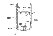
図4に本体ケース10の横断面図を示す。本体ケース10の内部は、縦方向に上下に仕切るベースプレート11を設けている。ベースプレート11により本体ケース10内部が第1の空間SP1と第2の空間SP2に仕切られ、第1の空間SP1、すなわち上方空間にはケーシング部材40が収納され、一方第2の空間SP2、すなわち下方空間には、熱を発生する電気回路ユニット80が収容される。これにより本体ケース10内の例えば保護材や充填材がガス化しても、下方空間に流出することが抑えられる。好ましくは、電気回路ユニット80は密閉空間内に封入する。
(右分割ケース、左分割ケース)
FIG. 4 shows a cross-sectional view of the
(Right split case, left split case)
イオン化装置を構成する本体ケースは、全体として細長い断面逆U字形の形状を有し、上端(図面では下端)は、その断面が比較的滑らかな湾曲形状を有し、この上端からほぼ垂直方向に延びる側壁を有している。また図4に示すように、本体ケース10は長さ方向に沿って第1ケースである右分割ケース10Rと、第2ケースである左分割ケース10Lに2分割されている。右分割ケース10Rは、ベースプレート11の両端から下方(図4において上方)に折曲した垂直壁面12で断面をコ字状に形成して開口すると共に、ベースプレート11の背面の一端から直線状に延長され、先端を折曲させた第1の壁面として第1折曲壁面14を一体に形成している。断面コ字状部分で区画された第1の空間SP1には、後述する高電圧配板50を保持する保持板55をインサート成形したケーシング部材40を収納する。このように高電圧の部材を一体に形成した隔壁で3方から囲むことで、高電圧部材を隔離、絶縁する。
The main body case constituting the ionization device has a generally elongated U-shaped cross section, and the upper end (the lower end in the drawing) has a curved shape with a relatively smooth cross section. It has an extending side wall. Further, as shown in FIG. 4, the
一方、左分割ケース10Lは、図4に示すようにベースプレート11の背面で第1折曲壁面14を設けた側と反対側に当接し、かつ第1折曲壁面14の先端と当接する第2の壁面として第2折曲壁面に形成される。左分割ケース10Lの形状は、垂直壁面12を形成した右分割ケース10Rに応じて、図4に示すように右分割ケース10Rのベースプレート11背面から延長されるように、垂直壁面12の長さ分だけ短く形成する。この左分割ケース10Lと、第1折曲壁面14と、ベースプレート11の背面とにより第2の空間SP2が形成される。第2の空間SP2には、後述する電気回路ユニット80を配置する。電気回路ユニット80は、低電圧の部材を含むため、高電圧配板50との間で高い電位差が生じる。このため、ベースプレート11で空間的に隔離して絶縁を図る。さらに、ベースプレート11で第1の空間SP1を区画することにより、高電圧配板50と電気回路ユニット80との沿面距離を長くすることができ、沿面放電を回避できる。
On the other hand, as shown in FIG. 4, the left divided
ここで、従来の除電装置の分解斜視図を図28〜図31に示す。これらの図において、図28は除電装置を斜め下方から見た分解斜視図、図29は図28の内、右分割ケース部101Rを示す分解斜視図、図30は右分割ケース部101Rを斜め上方から見た分解斜視図、図31はケースの断面図を、それぞれ示している。右分割ケース部101Rと左分割ケース部101Lは断面形状が異なり、図31の断面図に示すように右分割ケース部101Rは断面ヒ字状に形成され、逆し字状の左分割ケース部101Lと係合される。このため右分割ケース部101Rは、図29に示すように、その側壁部分に、横方向つまり水平方向に延びるベースプレート109が、右分割ケース部101Rの全長にわたって一体に形成さている。ベースプレート109の幅方向の自由端つまり側縁には、90度に上方(図29、図30では下方)向けて屈曲した屈曲部110が形成されている。他方、左分割ケース部101Lは、その側壁部分にL字状部分111が形成され、このL字状部分111は、左分割ケース部101Lの全長にわたって延びている。また左右の分割ケース部101L、101Rの上端(図面では下端)はスライド嵌合可能になっている。すなわち、図示のケースでは、右分割ケース部101Rの上端(図面では下端)に、横方向に突出した拡大ヘッド107が形成され、この拡大ヘッド107は、右分割ケース部101Rの上端縁に沿って右分割ケース部101Rの全長にわたって延びている。左分割ケース部101Lの上端(図面では下端)は、その上端(図面では下端)に、拡大ヘッド107の輪郭と相補的な形状を有する溝108が形成され、この溝108は、左分割ケース部101Lの上端縁に沿って長手方向に延びており、溝108の両端は共に開放されている。溝108はそのいずれの端からも拡大ヘッド107を受け入れることができ、例えば溝108の一端側から拡大ヘッド107を挿入して、左右の分割ケース部101L、101Rを、相対的に、その長手方向にスライドさせることにより、左右の分割ケース部101L、101Rは、離脱不能な状態になり、下端(図面では上端)に向けて開放した逆U字状の断面形状を作る。
Here, an exploded perspective view of a conventional static eliminator is shown in FIGS. In these drawings, FIG. 28 is an exploded perspective view of the static eliminator as viewed obliquely from below, FIG. 29 is an exploded perspective view of the right divided
この構造では、右分割ケース部101Rの断面ヒ字状の、T字状部分で強度が補強されるが、一方左分割ケース部101Lとの接合部分が弱くなるという問題があった。そこで本実施の形態では、図4に示すように、右分割ケース10RのT字状を構成するベースプレート11の先端を、さらに屈曲させて上方に突出させた垂直壁面12でコ字状に形成している。右分割ケース10Rの全長にわたって垂直壁面12を形成したベースプレート11を構成することで、ケースの長さ方向全体に渡って更に剛性を増し、ケースの全長を長くしても十分な強度を維持できる。特に本実施の形態では、断面コ字状の背面の一端を延長して逆h状としているため、断面T字状の構造以上の強度を発揮できる。
In this structure, although the strength is reinforced by the T-shaped portion having a cross-section of the right
更に、この構成によって沿面放電の虞も低減できる。すなわち、ベースプレート11によって本体ケース10内部が区画され、図4において上側の第1の空間SP1に高電圧経路VPが配置され、下側の第2の空間SP2には電子回路等が配置される。従来の構成では図31に示すように、ベースプレート109の端縁が左分割ケース部101Lに当接する部分で隙間が生じるため、この隙間から上側の第1の空間SP1に配置された放電回路の高電圧と、下側の第2の空間SP2の低電圧部分との間の放電経路となりうる。特に上側に配置された放電回路の高電圧と、下側部分の低電圧部分との間で大きな電位差が生じるため、沿面距離を十分大きくとならないと沿面放電が生じる虞があった。これに対し本実施の形態では、図4に示すように上側の第1の空間SP1が完全に断面コ字状に区画されて隙間が無くなる結果、沿面放電を生じるには、垂直壁面12を乗り越えて下側部分に侵入する必要があり、沿面放電経路を極めて長くすることで安全性が高められる。
Furthermore, the risk of creeping discharge can be reduced by this configuration. That is, the interior of the
このように、一体に形成された断面コ字状によって長手方向に延長されたイオン化装置の長さ方向における十分な剛性を発揮することができる。さらに、ベースプレートでケーシング体を区画することにより、高電圧が印加されるケーシング体と、低電圧の部分を含む電気回路ユニット80との電位差による沿面放電経路を長くして、沿面放電の発生を回避できる。
Thus, sufficient rigidity in the length direction of the ionizer extended in the longitudinal direction can be exhibited by the integrally formed cross-sectional U-shape. Further, by dividing the casing body with the base plate, the creeping discharge path due to the potential difference between the casing body to which the high voltage is applied and the
加えて、図31に示す従来の除電器では、L字状部分111と屈曲部110が完全に密着していないため、隙間から高電圧配板が放電してしまい、内部の電源回路や制御回路等を破損する可能性があった。これを回避するため、従来は接合部分をテープ等で覆う必要があった。
In addition, in the conventional static eliminator shown in FIG. 31, since the L-shaped
また除電器が長大化すると、長手方向に撓みが生じ、さらにL字状部分111と屈曲部110との密着性が低下して、放電の発生する可能性が更に高まる。さらに撓みが発生すると、電極針と高電圧配板との接点が確保できないといった問題も生じる。さらには、除電対象物との距離が、除電器の支持部分とその中間部分とで異なることになり、最悪の場合には電極針から直接放電が生じる可能性が生じる。
Further, when the static eliminator becomes longer, bending occurs in the longitudinal direction, and the adhesiveness between the L-shaped
これらを防止するためには、除電器の両端部に加えて、中間部分を別途支持する構造を設ける必要が生じる。設置場所に制約がある場合、例えば天井に2カ所しか支持部材を固定する場所が無い場合には、新たに支持部材の固定箇所を設ける必要が生じるといった問題もあった。 In order to prevent these, it is necessary to provide a structure for separately supporting the intermediate portion in addition to the both ends of the static eliminator. When there is a restriction on the installation location, for example, when there are only two places for fixing the support member on the ceiling, there is a problem in that it is necessary to newly provide a fixing location for the support member.
このような問題を解決するためにも、図4に示すようにベースプレート11の端縁から垂直壁面12を延長して断面コ字状部分を一体に形成することにより、ベースプレート11の上下を完全に区画し、沿面距離を長くすると共に剛性を高め、この結果除電装置を長大化させても中間支持部材等の新たな支持部材を必要とせず、安定して使用できるようになった。
(ケーシング部材40)
In order to solve such a problem, as shown in FIG. 4, the
(Casing member 40)
本体ケース10内部のベースプレート11で区画された第1の空間SP1には、ケーシング部材40が配置される。ケーシング部材40は、図3に示すように、10本のケーシング部材40を連結部材60で連結して一のケーシング体41を構成している。ケーシング部材40の斜視図を図5に示す。この図に示すように、各ケーシング部材40は4つの電極針90を備えている。従って図3のイオン化装置100は、計40本の電極針90を有する。このようにイオン化装置100の本体ケース10内部では複数のケーシング部材40を継ぎ足し式で連結し、外側の本体ケース10はケーシング部材40の数に応じた長さに一体物で形成することで、ケーシング部材40同士の連結部分の強度を維持しつつ、本体ケース10内部に配置するケーシング部材40を共通化して電極針数や長さの異なるイオン化装置を容易に構成できる。
A casing
ケーシング部材40は、耐圧性や耐トラッキング性、誘電率等の電気特性の優れた樹脂で構成する。またケーシング部材40の端縁からは、搬送ガス経路GPと連通された内部ガスポート43、及び高電圧ポート44として高電圧配板50が設けられた挿入部57が突出されている。
The casing
図6〜図8に、イオン化装置100の端部近傍の断面図を示す。これらの図において、図6は端部ガスポート22を設けた側、図7は端部ガスポート22と中間ガスポート21を設けた側、図8は、搬送ガス供給用継ぎ手64でケーシング部材40を連結する部分の断面図を、それぞれ示している。一方図9に、電力供給用継ぎ手65でケーシング部材40を連結する部分の断面図を示す。
(内部接続ポート42)
6 to 8 are sectional views of the vicinity of the end of the
(Internal connection port 42)
各ケーシング部材40は、長さ方向に他のケーシング部材40を連結するために、両端面に内部接続ポート42を形成する。内部接続ポート42は、図5〜図7に示すように搬送ガスとして空気を使用した搬送エア用の内部ガスポート43と高電圧経路VP用の高電圧ポート44とを備え、これらを物理的に分離された状態で連結する。これによって、搬送ガス経路GPと高電圧経路VPとが物理的に隔離されるので、両者間の絶縁が確実に保たれる。内部ガスポート43と高電圧ポート44とは、連結部材60の連結ガスポート61と連結高電圧ポート62に各々連結される(後述する図16参照)。特に内部ガスポート43と連結ガスポート61は、Oリング87Aを介して継ぎ手と連結される。Oリングを用いることで気密接続状態が容易に実現でき、連結部分からの絶縁やエア漏れ、これらの干渉等が防止される。
(保持板55)
Each casing
(Holding plate 55)
保持板55は、高電圧配板50を保持する。保持板55の外観を図10に示す。図10(a)は斜め上方から見た斜視図を、図10(b)は斜め下方から見た斜視図を、図10(c)は下ケースにセットして充填樹脂JJで被覆した状態での保持板55を斜め下方から見た斜視図を、それぞれ示している。これらの図に示すように、保持板55は上面で高電圧配板50を表出させ、側面のエッジ部分及び下面(接触片59を設けた部分を除く)を被覆樹脂で被覆している。また保持板55は、挿入先のケーシング部材40の下ケース45と同軸に電極針90をセットするための第1スリーブ56を設けている。図10の例では、保持板55に4つの電極針90を装着可能に構成している。なお、3つ以下、あるいは5つ以下の電極針を装着可能なケーシング部材を構成することも可能である。また、異なる電極数のケーシング部材を混在させてケーシング体を構成することも可能である。また保持板55の端縁では、高電圧配板50の周囲を被覆した挿入部57が形成され、高電圧配板50の端縁に形成された接続端子51は挿入部57から更に突出されている。
The holding
保持板55は、高電圧配板50を保持するに際して、エア経路側、すなわち下面側において、電極組立体92の電極針90が挿入される部分を除き、高電圧配板50がエア経路に表出しないようにするために、高電圧配板50を覆う構造としている。逆にいえば、高電圧配板50はエア経路側で表出しないように被覆すれば足り、上面側、すなわち高電圧経路VP側では表出していても構わない。高電圧配板50のエア経路側では、電極針90が接触する部分のみ、接触片59を設けてエア経路側の表面で露出しており、その露出部分を取り囲むように第1スリーブ56が形成されている。
(下ケース45)
When the holding
(Lower case 45)
ケーシング部材40を構成する下ケース45の外観を図11に示す。図11(a)は斜め上方から見た斜視図、図11(b)は斜め下方から見た斜視図を、それぞれ示している。この下ケース45は、略平行に離間した2つの側壁と、これに連続する2つの端壁と、底壁とを有する上方を開口した矩形形状の箱形に形成される。下ケース開口部46側には、保持板55が挿入される。保持板55は、上下にリブを設けており、また下ケース開口部46に挿入できる大きさ及び形状に形成される。図12に、下ケース開口部46にセットされた保持板55を樹脂で被覆したケーシング部材40の断面図を示す。この例では、下ケース開口部46は、下方の内径を保持板55の幅よりも狭く形成し、開口部の端縁に段差部47を設けて、保持板55を段差部47で支持して閉塞できるよう設計されている。
An appearance of the
下ケース開口部46を保持板55で閉塞することで、直線状の搬送ガス経路GPを構成する密閉空間が形成される。これにより、図4、図15(電力供給用継ぎ手65の断面図)等に示すように、保持板55の下面と電極組立体92(後述)の間で、ガス経路の一部を構成する搬送ガス経路GPが構成される。
By closing the lower case opening 46 with the holding
下ケース45は、その底壁に、保持板55に設けられた比較的短い第1スリーブ56と同軸の比較的長い円筒状の第2スリーブ48を備えている。この第2スリーブ48は、下ケース45の底壁から下方に延び、その両端を開放している。すなわち、第2スリーブ48は上下に延びる貫通孔を構成しており、この第2スリーブ48は第1スリーブ56よりも大きな径を有しているのが好ましい。第2スリーブ48の外周面には、第2スリーブ48の基端部分に、沿面距離を拡大するための2つの円周フランジ49が形成されている。
(高電圧配板50)
The
(High voltage board 50)
高電圧配板50はケーシング部材40と同様に長手方向に延長された板状に形成され、導電性に優れた物質で構成される。例えばステンレス鋼等で高電圧配板50を形成することで、導電性を維持しつつイオン化装置の長さ方向について補強板の役目を果たし、剛性を向上させることができる。この高電圧配板50は、電力供給用継ぎ手65を介して電気回路ユニット80を構成する正側昇圧回路83Aと、負側昇圧回路83Bに接続されている。この高電圧配板50は、保持板55の一端から他端まで直線状に延長された形状を有している。また、高電圧配板50の一端は、電気回路ユニット80からの高電圧エネルギを受け入れる接続端子51を構成しており、接続端子51を保持板55の端面で突出させて電力供給用継ぎ手65に電気接続される。
(接続端子51)
The high
(Connection terminal 51)
接続端子51は、ケーシング部材40の両端から突出される挿入部57から更に突出されている。図13に、電力供給用継ぎ手65でケーシング部材40同士を接続する部分の拡大図を示す。この図に示すように、接続端子51は湾曲されて略U字状に折り返されてU字片を形成している。またU字片は、図14(標準継ぎ手63の縦断面図)に示すように二股に分岐させている。これにより、後述する電極連結パイプ67内部の曲面に応じて、二股の各U字片が各々弾性変形して当接し易くできる。
The
高電圧配板50は、インサート成型によって保持板55に一体的に介装される。これにより高電圧配板50は保持板55に確実に固定され、不要な部分を本体ケース10内部に露出させず、沿面経路を排除できる。保持板55は、樹脂成形材料等で構成され、図10(a)に示すように上方を開口した有底の枠状に形成し、この枠状の上面に高電圧配板50が表出するようにインサート成型している。また枠状の開口は、高電圧配板50の形状にほぼ沿うように細長い矩形状に形成される。さらに枠状の開口面積は高電圧配板50よりも多少小さくすることで、高電圧配板50の周囲を保持板55で覆い、エッジ部分を確実に被覆して無用な放電を回避する。上面に表出された高電圧配板50は、後述するように固定プレート54で被覆される。この高電圧配板50は、端部の接続端子51を表出させつつ、図6、図15等に示すように端部近傍を折曲しており、折曲部分から先端に向かって被覆樹脂で被覆して保持板55端部の挿入部57を形成している。このように折曲部分を形成し、折曲部分の周囲を被覆被覆で被覆することにより、この部分で高電圧配板50と被覆樹脂との接合性を高めることができる。
The high
さらに図10(b)に示すように、保持板55の下面も枠状に形成し、枠状の中間に第1スリーブ56を設けると共に、第1スリーブ56の無い部分にはリブ58を渡して補強している。保持板55の下面では、第1スリーブ56の部分を除いて高電圧配板50が表出しないよう完全に覆い、沿面経路の形成を阻止している。一方、第1スリーブ56の部分では、円筒形の第1スリーブ56の底面に高電圧配板50を表出させ、電極針90との接触片59を構成している。
(接触片59)
Further, as shown in FIG. 10B, the lower surface of the holding
(Contact piece 59)
高電圧配板50には、保持板55の第1スリーブ56に対応する部分に、電極針90と電気接続するための接触片59が設けられている。接触片59は図10(b)に示すように一対の接触面を対向させており、この間に電極針90の上端面を挿入して狭持する。接触片59の先端は、湾曲させて接触面同士の間隔を狭くするようにし、この間で弾性的に電極針90を保持して確実に電気接続を得る。接触片59は好ましくは高電圧配板50と同じ部材で構成し、例えばステンレス板をコ字状に接触して高電圧配板50と固定する。あるいは、高電圧配板を切り起こして接触片を設けてもよい。
(樹脂2段階充填)
The high
(Resin 2-stage filling)
図12に示すケーシング部材40の横断面図から明らかなように、高電圧配板50は被覆樹脂HJと充填樹脂JJで被覆されている。従来、高電圧配板のエッジ部分が表出して放電を生じさせないよう、樹脂などで被覆することが行われていた。図32に、従来の高電圧配板を被覆する構成を示す。図32(a)においては、主エア通路S1と高電圧経路S3とを分離するために、固定プレート257と支持プレート225とで高電圧配板258を狭持した状態で、図32(a)に示すAの部分で超音波溶着で接着した後、さらにこの支持プレート225とボックス状部材とをBの部分で超音波溶着等で気密に連結していた。この構成では、4つの部材を組み立てる必要があり、特に超音波溶着等の工程に手間がかかり、組み立てコストがかかるという問題があった。
As is apparent from the cross-sectional view of the
一方、図32(b)に示す構成では、予め高電圧配板258を保持板55にインサート成型すると共に、保持板55とケーシング部材40とをOリング286で気密に連結することによって、主エア通路S1と高電圧経路S3とを隔離している。この構成によれば、超音波溶着作業を不要にできる上、リブや溝等の超音波溶着代も不要にできる。しかしながらこの方法では、Oリング286を使用して主エア通路S1を気密に封止していたため、Oリング286の面積分だけ通路が狭くなるという問題があった。
On the other hand, in the configuration shown in FIG. 32 (b), the high
これに対し本実施の形態では、図12に示すように先ず高電圧配板50の上面(図12において下面)を表出させ、側面のエッジ部分及び下面(接触片59を設けた部分を除く)を被覆樹脂HJで被覆した保持板55を形成する。保持板55の樹脂形成は、インサート成形により行われる。またトランスファー成形や射出成形を利用することもできる。
On the other hand, in this embodiment, as shown in FIG. 12, first, the upper surface (the lower surface in FIG. 12) of the high-
次いで、この保持板55を図11に示す下ケース45に挿入する。下ケース45は断面をほぼコ字状として上方を開口しており、この下ケース開口部46がケーシング部材40内の搬送ガス経路GPを構成する。下ケース開口部46に保持板55を挿入し、段差部47で保持板55を支持して下ケース開口部46を閉塞し、内部空間を搬送ガス経路GPとする。この際、保持板55は高電圧配板50の表出面が上方を向く姿勢で下ケース開口部46に挿入される。この状態で下ケース開口部46にさらに充填樹脂JJを充填して固定プレート54を形成し、高電圧配板50の表出面を含め、保持板55を固定プレート54で完全に下ケース45に埋設する。被覆樹脂HJを充填樹脂JJと同じ材質とすることで、2段階の樹脂成形によっても界面で強固に固定され、保持板55と下ケース45を一体としたケーシング部材40を形成できる。
Next, the holding
下ケース45の側面には、図12に示すように保持板55を下ケース開口部46にセットした状態で外部に連通したスリット53を形成している。これにより、2回目の樹脂成型の際に充填樹脂JJがスリット53に充填された状態で固化して突起57bを形成し、固定プレート54は下ケース開口部46で確実に固定される。
On the side surface of the
この方法であれば、高電圧配板50の周囲を完全に被覆することができ、空気の介在による放電が効果的に阻止され、また樹脂中に埋没させたことで沿面放電経路も形成されない。加えて、高電圧配板50の下ケース45への固定も同時に行えるので、超音波溶着などの接着工程が不要で組み立ての作業性を改善できる。また超音波溶着代を設ける必要もないので、一層の小型化が実現できる。また超音波溶着によるダスト発生からもフリーで、さらにOリングなどによる気密封止も不要である。加えて、2回目の樹脂成型の際には図12に示すように、保持板55が下ケース開口部46の段差部47で保持されて閉塞されるため、充填樹脂JJが搬送ガス経路GPに流入することもなく、また樹脂成型時の圧力で搬送ガス経路GPが狭められることもない。
With this method, the periphery of the high-
なお、これらの樹脂による被覆は、高電圧配板50の端縁を除く部分で行う。すなわち、ケーシング部材40の完成体において、電気接続のための高電圧配板50の接続端子51は図5に示すように突出させている。
(連結部材60)
In addition, the coating with these resins is performed at a portion excluding the edge of the high
(Connecting member 60)
ケーシング部材40同士の連結には、連結部材60が使用される。図6〜図9、図13及び図16に示すように、連結部材60はケーシング部材40のガスポート43を連結する連結ガスポート61及び高電圧ポート44を連結する連結高電圧ポート62を備える。2つのケーシング部材40の間に連結部材60を配置して、連結部材60の両側からケーシング部材40を挿入し、これらケーシング部材40のガスポート43及び高電圧ポート44同士が連通される。本実施の形態では、連結部材60として本体ケース10の長手方向に沿ってケーシング部材40を挿抜して連結する継ぎ手を使用している。これにより、ケーシング部材40の長手方向の寸法誤差を、継ぎ手への挿入量により調整することが可能となる。
A connecting
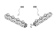
従来のイオン化装置では、図33に示すように、ケーシング部材40B同士を直接連結していたため、ケーシング部材40Bを連結したケーシング体の全長が固定される。このため、ケーシング体を収納する本体ケースとの寸法誤差によって、がたつきが生じたり収納できない事態が生じる虞があった。特に多数のケーシング部材40Bを連結する構造では、寸法誤差が累積されて大きさの不一致が生じやすくなる。これに対し、本実施の形態では連結部材60を介在させ、連結部材60へのケーシング部材40の挿入量を調整可能とすることで、このような寸法誤差の調整を可能としている。
In the conventional ionization apparatus, as shown in FIG. 33, since the
連結高電圧ポート62及び連結ガスポート61は、図13、図16等に示すように電極針からイオンの放出される方向に対して、連結高電圧ポート62、連結ガスポート61の順で形成される。この配置によって、ケーシング部材40の高電圧経路VP、搬送ガス経路GPの配置と一致させ、ケーシング体41内部でほぼ直線状に各経路を挿通させることができる。また、連結高電圧ポート62及び連結ガスポート61は、一体に形成することが好ましい。これにより、各ポートを容易かつ安価に形成すると共に、連結部材の強度を高めてイオン化装置の剛性向上に寄与できる。
(継ぎ手)
The connected
(Joint)
本実施の形態では、連結部材60を構成する継ぎ手として、標準継ぎ手63の他、中間搬送ガス配管71を接続するための搬送ガス供給用継ぎ手64、電気回路ユニット80で生成される高電圧をケーシング部材40の高電圧配板50と接続するための電力供給用継ぎ手65の3種類を使用している。図16に標準継ぎ手63、図17に電力供給用継ぎ手65、図18に搬送ガス供給用継ぎ手64を、それぞれ示す。また図14は標準継ぎ手63、図15は電力供給用継ぎ手65の接続部分の断面図を示している。
In this embodiment, as a joint constituting the connecting
各継ぎ手は、図6〜図9、図16に示すように搬送ガスを通す連結ガスポート61と、高電圧配板50同士を連結するための連結高電圧ポート62とを個別に設けている。図16に示す例では、下方(図16において上方)に中空円筒状の連結ガスポート61、上方にこれよりも小さい、連結高電圧ポート62を開口している。これらは貫通口であって、いずれの開口面からもケーシング部材40を挿入可能としている。
As shown in FIGS. 6 to 9 and 16, each joint is individually provided with a
連結ガスポート61は、搬送ガスを各電極針90に搬送するために内面を面取りして曲面状としており、ガス流がスムーズに流れるようにしている。この例では十分な搬送ガスを搬送できるよう、連結高電圧ポート62よりも開口面積を大きくしている。連結ガスポート61同士の接続には、従来は図28、図29に示すようにゴム管などの可撓性チューブ135が利用されていたが、本実施の形態においては剛性の高い継ぎ手で構成することで、連結部分においても剛性向上に寄与できる。また連結高電圧ポート62にケーシング部材40の内部ガスポート43を接続する接続部分でガス漏れを生じないよう、気密に接続する。図15の例では、内部ガスポート43の外周にOリング66を配置し、シーリングしている。
(電極連結パイプ67)
The connecting
(Electrode connection pipe 67)
連結高電圧ポート62は、開口端をほぼ矩形状にしてケーシング部材40の挿入部57を挿入可能な大きさ及び形状に形成される。また連結高電圧ポート62の内部には、図13〜図15に示すように、矩形状開口端よりも小径の、中空円筒状の電極連結パイプ67を設けている。電極連結パイプ67は導電性に優れた物質で構成され、円筒内面で高電圧配板50の端縁に形成された接続端子51であるU字片(後述)を当接させて電気的に接続する。また継ぎ手は、電極連結パイプ67をインサート成型等により連結高電圧ポート62内部に開口部分を一致させて埋設している。なお電極連結パイプ67は、中空状の開口を有すればよく、内面及び外観を円筒状にする必要はなく、例えば矩形状とすることもできる。例えば外形をブロック状とすることで電極連結パイプ67の設置を容易にできるので、ブロック状の金属に貫通孔を設けた電極連結パイプ67を使用できる。一方、電極連結パイプ67の内面を円筒状とすることで、エッジを低減して放電の虞を一層低減できる。
The connection
電極連結パイプ67には、ケーシング部材40の端縁から突出した接続端子51が挿入される。上述の通り、接続端子51は略U字状に折り返されてU字片を形成しており、図13、図15に示すように接続端子51の底面及びU字片の折り返し部分の2カ所で、電極連結パイプ67内面に当接して電気的に接続している。このように接続端子51同士をエッジ面で直接対向させず、R状に折曲させた状態で対向させることでエッジ部分を低減して無用な放電を防止できる。またこの例では、対向するU字片の背面同士は意図的に離間させることで、この部分の接触不良を回避し、より確実な接触が得られる電極連結パイプ67内面との導通を利用している。特に接続端子51のU字片は、図14に示すように二股に分岐させているため、電極連結パイプ67内部の曲面に応じて、二股の各U字片が各々弾性変形して確実に当接し、接触不良を解消できる。
(搬送ガス供給用継ぎ手64)
A
(Carrier gas supply joint 64)
標準継ぎ手63は、上述の通り隣接するケーシング部材40同士を接続し、搬送ガス経路GPと高電圧経路VPとを接続する。一方、搬送ガス供給用継ぎ手64は、図3、図8に示すように本体ケース10の中間で、ケーシング部材40同士を接続すると共に、この位置から両端に接続されたケーシング部材40に対し搬送ガスを供給する。これにより、搬送ガスは搬送ガス供給用継ぎ手64を介してケーシング体41の両端及び中間から供給される。
As described above, the standard joint 63 connects the
従来のバータイプのイオン化装置では、長手方向に延長すると、両端から供給される搬送ガスが中央の電極針まで搬送され難くなり、ガス圧が低下して十分なイオンの飛翔が得られない、あるいは電極針の位置毎にイオンの飛翔距離が異なり除電効果が不均一になるといった問題があった。これに対し本実施の形態では、中央近傍のケーシング部材40に対して、継ぎ手を介して搬送ガスを直接供給できるので、バータイプのイオン化装置を長手方向に延長しても搬送ガス不足、不均一の問題を解消できる。特に、搬送ガスを供給するための専用の部材を設けることなく、継ぎ手に搬送ガス供給機構を付加することで、継ぎ手を変更するのみで所望の位置に搬送ガスを供給できるようになり、構成の簡素化や組み立て作業の向上面にも寄与する。図3に示す例では、10本のケーシング部材40を連結したケーシング体41を収納する全長3mのイオン化装置100の中心である端面から1.5mの位置、すなわち端部から数えて5本目のケーシング部材40と6本目のケーシング部材40とを接続する継ぎ手に、搬送ガス供給用継ぎ手64を用いている。なお本明細書において中間に位置するケーシング部材40とは、ケーシング体41を構成する複数のケーシング部材40の内、端部に位置するケーシング部材40を除くという意味である。
In the conventional bar-type ionization apparatus, if it is extended in the longitudinal direction, the carrier gas supplied from both ends becomes difficult to be transported to the central electrode needle, and the gas pressure is lowered so that sufficient ion flight cannot be obtained, or There is a problem in that the ion flight effect varies depending on the position of the electrode needle, and the charge removal effect becomes non-uniform. In contrast, in the present embodiment, since the carrier gas can be directly supplied to the
図19に、図18の搬送ガス供給用継ぎ手64のA−A線における断面図を示す。搬送ガス供給用継ぎ手64は、図18の斜視図及び図19の断面図に示すように、搬送ガス経路GP及び高電圧経路VPを隔離して形成すると共に、図において下方に搬送ガス供給口68を開口している。搬送ガス供給口68は、図19の断面図に示すように搬送ガス経路GPと連通している。この際、搬送ガス供給口68と搬送ガス経路GPの間に位置する高電圧経路VPで搬送ガス流を阻害されないように、搬送ガス供給口68の内部で高電圧経路VPの下面から下方に向かって搬送ガス案内片69が延長されている。搬送ガス案内片69は、搬送ガス供給口68から突出し、先端に向かって先細りとなるようテーパ状に形成される。これによって、図19の断面図において下方から供給される搬送ガス流が、テーパ状の搬送ガス案内片69で二分されて搬送ガス経路GPに導入される。これにより、高電圧経路VPが障害となって乱流が生じることを解消し、圧力損失を低減してスムーズに搬送ガスを搬送ガス経路GPに導入して、搬送ガス経路GPに連通された各電極針90の周囲から放出される。
FIG. 19 is a cross-sectional view taken along line AA of the carrier
搬送ガス供給口68には、中間搬送ガス配管71を接続するための搬送ガス供給用接続部材として、搬送ガスバルブ70が接続される。搬送ガスバルブ70は、連結ガスポート61と挿通されており、図3に示すように中間搬送ガス配管71と接続することで、連結ガスポート61を介して搬送ガス経路GPと挿通される。中間搬送ガス配管71は、本体ケース10内部の第2の空間SP2に配置され、図7に示すサイドカバー20に設けられた中間ガスポート21に接続される。図20に、搬送ガスの配管と搬送ガスが搬送される経路を示す。このように、一方のサイドカバー20には端部ガスポート22が、他方のサイドカバー20には端部ガスポート22に加えて中間ガスポート21が設けられる。搬送ガスは、外部接続されるエア供給ユニットからケーブルを介して搬送される。ケーブルと連結ポートの接合部分、すなわち端部ガスポート22及び中間ガスポート21は、Oリング等を用いて気密に連結される。端部ガスポート22及び中間ガスポート21を介して、外部から空気等の搬送ガスが供給され、イオン化装置の両端及び中間から、搬送ガスが搬送ガス経路GPに導入される。これにより、中間のケーシング部材40にも安定して搬送ガスが供給される。
A
また、搬送ガスの圧力を端部ガスポート22と中間ガスポート21で調整することもできる。例えば、中間ガスポート21から導入される搬送ガスは、配管経路が長く圧力損失が生じることを考慮して、圧力を若干高く設定してもよい。あるいはパイプ径を変更して流速を速めることもできる。
Further, the pressure of the carrier gas can be adjusted by the
中間搬送ガス配管71は、硬質の樹脂製パイプなどが利用できる。本体ケース10の長手方向に沿って中央付近まで硬質製の中間搬送ガス配管71で配管することでも、長さ方向の剛性の向上に寄与できる。さらに中間搬送ガス配管71の周囲を、図2に示すように補強部材72で保護する。補強部材72は断面をコ字状として、コ字状の開口部分に中間搬送ガス配管71を挿入してこれを保護すると共に、長さ方向に一体の樹脂等押し出し材で成型した硬質材とすることで、本体ケース10の更なる剛性の向上に資する。図2の例では、補強部材72は図において本体ケース10の右端面から中間搬送ガス配管71を設けた中央部分のみならず、さらに延長して昇圧ユニット83付近まで配置される。このように、本体ケース10内のデッドスペースに補強部材72を挿入して、剛性の向上を図ることができる。
(電力供給用継ぎ手65)
The intermediate
(Power supply joint 65)
電力供給用継ぎ手65は、図9、図17に示すように本体ケース10の中間で、ケーシング部材40同士を接続すると共に、電気回路ユニット80で生成される高電圧を高電圧配板50に供給するための電圧入力部となる。このため電力供給用継ぎ手65は、電気回路ユニット80の出力端子と、ケーシング部材に含まれる高電圧配板とを連結高電圧ポートを介して接続するための電力供給用接続部材65bを備える。これにより、電気回路ユニット80で生成された高電圧をケーシング部材40の高電圧配板50に供給するための配線や別部材を別途用意することなく、一の継ぎ手でケーシング部材40同士の連結と、高電圧の供給とを実現でき、構成の簡素化及び組み立て工程の省力化が図られる。
(電気回路ユニット80)
As shown in FIGS. 9 and 17, the power supply joint 65 connects the
(Electric circuit unit 80)
電気回路ユニット80は電極針90に印加する高電圧を生成するための回路である。なお本明細書において高電圧とは、±2kV〜7kVの電位差を備えることを指す。この電位差は、高すぎると除電器内部で絶縁破壊を起こしたり、ワークに放電してしまうことがあり、一方低すぎると除電できなくなることがあるので、適宜適切な範囲に設定される。電気回路ユニット80は、電源ユニット81と、制御ユニット82と、昇圧ユニット83を含む。電源ユニット81は、外部電源と接続されて電力を受ける電源回路を備える。制御ユニット82は電源ユニット81で受けた電力で駆動され、各電極針90の動作を制御する制御回路を備える。昇圧ユニット83は、電源回路で受けた電圧を昇圧して、高電圧を生成する昇圧回路を備える。図2の例では、正の高電圧を生成する正側昇圧回路83Aと、負の高電圧を生成する負側昇圧回路83Bを有する。またこれらの正側昇圧回路83A、負側昇圧回路83Bの間に電力供給用継ぎ手65が位置するよう配置され、これによって図17に示すように電力供給用継ぎ手65の両側から正負の高電圧が切り替えて供給され、ケーシング部材40の高電圧配板50に供給される。このため電力供給用継ぎ手65は正負の高電圧を切り替え可能な電子リレーを内蔵することもできる。
The
これらの基板は、図2に示すように各々ユニット状に構成される。このように基板を機能、用途別に纏めて、複数の基板に分割することで各基板を小型化でき、省スペースでの配置が容易となる。図2の例では、本体ケース10の第2の空間SP2内に、ユニット状の電源ユニット81、制御ユニット82、昇圧ユニット83を配置しており、本体ケース10内部の限られたスペースに効率よく収納できる。電源ユニット81を含めた電気回路ユニット80は本体ケース10内部の長手方向において端部に位置させることが好ましい。これによりモーメントを多少向上させてバランス良く配置でき、さらにデッドスペースを排することができる。また、一方の端部に電気回路ユニット80を配置し、他方の端部、すなわち中間ガスポート21を備えたサイドカバー20からは中間搬送ガス配管71を配置することで、本体ケース10内のスペースを効率よく利用できる。加えて、中間ガスポート21を備えたサイドカバー20側から補強部材72を延長して、電気回路ユニット80の配置されていないデッドスペースを補強部材72で埋めて、可能な限りの剛性向上を図ることができる。
These substrates are each configured in a unit form as shown in FIG. As described above, the substrates are grouped according to function and application and divided into a plurality of substrates, whereby each substrate can be miniaturized, and space-saving arrangement becomes easy. In the example of FIG. 2, the unit-shaped
本体ケース10内部で保持板55の上方の空間の空間を利用し、ここにユニット状として配置しやすくした電気回路部材を配置することで、必要な部材を本体ケース10内に効率よく組み込むことができる。また漏電対策のため、高圧電源回路等を組み込んだ制御ユニット82を構成後、シリコーン樹脂等の充填材で充填することもできる。
(電極針90)
By using the space above the holding
(Electrode needle 90)
図21に、イオン化装置の電極針90を設けた部分の断面図を示す。電極針90は、これを保護するための保護部材91と一体化されて電極組立体92を構成し、この電極組立体92は、ケーシング部材40の第2スリーブ48及び保持板55の第1スリーブ56によって着脱自在に保持される。そして、ケーシング部材40に取り付けられた電極組立体92は、ケーシング部材40から下方に向けて垂下し、電極組立体92の下端部分が対向電極プレートであるカバー部30から外部に露出した状態になる。
(電極組立体92)
FIG. 21 shows a cross-sectional view of a portion where the
(Electrode assembly 92)
電極組立体92の電極針90は、例えばタングステン等から作られており、電極針90は、その先端部及び後端部つまり上端部とを除いた本体部分が、保護部材91によって被覆されている。保護部材91は、電極針90に沿って延びる小径内筒部分93と、小径内筒部分93の下端つまり電極針90の先端部分から径方向外方に広がる円形部分94と、円形部分94の外周縁から上方向に延びる大径外筒部分95とを有する。大径外筒部分95は、円形部分94から上方に延びて、第2スリーブ48の外周面に沿ってこの第2スリーブ48の基端部分まで延び、上端には沿面距離を拡大するためにフランジ96が形成されている。
The
電極組立体92をケーシング部材40に装着すると、各電極針90が位置決めされると共に、ケーシング部材40の第2スリーブ48の内周面と、保護部材91の小径内筒部分93の外周面とで、ケーシング部材40の搬送ガス経路GPに連なり且つ搬送ガス経路GPに直交して下方に延びる各電極針90毎の円筒状分岐エア通路97が形成され、この円筒状分岐エア通路97は、電極針90の周囲面に沿って形成された貫通孔98を通じて外部と連通している。すなわち、ケーシング部材40内の搬送ガス経路GPを通るエアは、本体ケース10の長手方向に沿って横方向に延びる搬送ガス経路GPに直交して分岐した各円筒状分岐エア通路97及び貫通孔98を通って、各々の電極針90の先端の回りから外部に吐出される。
When the
電極組立体92をケーシング部材40に装着するに際し、ケーシング部材40の第2スリーブ48の外周面には図5に示すように突起52を設け、一方電極組立体92の大径外筒部分95には、図21に示すように突起52を受け入れる斜行スリット99を設けることが好ましい。突起52を斜行スリット99の中に入れた状態で電極組立体92を押し込むことで、電極組立体92及び電極針90を位置決めしつつ、ケーシング部材40に組み付けることができる。
When the
以上の構成により、電極組立体92をケーシング部材40に装着すると、高電圧配板50の接触片59は、電極針90の上端面と圧接して導通状態になる。この電極針90と接触片59との接触部分を含む領域は、保持板55の第1スリーブ56の中に電極組立体92の小径内筒部分93の先端部分が嵌入することにより、ケーシング部材40の搬送ガス経路GP及び円筒状分岐エア通路97と連通された空間を形成する。
With the above configuration, when the
電極組立体92は電極針90を保持しており、電極針90の後端部は電極組立体92の後端部より突出して高電圧配板50と接触している。一方で搬送ガスは、搬送ガス経路GPから円筒状分岐エア通路97、貫通孔98を通じて、電極針90先端が配置されている電極組立体92の先端部に送出され、ここから外部へ放出される。
The
なお、搬送ガスを放出するエア放出口は、電極針90を小径内筒部分で密閉して、その周囲に開口した貫通孔からエアを放出することもできる。この場合、電極針90の先端部が外気に触れる部分とは個別に貫通孔を形成し、電極針90の先端部を中心とする直径状に離間した位置に貫通孔を設ける。ただ、この例に限られず、電極針の周囲を密閉せず、電極針に沿って搬送ガスを送出する構成とすることもできる。
The air discharge port for discharging the carrier gas can also seal the
電極針90はタングステンで構成される。電極針90は使用と共に摩耗し、摩耗した微細な粉末が空中に飛散される。しかしながら、イオン化装置をシリコンウェハなどを製造するクリーンルームで使用する際、シリコンウェハ上にタングステン等の異質の微細粒子が付着することは、ウェハの特性上好ましくない。そこで、電極針をシリコン製とすることで、摩耗して飛散したとしても、シリコンウェハに対してシリコン粒子という同質の物質とすることで、このような問題を解消できる。ただ、シリコン製の電極針は、堅い反面、脆いという問題がある。このため電極針を電極組立体に固定する際に破損するおそれがある。これを回避するために、電極針の先端をシリコン製とし、後端の電極組立体と固定する部分をステンレス製として、これらを電気的に接続することで、コロナ放電にはシリコン製の電極針を使用しつつ、固定にはステンレス製の電極針を利用することができる。
(ブロック図)
The
(Block Diagram)
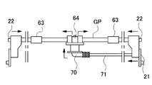
制御回路を含む制御ユニット82は、イオン化装置本体に内蔵されている。イオン化装置の制御回路を図22のブロック図に示す。図22は、イオン化装置の制御回路の概要を示すものである。イオン化装置は、同一の電極針90からプラスイオンとマイナスイオンとが交互に発生するパルスAC式イオン発生方式を採用している。イオン化装置は、プラス側高電圧発生回路160とマイナス側高電圧発生回路161とを有し、これらの高電圧発生回路160、161で電源ユニット81が構成されており、この電源ユニット81は密閉ボックスの中に収容されている。プラス側高電圧発生回路160とマイナス側高電圧発生回路161は、共に、トランス162、163の一次側コイルに接続された自励発振回路164、165と、二次側コイルに接続された、例えば倍整流回路からなる昇圧回路166、167とを含む。高電圧発生回路160、161と電極針90との間には保護抵抗つまり第1抵抗R1が設けられている。トランス162、163の二次コイルの接地端GNDと、フィールドグランドFGとの間には、第2抵抗R2と第3抵抗R3とが直列に接続され、また、対向電極プレートを構成するカバー部30とフィールドグランドFGとの間には、第4抵抗R4と上述した第3抵抗R3とが直列に接続されている。
A
第4抵抗R4を流れる電流をイオン電流検知回路168で検出することにより、電極針90の近傍のイオンバランスを知ることができる。また第3抵抗R3を流れる電流をイオン電流検知回路168で検出することにより、ワークの近傍のイオンバランスを知ることができる。さらに第2抵抗R2を流れる電流を異常放電電流検知回路169で検出することで、電極針90と対向電極プレートを構成するカバー部30又はフィールドグランドFGとの間の異常放電を検出することができ、CPU114で異常放電と判別したときには、アラーム手段である表示LED170を点灯する等して操作者に異常を知らせることができる。またこの例では、プラス側高電圧発生回路160とマイナス側高電圧発生回路161の一方の電圧値を固定し、他方を可変としているが、両方を可変にしてもよい。
By detecting the current flowing through the fourth resistor R4 by the ion
以上、パルスAC式イオン化装置の回路を説明したが、イオン化装置の給電は、ACであってもDCであってもよい。例えば、プラスイオンとマイナスイオンが同時に発生するSSDC式であってもよく、プラスイオンとマイナスイオンとが交互に発生するパルスDC式であってもよい。 Although the circuit of the pulse AC ionizer has been described above, the ionizer may be supplied with power by either AC or DC. For example, an SSDC type in which positive ions and negative ions are generated simultaneously, or a pulse DC type in which positive ions and negative ions are generated alternately may be used.
さらにイオン化装置同士を、ケーブルなどを介して複数本を連結して使用することもできる。サイドカバー20には、他のイオン化装置と連結するための連結ポートが設けられており、連結ポートにケーブルなどを介して他のイオン化装置を接続し、複数のイオン化装置を同期させて使用することもできる。この場合、制御ユニット82は、複数のイオン化装置が接続されたことを検出して、これらを連動して制御できる。また連結されるイオン化装置は、同じタイプのものとする他、長さの異なるもの、電極針の数が異なるもの等、異なるタイプのイオン化装置を連結することもできる。
Further, a plurality of ionizers can be used by connecting them via a cable or the like. The side cover 20 is provided with a connection port for connecting to another ionization device, and the other ionization device is connected to the connection port via a cable or the like, and a plurality of ionization devices are used in synchronization. You can also. In this case, the
以上のイオン化装置は、コントローラとして制御ユニット82を内蔵する構成を採用したが、制御ユニットを外付けとする構成としてもよい。すなわち、制御ユニットを内蔵するコントローラをイオン化装置とは別部材の外部ユニットとして構成し、ケーブルによって接続する形態としてもよい。
The above ionization apparatus employs a configuration in which the
このイオン化装置100は、電源ユニット81で発生された高電圧を高電圧配板50を介してイオン化装置100の各電極針90に供給し、コロナ放電によって空気をイオン化して針先端から放出する。またこのイオン化装置100は、電極針90で発生されるイオンを遠方まで運ぶため搬送ガスを電極針90の周囲から放出する。搬送ガスを各電極針90の周囲から外部に放出することで、電極針90の先端回りでイオン化したエアが除電対象物(ワーク)に向けて下方に強制的に送り込まれ、ワークを除電する。このようにイオン化装置は、エアを利用したダウンフロー機構によって、イオンを確実に送出して除電性能を発揮できる。
The
本発明のイオン化装置は、空気中の静電気制御又は帯電したワークの除電を行うイオナイザ等の除電器として好適に適用できる。 The ionization apparatus of the present invention can be suitably applied as a static eliminator such as an ionizer for controlling static electricity in air or neutralizing a charged workpiece.
100…イオン化装置
1…放電電極;2…高圧電源部;2A…高圧トランス;3…カップリングコンデンサ
10…本体ケース;10R…右分割ケース;10L…左分割ケース
11…ベースプレート;12…垂直壁面;14…第1折曲壁面
20…サイドカバー;21…中間ガスポート;22…端部ガスポート
30…カバー部;31…開口部;32…折り返し片
40、40B…ケーシング部材;41…ケーシング体;42…内部接続ポート
43…内部ガスポート;44…高電圧ポート;45…下ケース;46…下ケース開口部
47…段差部;48…第2スリーブ;49…円周フランジ
50…高電圧配板;51…接続端子;52…突起;53…スリット;54…固定プレート
55…保持板;56…第1スリーブ;57…挿入部;57b…突起;58…リブ
59…接触片
60…連結部材;61…連結ガスポート;62…連結高電圧ポート
63…標準継ぎ手;64…搬送ガス供給用継ぎ手
65…電力供給用継ぎ手;65b…電力供給用接続部材;66…Oリング
67…電極連結パイプ;68…搬送ガス供給口;69…搬送ガス案内片
70…搬送ガスバルブ;71…中間搬送ガス配管;72…補強部材
80…電気回路ユニット;81…電源ユニット;82…制御ユニット
83…昇圧ユニット;83A…正側昇圧回路;83B…負側昇圧回路;87A…Oリング
90…電極針;91…保護部材;92…電極組立体;93…小径内筒部分
94…円形部分;95…大径外筒部分;96…フランジ
97…円筒状分岐エア通路;98…貫通孔;99…斜行スリット
101L…左分割ケース部;101R…右分割ケース部
107…拡大ヘッド;108…溝;109…ベースプレート
110…屈曲部;111…L字状部分;114…CPU;135…可撓性チューブ
160…プラス側高電圧発生回路;161…マイナス側高電圧発生回路
162、163…トランス;164、165…自励発振回路;166、167…昇圧回路
168…イオン電流検知回路;169…異常放電電流検知回路;170…表示LED
200…放電電極バー
210…本体ケース;211…エア供給ユニット;212…電極針
213…高電圧ユニット;225…支持プレート;229…第1スリーブ
236…電極組立体;240…小径内筒部分;245…円筒状分岐エア通路
258…高電圧配板;257…固定プレート;259…切り起こし接触片
286…Oリング
SP1…第1の空間;SP2…第2の空間
GP…搬送ガス経路;VP…高電圧経路;HJ…被覆樹脂;JJ…充填樹脂
S1…主エア通路;S2…密閉空間;S3…高電圧経路
DESCRIPTION OF
DESCRIPTION OF
Claims (10)
前記電極針に高電圧を印加するための電気回路ユニットと、
細長形状のユニット状に構成され、前記電気回路ユニットから電力供給を受けるための高電圧配板を備えると共に、前記複数の電極針を離間させて装着可能で、前記高電圧配板を介して前記電気回路ユニットから供給された高電圧を各々の電極針に印加するケーシング部材と、
複数のケーシング部材を長手方向に機械的に連結すると共に、各ケーシング部材の高電圧配板同士を電気的に接続するための連結部材と、
前記連結部材で複数のケーシング部材を連結させたケーシング体及び前記電気回路ユニットを内部に収納する細長形状の本体ケースであって、前記電極針を長手方向に離間させて外部に突出させる本体ケースと、
を備えるイオン化装置であって、
前記本体ケースは、内部に前記ケーシング体を配置するための空間を一体に区画し、前記電気回路ユニットを配置する空間と隔離されており、
前記本体ケースは、第1ケースと、第2ケースとに分割され、
前記第1ケースは、一体に形成された断面コ字状部分と、前記断面コ字状部分の背面の一端から一体的に延長された第1の壁面とを備え、
前記第2ケースは、前記コ字状部分の背面と当接し、かつ前記第1の壁面の先端と当接する第2の壁面を備え、
前記第1ケースと第2ケースを嵌合させた状態で、前記断面コ字状部分で形成される第1の空間に前記ケーシング体を配置し、前記断面コ字状部分の背面と、前記第1の壁面と、第2の壁面の内側で形成される第2の空間に、前記電気回路ユニットを配置するよう構成してなることを特徴とするイオン化装置。 A plurality of electrode needles for discharging ions charged positively or negatively from the tip when a high voltage is applied;
An electric circuit unit for applying a high voltage to the electrode needle;
The unit is configured in an elongated unit shape, and includes a high voltage distribution board for receiving power supply from the electric circuit unit, and the plurality of electrode needles can be mounted separately from each other via the high voltage distribution board. A casing member for applying a high voltage supplied from the electric circuit unit to each electrode needle;
While mechanically connecting a plurality of casing members in the longitudinal direction, and a connecting member for electrically connecting the high voltage distribution boards of each casing member;
A casing body in which a plurality of casing members are connected by the connecting member and an elongated main body case for housing the electric circuit unit therein, and a main body case for projecting the electrode needles apart in the longitudinal direction; ,
An ionizer comprising:
The main body case integrally partitions a space for arranging the casing body therein, and is separated from a space for arranging the electric circuit unit ,
The main body case is divided into a first case and a second case,
The first case includes a U-shaped section formed integrally and a first wall surface integrally extended from one end of the back surface of the U-shaped section.
The second case includes a second wall surface that is in contact with the back surface of the U-shaped portion and that is in contact with the tip of the first wall surface,
In a state where the first case and the second case are fitted, the casing body is arranged in a first space formed by the U-shaped section, and the back surface of the U-shaped section, the first An ionization apparatus characterized in that the electric circuit unit is arranged in a second space formed inside the first wall surface and the second wall surface .
前記電極針から放出されるイオンを搬送するための搬送ガスを前記電極針の周囲から送出するために、前記ケーシング部材は、搬送ガスを供給するための搬送ガス経路を備えており、
前記本体ケースは、本体ケース内部の中間に位置する一以上のケーシング部材に対して、搬送ガスを供給する中間搬送ガス配管を備えており、
前記本体ケース内部の端部に位置するケーシング部材に対しては、前記本体ケースの端部から搬送ガス経路に搬送ガスが供給され、
前記本体ケース内部の中間に位置するケーシング部材に対しては、中間搬送ガス配管を介して搬送ガスが供給されるよう構成してなることを特徴とするイオン化装置。 The ionization apparatus according to claim 1,
In order to deliver a carrier gas for carrying ions emitted from the electrode needle from the periphery of the electrode needle, the casing member includes a carrier gas path for supplying carrier gas,
The main body case includes an intermediate carrier gas pipe for supplying carrier gas to one or more casing members located in the middle of the main body case,
For the casing member located at the end inside the main body case, the carrier gas is supplied from the end of the main body case to the carrier gas path,
An ionization apparatus characterized in that a carrier gas is supplied to a casing member located in the middle of the inside of the main body case via an intermediate carrier gas pipe.
前記電極針に高電圧を印加するための電気回路ユニットと、
細長形状のユニット状に構成され、前記電気回路ユニットから電力供給を受けるための高電圧配板を備えると共に、前記複数の電極針を離間させて装着可能で、前記高電圧配板を介して前記電気回路ユニットから供給された高電圧を各々の電極針に印加するケーシング部材と、
複数のケーシング部材を長手方向に機械的に連結すると共に、各ケーシング部材の高電圧配板同士を電気的に接続するための連結部材と、
前記連結部材で複数のケーシング部材を連結させたケーシング体及び前記電気回路ユニットを内部に収納する細長形状の本体ケースであって、前記電極針を長手方向に離間させて外部に突出させる本体ケースと、
を備えるイオン化装置であって、
前記本体ケースは、内部に前記ケーシング体を配置するための空間を一体に区画し、前記電気回路ユニットを配置する空間と隔離されており、
前記電極針から放出されるイオンを搬送するための搬送ガスを前記電極針の周囲から送出するために、前記ケーシング部材は、搬送ガスを供給するための搬送ガス経路を備えており、
前記本体ケースは、本体ケース内部の中間に位置する一以上のケーシング部材に対して、搬送ガスを供給する中間搬送ガス配管を備えており、
前記本体ケース内部の端部に位置するケーシング部材に対しては、前記本体ケースの端部から搬送ガス経路に搬送ガスが供給され、
前記本体ケース内部の中間に位置するケーシング部材に対しては、中間搬送ガス配管を介して搬送ガスが供給されるよう構成しており、
前記電気回路ユニットが、前記本体ケース内部の一端側に配置され、他端側に前記中間搬送ガス配管を配置してなることを特徴とするイオン化装置。 A plurality of electrode needles for discharging ions charged positively or negatively from the tip when a high voltage is applied;
An electric circuit unit for applying a high voltage to the electrode needle;
The unit is configured in an elongated unit shape, and includes a high voltage distribution board for receiving power supply from the electric circuit unit, and the plurality of electrode needles can be mounted separately from each other via the high voltage distribution board. A casing member for applying a high voltage supplied from the electric circuit unit to each electrode needle;
While mechanically connecting a plurality of casing members in the longitudinal direction, and a connecting member for electrically connecting the high voltage distribution boards of each casing member;
A casing body in which a plurality of casing members are connected by the connecting member and an elongated main body case for housing the electric circuit unit therein, and a main body case for projecting the electrode needles apart in the longitudinal direction; ,
An ionizer comprising:
The main body case integrally partitions a space for arranging the casing body therein, and is separated from a space for arranging the electric circuit unit,
In order to deliver a carrier gas for carrying ions emitted from the electrode needle from the periphery of the electrode needle, the casing member includes a carrier gas path for supplying carrier gas,
The main body case includes an intermediate carrier gas pipe for supplying carrier gas to one or more casing members located in the middle of the main body case,
For the casing member located at the end inside the main body case, the carrier gas is supplied from the end of the main body case to the carrier gas path,
The casing member located in the middle of the main body case is configured to be supplied with carrier gas via an intermediate carrier gas pipe.
The ionization apparatus, wherein the electric circuit unit is disposed on one end side inside the main body case, and the intermediate carrier gas pipe is disposed on the other end side.
前記連結部材が、前記本体ケースの長手方向に沿って前記ケーシング部材を挿抜して連結する継ぎ手であることを特徴とするイオン化装置。 An ionization apparatus according to any one of claims 1 to 3,
The ionizing apparatus, wherein the connecting member is a joint that inserts and removes the casing member along a longitudinal direction of the main body case.
前記継ぎ手は、前記本体ケース内部の中間に位置するケーシング部材同士の接続に使用され、前記中間搬送ガス配管を接続するための搬送ガス供給用継ぎ手を含むことを特徴とするイオン化装置。 The ionization apparatus according to claim 4,
The said coupling is used for the connection of the casing members located in the middle inside the said main body case, The ionization apparatus characterized by including the coupling for a carrier gas supply for connecting the said intermediate carrier gas piping.
前記継ぎ手は、前記電気回路ユニットで生成される高電圧を前記ケーシング部材に含まれる高電圧配板と接続するための電力供給用継ぎ手を含むことを特徴とするイオン化装置。 The ionization apparatus according to claim 4,
The ionizer according to claim 1, wherein the joint includes a power supply joint for connecting a high voltage generated by the electric circuit unit to a high voltage distribution board included in the casing member.
前記本体ケースの外周を被覆する金属製のカバー部を備え、
前記カバー部は断面コ字状で前記本体ケースの長手方向に沿って一体に延長して形成され、コ字状の開口部の間に前記本体ケースを挿入して本体ケースを弾性的に押圧して狭持することを特徴とするイオン化装置。 The ionization apparatus according to any one of claims 1 to 6, further comprising:
A metal cover portion covering the outer periphery of the main body case;
The cover portion has a U-shaped cross section and is integrally extended along the longitudinal direction of the main body case. The main body case is inserted between the U-shaped openings to elastically press the main body case. An ionizer characterized by being held between.
前記電気回路ユニットが、外部電源と接続されて電力を受ける電源回路を備える電源ユニットと、制御回路を備える制御ユニットと、電圧を昇圧するための昇圧回路を備える昇圧ユニットとを、各々ユニット状に構成してなることを特徴とするイオン化装置。 An ionization apparatus according to any one of claims 1 to 7,
The electric circuit unit includes a power supply unit including a power supply circuit connected to an external power supply and receiving power, a control unit including a control circuit, and a booster unit including a booster circuit for boosting a voltage, each in a unit shape An ionizer characterized by comprising.
前記本体ケースの一方の端部に設けられる端部ガスポートと、 An end gas port provided at one end of the main body case;
前記本体ケースの他方の端部に設けられる中間ガスポートと、 An intermediate gas port provided at the other end of the main body case;
を備えており、With
前記中間搬送ガス配管の一端が、前記本体ケースの中間に位置されるケーシング部材同士を接続する前記連結部材に接続され、 One end of the intermediate carrier gas pipe is connected to the connecting member that connects the casing members positioned in the middle of the main body case,
前記中間搬送ガス配管の他端が、前記中間ガスポートに接続され、 The other end of the intermediate carrier gas pipe is connected to the intermediate gas port;
互いに連結された各ケーシング部材の前記搬送ガス経路及び前記中間搬送ガス配管に搬送ガスが供給されてなることを特徴とするイオン化装置。 An ionization apparatus, wherein a carrier gas is supplied to the carrier gas path and the intermediate carrier gas pipe of each casing member connected to each other.
前記中間搬送ガス配管は、前記電気回路ユニットが設けられた空間に配置されてなることを特徴とするイオン化装置。 The intermediate carrier gas pipe is arranged in a space in which the electric circuit unit is provided.
Priority Applications (4)
| Application Number | Priority Date | Filing Date | Title |
|---|---|---|---|
| JP2006323596A JP4874771B2 (en) | 2006-11-30 | 2006-11-30 | Ionizer |
| US11/987,334 US7995321B2 (en) | 2006-11-30 | 2007-11-29 | Ionization device |
| KR1020070122447A KR101167351B1 (en) | 2006-11-30 | 2007-11-29 | Ionization device |
| CN2007101955109A CN101192741B (en) | 2006-11-30 | 2007-11-30 | Ionization device |
Applications Claiming Priority (1)
| Application Number | Priority Date | Filing Date | Title |
|---|---|---|---|
| JP2006323596A JP4874771B2 (en) | 2006-11-30 | 2006-11-30 | Ionizer |
Publications (3)
| Publication Number | Publication Date |
|---|---|
| JP2008140591A JP2008140591A (en) | 2008-06-19 |
| JP2008140591A5 JP2008140591A5 (en) | 2009-11-12 |
| JP4874771B2 true JP4874771B2 (en) | 2012-02-15 |
Family
ID=39475424
Family Applications (1)
| Application Number | Title | Priority Date | Filing Date |
|---|---|---|---|
| JP2006323596A Expired - Fee Related JP4874771B2 (en) | 2006-11-30 | 2006-11-30 | Ionizer |
Country Status (4)
| Country | Link |
|---|---|
| US (1) | US7995321B2 (en) |
| JP (1) | JP4874771B2 (en) |
| KR (1) | KR101167351B1 (en) |
| CN (1) | CN101192741B (en) |
Families Citing this family (27)
| Publication number | Priority date | Publication date | Assignee | Title |
|---|---|---|---|---|
| JP4677608B2 (en) * | 2005-12-05 | 2011-04-27 | Smc株式会社 | Ionizer with electrode drop prevention device |
| US7826763B2 (en) * | 2007-03-07 | 2010-11-02 | Sharp Kabushiki Kaisha | Ozone removal device, image forming apparatus having the same, and method for removing ozone |
| US7973291B2 (en) * | 2007-03-07 | 2011-07-05 | Sharp Kabushiki Kaisha | Electronic apparatus |
| JP5212787B2 (en) * | 2008-02-28 | 2013-06-19 | Smc株式会社 | Ionizer |
| JP4357589B1 (en) * | 2008-12-11 | 2009-11-04 | 一雄 岡野 | Discharge electrode unit |
| KR101848807B1 (en) | 2009-04-24 | 2018-04-13 | 이온 시스템즈, 인크. | Clean corona gas ionization for static charge neutralization |
| US8038775B2 (en) * | 2009-04-24 | 2011-10-18 | Peter Gefter | Separating contaminants from gas ions in corona discharge ionizing bars |
| US8416552B2 (en) | 2009-10-23 | 2013-04-09 | Illinois Tool Works Inc. | Self-balancing ionized gas streams |
| US8143591B2 (en) | 2009-10-26 | 2012-03-27 | Peter Gefter | Covering wide areas with ionized gas streams |
| JP5731879B2 (en) | 2011-04-08 | 2015-06-10 | 株式会社キーエンス | Static elimination device and static elimination control method |
| JP5805483B2 (en) * | 2011-09-29 | 2015-11-04 | パナソニック デバイスSunx株式会社 | Static eliminator |
| WO2014172410A1 (en) | 2013-04-18 | 2014-10-23 | American Dryer, Inc. | Sanitizer |
| US9950086B2 (en) | 2014-03-12 | 2018-04-24 | Dm Tec, Llc | Fixture sanitizer |
| JP6139451B2 (en) * | 2014-03-28 | 2017-05-31 | フィーサ株式会社 | Static eliminator and transport device equipped with the same |
| US9700643B2 (en) | 2014-05-16 | 2017-07-11 | Michael E. Robert | Sanitizer with an ion generator |
| CN105307369A (en) * | 2014-07-29 | 2016-02-03 | 苏州海润光电科技有限公司 | Rod-type electrostatic eliminator |
| KR101470936B1 (en) * | 2014-08-08 | 2014-12-09 | 김석재 | Ionizer using conductive rubber connector |
| US10124083B2 (en) | 2015-06-18 | 2018-11-13 | Dm Tec, Llc | Sanitizer with an ion generator and ion electrode assembly |
| CA2992875C (en) * | 2015-07-17 | 2021-04-20 | Creatrix Solutions LLC | Plasma air purifier |
| CN105633801B (en) * | 2016-01-26 | 2017-11-24 | 厦门瀑居健康科技有限公司 | A kind of method for building the negative oxygen ion ecosystem |
| US11283245B2 (en) | 2016-08-08 | 2022-03-22 | Global Plasma Solutions, Inc. | Modular ion generator device |
| US11695259B2 (en) * | 2016-08-08 | 2023-07-04 | Global Plasma Solutions, Inc. | Modular ion generator device |
| MX2020008409A (en) | 2018-02-12 | 2020-10-28 | Global Plasma Solutions Inc | Self cleaning ion generator device. |
| JP6740299B2 (en) * | 2018-08-24 | 2020-08-12 | ファナック株式会社 | Processing condition adjusting device and machine learning device |
| DE102019105231B4 (en) * | 2019-03-01 | 2022-02-24 | Gema Switzerland Gmbh | CASCADING INSERT FOR AN IONIZATION BAR AND IONIZATION BAR WITH A CASCADING INSERT |
| US11581709B2 (en) | 2019-06-07 | 2023-02-14 | Global Plasma Solutions, Inc. | Self-cleaning ion generator device |
| JP1667069S (en) * | 2019-11-11 | 2020-08-31 |
Family Cites Families (7)
| Publication number | Priority date | Publication date | Assignee | Title |
|---|---|---|---|---|
| US5532902A (en) * | 1995-02-08 | 1996-07-02 | Richmond Technology, Inc. | Air ionizing device |
| JP2899272B1 (en) * | 1998-03-19 | 1999-06-02 | 藤和産業株式会社 | Ion emission block for static elimination |
| JP4575603B2 (en) * | 2001-01-18 | 2010-11-04 | 株式会社キーエンス | Ionizer and its discharge electrode bar |
| JP4903942B2 (en) * | 2001-03-15 | 2012-03-28 | 株式会社キーエンス | Ion generator |
| US20050052815A1 (en) * | 2003-09-09 | 2005-03-10 | Smc Corporation | Static eliminating method and apparatus therefor |
| JP4573631B2 (en) * | 2003-12-02 | 2010-11-04 | 株式会社キーエンス | Ionizer |
| TWI362682B (en) * | 2003-12-02 | 2012-04-21 | Keyence Co Ltd | Ionizer and discharge electrode assembly mounted therein |
-
2006
- 2006-11-30 JP JP2006323596A patent/JP4874771B2/en not_active Expired - Fee Related
-
2007
- 2007-11-29 US US11/987,334 patent/US7995321B2/en not_active Expired - Fee Related
- 2007-11-29 KR KR1020070122447A patent/KR101167351B1/en not_active IP Right Cessation
- 2007-11-30 CN CN2007101955109A patent/CN101192741B/en not_active Expired - Fee Related
Also Published As
| Publication number | Publication date |
|---|---|
| JP2008140591A (en) | 2008-06-19 |
| US7995321B2 (en) | 2011-08-09 |
| CN101192741A (en) | 2008-06-04 |
| US20080130190A1 (en) | 2008-06-05 |
| CN101192741B (en) | 2012-06-27 |
| KR20080049646A (en) | 2008-06-04 |
| KR101167351B1 (en) | 2012-07-19 |
Similar Documents
| Publication | Publication Date | Title |
|---|---|---|
| JP4874771B2 (en) | Ionizer | |
| JP4832058B2 (en) | Ionizer | |
| EP2043213B1 (en) | Ion generating apparatus and electric apparatus | |
| TWI395516B (en) | Destaticizing apparatus and discharge module | |
| JP4308610B2 (en) | Ion generator | |
| CN104115351B (en) | Ion generating device | |
| US20050174718A1 (en) | Static eliminator | |
| TWI687007B (en) | Discharge device and electrical equipment | |
| JP2007141691A (en) | Ionizing device | |
| JP2002260821A (en) | Ionization device | |
| WO2016189899A1 (en) | Plasma generation element | |
| JP2008159389A (en) | Ionization device, and its manufacturing method | |
| JP6062561B2 (en) | Ion generator and electrical equipment | |
| JP4689698B2 (en) | Ion generator | |
| TW202006299A (en) | (無) | |
| JP2011086533A (en) | Ion generator and electric device using the same | |
| JP4610092B2 (en) | Ionizer and its discharge electrode bar | |
| JP2005243655A (en) | Discharging electrode bar of ionization device | |
| JP2010244886A (en) | Blowing type static eliminator | |
| JP4536587B2 (en) | Discharge electrode bar of ionizer | |
| EP3185375B1 (en) | Discharge unit | |
| TW202007036A (en) | (無) |
Legal Events
| Date | Code | Title | Description |
|---|---|---|---|
| A521 | Request for written amendment filed |
Free format text: JAPANESE INTERMEDIATE CODE: A523 Effective date: 20090924 |
|
| A621 | Written request for application examination |
Free format text: JAPANESE INTERMEDIATE CODE: A621 Effective date: 20090924 |
|
| A977 | Report on retrieval |
Free format text: JAPANESE INTERMEDIATE CODE: A971007 Effective date: 20110721 |
|
| A131 | Notification of reasons for refusal |
Free format text: JAPANESE INTERMEDIATE CODE: A131 Effective date: 20110726 |
|
| A521 | Request for written amendment filed |
Free format text: JAPANESE INTERMEDIATE CODE: A523 Effective date: 20110913 Free format text: JAPANESE INTERMEDIATE CODE: A821 Effective date: 20110913 |
|
| TRDD | Decision of grant or rejection written | ||
| A01 | Written decision to grant a patent or to grant a registration (utility model) |
Free format text: JAPANESE INTERMEDIATE CODE: A01 Effective date: 20111115 |
|
| A01 | Written decision to grant a patent or to grant a registration (utility model) |
Free format text: JAPANESE INTERMEDIATE CODE: A01 |
|
| A61 | First payment of annual fees (during grant procedure) |
Free format text: JAPANESE INTERMEDIATE CODE: A61 Effective date: 20111124 |
|
| FPAY | Renewal fee payment (event date is renewal date of database) |
Free format text: PAYMENT UNTIL: 20141202 Year of fee payment: 3 |
|
| R150 | Certificate of patent or registration of utility model |
Free format text: JAPANESE INTERMEDIATE CODE: R150 |
|
| LAPS | Cancellation because of no payment of annual fees |