JP4871948B2 - Virtual computer system, hypervisor in virtual computer system, and scheduling method in virtual computer system - Google Patents
Virtual computer system, hypervisor in virtual computer system, and scheduling method in virtual computer system Download PDFInfo
- Publication number
- JP4871948B2 JP4871948B2 JP2008306964A JP2008306964A JP4871948B2 JP 4871948 B2 JP4871948 B2 JP 4871948B2 JP 2008306964 A JP2008306964 A JP 2008306964A JP 2008306964 A JP2008306964 A JP 2008306964A JP 4871948 B2 JP4871948 B2 JP 4871948B2
- Authority
- JP
- Japan
- Prior art keywords
- cpu
- logical
- virtual machine
- physical
- context
- Prior art date
- Legal status (The legal status is an assumption and is not a legal conclusion. Google has not performed a legal analysis and makes no representation as to the accuracy of the status listed.)
- Expired - Fee Related
Links
- 238000000034 method Methods 0.000 title claims description 342
- 230000008569 process Effects 0.000 claims description 324
- 230000015654 memory Effects 0.000 claims description 76
- 238000004886 process control Methods 0.000 claims description 14
- 238000012545 processing Methods 0.000 description 42
- 238000011084 recovery Methods 0.000 description 33
- 230000006870 function Effects 0.000 description 6
- 238000010586 diagram Methods 0.000 description 5
- 230000003111 delayed effect Effects 0.000 description 3
- 238000003672 processing method Methods 0.000 description 3
- 230000004048 modification Effects 0.000 description 2
- 238000012986 modification Methods 0.000 description 2
- 230000003044 adaptive effect Effects 0.000 description 1
- 238000004891 communication Methods 0.000 description 1
- 238000007667 floating Methods 0.000 description 1
- 230000006872 improvement Effects 0.000 description 1
- 230000009467 reduction Effects 0.000 description 1
- 230000004044 response Effects 0.000 description 1
Images


Classifications
-
- G—PHYSICS
- G06—COMPUTING; CALCULATING OR COUNTING
- G06F—ELECTRIC DIGITAL DATA PROCESSING
- G06F9/00—Arrangements for program control, e.g. control units
- G06F9/06—Arrangements for program control, e.g. control units using stored programs, i.e. using an internal store of processing equipment to receive or retain programs
- G06F9/44—Arrangements for executing specific programs
- G06F9/455—Emulation; Interpretation; Software simulation, e.g. virtualisation or emulation of application or operating system execution engines
- G06F9/45533—Hypervisors; Virtual machine monitors
- G06F9/45558—Hypervisor-specific management and integration aspects
-
- G—PHYSICS
- G06—COMPUTING; CALCULATING OR COUNTING
- G06F—ELECTRIC DIGITAL DATA PROCESSING
- G06F9/00—Arrangements for program control, e.g. control units
- G06F9/06—Arrangements for program control, e.g. control units using stored programs, i.e. using an internal store of processing equipment to receive or retain programs
- G06F9/46—Multiprogramming arrangements
- G06F9/54—Interprogram communication
- G06F9/544—Buffers; Shared memory; Pipes
-
- G—PHYSICS
- G06—COMPUTING; CALCULATING OR COUNTING
- G06F—ELECTRIC DIGITAL DATA PROCESSING
- G06F9/00—Arrangements for program control, e.g. control units
- G06F9/06—Arrangements for program control, e.g. control units using stored programs, i.e. using an internal store of processing equipment to receive or retain programs
- G06F9/44—Arrangements for executing specific programs
- G06F9/455—Emulation; Interpretation; Software simulation, e.g. virtualisation or emulation of application or operating system execution engines
- G06F9/45533—Hypervisors; Virtual machine monitors
- G06F9/45558—Hypervisor-specific management and integration aspects
- G06F2009/4557—Distribution of virtual machine instances; Migration and load balancing
Description
本発明は仮想計算機システム、特に物理計算機を論理的に分割して複数の仮想計算機として使用する仮想計算機システムにおける、仮想計算機のスケジューリングに関するものである。 The present invention relates to virtual machine scheduling, particularly in a virtual machine system in which a physical machine is logically divided and used as a plurality of virtual machines.
近年、様々な機械や機器に組み込まれて特定の機能を実現するための制御を行うコンピュータシステム、いわゆる組み込みシステムが注目されており、その適用分野が拡大している。組み込みシステムに用いられる組み込みソフトウェアは、処理要求を受け付けた後、特定の時間内に応答して処理を行う、いわゆるリアルタイム性が要求される。このため、組み込みシステムでは、リアルタイムOS(Operating System)を採用する場合が多い。 In recent years, a computer system that is incorporated in various machines and devices and performs control for realizing a specific function, a so-called embedded system, has attracted attention, and its application field is expanding. The embedded software used in the embedded system is required to have a so-called real-time property in which processing is received within a specific time after receiving a processing request. For this reason, an embedded system often employs a real-time OS (Operating System).
リアルタイムOSでは、前述した通り、特定の時間内での応答を保証しなければならない。そのため、一つのアプリケーション処理を複数の処理単位に分割して、実行権を切り替えて同時並列的に処理する、いわゆるマルチスレッド機能やマルチタスク機能が不可欠な技術として採用される。ここで、プログラムを実行する実体であるこの一つの処理単位のことを一般的にプロセスと呼ぶ。 In the real-time OS, as described above, a response within a specific time must be guaranteed. Therefore, a so-called multi-thread function or multi-task function, in which one application process is divided into a plurality of processing units and the execution rights are switched to perform simultaneous processing, is adopted as an indispensable technique. Here, this one processing unit that is an entity for executing a program is generally called a process.
複数のプロセスが切り替えられる際には、通常、CPUにおけるプロセスの処理に用いられる「コンテキスト」の切り替えが行われる。ここでコンテキストとは、プロセス毎に対応づけられており、レジスタセット(汎用レジスタ、浮動小数点レジスタ、ステータスレジスタ、プログラムカウンタ等)における現在のフラグ状態や、各プロセスを実行するための情報のことである。コンテキストが切り替わる際、今まで実行していたプロセスのコンテキストを保存し、新しく実行するプロセスのコンテキストを読み出す必要がある。切り替え動作の際に要する時間をオーバーヘッドといい、オーバーヘッドは、コンテキストが切り替わる度に発生する。 When a plurality of processes are switched, switching of “context” used for process processing in the CPU is usually performed. Here, the context is associated with each process, and is the current flag state in the register set (general-purpose register, floating point register, status register, program counter, etc.) and information for executing each process. is there. When the context is switched, it is necessary to save the context of the process that has been executed and read the context of the process to be newly executed. The time required for the switching operation is called overhead, and the overhead occurs every time the context is switched.
物理計算機上のリアルタイムOSでこれらのコンテキスト切り替えにかかるオーバーヘッドを削減するための技術として、例えば特許文献1には、リアルタイムOSを用いたマルチタスク処理装置について記載がある。具体的には、各プロセスに対応して占有される複数のレジスタバンクを設け、コンテキスト等の退避/ 回復をレジスタバンクの切り替えにより行い、スケジュール時間を短縮する方式が述べられている。 As a technique for reducing the overhead for context switching in the real-time OS on the physical computer, for example, Patent Document 1 describes a multitask processing apparatus using the real-time OS. Specifically, a method is described in which a plurality of register banks are provided corresponding to each process, and the schedule time is shortened by saving / recovering contexts and the like by switching the register banks.
このコンテキストの切り替えにかかるオーバーヘッドの問題は、物理計算機に限らず、仮想計算機システムの仮想化層VMM(Virtual Machine Monitor)でも存在する。VMMは一般的に、各VM(Virtual Machine)の論理CPUをそれぞれ一つのプロセスとして扱い、システム内で複数のアクティブなプロセスが同時に存在することによりリアルタイム性を実現している。したがって、VMMにおいても、プロセス切り替え時のコンテキスト退避/回復処理は、システムのオーバーヘッドとなる。 The problem of overhead associated with this context switching is not limited to the physical computer, but also exists in the virtual layer VMM (Virtual Machine Monitor) of the virtual computer system. In general, a VMM treats each VM (Virtual Machine) logical CPU as one process, and realizes real-time performance by having a plurality of active processes simultaneously in the system. Therefore, also in the VMM, context save / recovery processing at the time of process switching becomes a system overhead.
物理計算機上で複数のOSを動作させる仮想計算機システムにおける、コンテキストの退避/回復処理に関する技術としては、例えば特許文献2に記載がある。
For example,
特許文献2では、VMMがハードウェアのエミュレーションを行うVM方式ではなく、OSの外部に割り込みを振り分けるためのOS切り替えプログラムを設ける方式により、複数のOSを共存させる。このOS切り替え時の、コンテキスト退避/回復のオーバーヘッドを削減するための技術として、OSに通信用のハンドラ機能を設け、OS間での処理要求を割り込みにより処理する方式が述べられている。
In
上記特許文献1で述べられている、物理計算機に対するコンテキスト切り替えのオーバーヘッド削減の方式は、仮想計算機システムのVMMに対しても適用可能である。当該方式の適用により、外部メモリへのコンテキストの退避/回復処理が発生しないため、その分、高速なコンテキスト切り替えを実現することが可能となる。しかし通常、レジスタバンクとして提供されるハードウェア・リソースには制限があるため、仮想計算機システムのように、取り扱うべきコンテキストの数が多いシステムでは、レジスタバンクとして必要となるレジスタ量が多大となり、あまり現実的な構成とは言えない。 The method for reducing the overhead of context switching for the physical computer described in Patent Document 1 can also be applied to the VMM of the virtual machine system. By applying the method, context saving / recovery processing to the external memory does not occur, and accordingly, high-speed context switching can be realized. However, the hardware resources provided as a register bank are usually limited, so in a system with a large number of contexts to be handled, such as a virtual machine system, the amount of registers required as a register bank becomes large. It is not a realistic configuration.
また上記特許文献2で述べられている方式は、OSの改変を伴うため、その上で動くアプリケーションにも改変が必要になり、場合によっては業務用重要なアプリケーションが動作しなくなるといった問題を抱えている。
Further, since the method described in
本発明では、VM方式の仮想計算機システムにおいて、OSの改変などを伴うことなく、コンテキスト切り替えによるオーバーヘッドの削減を図る。 According to the present invention, in a VM virtual computer system, overhead is reduced by context switching without accompanying modification of the OS.
切り替え元プロセスがCPU占有モードの論理CPUプロセスである場合、OS動作時に必要なコンテキストの退避を一旦保留しておく。連続的に再び同じ論理CPUプロセスに切り替わった場合は、退避/回復をスキップする。その間にVMM制御用VMの論理CPUプロセスが走行した場合、退避を遅らせた論理CPUプロセスを記録しておくことで、遅れて退避をさせる。 When the switching source process is a logical CPU process in the CPU occupation mode, the context saving necessary for the OS operation is temporarily suspended. When the process is continuously switched to the same logical CPU process again, the save / restore is skipped. If the logical CPU process of the VMM control VM runs during that time, the logical CPU process that delayed the saving is recorded, so that the saving is delayed.
本発明によると、仮想計算機システムにおいて、VMM上のプロセス切り替えの際、VMに割り当てた論理CPUプロセスのコンテキスト切り替えによるオーバーヘッドを削減することができる。また各プロセスのコンテキストに矛盾が生じることもない。これによりCPUリソースの効率的な運用が可能となり、汎用的な処理性能の向上が見込める。 According to the present invention, in the virtual machine system, when the process on the VMM is switched, the overhead due to the context switching of the logical CPU process allocated to the VM can be reduced. In addition, there is no inconsistency in the context of each process. As a result, efficient operation of CPU resources becomes possible, and general-purpose processing performance can be improved.
本願発明の仮想計算機システムは、物理CPUと、前記物理CPUを論理的に分割して複数の仮想計算機とする仮想計算機制御部と、前記仮想計算機を前記制御部が制御するためのデータを格納する仮想計算機制御メモリとを備える、仮想計算機システムにおいて、前記仮想計算機制御メモリは、第1の仮想計算機用の第1のデータと、第2の仮想計算機用の第2のデータとを有し、前記制御部は、前記第1の仮想計算機が動作するときに、前記第1のデータを、前記物理CPU内の内部メモリに格納し、(a)前記第1の仮想計算機が動作を終了するときに、前記第1のデータを前記内部メモリに保持し、(b)次に実行させる第2の仮想計算機が、前記仮想計算機制御メモリに格納されているデータを用いるか否かを判定し、(c)判定にしたがって前記内部メモリ内のデータを、前記内部メモリと前記仮想計算機制御メモリとの間で移動することを特徴とする。 The virtual machine system of the present invention stores a physical CPU, a virtual machine controller that logically divides the physical CPU into a plurality of virtual machines, and data for the controller to control the virtual machine In the virtual machine system comprising a virtual machine control memory, the virtual machine control memory has first data for a first virtual machine and second data for a second virtual machine, The control unit stores the first data in an internal memory in the physical CPU when the first virtual machine operates, and (a) when the first virtual machine ends the operation. Holding the first data in the internal memory, and (b) determining whether or not the second virtual machine to be executed next uses the data stored in the virtual machine control memory, and (c ) Judgment The data in the internal memory thus, thus being moved between said internal memory said virtual machine control memory.
前記判定の際、(d)前記第2の仮想計算機が、前記仮想計算機制御メモリから前記内部メモリに、新たなデータを用いるならば、前記第1のデータを前記仮想計算機制御メモリに移動(退避)し、前記第2の仮想計算機が用いるデータを、前記仮想計算機制御メモリから前記物理CPU内の前記内部メモリへ移動(回復)させ、(e)前記第2の仮想計算機が、新たなデータを用いないならば、前記仮想計算機制御メモリと前記内部メモリとの間の前記移動(退避と回復)を省略することを特徴とする。 In the determination, (d) if the second virtual machine uses new data from the virtual machine control memory to the internal memory, the first data is moved (saved) to the virtual machine control memory. The data used by the second virtual machine is moved (recovered) from the virtual machine control memory to the internal memory in the physical CPU, and (e) the second virtual machine transfers new data. If not used, the movement (evacuation and recovery) between the virtual machine control memory and the internal memory is omitted.
また、本願発明のハイパバイザは、物理CPUと、前記物理CPUを論理的に分割して複数の仮想計算機とするハイパバイザと、前記仮想計算機を前記制御部が制御するためのデータを格納する仮想計算機制御メモリとを備える、仮想計算機システムにおけるハイパバイザにおいて、前記仮想計算機のスケジュールの切り替えを行う処理部を有し、(a)前記処理部は、前記仮想計算機のプロセスが終了したときに、該プロセスのデータを前記物理CPU内の内部メモリに保持するよう指示し、(b)次に実行させる仮想計算機が、前記仮想計算機制御メモリに格納されているデータを用いるか否かを判定し、(c)判定にしたがって前記内部メモリ内のデータを、前記内部メモリと前記仮想計算機制御メモリとの間で移動することを特徴とする。 The hypervisor of the present invention includes a physical CPU, a hypervisor that logically divides the physical CPU into a plurality of virtual machines, and a virtual machine control that stores data for the control unit to control the virtual machines. A hypervisor in a virtual machine system including a memory, and a processing unit that switches a schedule of the virtual machine, and (a) the processing unit stores data of the process when the process of the virtual machine ends Is stored in the internal memory in the physical CPU, and (b) the virtual machine to be executed next determines whether to use the data stored in the virtual machine control memory, and (c) determination Moving the data in the internal memory between the internal memory and the virtual machine control memory according to That.
前記判定の際、(d)前記次に実行させる仮想計算機が、前記仮想計算機制御メモリから前記内部メモリに、新たなデータを用いるならば、前記プロセスのデータを前記仮想計算機制御メモリに移動(退避)し、前記次に実行させる仮想計算機が用いるデータを、前記仮想計算機制御メモリから前記内部メモリへ移動(回復)させ、(e)前記次に実行させる仮想計算機が、新たなデータを用いないならば、前記仮想計算機制御メモリと前記内部メモリとの間の前記移動(退避と回復)を省略することを特徴とする。 In the determination, (d) if the virtual machine to be executed next uses new data from the virtual machine control memory to the internal memory, the process data is moved (saved) to the virtual machine control memory. And (e) if the virtual machine to be executed next does not use new data, the data used by the virtual machine to be executed next is moved (recovered) from the virtual machine control memory to the internal memory. For example, the movement (evacuation and recovery) between the virtual machine control memory and the internal memory is omitted.
また、本願発明のスケジューリング方法は、物理CPUと、前記物理CPUを論理的に分割して複数の仮想計算機とするハイパバイザと、前記仮想計算機を前記制御部が制御するためのデータを格納する仮想計算機制御メモリとを備える、仮想計算機システムにおけるスケジューリング方法において、 (a)前記仮想計算機のプロセスが終了したときに、該プロセスのデータを前記物理CPU内の内部メモリに保持するよう指示するステップと、(b)次に実行させる仮想計算機が、前記仮想計算機制御メモリに格納されているデータを用いるか否かを判定するステップと、(c)判定にしたがって前記内部メモリ内のデータを、前記内部メモリと前記仮想計算機制御メモリとの間で移動させるステップを有することを特徴とする。 The scheduling method of the present invention includes a physical CPU, a hypervisor that logically divides the physical CPU into a plurality of virtual machines, and a virtual machine that stores data for the control unit to control the virtual machines. In a scheduling method in a virtual machine system comprising a control memory, (a) when the process of the virtual machine is terminated, instructing to hold the data of the process in an internal memory in the physical CPU; b) a step of determining whether or not a virtual machine to be executed next uses data stored in the virtual machine control memory; and (c) data in the internal memory in accordance with the determination and the internal memory. And moving the virtual machine control memory.
前記判定ステップの際に、(d)前記次に実行させる仮想計算機が、前記仮想計算機制御メモリから前記内部メモリに、新たなデータを用いるならば、前記プロセスのデータを前記仮想計算機制御メモリに移動(退避)し、前記次に実行させる仮想計算機が用いるデータを、前記仮想計算機制御メモリから前記内部メモリへ移動(回復)させるステップと、(e)前記次に実行させる仮想計算機が、新たなデータを用いないならば、前記仮想計算機制御メモリと前記内部メモリとの間の前記移動(退避と回復)を省略するステップを有することを特徴とする。以上のように、物理CPUの論理分割方式の特徴を利用することで、OS動作時に必要なコンテキストの退避/回復を完全にスキップできるスケジューリングの方法を考案した。これにより、OSの改変などを伴うことなく、コンテキスト切り替えに起因するオーバーヘッドの削減を実現する。 In the determination step, (d) if the virtual machine to be executed next uses new data from the virtual machine control memory to the internal memory, the process data is moved to the virtual machine control memory. (Save) and moving (recovering) data used by the virtual machine to be executed next from the virtual machine control memory to the internal memory; and (e) the virtual machine to be executed next is new data. If not, there is a step of omitting the movement (evacuation and recovery) between the virtual machine control memory and the internal memory. As described above, a scheduling method has been devised that makes it possible to completely skip the saving / recovering of the context required during the OS operation by utilizing the characteristics of the logical division method of the physical CPU. As a result, the overhead due to context switching can be reduced without changing the OS.
具体的には、仮想計算機に物理CPUを占有的に割り当てるCPU占有モードでは、物理CPU上で走行する論理CPUプロセスが固定的であるため、プロセス切り替えのたびにコンテキストを退避/回復する必要がない。コンテキストの退避/回復処理が不要な場合は、退避/回復処理をスキップすることでオーバーヘッドを削減する。 Specifically, in the CPU occupation mode in which a physical CPU is exclusively allocated to a virtual machine, the logical CPU process running on the physical CPU is fixed, so there is no need to save / restore the context each time the process is switched. . When context save / recovery processing is not required, overhead is reduced by skipping save / restore processing.
以下、図面を使用して本発明の実施例を記す。 Hereinafter, embodiments of the present invention will be described with reference to the drawings.
図1〜図7が本発明の一実施形態におけるデータ構造を、図8〜図16が処理方式を表す。図面番号の順に従って、データ構造、処理方式の順に記す。 1 to 7 show the data structure in one embodiment of the present invention, and FIGS. 8 to 16 show the processing method. According to the order of drawing numbers, the data structure and processing method are described in this order.
図1は、本発明を適用した仮想計算機システムの一実施形態を表す構成図である。 FIG. 1 is a configuration diagram showing an embodiment of a virtual machine system to which the present invention is applied.
本実施形態のVMM500は物理計算機上で動作するソフトウェアであり、物理CPU600,601,602,603などの物理計算機資源を論理的に分割してVM100,200,300を構築し、それらを管理・制御する機能をもつ。図1では、ハイパバイザ500をVMMとした。
The VMM 500 according to the present embodiment is software that operates on a physical computer, logically divides physical computer resources such as the
物理CPUの論理的な分割とは、具体的には、一つもしくは複数の物理CPUを、複数の論理CPU、(ここでは120,121,220,221,320,321)で共有し、その共有した論理CPUが物理CPUへ一定の時間間隔でスケジュールされることである。 More specifically, the logical division of the physical CPU means that one or a plurality of physical CPUs are shared by a plurality of logical CPUs (in this case, 120, 121, 220, 221, 320, 321) and shared. The logical CPU is scheduled to the physical CPU at regular time intervals.
VMM500は各論理CPUをそれぞれ一つのプロセスとして扱い、スケジューリング(物理CPUに割り当てる論理CPUの選択)をこのプロセス単位で行う。このプロセスによるスケジューリングを実現するために、VMMはプロセス制御ブロック510およびスケジューリング制御テーブル520の二つのデータ構造と、プロセススケジューリング処理530を有する。
The VMM 500 treats each logical CPU as one process, and performs scheduling (selection of logical CPU to be assigned to a physical CPU) for each process. In order to implement scheduling by this process, the VMM has two data structures, a
VMMのスケジューリング処理によりVMが構築され、各VM上でゲストOS110,210,310が動作できる。
The VM is constructed by the VMM scheduling process, and the
本発明の実施形態では、VM1やVM2などのユーザが定義したVMの他に、VMM制御用のVM300が存在する。VM300はVMM制御専用のVMであり、ゲストOS上でVMM管理用のミドルウェアを動作したり、I/Oなどの物理リソースの論理分割を制御したりする役割を担う。
In the embodiment of the present invention, a
仮想計算機システムは、VMに割り当てるメモリ130,230,330とは別に、VMMがVMの制御に使用するメモリ領域400を有する。
The virtual machine system has a
物理CPU内の内部メモリ620,621,622,623には、動作中のプロセスのコンテキスト610,611,612,613を保持している。これに対して、VM制御用メモリは、プロセス切り替え時のコンテキストの格納が用途の一つである。本発明の実施形態では、VMの論理CPUごとにコンテキスト領域410,411,420,421,430,431を設ける。
The
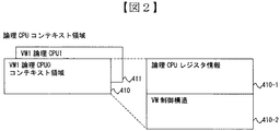
図2に示すように論理CPUのコンテキスト領域には、論理CPUのレジスタ情報410−1や論理CPUのVM制御構造410−2を格納する。 As shown in FIG. 2, the logical CPU register information 410-1 and the logical CPU VM control structure 410-2 are stored in the logical CPU context area.
この論理CPUコンテキスト領域は、物理CPUのコンテキスト610,611,612,613と対応付けられる。
This logical CPU context area is associated with the
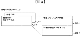
図3に示すように、物理CPUのコンテキストには、レジスタ状態610−1とVM制御構造へのポインタ610−2があり、それぞれが論理CPUのレジスタ情報410−1とVM制御構造410−2と対応する。これらの情報は、プロセス切り替えを契機として、物理CPUとメモリ領域の間でレジスタ情報が退避/回復されたり、VM制御構造のポインタが書き替えられたりする。この処理の詳細は図8で具体例を用いて示す。 As shown in FIG. 3, the physical CPU context includes a register state 610-1 and a pointer 610-2 to the VM control structure, which are logical CPU register information 410-1 and VM control structure 410-2 respectively. Correspond. With regard to these pieces of information, when process switching is performed, register information is saved / recovered between the physical CPU and the memory area, or the pointer of the VM control structure is rewritten. Details of this processing are shown in FIG. 8 using a specific example.
次にVMMデータ部の詳細なデータ構造と、プロセススケジューリングの二つのモードである、CPU占有モードとCPU共有モードについて記す。 Next, a detailed data structure of the VMM data part and two modes of process scheduling, that is, a CPU occupation mode and a CPU sharing mode will be described.
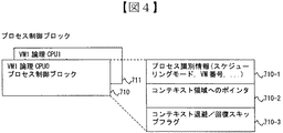
図6および図7は、VMMデータ部の詳細なデータ構造および、CPU占有モード(図6)/共有モード(図7)と呼ぶ二つのスケジューリングモードを表す図である。データ構造、スケジューリングモードの順にその詳細を記す。プロセス制御ブロックは、前述したプログラムを実行する処理単位であるプロセスを、具現化したデータ構造である。プロセスはプログラムの実行に対して、アドレス空間と物理CPUを提供する。プロセスには、仮想計算機のプログラムを実行し、VMの仮想的なCPUを具体化する論理CPUプロセス710,711,720,721,730,731の他に、VMM内部のシステム処理を行うVMM制御用プロセス740,741,742がある。
6 and 7 are diagrams showing a detailed data structure of the VMM data part and two scheduling modes called CPU occupation mode (FIG. 6) / shared mode (FIG. 7). Details are described in the order of data structure and scheduling mode. The process control block is a data structure that embodies a process that is a processing unit for executing the above-described program. A process provides an address space and a physical CPU for program execution. In addition to the logical CPU processes 710, 711, 720, 721, 730, and 731 that execute the virtual machine program and embody the virtual CPU of the VM, the process is for VMM control that performs system processing inside the VMM There are
図4に示すように、各プロセス制御ブロックは、スケジューリングモードやVM番号といったプロセスの識別情報710−1、当該論理CPUのコンテキスト領域へのポインタ710−2、コンテキストの退避/回復スキップを制御するためのフラグ710−3を有する。以降では、単にプロセスといった場合、それを具現化したプロセス制御ブロックのことを指すものとする。 As shown in FIG. 4, each process control block controls process identification information 710-1, such as a scheduling mode and a VM number, a pointer 710-2 to the context area of the logical CPU, and a context save / recovery skip. Flag 710-3. Hereinafter, a simple process means a process control block that embodies it.
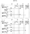
図5のスケジューリング制御テーブル800,801,802,803は、物理CPUごとに設けられ、当該物理CPUにスケジュールされたプロセスに関する情報を有する。図5に示す、当該物理CPUで現在走行しているプロセスの情報800−1、および当該物理CPUで最後に走行した論理CPUプロセスの情報800−2が、これに相当する。 The scheduling control tables 800, 801, 802, and 803 in FIG. 5 are provided for each physical CPU and have information regarding processes scheduled for the physical CPU. The information 800-1 of the process currently running on the physical CPU and the information 800-2 of the logical CPU process last running on the physical CPU shown in FIG. 5 correspond to this.
図6のCPU占有モードでは、論理CPUプロセスが、特定の一つの物理CPU上で占有的にスケジュールされる。 In the CPU occupation mode of FIG. 6, a logical CPU process is scheduled exclusively on a specific physical CPU.
図6では、CPU占有モードのVM1の論理CPUプロセス710,711が、それぞれ物理CPU600,601に占有的にスケジュールされている。ただしCPU占有モードであっても、VMMの内部的な処理を行うための、VMM制御用VMの論理CPUプロセス730,731や、VMMの制御用プロセス740,741,742は、物理CPUの占有状態に関係なく、論理CPUプロセスより優先的に当該物理CPUにスケジュールされる。
In FIG. 6, the
一方、図7のCPU共有モードでは、論理CPUプロセスは、占有モードの論理CPUが排他的に使用する物理CPUを除く任意の物理CPUのうち、いずれか一つにてスケジュールされる。図7では、物理CPU600,601がCPU占有モードとして使用されている。そのため、CPU共有モードのVM2の論理CPUプロセス720,721は、物理CPU602,603に動的にスケジュールされる。CPU占有モードの場合と同じく、VMM制御用VMの論理CPUプロセス730,731や、VMMの制御用プロセス740,741,742は、論理CPUプロセスより優先的に当該物理CPUにスケジュールされる。
On the other hand, in the CPU sharing mode of FIG. 7, the logical CPU process is scheduled by any one of the arbitrary physical CPUs excluding the physical CPU exclusively used by the logical CPU in the exclusive mode. In FIG. 7,
本実施例ではCPU占有モードへの適用を想定して、その実現方式を述べる。 In this embodiment, the implementation method is described assuming application to the CPU occupation mode.
以下、本発明の処理方式について記す。 Hereinafter, the processing method of the present invention will be described.
図8は従来のコンテキストの退避/回復処理の概念図である。図9はこのうちのパターン1についてタイムチャートで示している。 FIG. 8 is a conceptual diagram of a conventional context save / restore process. FIG. 9 is a time chart showing the pattern 1 among them.
今、CPU占有モードの物理CPU600に対し、プロセススケジューリング処理530は、論理CPUプロセス710を占有的にスケジュールしている。論理CPUプロセス710がVM1のプログラムの実行を終えると、プロセススケジューリング処理530は次のプロセスを選択する。例えばここでVMM制御用プロセス740が選択されたとする。論理CPUプロセス710がここで一旦処理を中断するため、プロセススケジューリング処理530は、処理を中断する時点での物理CPUのコンテキストを退避させる。具体的には、対応する論理CPUのコンテキスト領域410に対し、物理CPUのレジスタ状態610−1を論理CPUのレジスタ情報410−1として格納し、VM制御構造へのポインタ610−2によって参照されているVM制御構造410−2へのポインタを解除する。ポインタの解除とは、VM制御構造へのポインタ610−2に書き込まれていたVM1用のアドレスをVMM制御用のアドレスに書き換える(もしくは消す)ことを指す。
Now, for the
VMM制御用プロセス740が処理を終えた後、次に何らかの論理CPUプロセスが選択されるが、CPU占有モードであるため、ここで選択される論理CPUプロセスは、再びVM1の論理CPUプロセスであるか、あるいはVMM制御用VMの論理CPUプロセスのいずれかである。
After the
ここではVM1の論理CPUプロセス710が再び選択されたとする。すると、論理CPUプロセス710がプログラムの実行を始める前に、プロセススケジューリング処理530は対応する領域から先ほど退避したコンテキストを回復させる。具体的には、対応する論理CPUのコンテキスト領域410から、論理CPUのレジスタ情報410−1を再び物理CPUのレジスタに610−1に復元し、VM制御構造410−2を参照できるようにVM制御構造へのポインタ610−2へ登録、つまりアドレスを書き換える(もしくは書き込む)。
Here, it is assumed that the
また、もし、論理CPUプロセス710が処理を終え、次に選択されたプロセスがVMM制御用VMの論理CPUプロセス730であるとすると、論理CPUプロセス710のコンテキストは再び専用の領域へ退避され、VMM制御用VMのコンテキストが回復(復元)される。
Also, if the
これが従来のプロセス切り替えにおける、コンテキスト退避/回復の処理である。この退避/回復は、論理CPUプロセスがスケジュールされるたびに行われる。 This is context saving / recovery processing in the conventional process switching. This save / restore is performed each time a logical CPU process is scheduled.
パターン2はVMM制御用プロセス740の処理の後に、VM1の論理CPUプロセスが連続走行せず、VMM制御用VMの論理CPUプロセスが選択された場合を示している。プロセスの走行順序以外は変わりなく、パターン1と同様に、コンテキストの退避/回復が論理CPUプロセスのスケジュールのたびに行われる。
図10は、本発明の導入により、コンテキストの退避/回復がどのように改善されるかを示した概念図である。図11はこのうちパターン1についてタイムチャートで示している。 FIG. 10 is a conceptual diagram showing how context save / restore is improved by the introduction of the present invention. FIG. 11 shows a time chart for the pattern 1 among them.
図8のパターン1では、VMM制御用プロセス740を介して、連続して同じ論理CPUプロセス710が走行したにも関わらず、プロセス切り替えの度にコンテキストを退避/回復していた。これに対し、本発明(図10)では、プロセス切り替え時にまず、当該プロセスのコンテキストの退避を一旦保留する。具体的には、プロセススケジューリング処理530が、物理CPUのコンテキスト退避、すなわちCPUのレジスタ状態の格納やVM制御構造へのポインタの書き換えを行わずに、プロセス制御ブロックへ退避/回復スキップフラグを立てるように指示をする。これにより、再び連続して同じ論理CPUプロセスが走行した場合は、コンテキスト領域からコンテキストを再度移動する必要がなくなる(回復を行わない)。つまり、同一論理CPUプロセスが連続走行する場合は、一回の退避/回復処理をスキップ(省略)することができ、無駄な処理(オーバーヘッド)を省くことができる。
In the pattern 1 of FIG. 8, the context is saved / recovered every time the process is switched even though the same
パターン2ではVM1の論理CPUプロセス710の間に、VMM制御用VMの論理CPUプロセス730が走行している。パターン1と同じように、VM1の論理CPUプロセスの退避を一旦保留しておくが、間に別の論理CPUプロセスが走行した時点で、保留しておいたVM1の論理CPUプロセスのコンテキストを遅れて退避させる。なお、退避を保留したことや同一のプロセスが走行したことの判定手順については、図12〜図14において詳細を述べる。
In the
コンテキストの退避を保留しても、必要なときには遅れて退避させることで、VMM制御用VMのあとで再びVM1の論理CPUプロセスがスケジュールされた場合も、矛盾なくコンテキストは回復できる。 Even if the context saving is suspended, the context can be recovered without contradiction even if the logical CPU process of the VM1 is scheduled again after the VMM control VM by saving it later when necessary.
図12〜図14はVMMのプロセススケジューリング処理530が、コンテキストの退避/回復をスキップするためのアルゴリズムを表したフローチャートである。処理フローは(1)切り替え元プロセスのコンテキスト退避の要否判定(図12)、(2)切り替え先プロセスのコンテキスト回復の要否判定(図13)、(3)当該物理CPU上で前回走行した論理CPUプロセスの更新(図14)の3つに分けられる。それぞれについて順に記す。
12 to 14 are flowcharts showing an algorithm for the VMM
(1)最初にVMMのプロセススケジューリング処理530は、切り替え元プロセス(現在走行中のプロセス)のコンテキスト退避の要否判定を行う。(図12)
スケジューリング制御テーブルから切り替え元のプロセス情報800−1を取得し、切り替え元プロセスのプロセスの識別情報710−1から、論理CPUプロセスかどうかを判定する。具体的には、プロセス識別情報710−1はそのプロセスの種類を一意に特定できるためのIDを含んでおり、これが論理CPUを示しているかどうか確認する。
(1) First, the VMM
The process information 800-1 of the switching source is acquired from the scheduling control table, and it is determined from the process identification information 710-1 of the switching source process whether it is a logical CPU process. Specifically, the process identification information 710-1 includes an ID for uniquely identifying the type of the process, and checks whether this indicates a logical CPU.
切り替え元プロセスが論理CPUプロセスでない場合は、コンテキストの退避は必要ないので、(2)の処理に移行する。 If the switching source process is not a logical CPU process, it is not necessary to save the context, and the process proceeds to (2).
切り替え元プロセスが論理CPUプロセスである場合、次にプロセスの識別情報710−1から、切り替え元プロセスのVMが「CPU占有モードであり、かつ、(VMM制御用VMでない)ユーザ定義VM」かどうかを判定する。 If the switching source process is a logical CPU process, whether or not the VM of the switching source process is “CPU-occupied mode and is not a VMM control VM” is determined from the process identification information 710-1. Determine.
切り替え元プロセスのVMが、CPU共有モードであったか、またはVMM制御用のVMであった場合はスキップできないと判定し、コンテキストを退避する。すなわち、図15に示すように、コンテキスト領域へのポインタ710−2から対応するコンテキスト領域410を取得して、物理CPUのレジスタ状態610−1を論理CPUのレジスタ情報410−1として格納し、VM制御構造へのポインタ610−2によって参照されているVM制御構造410−2へのポインタを解除する。このとき、レジスタ情報に関しては、コンテキストを退避する論理CPUプロセスがVMM制御用VMのものであった場合は、例えばCPU固有情報が格納されたレジスタなどを除き、VMの走行に影響するものだけを退避する。
If the VM of the switching source process is in the CPU sharing mode or the VM for VMM control, it is determined that it cannot be skipped, and the context is saved. That is, as shown in FIG. 15, the corresponding
切り替え元プロセスのVMが、CPU占有モードであり、かつVM1やVM2などのユーザが定義したVMであった場合は、退避/回復をスキップできる可能性がある。プロセススケジューリング処理530は、物理CPUコンテキスト610をそのまま保持し、コンテキスト退避/回復スキップフラグ710−3をオンにして退避を保留する。
If the VM of the switching source process is in the CPU occupation mode and is a VM defined by the user such as VM1 or VM2, there is a possibility that the saving / recovery can be skipped. The
(2)次にVMMのプロセススケジューリング処理530は、切り替え先プロセスのコンテキスト回復の要否判定を行う。(図13)
まず、切り替え先プロセスのプロセスの識別情報710−1から、論理CPUプロセスかどうかを判定する。(1)の最初の動作と同じである。
(2) Next, the VMM
First, it is determined from the process identification information 710-1 of the switching destination process whether or not it is a logical CPU process. This is the same as the first operation of (1).
切り替え先プロセスが論理CPUプロセスではない場合は、コンテキストの回復は必要ないので、(3)の処理に移行する。 If the switching destination process is not a logical CPU process, it is not necessary to recover the context, and the process proceeds to (3).
切り替え先プロセスが論理CPUプロセスである場合は、スケジューリング制御テーブルから前回論理CPUプロセス情報800−2を取得し、切り替え先プロセスが前回論理CPUプロセス(当該物理CPUで最後に走行した論理CPUプロセス)と等しいかどうかの判定を行う。条件が成立しない場合とする場合の処理について、それぞれ(2.1)、(2.2)に記す。
If the switching destination process is a logical CPU process, the previous logical CPU process information 800-2 is acquired from the scheduling control table, and the switching destination process is the previous logical CPU process (the logical CPU process that last ran on the physical CPU). Determine if they are equal. The processing when the condition is not satisfied is described in (2.1) and (2.2), respectively.
(2.1)切り替え先プロセスと前回論理CPUプロセスが等しくない場合は、回復をスキップできない。このとき、前回論理CPUプロセスの退避/回復スキップフラグのオン/オフにより動作が異なる。 (2.1) If the switching destination process and the previous logical CPU process are not equal, recovery cannot be skipped. At this time, the operation differs depending on ON / OFF of the save / recovery skip flag of the previous logical CPU process.
前回論理CPUプロセスの退避/回復スキップフラグがオンである場合は、(1)で退避を保留しておいたが、同じ論理CPUプロセスが連続で走行しなかったケースである。このため、退避を保留した前回論理CPUプロセスのコンテキストをこの時点で退避して、退避/回復スキップフラグをオフにする。 When the previous logical CPU process save / recovery skip flag is on, the save was suspended in (1), but the same logical CPU process did not run continuously. For this reason, the context of the previous logical CPU process for which saving has been suspended is saved at this time, and the save / recovery skip flag is turned off.
退避/回復スキップフラグがオフである場合は、前回論理CPUプロセスのコンテキストは退避してある状態なので、何もしない。 If the save / recovery skip flag is off, the previous logical CPU process context has been saved, so nothing is done.
どちらにしても、最後に切り替え先のコンテキストを回復する。図16に示すように、コンテキスト領域へのポインタ710−2から対応するコンテキスト領域410を取得して、論理CPUのレジスタ情報410−1を物理CPUのレジスタに610−1に復元し、VM制御構造410−2を参照できるようにVM制御構造へのポインタ610−2へ登録しする。このとき、レジスタ情報は、コンテキストを退避する論理CPUプロセスがVMM制御用VMのものであった場合は、前述通り必要なものに限定して退避させたものを回復する。切り替え先のコンテキスト回復処理を終えると、(3)の処理に移行する。
In any case, the context of the switching destination is finally recovered. As shown in FIG. 16, the corresponding
(2.2)切り替え先プロセスと前回論理CPUプロセスが等しい場合は、回復をスキップできる可能性がある。 (2.2) If the switching destination process and the previous logical CPU process are equal, there is a possibility that recovery can be skipped.
しかし、前回論理CPUプロセスの退避/回復スキップフラグがオフである場合は、CPU共有モードなどで退避を保留しなかった場合なのでスキップできない。この場合は、切り替え先のコンテキストを回復し、(3)の処理に移行する。 However, if the previous logical CPU process save / recovery skip flag is OFF, the save cannot be skipped because the save is not suspended in the CPU sharing mode or the like. In this case, the context of the switching destination is recovered, and the process proceeds to (3).
前回論理CPUプロセスのスキップフラグがオンである場合が、回復をスキップできるケースである。これは、(1)で退避を保留しておき、再び同じ論理CPUプロセスが走行する場合なので、退避/回復スキップフラグをオフにし、前回論理CPUプロセスのコンテキスト退避処理や切り替え先プロセスのコンテキスト回復処理は行わず、退避/回復をスキップする。 The case where the skip flag of the previous logical CPU process is on is a case where recovery can be skipped. This is because the saving is suspended in (1) and the same logical CPU process runs again, so the saving / recovery skip flag is turned off, and the previous logical CPU process context saving process or the switching destination process context recovery process No evacuation / recovery is skipped.
(3)最後にVMMのプロセススケジューリング処理530は、前回論理CPUプロセスの更新処理を行う。(図14)
切り替え先のプロセスが論理CPUプロセスである場合、当該物理CPUのスケジューリング制御テーブル800の前回論理CPUプロセス情報800−2を、切り替え先プロセスに更新する。
(3) Finally, the VMM
When the switching destination process is a logical CPU process, the previous logical CPU process information 800-2 in the scheduling control table 800 of the physical CPU is updated to the switching destination process.
これら図12〜図14の処理は全てプロセススケジューリング処理530が行う。
All of the processes of FIGS. 12 to 14 are performed by a
以上のように、CPU占有モードにおいては、コンテキストの退避/回復のスキップによって、オーバーヘッドの削減に貢献できる。 As described above, in the CPU occupation mode, it is possible to contribute to the reduction of overhead by skipping context save / restore.
この方式はCPU共有モードにも適用が可能である。しかしながら、CPU共有モードは上に述べたように、任意の物理CPUのうち、いずれか一つにスケジュールするため、同一の論理CPUプロセスが連続走行する可能性は少なく、多くの場合でコンテキストを退避/回復させなくてはならない。よって共有モードに退避をスキップする機能を持たせる意味は少ないが、処理のタイミングによっては、退避/回復をスキップすることも有効である。 This method can also be applied to the CPU sharing mode. However, since the CPU sharing mode is scheduled to any one of the arbitrary physical CPUs as described above, there is little possibility that the same logical CPU process runs continuously, and in many cases the context is saved. / It must be recovered. Therefore, it is not meaningful to have a function to skip saving in the shared mode, but it is also effective to skip saving / restoring depending on the processing timing.
VMMのコンテキスト切り替えによるオーバーヘッドを削減することができる。これによって、CPUリソースの効率的な運用が可能となり、汎用的な処理性能の向上が見込める。特にデータベースシステムなど、I/O割り込みによるプロセス切り替えが頻発に起こるシステムにおいて、性能の向上が期待でき、仮想計算機システムの適応範囲の拡大が可能となる。 Overhead due to VMM context switching can be reduced. As a result, efficient operation of CPU resources becomes possible, and general-purpose processing performance can be improved. In particular, in a system such as a database system where process switching due to I / O interruptions occurs frequently, an improvement in performance can be expected, and the adaptive range of the virtual machine system can be expanded.
100,200,300 仮想計算機(VM)
110,210,310 ゲストオペレーティングシステム(OS)
120,121,220,221,320,321 論理CPU
130,230,330 VM用メモリ
400 VMM制御用のメモリ領域
410,411,420,421,430,431 論理CPUコンテキスト格納用領域
410−1 論理CPUのレジスタ情報
410−2 論理CPUのVM制御構造
500 仮想マシンモニタ(VMM)
510 プロセス制御ブロック
520 スケジューリング制御テーブル
530 プロセススケジューリング処理
600,601,602,603 物理CPU
610,611,612,613 物理CPUコンテキスト
610−1 物理CPUレジスタ状態
610−2 VM制御構造へのポインタ
620,621,622 物理CPU内部メモリ
710,711,720,721,730,731,740,741,742 各プロセス制御ブロック
710−1 プロセス識別情報
710−2 コンテキスト格納領域へのポインタ
710−3 コンテキスト退避/回復スキップフラグ
800,801,802,803 各スケジューリング制御テーブル
810−1 当該物理CPUで現在走行中のプロセス
810−2 当該物理CPUで最後に走行した論理CPUプロセス
100, 200, 300 Virtual machines (VM)
110, 210, 310 Guest operating system (OS)
120, 121, 220, 221, 320, 321 Logical CPU
130, 230, 330 Memory for
510
610, 611, 612, 613 Physical CPU context 610-1 Physical CPU register state 610-2 Pointer to
Claims (5)
前記仮想計算機は、前記複数の仮想計算機が前記物理CPUを共有するCPU共有モードと、前記複数の仮想計算機のうちの特定の仮想計算機が前記物理CPUを占有するCPU占有モードとを有し、
前記物理CPUは、動作中のプロセスに対応づけられた物理コンテキストを格納する内部メモリを有し、
前記仮想計算機制御メモリは、前記物理コンテキストと対応づけられた論理コンテキスト領域を有し、
前記プロセスは、前記仮想計算機の論理CPUのプロセスである第1の論理CPUプロセス、前記仮想計算機制御部用の仮想計算機の論理CPUのプロセスである第2の論理CPUプロセス、及び前記仮想計算機制御部の制御プロセスのうち何れか1つであり、
前記仮想計算機制御部は、前記仮想計算機のプロセス切り替え時における前記論理コンテキスト領域への前記物理コンテキストの退避動作を管理するプロセス制御ブロックを有し、
前記仮想計算機制御部が、次のプロセスとして前記制御プロセスを選択すると、
前記物理CPUで動作中のプロセスが前記第1の論理CPUプロセス及び前記第2の論理CPUプロセスのいずれであるかを判定し、
前記判定により、前記動作中のプロセスが前記CPU占有モードの第1の論理CPUプロセスである場合、前記仮想計算機制御部が、動作中のプロセスに対応づけられた物理コンテキストの退避を保留する前記プロセス制御ブロックの保留フラグをオンにし、
前記判定により、前記動作中のプロセスが前記CPU共有モードの第1の論理CPUプロセスである場合、前記仮想計算機制御部が、前記動作中のプロセスに対応づけられた物理コンテキストの退避を保留する前記プロセス制御ブロックの保留フラグをオフにし、
前記CPU共有モードの第1の論理CPUプロセスに対応づけられた物理コンテキストを、対応する前記論理コンテキスト領域に退避させ、
前記判定により、前記動作中のプロセスが前記第2の論理CPUプロセスである場合、前記仮想計算機制御部が、前記動作中のプロセスに対応づけられた物理コンテキストの退避を保留する前記プロセス制御ブロックの保留フラグをオフにし、
前記第2の論理CPUプロセスに対応づけられた物理コンテキストを、対応する前記論理コンテキスト領域に退避させ、
前記仮想計算機制御部が、前記制御プロセスの次のプロセスとして前記第1の論理CPUプロセスを選択すると、前記仮想計算機制御部は、前記制御プロセスの前に動作した論理CPUプロセスにおける前記保留フラグを参照し、
前記参照した保留フラグがオンである場合、前記物理CPUは、退避を保留した前記内部メモリの前記物理コンテキストを参照して、前記CPU占有モードの第1の論理CPUプロセスを実行し、前記仮想計算機制御部が前記参照した保留フラグをオフにし、
前記参照した保留フラグがオフである場合、前記仮想計算機制御部は、前記論理コンテキスト領域から前記CPU共有モードの第1の論理CPUプロセスに対応する物理コンテキストを前記内部メモリに復元し、
前記物理CPUは、前記復元した前記CPU共有モードの第1の論理CPUプロセスに対応する物理コンテキストを参照して、前記CPU共有モードの第1の論理CPUプロセスを実行し、
前記仮想計算機制御部が、前記制御プロセスの次のプロセスとして前記第2の論理CPUプロセスを選択すると、前記仮想計算機制御部は、前記制御プロセスの前に動作した論理CPUプロセスにおける前記保留フラグを参照し、
前記参照した保留フラグがオンである場合、退避を保留した前記内部メモリの前記物理コンテキストを、対応する前記論理コンテキスト領域に退避し、前記参照した保留フラグをオフにし、
前記仮想計算機制御部は、前記論理コンテキスト領域から前記第2の論理CPUプロセスに対応する物理コンテキストを前記内部メモリに復元し、
前記物理CPUは、前記復元した第2の論理CPUプロセスに対応する物理コンテキストを参照して、前記第2の論理CPUプロセスを実行し、
前記参照した保留フラグがオフである場合、
前記仮想計算機制御部は、前記論理コンテキスト領域から前記第2の論理CPUプロセスに対応する物理コンテキストを前記内部メモリに復元し、
前記物理CPUは、前記復元した第2の論理CPUプロセスに対応する物理コンテキストを参照して、前記第2の論理CPUプロセスを実行する
ことを特徴とする仮想計算機システム。 A virtual machine system comprising: a physical CPU; a virtual machine controller that logically divides the physical CPU into a plurality of virtual machines; and a virtual machine control memory that the virtual machine controller uses to control the virtual machine In
The virtual machine has a CPU sharing mode in which the plurality of virtual machines share the physical CPU, and a CPU occupation mode in which a specific virtual machine of the plurality of virtual machines occupies the physical CPU,
The physical CPU has an internal memory for storing a physical context associated with a running process;
The virtual machine control memory has a logical context area associated with the physical context,
The process includes a first logical CPU process that is a logical CPU process of the virtual machine, a second logical CPU process that is a logical CPU process of the virtual machine controller for the virtual machine control unit, and the virtual machine control unit. One of the control processes of
The virtual machine control unit has a process control block that manages a save operation of the physical context to the logical context area at the time of process switching of the virtual machine,
When the virtual machine control unit selects the control process as the next process,
Determining whether the process running on the physical CPU is the first logical CPU process or the second logical CPU process;
If it is determined that the operating process is the first logical CPU process in the CPU occupation mode, the virtual machine controller holds the saving of the physical context associated with the operating process. Turn on the hold flag in the control block,
As a result of the determination, when the operating process is the first logical CPU process in the CPU sharing mode, the virtual machine control unit suspends saving of the physical context associated with the operating process. Turn off the pending flag in the process control block,
Saving the physical context associated with the first logical CPU process in the CPU sharing mode to the corresponding logical context area;
As a result of the determination, when the operating process is the second logical CPU process, the virtual machine control unit holds the save of the physical context associated with the operating process. Turn off the hold flag,
Saving the physical context associated with the second logical CPU process in the corresponding logical context area;
When the virtual machine control unit selects the first logical CPU process as the next process of the control process, the virtual machine control unit refers to the hold flag in the logical CPU process operating before the control process. And
If the referenced hold flag is on, the physical CPU executes the first logical CPU process in the CPU occupation mode with reference to the physical context of the internal memory that has held the save, and the virtual machine The control unit turns off the pending flag referred to above,
When the referenced pending flag is off, the virtual machine controller restores the physical context corresponding to the first logical CPU process in the CPU sharing mode from the logical context area to the internal memory,
The physical CPU refers to the physical context corresponding to the first logical CPU process of the CPU sharing mode that the recovered, performing a first logical CPU process of the CPU sharing mode,
When the virtual machine control unit selects the second logical CPU process as the next process of the control process, the virtual machine control unit refers to the hold flag in the logical CPU process operating before the control process. And
If the referenced hold flag is on, the physical context of the internal memory that has been saved is saved in the corresponding logical context area, the referenced hold flag is turned off,
The virtual machine control unit restores a physical context corresponding to the second logical CPU process from the logical context area to the internal memory,
The physical CPU refers to a physical context corresponding to the restored second logical CPU process, and executes the second logical CPU process;
If the referenced hold flag is off,
The virtual machine control unit restores a physical context corresponding to the second logical CPU process from the logical context area to the internal memory,
The virtual machine system, wherein the physical CPU executes the second logical CPU process with reference to a physical context corresponding to the restored second logical CPU process.
前記仮想計算機制御部は、前記論理コンテキスト領域に退避した前記物理コンテキストを、前記内部メモリに復元し、
前記物理CPUは、復元された前記内部メモリの前記物理コンテキストを参照して、前記第1の論理CPUプロセスを実行すること
を特徴とする請求項1記載の仮想計算機システム。 When the virtual machine control unit selects the first logical CPU process as a process next to the second logical CPU process,
The virtual machine control unit restores the physical context saved in the logical context area to the internal memory,
The virtual machine system according to claim 1, wherein the physical CPU executes the first logical CPU process with reference to the physical context of the restored internal memory.
前記論理コンテキスト領域は、前記物理CPUレジスタ状態情報に対応する論理CPUレジスタ情報と、前記仮想計算機制御構造へのポインタ情報に対応する仮想計算機制御構造情報とを有することを特徴とする請求項1記載の仮想計算機システム。 The physical context has physical CPU register status information and pointer information to the virtual machine control structure,
2. The logical context area includes logical CPU register information corresponding to the physical CPU register state information and virtual machine control structure information corresponding to pointer information to the virtual machine control structure. Virtual computer system.
前記仮想計算機は、前記複数の仮想計算機が前記物理CPUを共有するCPU共有モードと、前記複数の仮想計算機のうちの特定の仮想計算機が前記物理CPUを占有するCPU占有モードとを有し、
前記物理CPUは、動作中のプロセスに対応づけられた物理コンテキストを格納する内部メモリを有し、
前記仮想計算機制御メモリは、前記物理コンテキストと対応づけられた論理コンテキスト領域を有し、
前記プロセスは、前記仮想計算機の論理CPUのプロセスである第1の論理CPUプロセス、前記仮想計算機制御部用の仮想計算機の論理CPUのプロセスである第2の論理CPUプロセス、及び前記仮想計算機制御部の制御プロセスのうち何れか1つであり、
前記仮想計算機制御部は、
前記仮想計算機のプロセス切り替え時における前記論理コンテキスト領域への前記物理コンテキストの退避動作を管理するプロセス制御ブロックを有し、
次のプロセスとして前記制御プロセスを選択すると、
前記物理CPUで動作中のプロセスが前記第1の論理CPUプロセス及び前記第2の論理CPUプロセスのいずれであるかを判定し、
前記判定により、前記動作中のプロセスが前記CPU占有モードの第1の論理CPUプロセスである場合、前記仮想計算機制御部が、動作中のプロセスに対応づけられた物理コンテキストの退避を保留する前記プロセス制御ブロックの保留フラグをオンにし、
前記判定により、前記動作中のプロセスが前記CPU共有モードの第1の論理CPUプロセスである場合、前記仮想計算機制御部が、前記動作中のプロセスに対応づけられた物理コンテキストの退避を保留する前記プロセス制御ブロックの保留フラグをオフにし、
前記CPU共有モードの第1の論理CPUプロセスに対応づけられた物理コンテキストを、対応する前記論理コンテキスト領域に退避させ、
前記判定により、前記動作中のプロセスが前記第2の論理CPUプロセスである場合、前記仮想計算機制御部が、前記動作中のプロセスに対応づけられた物理コンテキストの退避を保留する前記プロセス制御ブロックの保留フラグをオフにし、
前記第2の論理CPUプロセスに対応づけられた物理コンテキストを、対応する前記論理コンテキスト領域に退避させ、
前記仮想計算機制御部は、
前記制御プロセスの次のプロセスとして前記第1の論理CPUプロセスを選択すると、前記制御プロセスの前に動作した論理CPUプロセスにおける前記保留フラグを参照し、
前記参照した保留フラグがオンである場合、前記物理CPUにより、退避を保留した前記内部メモリの前記物理コンテキストを参照して、前記CPU占有モードの第1の論理CPUプロセスが実行され、前記仮想計算機制御部が前記参照した保留フラグをオフにし、
前記参照した保留フラグがオフである場合、前記論理コンテキスト領域から前記CPU共有モードの第1の論理CPUプロセスに対応する物理コンテキストを前記内部メモリに復元し、
前記物理CPUにより、前記復元した前記CPU共有モードの第1の論理CPUプロセスに対応する物理コンテキストを参照して、前記CPU共有モードの第1の論理CPUプロセスが実行され、
前記制御プロセスの次のプロセスとして前記第2の論理CPUプロセスを選択すると、前記制御プロセスの前に動作した論理CPUプロセスにおける前記保留フラグを参照し、
前記参照した保留フラグがオンである場合、退避を保留した前記内部メモリの前記物理コンテキストを、対応する前記論理コンテキスト領域に退避し、前記参照した保留フラグをオフにし、
前記論理コンテキスト領域から前記第2の論理CPUプロセスに対応する物理コンテキストを前記内部メモリに復元し、
前記物理CPUにより、前記復元した第2の論理CPUプロセスに対応する物理コンテキストを参照して、前記第2の論理CPUプロセスが実行され、
前記参照した保留フラグがオフである場合、
前記論理コンテキスト領域から前記第2の論理CPUプロセスに対応する物理コンテキストを前記内部メモリに復元し、
前記物理CPUにより、前記復元した第2の論理CPUプロセスに対応する物理コンテキストを参照して、前記第2の論理CPUプロセスが実行される
ことを特徴とする仮想計算機制御部。 A virtual machine system comprising: a physical CPU; a virtual machine controller that logically divides the physical CPU into a plurality of virtual machines; and a virtual machine control memory that the virtual machine controller uses to control the virtual machine A virtual machine control unit in
The virtual machine has a CPU sharing mode in which the plurality of virtual machines share the physical CPU, and a CPU occupation mode in which a specific virtual machine of the plurality of virtual machines occupies the physical CPU,
The physical CPU has an internal memory for storing a physical context associated with a running process;
The virtual machine control memory has a logical context area associated with the physical context,
The process includes a first logical CPU process that is a logical CPU process of the virtual machine, a second logical CPU process that is a logical CPU process of the virtual machine controller for the virtual machine control unit, and the virtual machine control unit. One of the control processes of
The virtual machine controller is
A process control block for managing a save operation of the physical context in the logical context area at the time of process switching of the virtual machine;
When the control process is selected as the next process,
Determining whether the process running on the physical CPU is the first logical CPU process or the second logical CPU process;
If it is determined that the operating process is the first logical CPU process in the CPU occupation mode, the virtual machine controller holds the saving of the physical context associated with the operating process. Turn on the hold flag in the control block,
As a result of the determination, when the operating process is the first logical CPU process in the CPU sharing mode, the virtual machine control unit suspends saving of the physical context associated with the operating process. Turn off the pending flag in the process control block,
Saving the physical context associated with the first logical CPU process in the CPU sharing mode to the corresponding logical context area;
As a result of the determination, when the operating process is the second logical CPU process, the virtual machine control unit holds the save of the physical context associated with the operating process. Turn off the hold flag,
Saving the physical context associated with the second logical CPU process in the corresponding logical context area;
The virtual machine controller is
When the first logical CPU process is selected as the next process of the control process, the pending flag in the logical CPU process that operates before the control process is referred to.
When the referred hold flag is ON, the physical CPU executes the first logical CPU process in the CPU occupation mode with reference to the physical context of the internal memory where the save is held, and the virtual machine The control unit turns off the pending flag referred to above,
If the referenced pending flag is off, the physical context corresponding to the first logical CPU process in the CPU sharing mode is restored from the logical context area to the internal memory;
Wherein the physical CPU, with reference to the physical context corresponding to the first logical CPU process of the CPU shared mode with the restoration, the first logical CPU process of the CPU sharing mode is executed,
When the second logical CPU process is selected as the next process of the control process, the pending flag in the logical CPU process that operates before the control process is referred to.
If the referenced hold flag is on, the physical context of the internal memory that has been saved is saved in the corresponding logical context area, the referenced hold flag is turned off,
Restoring a physical context corresponding to the second logical CPU process from the logical context area to the internal memory;
The second logical CPU process is executed by the physical CPU with reference to a physical context corresponding to the restored second logical CPU process,
If the referenced hold flag is off,
Restoring a physical context corresponding to the second logical CPU process from the logical context area to the internal memory;
The virtual machine control unit, wherein the physical CPU executes the second logical CPU process with reference to a physical context corresponding to the restored second logical CPU process.
前記仮想計算機は、前記複数の仮想計算機が前記物理CPUを共有するCPU共有モードと、前記複数の仮想計算機のうちの特定の仮想計算機が前記物理CPUを占有するCPU占有モードとを有し、
前記物理CPUは、動作中のプロセスに対応づけられた物理コンテキストを格納する内部メモリを有し、
前記仮想計算機制御メモリは、前記物理コンテキストと対応づけられた論理コンテキスト領域を有し、
前記プロセスは、前記仮想計算機の論理CPUのプロセスである第1の論理CPUプロセス、前記仮想計算機制御部用の仮想計算機の論理CPUのプロセスである第2の論理CPUプロセス、及び前記仮想計算機制御部の制御プロセスのうち何れか1つであり、
前記仮想計算機制御部は、前記仮想計算機のプロセス切り替え時における前記論理コンテキスト領域への前記物理コンテキストの退避動作を管理するプロセス制御ブロックを有し、
前記仮想計算機制御部が、次のプロセスとして前記制御プロセスを選択すると、
前記物理CPUで動作中のプロセスが前記第1の論理CPUプロセス及び前記第2の論理CPUプロセスのいずれであるかを判定し、
前記判定により、前記動作中のプロセスが前記CPU占有モードの第1の論理CPUプロセスである場合、前記仮想計算機制御部が、動作中のプロセスに対応づけられた物理コンテキストの退避を保留する前記プロセス制御ブロックの保留フラグをオンにし、
前記判定により、前記動作中のプロセスが前記CPU共有モードの第1の論理CPUプロセスである場合、前記仮想計算機制御部が、前記動作中のプロセスに対応づけられた物理コンテキストの退避を保留する前記プロセス制御ブロックの保留フラグをオフにし、
前記CPU共有モードの第1の論理CPUプロセスに対応づけられた物理コンテキストを、対応する前記論理コンテキスト領域に退避させ、
前記判定により、前記動作中のプロセスが前記第2の論理CPUプロセスである場合、前記仮想計算機制御部が、前記動作中のプロセスに対応づけられた物理コンテキストの退避を保留する前記プロセス制御ブロックの保留フラグをオフにし、
前記第2の論理CPUプロセスに対応づけられた物理コンテキストを、対応する前記論理コンテキスト領域に退避させ、
前記仮想計算機制御部が、前記制御プロセスの次のプロセスとして前記第1の論理CPUプロセスを選択すると、前記仮想計算機制御部は、前記制御プロセスの前に動作した論理CPUプロセスにおける前記保留フラグを参照し、
前記参照した保留フラグがオンである場合、前記物理CPUは、退避を保留した前記内部メモリの前記物理コンテキストを参照して、前記CPU占有モードの第1の論理CPUプロセスを実行し、前記仮想計算機制御部が前記参照した保留フラグをオフにし、
前記参照した保留フラグがオフである場合、前記仮想計算機制御部は、前記論理コンテキスト領域から前記CPU共有モードの第1の論理CPUプロセスに対応する物理コンテキストを前記内部メモリに復元し、
前記物理CPUは、前記復元した前記CPU共有モードの第1の論理CPUプロセスに対応する物理コンテキストを参照して、前記CPU共有モードの第1の論理CPUプロセスを実行し、
前記仮想計算機制御部が、前記制御プロセスの次のプロセスとして前記第2の論理CPUプロセスを選択すると、前記仮想計算機制御部は、前記制御プロセスの前に動作した論理CPUプロセスにおける前記保留フラグを参照し、
前記参照した保留フラグがオンである場合、退避を保留した前記内部メモリの前記物理コンテキストを、対応する前記論理コンテキスト領域に退避し、前記参照した保留フラグをオフにし、
前記仮想計算機制御部は、前記論理コンテキスト領域から前記第2の論理CPUプロセスに対応する物理コンテキストを前記内部メモリに復元し、
前記物理CPUは、前記復元した第2の論理CPUプロセスに対応する物理コンテキストを参照して、前記第2の論理CPUプロセスを実行し、
前記参照した保留フラグがオフである場合、
前記仮想計算機制御部は、前記論理コンテキスト領域から前記第2の論理CPUプロセスに対応する物理コンテキストを前記内部メモリに復元し、
前記物理CPUは、前記復元した第2の論理CPUプロセスに対応する物理コンテキストを参照して、前記第2の論理CPUプロセスを実行する
ことを特徴とするスケジューリング方法。 A virtual machine system comprising: a physical CPU; a virtual machine controller that logically divides the physical CPU into a plurality of virtual machines; and a virtual machine control memory that the virtual machine controller uses to control the virtual machine Scheduling method in which
The virtual machine has a CPU sharing mode in which the plurality of virtual machines share the physical CPU, and a CPU occupation mode in which a specific virtual machine of the plurality of virtual machines occupies the physical CPU,
The physical CPU has an internal memory for storing a physical context associated with a running process;
The virtual machine control memory has a logical context area associated with the physical context,
The process includes a first logical CPU process that is a logical CPU process of the virtual machine, a second logical CPU process that is a logical CPU process of the virtual machine controller for the virtual machine control unit, and the virtual machine control unit. One of the control processes of
The virtual machine control unit has a process control block that manages a save operation of the physical context to the logical context area at the time of process switching of the virtual machine,
When the virtual machine control unit selects the control process as the next process,
Determining whether the process running on the physical CPU is the first logical CPU process or the second logical CPU process;
If it is determined that the operating process is the first logical CPU process in the CPU occupation mode, the virtual machine controller holds the saving of the physical context associated with the operating process. Turn on the hold flag in the control block,
As a result of the determination, when the operating process is the first logical CPU process in the CPU sharing mode, the virtual machine control unit suspends saving of the physical context associated with the operating process. Turn off the pending flag in the process control block,
Saving the physical context associated with the first logical CPU process in the CPU sharing mode to the corresponding logical context area;
As a result of the determination, when the operating process is the second logical CPU process, the virtual machine control unit holds the save of the physical context associated with the operating process. Turn off the hold flag,
Saving the physical context associated with the second logical CPU process in the corresponding logical context area;
When the virtual machine control unit selects the first logical CPU process as the next process of the control process, the virtual machine control unit refers to the hold flag in the logical CPU process operating before the control process. And
If the referenced hold flag is on, the physical CPU executes the first logical CPU process in the CPU occupation mode with reference to the physical context of the internal memory that has held the save, and the virtual machine The control unit turns off the pending flag referred to above,
When the referenced pending flag is off, the virtual machine controller restores the physical context corresponding to the first logical CPU process in the CPU sharing mode from the logical context area to the internal memory,
The physical CPU refers to the physical context corresponding to the first logical CPU process of the CPU sharing mode that the recovered, performing a first logical CPU process of the CPU sharing mode,
When the virtual machine control unit selects the second logical CPU process as the next process of the control process, the virtual machine control unit refers to the hold flag in the logical CPU process operating before the control process. And
If the referenced hold flag is on, the physical context of the internal memory that has been saved is saved in the corresponding logical context area, the referenced hold flag is turned off,
The virtual machine control unit restores a physical context corresponding to the second logical CPU process from the logical context area to the internal memory,
The physical CPU refers to a physical context corresponding to the restored second logical CPU process, and executes the second logical CPU process;
If the referenced hold flag is off,
The virtual machine control unit restores a physical context corresponding to the second logical CPU process from the logical context area to the internal memory,
The physical CPU executes the second logical CPU process with reference to a physical context corresponding to the restored second logical CPU process.
Priority Applications (2)
| Application Number | Priority Date | Filing Date | Title |
|---|---|---|---|
| JP2008306964A JP4871948B2 (en) | 2008-12-02 | 2008-12-02 | Virtual computer system, hypervisor in virtual computer system, and scheduling method in virtual computer system |
| US12/628,342 US8266629B2 (en) | 2008-12-02 | 2009-12-01 | Virtual machine system, hypervisor in virtual machine system, and scheduling method in virtual machine system |
Applications Claiming Priority (1)
| Application Number | Priority Date | Filing Date | Title |
|---|---|---|---|
| JP2008306964A JP4871948B2 (en) | 2008-12-02 | 2008-12-02 | Virtual computer system, hypervisor in virtual computer system, and scheduling method in virtual computer system |
Publications (3)
| Publication Number | Publication Date |
|---|---|
| JP2010134496A JP2010134496A (en) | 2010-06-17 |
| JP2010134496A5 JP2010134496A5 (en) | 2010-12-09 |
| JP4871948B2 true JP4871948B2 (en) | 2012-02-08 |
Family
ID=42223944
Family Applications (1)
| Application Number | Title | Priority Date | Filing Date |
|---|---|---|---|
| JP2008306964A Expired - Fee Related JP4871948B2 (en) | 2008-12-02 | 2008-12-02 | Virtual computer system, hypervisor in virtual computer system, and scheduling method in virtual computer system |
Country Status (2)
| Country | Link |
|---|---|
| US (1) | US8266629B2 (en) |
| JP (1) | JP4871948B2 (en) |
Families Citing this family (22)
| Publication number | Priority date | Publication date | Assignee | Title |
|---|---|---|---|---|
| WO2011142733A1 (en) * | 2010-05-11 | 2011-11-17 | Thomson Licensing | A configurable computing architecture |
| US8812400B2 (en) * | 2010-07-09 | 2014-08-19 | Hewlett-Packard Development Company, L.P. | Managing a memory segment using a memory virtual appliance |
| WO2012086106A1 (en) * | 2010-12-21 | 2012-06-28 | パナソニック株式会社 | Virtual computer system and virtual computer system control method |
| KR101773166B1 (en) | 2011-02-21 | 2017-08-30 | 삼성전자주식회사 | Apparatus and method for control of virtual machine schedule time |
| US8555279B2 (en) * | 2011-04-25 | 2013-10-08 | Hitachi, Ltd. | Resource allocation for controller boards management functionalities in a storage management system with a plurality of controller boards, each controller board includes plurality of virtual machines with fixed local shared memory, fixed remote shared memory, and dynamic memory regions |
| US8793535B2 (en) | 2011-07-21 | 2014-07-29 | Microsoft Corporation | Optimizing system usage when running quality tests in a virtual machine environment |
| US9459898B2 (en) * | 2011-10-06 | 2016-10-04 | Hitachi, Ltd. | Virtual server processing control method, system, and virtual server processing control management server |
| JP5936041B2 (en) * | 2012-03-07 | 2016-06-15 | 日本電気株式会社 | Multiprocessor device, scheduling method, and scheduling program |
| CN102750178B (en) | 2012-06-08 | 2015-04-29 | 华为技术有限公司 | Virtualization management method of communication equipment hardware resources, and device related to method |
| US9569223B2 (en) * | 2013-02-13 | 2017-02-14 | Red Hat Israel, Ltd. | Mixed shared/non-shared memory transport for virtual machines |
| US9262198B2 (en) * | 2013-08-26 | 2016-02-16 | Vmware, Inc. | CPU scheduler configured to support latency sensitive virtual machines |
| CN103699433B (en) * | 2013-12-18 | 2017-07-14 | 中国科学院计算技术研究所 | One kind dynamically adjusts number of tasks purpose method and system in Hadoop platform |
| CN103729252B (en) * | 2013-12-20 | 2017-09-05 | 杭州华为数字技术有限公司 | The method and dispatching and monitoring device of a kind of scheduling virtual machine |
| US9772867B2 (en) * | 2014-03-27 | 2017-09-26 | International Business Machines Corporation | Control area for managing multiple threads in a computer |
| JP6158751B2 (en) * | 2014-05-30 | 2017-07-05 | 日本電信電話株式会社 | Computer resource allocation apparatus and computer resource allocation program |
| CN104035811B (en) * | 2014-07-01 | 2017-07-28 | 龙芯中科技术有限公司 | The treating method and apparatus of virtual machine field data |
| US10127068B2 (en) * | 2016-06-30 | 2018-11-13 | Amazon Technologies, Inc. | Performance variability reduction using an opportunistic hypervisor |
| CN108984267B (en) | 2018-07-09 | 2020-11-13 | 北京东土科技股份有限公司 | Micro-kernel architecture control system of industrial server and industrial server |
| US20210357267A1 (en) * | 2020-05-15 | 2021-11-18 | Unisys Corporation | Defining and accessing dynamic registers in a virtual multi-processor system |
| CN111738710B (en) * | 2020-07-23 | 2020-12-01 | 支付宝(杭州)信息技术有限公司 | Method and processor for resource deduction of execution of intelligent contract |
| US11663010B2 (en) * | 2021-03-08 | 2023-05-30 | Unisys Corporation | System and method for securely debugging across multiple execution contexts |
| US20220283838A1 (en) * | 2021-03-08 | 2022-09-08 | Unisys Corporation | System and method enabling software-controlled processor customization for workload optimization |
Family Cites Families (11)
| Publication number | Priority date | Publication date | Assignee | Title |
|---|---|---|---|---|
| JPS6159539A (en) * | 1984-08-30 | 1986-03-27 | Nec Corp | Register saving/restoration system of sub processor |
| JPH02123426A (en) * | 1988-11-02 | 1990-05-10 | Mitsubishi Electric Corp | Microprocessor |
| JPH02173828A (en) * | 1988-12-27 | 1990-07-05 | Nec Corp | Interruption process system |
| US5452452A (en) * | 1990-06-11 | 1995-09-19 | Cray Research, Inc. | System having integrated dispatcher for self scheduling processors to execute multiple types of processes |
| JPH0451329A (en) * | 1990-06-19 | 1992-02-19 | Nec Corp | Context switching device |
| JPH04155533A (en) * | 1990-10-19 | 1992-05-28 | Fujitsu Ltd | Virtual computer controlling system |
| JP3644042B2 (en) | 1993-11-15 | 2005-04-27 | ソニー株式会社 | Multitask processing device |
| JP2001282558A (en) | 2000-03-30 | 2001-10-12 | Hitachi Ltd | Multi-operating computer system |
| US7117319B2 (en) * | 2002-12-05 | 2006-10-03 | International Business Machines Corporation | Managing processor architected state upon an interrupt |
| US7500244B2 (en) * | 2004-06-30 | 2009-03-03 | Intel Corporation | Adaptive algorithm for selecting a virtualization algorithm in virtual machine environments |
| US7937710B1 (en) * | 2005-11-22 | 2011-05-03 | Nvidia Corporation | Context switch signaling method and system |
-
2008
- 2008-12-02 JP JP2008306964A patent/JP4871948B2/en not_active Expired - Fee Related
-
2009
- 2009-12-01 US US12/628,342 patent/US8266629B2/en active Active
Also Published As
| Publication number | Publication date |
|---|---|
| US20100138831A1 (en) | 2010-06-03 |
| US8266629B2 (en) | 2012-09-11 |
| JP2010134496A (en) | 2010-06-17 |
Similar Documents
| Publication | Publication Date | Title |
|---|---|---|
| JP4871948B2 (en) | Virtual computer system, hypervisor in virtual computer system, and scheduling method in virtual computer system | |
| JP5405320B2 (en) | Virtual machine control device, virtual machine control method, and virtual machine control program | |
| JP5655677B2 (en) | Hypervisor replacement method and information processing apparatus | |
| KR100893527B1 (en) | Method of mapping and scheduling of reconfigurable multi-processor system | |
| US20120188263A1 (en) | Method and system to dynamically bind and unbind applications on a general purpose graphics processing unit | |
| US9563466B2 (en) | Method and apparatus for supporting programmable software context state execution during hardware context restore flow | |
| EP1999596A2 (en) | Method and apparatus for dynamic resizing of cache partitions based on the execution phase of tasks | |
| JP2017037370A (en) | Computing device, process control method and process control program | |
| US20130347000A1 (en) | Computer, virtualization mechanism, and scheduling method | |
| US20160299777A1 (en) | Request processing using vm functions | |
| EP3846028A1 (en) | Method and device for resuming execution of application, and computer | |
| WO2011020281A1 (en) | Efficient method for accessing memory pool | |
| WO2006069484A1 (en) | Methods and apparatuses to maintain multiple execution contexts | |
| US20190236017A1 (en) | Method and system for efficient communication and command system for deferred operation | |
| JP2009223842A (en) | Virtual machine control program and virtual machine system | |
| JP2006092042A (en) | Information processor and context switching method | |
| JPWO2008114415A1 (en) | Multi-processing system | |
| US11860785B2 (en) | Method and system for efficient communication and command system for deferred operation | |
| JP4006428B2 (en) | Computer system | |
| JP7196439B2 (en) | How to access devices in a virtualized environment | |
| JP4207775B2 (en) | Computer system freeze / thaw program, recording medium thereof, and computer system freeze / thaw method | |
| JP2022055002A (en) | Information processing device, information processing method, and information processing program | |
| JP2004021610A (en) | Task managing device | |
| JPS63197239A (en) | Saving/storing system for control information of virtual processor | |
| JP2006139496A (en) | Arithmetic processing unit |
Legal Events
| Date | Code | Title | Description |
|---|---|---|---|
| A521 | Request for written amendment filed |
Free format text: JAPANESE INTERMEDIATE CODE: A523 Effective date: 20101021 |
|
| A621 | Written request for application examination |
Free format text: JAPANESE INTERMEDIATE CODE: A621 Effective date: 20101021 |
|
| A977 | Report on retrieval |
Free format text: JAPANESE INTERMEDIATE CODE: A971007 Effective date: 20110204 |
|
| A131 | Notification of reasons for refusal |
Free format text: JAPANESE INTERMEDIATE CODE: A131 Effective date: 20110308 |
|
| A521 | Request for written amendment filed |
Free format text: JAPANESE INTERMEDIATE CODE: A523 Effective date: 20110506 |
|
| A131 | Notification of reasons for refusal |
Free format text: JAPANESE INTERMEDIATE CODE: A131 Effective date: 20110524 |
|
| A521 | Request for written amendment filed |
Free format text: JAPANESE INTERMEDIATE CODE: A523 Effective date: 20110721 |
|
| A131 | Notification of reasons for refusal |
Free format text: JAPANESE INTERMEDIATE CODE: A131 Effective date: 20110816 |
|
| A521 | Request for written amendment filed |
Free format text: JAPANESE INTERMEDIATE CODE: A523 Effective date: 20110929 |
|
| TRDD | Decision of grant or rejection written | ||
| A01 | Written decision to grant a patent or to grant a registration (utility model) |
Free format text: JAPANESE INTERMEDIATE CODE: A01 Effective date: 20111025 |
|
| A01 | Written decision to grant a patent or to grant a registration (utility model) |
Free format text: JAPANESE INTERMEDIATE CODE: A01 |
|
| A61 | First payment of annual fees (during grant procedure) |
Free format text: JAPANESE INTERMEDIATE CODE: A61 Effective date: 20111121 |
|
| R151 | Written notification of patent or utility model registration |
Ref document number: 4871948 Country of ref document: JP Free format text: JAPANESE INTERMEDIATE CODE: R151 |
|
| FPAY | Renewal fee payment (event date is renewal date of database) |
Free format text: PAYMENT UNTIL: 20141125 Year of fee payment: 3 |
|
| LAPS | Cancellation because of no payment of annual fees |