JP4869972B2 - User apparatus, transmission method, and wireless communication system - Google Patents
User apparatus, transmission method, and wireless communication system Download PDFInfo
- Publication number
- JP4869972B2 JP4869972B2 JP2007034133A JP2007034133A JP4869972B2 JP 4869972 B2 JP4869972 B2 JP 4869972B2 JP 2007034133 A JP2007034133 A JP 2007034133A JP 2007034133 A JP2007034133 A JP 2007034133A JP 4869972 B2 JP4869972 B2 JP 4869972B2
- Authority
- JP
- Japan
- Prior art keywords
- antenna
- reference signal
- transmission
- sounding reference
- switching
- Prior art date
- Legal status (The legal status is an assumption and is not a legal conclusion. Google has not performed a legal analysis and makes no representation as to the accuracy of the status listed.)
- Expired - Fee Related
Links
Images


Classifications
-
- H—ELECTRICITY
- H04—ELECTRIC COMMUNICATION TECHNIQUE
- H04W—WIRELESS COMMUNICATION NETWORKS
- H04W72/00—Local resource management
- H04W72/20—Control channels or signalling for resource management
- H04W72/21—Control channels or signalling for resource management in the uplink direction of a wireless link, i.e. towards the network
-
- H—ELECTRICITY
- H04—ELECTRIC COMMUNICATION TECHNIQUE
- H04B—TRANSMISSION
- H04B7/00—Radio transmission systems, i.e. using radiation field
- H04B7/02—Diversity systems; Multi-antenna system, i.e. transmission or reception using multiple antennas
- H04B7/04—Diversity systems; Multi-antenna system, i.e. transmission or reception using multiple antennas using two or more spaced independent antennas
- H04B7/06—Diversity systems; Multi-antenna system, i.e. transmission or reception using multiple antennas using two or more spaced independent antennas at the transmitting station
- H04B7/0602—Diversity systems; Multi-antenna system, i.e. transmission or reception using multiple antennas using two or more spaced independent antennas at the transmitting station using antenna switching
- H04B7/0604—Diversity systems; Multi-antenna system, i.e. transmission or reception using multiple antennas using two or more spaced independent antennas at the transmitting station using antenna switching with predefined switching scheme
-
- H—ELECTRICITY
- H04—ELECTRIC COMMUNICATION TECHNIQUE
- H04B—TRANSMISSION
- H04B7/00—Radio transmission systems, i.e. using radiation field
- H04B7/02—Diversity systems; Multi-antenna system, i.e. transmission or reception using multiple antennas
- H04B7/04—Diversity systems; Multi-antenna system, i.e. transmission or reception using multiple antennas using two or more spaced independent antennas
- H04B7/06—Diversity systems; Multi-antenna system, i.e. transmission or reception using multiple antennas using two or more spaced independent antennas at the transmitting station
- H04B7/0602—Diversity systems; Multi-antenna system, i.e. transmission or reception using multiple antennas using two or more spaced independent antennas at the transmitting station using antenna switching
- H04B7/0608—Antenna selection according to transmission parameters
- H04B7/061—Antenna selection according to transmission parameters using feedback from receiving side
Description
本発明は、LTE(Long Term Evolution)システムに関し、特に基地局装置及びユーザ装置並びに通信制御方法に関する。 The present invention relates to an LTE (Long Term Evolution) system, and more particularly to a base station apparatus, a user apparatus, and a communication control method.
W−CDMAやHSDPAの後継となる通信方式、すなわちLTE(Long Term Evolution)システムが、W−CDMAの標準化団体3GPPにより検討され、無線アクセス方式として、下りリンクについてはOFDM(Orthogonal Frequency Division Multiplexing)、上りリンクについてはSC−FDMA(Single−Carrier Frequency Division Multiple Access)が検討されている(例えば、非特許文献1参照)。 A communication system succeeding W-CDMA and HSDPA, that is, LTE (Long Term Evolution) system has been studied by the W-CDMA standardization organization 3GPP. As for the uplink, SC-FDMA (Single-Carrier Frequency Multiple Access) has been studied (for example, see Non-Patent Document 1).
OFDMは、周波数帯域を複数の狭い周波数帯域(サブキャリア)に分割し、各周波数帯上にデータを載せて伝送を行う方式であり、サブキャリアを周波数上に、一部重なりあいながらも互いに干渉することなく密に並べることで、高速伝送を実現し、周波数の利用効率を上げることができる。 OFDM is a method in which a frequency band is divided into a plurality of narrow frequency bands (subcarriers) and data is transmitted on each frequency band, and the subcarriers interfere with each other even though they partially overlap on the frequency. By arranging them closely, it is possible to achieve high-speed transmission and increase frequency utilization efficiency.
SC−FDMAは、周波数帯域を分割し、複数の端末間で異なる周波数帯域を用いて伝送することで、端末間の干渉を低減することができる伝送方式である。SC−FDMAでは、送信電力の変動が小さくなる特徴を持つことから、端末の低消費電力化及び広いカバレッジを実現できる。 SC-FDMA is a transmission method that can reduce interference between terminals by dividing a frequency band and performing transmission using different frequency bands among a plurality of terminals. Since SC-FDMA has a feature that fluctuations in transmission power are reduced, it is possible to realize low power consumption and wide coverage of a terminal.
また、LTEシステムでは、送信ダイバーシチを適用することが検討されている。送信ダイバーシチは、高容量及びセル端に位置するユーザ装置(UE: User Equipment)に対する高スループット・高カバレッジを実現するために有効である。 In the LTE system, it is considered to apply transmission diversity. Transmission diversity is effective for realizing high capacity and high throughput and high coverage for user equipment (UE: User Equipment) located at the cell edge.
しかし、LTEシステムでは、ユーザ装置が2個のRF回路を備えることは必須ではない。したがって、上りリンク、すなわちユーザ装置から基地局装置に対して送信ダイバーシチを行う場合では、1個のRF回路を使用して送信ダイバーシチを実現する技術が必要である。 However, in the LTE system, it is not essential that the user apparatus includes two RF circuits. Therefore, in the case of performing transmission diversity from the user equipment to the base station apparatus in the uplink, a technique for realizing transmission diversity using one RF circuit is required.
例えば、予め決定された時間で送信アンテナを切り替えて、上りリンクで2本のアンテナから交互に送信するTSTD(Time Switched Transmit Diversity)がある。TSTDは、スケジューリングを適用しないチャネル、例えばランダムアクセスチャネル(RACH: Random Access CHannel)に対して有効である。 For example, there is TSTD (Time Switched Transmit Diversity) in which transmission antennas are switched at a predetermined time and transmitted alternately from two antennas in the uplink. The TSTD is effective for a channel to which scheduling is not applied, for example, a random access channel (RACH: Random Access Channel).
また、フィードバックを使用して送信するアンテナを決定する閉ループアンテナ選択ダイバーシチ法(Closed Loop(CL)−baed antenna switching transmit diversity(ASTD))がある。この閉ループアンテナ選択ダイバーシチ法は、スケジューリングが適用されるチャネルに対して有効である。閉ループアンテナ選択ダイバーシチ法では、基地局装置(eNB: eNodeB)側で各アンテナから送信されるリファレンスシグナルの受信品質、例えばCQIが測定され、測定されたリファレンスシグナルの受信品質に基づいて送信するアンテナが選択され、その結果がアンテナセレクションコマンドによりユーザ装置にフィードバックされる(例えば、非特許文献2参照)。
しかしながら、上述した背景技術には以下の問題がある。 However, the background art described above has the following problems.
しかし、上述した閉ループアンテナ選択ダイバーシチ法は、コンセプトベースであり、具体的な基地局装置およびユーザ装置の構成などについては提案されていない。 However, the above-described closed-loop antenna selection diversity method is based on a concept, and no specific configuration of the base station device and user device has been proposed.
この閉ループアンテナ選択ダイバーシチ法を適用する場合には、1つのRF回路をスイッチにより切替えることにより2本の送信アンテナから送信する必要がある。また、CQIに応じた閉ループ型アンテナ切替えを行うためには、ユーザ装置はCQI測定用のパイロット信号を2つの送信アンテナから定期的に交互に送信する必要がある。具体的には、ユーザ装置は、送信ダイバーシチを適用するか否かに関わらず、自ユーザ装置に割り当てられたリソースを使用して、例えば先頭のサブフレームでサウンディングリファレンスシグナル(Sounding Reference Signal)を送信する必要がある。例えば、サウンディングリファレンスシグナルを送信するアンテナは、データ送信に割り当てられたアンテナに応じて決定される。 When applying this closed loop antenna selection diversity method, it is necessary to transmit from two transmission antennas by switching one RF circuit with a switch. In addition, in order to perform closed-loop antenna switching according to CQI, the user equipment needs to periodically and alternately transmit pilot signals for CQI measurement from the two transmission antennas. Specifically, regardless of whether or not transmission diversity is applied, the user apparatus transmits a sounding reference signal (Sounding Reference Signal) in the first subframe, for example, using resources allocated to the user apparatus. There is a need to. For example, the antenna that transmits the sounding reference signal is determined according to the antenna assigned for data transmission.
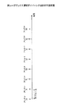
一例として、アンテナ#1とアンテナ#2の2本のアンテナを備えるユーザ装置において、データを送信するアンテナとしてアンテナ#1が選択されている場合について、図1を参照して説明する。このようなユーザ装置では、例えばサブフレーム毎にリファレンスシグナル(サウンディングリファレンスシグナル)が送信されるが、予め決定された所定の周期で、リファレンスシグナルを送信するアンテナが切り替えられる、例えば4サブフレームに1回リファレンスシグナルを送信するアンテナが切り替えられる。すなわち、4サブフレームのうち3サブフレームではデータ送信用に割り当てられたアンテナからサウンディングリファレンスシグナルが送信され、1サブフレームではデータ送信用に割り当てられていないアンテナからサウンディングリファレンスシグナルが送信される。
As an example, a case where
サウンディングリファレンスシグナルは、データを送信するアンテナとして選択されたアンテナにおける周波数スケジューリングに使用される。したがって、データを送信するアンテナとして選択されたアンテナから送信されるサウンディングリファレンスシグナルの送信回数を減少させるとスケジューリングの精度が悪くなる。一方、データを送信するアンテナとして選択されていないアンテナ#2からのサウンディングリファレンスシグナルの送信回数を減少させるとアンテナの切り替え回数が減少し、特にフェージング周期が短く、アンテナの切り替えを頻繁に行う必要がある場合に通信の品質が悪くなる。
The sounding reference signal is used for frequency scheduling at the antenna selected as the antenna to transmit data. Therefore, if the number of transmissions of the sounding reference signal transmitted from the antenna selected as the antenna for transmitting data is decreased, the scheduling accuracy is deteriorated. On the other hand, if the number of transmissions of the sounding reference signal from
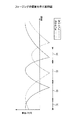
例えば、図2に示すようにフェージング周期が短い場合には、頻繁に受信品質のよいアンテナが入れ替わる。時間間隔(1)ではアンテナ#1の受信品質がよく、時間間隔(2)ではアンテナ#2の受信品質がよく、時間間隔(3)ではアンテナ#1の受信品質がよく、時間間隔(4)ではアンテナ#2の受信品質がよい。この場合、データを送信するアンテナとして選択されていないアンテナ#2からのサウンディングリファレンスシグナルの送信回数が減少すると、受信品質がよくない時間間隔でもデータを送信するアンテナとして選択されているアンテナ#1から送信され続けられることになるため好ましくない。
For example, when the fading period is short as shown in FIG. 2, antennas with good reception quality are frequently switched. The reception quality of
一方、図3に示すようにフェージング周期が長い場合には、受信品質のよいアンテナが入れ替わる頻度は少なくなる。時間間隔(1)ではアンテナ#1の受信品質がよく、時間間隔(2)ではアンテナ#2の受信品質がよい。この場合、データを送信するアンテナとして選択されていないアンテナ#2からのサウンディングリファレンスシグナルの送信回数が減少しても、受信品質の変動が小さく、データを送信するアンテナの切替えが生じる回数は少ないため、問題は少ない。
On the other hand, as shown in FIG. 3, when the fading period is long, the frequency with which antennas with good reception quality are switched decreases. The reception quality of
本発明は上述した従来技術の問題点を解決するためになされたものであり、その目的は、送信ダイバーシチが適用される移動通信システムにおいて、リファレンスシグナルを送信するアンテナを切替える周期を適切に制御できる基地局装置及びユーザ装置並びに通信制御方法を提供することにある。 The present invention has been made to solve the above-described problems of the prior art, and an object of the present invention is to appropriately control a cycle for switching an antenna that transmits a reference signal in a mobile communication system to which transmission diversity is applied. A base station apparatus, a user apparatus, and a communication control method are provided.
本ユーザ装置は、
複数のブロックが時間方向に配置されることによってサブフレームが形成された上りリンクにおいて送信ダイバーシチを適用する無線通信システムにおけるユーザ装置であって、
複数のアンテナと、
サブフレームを形成する複数のブロックのうちのひとつに配置されたサウンディングリファレンスシグナルを送信するためにアンテナを切替えるとともに、サウンディングリファレンスシグナルを配置させたブロックとは別のブロックに配置された共有データチャネルを送信するためにアンテナを切替えるアンテナ切替え部とを備え、
前記アンテナ切替え部は、共有データチャネルの送信用に選択されているアンテナに関わらず、サウンディングリファレンスシグナルを送信するために、基地局装置から指示された伝搬環境に応じた切替え周期にしたがって、連続して交互にアンテナを選択する。
This user device
A user apparatus in a wireless communication system that applies transmission diversity in an uplink in which a subframe is formed by arranging a plurality of blocks in a time direction,
Multiple antennas,
The antenna is switched to transmit a sounding reference signal arranged in one of a plurality of blocks forming a subframe, and a shared data channel arranged in a block different from the block in which the sounding reference signal is arranged An antenna switching unit that switches the antenna to transmit,
Regardless of the antenna selected for transmission of the shared data channel, the antenna switching unit continuously transmits a sounding reference signal according to a switching period in accordance with the propagation environment instructed by the base station apparatus. Select antennas alternately.
本送信方法は、
複数のアンテナを備え、かつ複数のブロックが時間方向に配置されることによってサブフレームが形成された上りリンクにおいて送信ダイバーシチを適用する無線通信システムにおけるユーザ装置での送信方法であって、
サブフレームを形成する複数のブロックのうちのひとつに配置されたサウンディングリファレンスシグナルを送信するためにアンテナを切替えるとともに、サウンディングリファレンスシグナルを配置させたブロックとは別のブロックに配置された共有データチャネルを送信するためにアンテナを切替えるステップを備え、
前記切替えるステップは、共有データチャネルの送信用に選択されているアンテナに関わらず、サウンディングリファレンスシグナルを送信するために、基地局装置から指示された伝搬環境に応じた切替え周期にしたがって、連続して交互にアンテナを選択する。
This transmission method is
A transmission method in a user apparatus in a wireless communication system that includes a plurality of antennas and applies transmission diversity in an uplink in which a subframe is formed by arranging a plurality of blocks in a time direction,
The antenna is switched to transmit a sounding reference signal arranged in one of a plurality of blocks forming a subframe, and a shared data channel arranged in a block different from the block in which the sounding reference signal is arranged Comprising switching antennas for transmission,
The switching step is performed continuously according to a switching period corresponding to a propagation environment instructed by the base station apparatus to transmit a sounding reference signal regardless of an antenna selected for transmission of a shared data channel. Select antennas alternately.
本無線通信システムは、
複数のブロックが時間方向に配置されることによってサブフレームが形成された上りリンクにおいて送信ダイバーシチを適用した信号を送信するユーザ装置と、
前記ユーザ装置からの上りリンクの信号を受信する基地局装置とを備え、
前記ユーザ装置は、
複数のアンテナと、
サブフレームを形成する複数のブロックのうちのひとつに配置されたサウンディングリファレンスシグナルを送信するためにアンテナを切替えるとともに、サウンディングリファレンスシグナルを配置させたブロックとは別のブロックに配置された共有データチャネルを送信するためにアンテナを切替えるアンテナ切替え部とを備え、
前記アンテナ切替え部は、共有データチャネルの送信用に選択されているアンテナに関わらず、サウンディングリファレンスシグナルを送信するために、基地局装置から指示された伝搬環境に応じた切替え周期にしたがって、連続して交互にアンテナを選択する。
This wireless communication system
A user apparatus that transmits a signal to which transmission diversity is applied in an uplink in which a subframe is formed by arranging a plurality of blocks in the time direction;
A base station apparatus that receives an uplink signal from the user apparatus,
The user equipment is
Multiple antennas,
The antenna is switched to transmit a sounding reference signal arranged in one of a plurality of blocks forming a subframe, and a shared data channel arranged in a block different from the block in which the sounding reference signal is arranged An antenna switching unit that switches the antenna to transmit,
Regardless of the antenna selected for transmission of the shared data channel, the antenna switching unit continuously transmits a sounding reference signal according to a switching period in accordance with the propagation environment instructed by the base station apparatus. Select antennas alternately.
本発明の実施例によれば、送信ダイバーシチが適用される移動通信システムにおいて、リファレンスシグナルを送信するアンテナを切替える周期を適切に制御できる基地局装置及びユーザ装置並びに通信制御方法を実現できる。 According to the embodiment of the present invention, in a mobile communication system to which transmission diversity is applied, it is possible to realize a base station apparatus, a user apparatus, and a communication control method that can appropriately control a cycle for switching an antenna that transmits a reference signal.
次に、本発明を実施するための最良の形態を、以下の実施例に基づき図面を参照しつつ説明する。
尚、実施例を説明するための全図において、同一機能を有するものは同一符号を用い、繰り返しの説明は省略する。
Next, the best mode for carrying out the present invention will be described based on the following embodiments with reference to the drawings.
In all the drawings for explaining the embodiments, the same reference numerals are used for those having the same function, and repeated explanation is omitted.
本発明の実施例に係る基地局装置が適用される無線通信システムについて、図4を参照して説明する。 A radio communication system to which a base station apparatus according to an embodiment of the present invention is applied will be described with reference to FIG.
無線通信システム1000は、例えばEvolved UTRA and UTRAN(別名:LTE(Long Term Evolution),或いは,Super 3G)が適用されるシステムであり、基地局装置(eNB:eNode B)200と複数のユーザ装置(UE:User Equipment)100n(1001、1002、1003、・・・100n、nはn>0の整数)とを備える。基地局装置200は、上位局、例えばアクセスゲートウェイ装置300と接続され、アクセスゲートウェイ装置300は、コアネットワーク400と接続される。ここで、ユーザ装置100nはセル50において基地局装置200とEvolved UTRA and UTRANにより通信を行う。
The
以下、ユーザ装置100n(1001、1002、1003、・・・100n)については、同一の構成、機能、状態を有するので、以下では特段の断りがない限りユーザ装置100nとして説明を進める。
Hereinafter, since the user apparatus 100 n (100 1 , 100 2 , 100 3 ,... 100 n ) has the same configuration, function, and state, the following description will be given as the
無線通信システム1000は、無線アクセス方式として、下りリンクについてはOFDM(周波数分割多元接続)、上りリンクについてはSC−FDMA(シングルキャリア−周波数分割多元接続)が適用される。上述したように、OFDMは、周波数帯域を複数の狭い周波数帯域(サブキャリア)に分割し、各周波数帯上にデータを載せて伝送を行う方式である。SC−FDMAは、周波数帯域を分割し、複数の端末間で異なる周波数帯域を用いて伝送することで、端末間の干渉を低減することができる伝送方式である。
ここで、LTEにおける通信チャネルについて説明する。 Here, a communication channel in LTE will be described.
下りリンクについては、各ユーザ装置100nで共有して使用される下り共有物理チャネル(PDSCH: Physical Downlink Shared Channel)と、LTE用の下り制御チャネルとが用いられる。下りリンクでは、LTE用の下り制御チャネルにより、下り共有物理チャネルにマッピングされるユーザの情報やトランスポートフォーマットの情報、上り共有物理チャネルにマッピングされるユーザの情報やトランスポートフォーマットの情報、上り共有物理チャネルの送達確認情報などが通知され、下り共有物理チャネルによりユーザデータが伝送される。
For the downlink, a downlink shared physical channel (PDSCH) shared by each
上りリンクについては、各ユーザ装置100nで共有して使用される上り共有物理チャネル(PUSCH: Physical Uplink Shared Channel)と、LTE用の上り制御チャネルとが用いられる。尚、上り制御チャネルには、上り共有物理チャネルと時間多重されるチャネルと、周波数多重されるチャネルの2種類がある。
For the uplink, an uplink shared physical channel (PUSCH) shared by each
上りリンクでは、LTE用の上り制御チャネルにより、下りリンクにおける共有物理チャネルのスケジューリング、適応変復調・符号化(AMC: Adaptive Modulation and Coding)、送信電力制御(TPC: Transmit Power Control)に用いるための下りリンクの品質情報(CQI: Channel Quality Indicator)及び下りリンクの共有物理チャネルの送達確認情報(HARQ ACK information)が伝送される。また、上り共有物理チャネルによりユーザデータが伝送される。 In the uplink, the downlink control channel is used for scheduling of the shared physical channel in the downlink, adaptive modulation and coding (AMC), transmission power control (TPC: Transmit Power Control) by the uplink control channel for LTE. Link quality information (CQI: Channel Quality Indicator) and downlink shared physical channel acknowledgment information (HARQ ACK information) are transmitted. Also, user data is transmitted through the uplink shared physical channel.
上りリンク伝送では、タイムスロットとしての1サブフレーム当たり7個のロングブロック(LB: Long Block)を用いることが検討されている。そして、1TTI(Transmit Time Interval)は、2サブフレームで構成される。すなわち、1TTIは、図5に示すように、14個のロングブロックにより構成される。上記14個のロングブロックの内の2個のロングブロックには、データ復調用のリファレンス信号(デモジュレーションリファレンスシグナル)(Demodulation Reference Signal)がマッピングされる。また、上記14個の内の、上述したDemodulation Reference Signalがマッピングされているロングブロック以外の1つのロングブロックにおいて、スケジューリングや上りリンクのAMC、TPCなど上り共有物理チャネルの送信フォーマットの決定に用いられるサウンディング用のリファレンス信号(サウンディングリファレンスシグナル)(Sounding Reference Signal)が送信される。 In uplink transmission, use of seven long blocks (LBs) per subframe as time slots is being studied. One TTI (Transmit Time Interval) is composed of two subframes. That is, 1 TTI is composed of 14 long blocks as shown in FIG. A reference signal (demodulation reference signal) for data demodulation is mapped to two long blocks among the 14 long blocks. Of the 14 blocks, one long block other than the long block to which the above-described Demodulation Reference Signal is mapped is used for scheduling and determining the transmission format of the uplink shared physical channel such as uplink AMC and TPC. A sounding reference signal (Sounding Reference Signal) is transmitted.
上記Sounding Reference Signalが送信されるロングブロックにおいては、符号分割多重(CDM: Code Division Multiplexing)により複数のユーザ装置からのSounding Reference Signalが多重される。上記Demodulation Reference Signalは、例えば、1TTI内の4番目のロングブロックと11番目のロングブロックにマッピングされる。また、上記Sounding Reference Signalは、例えば、1TTI内の1番目のロングブロックにマッピングされる。 In the long block in which the sounding reference signal is transmitted, sounding reference signals from a plurality of user apparatuses are multiplexed by code division multiplexing (CDM). The above-mentioned Demodulation Reference Signal is mapped to, for example, the fourth long block and the eleventh long block in 1 TTI. The Sounding Reference Signal is mapped to the first long block in 1 TTI, for example.
あるいは、上りリンクにおける伝送フォーマットとして、各サブフレーム当たり2個のショートブロック(SB: Short Block)と6個のロングブロックを用いることも検討されている。そして、1TTIは、2サブフレームで構成される。すなわち、1TTIは、図6に示すように、4個のショートブロックと12個のロングブロックにより構成される。上記12個のロングブロックの内の1個のロングブロックには、Sounding Reference Signal)がマッピングされる。上記Sounding Reference Signalが送信されるロングブロックにおいては、CDMにより複数のユーザ装置からのSounding Reference Signalが多重される。 Alternatively, the use of two short blocks (SB) and six long blocks for each subframe as an uplink transmission format is also under consideration. One TTI is composed of two subframes. That is, as shown in FIG. 6, 1 TTI is composed of 4 short blocks and 12 long blocks. Sounding Reference Signal (Sound Reference Signal) is mapped to one of the 12 long blocks. In the long block in which the sounding reference signal is transmitted, sounding reference signals from a plurality of user apparatuses are multiplexed by the CDM.
4個のショートブロックは、Demodulation Reference Signalの伝送に使用される。上記Demodulation Reference Signalは、例えば、1TTI内の4個のショートブロックにマッピングされる。また、上記Sounding Reference Signalは、例えば、1TTI内の1番目のロングブロックにマッピングされる。 Four short blocks are used for transmission of the Demodulation Reference Signal. The Demodulation Reference Signal is mapped to, for example, four short blocks in 1 TTI. The Sounding Reference Signal is mapped to the first long block in 1 TTI, for example.
上りリンクにおいて、各ユーザ装置100nは、周波数方向はRB(Resource Block: リソースブロック)単位、時間方向はTTI単位でデータ送信を行う。LTEにおいては、1RBは180kHzである。
In the uplink, each
また、上りリンクにおいて、各ユーザ装置100nは、複数のRBに渡ってSounding Reference Signalを送信する。
In the uplink, each
次に、本発明の実施例に係る基地局装置200について、図7を参照して説明する。
Next, the
本実施例に係る基地局装置200は、ユーザ装置100nの移動速度に応じて切り替え周期を変更する。本実施例では、ユーザ装置100nの移動速度を示す指標としてフェージング周期を用いる場合について説明するが、他の指標を用いるようにしてもよい。ユーザ装置100nの移動速度が速くなるとフェージング変動が速くなりフェージング周期も短くなるので、より短い周期でアンテナ選択を行う必要がある。
The
また、本実施例では、閉ループ制御で追従できないほどユーザ装置100nが高速に移動する場合にはアンテナ選択周期を逆に極端に長くするか、閉ループアンテナ選択ダイバーシチを停止する構成をとる。このようにすることにより、無駄なリファレンス信号の送信を抑えることができる。
Further, in this embodiment, either extremely long antenna selection period conversely if that can not be followed in the closed-loop
本実施例に係る基地局装置200は、送受信アンテナ202と、送受共用部204と、受信RF部206と、リファレンスシグナル測定部208と、送信アンテナ切替周期決定部210と、記憶部212と、送信RF部214とを備える。
The
上りリンクによりユーザ装置100nから送信されるサウンディングリファレンスシグナルは、送受信アンテナ202及び送受共用部204を介して、受信RF部206において受信される。
The sounding reference signal transmitted from the
受信RF部206では、サウンディングリファレンスシグナルの受信処理が行われ、リファレンスシグナル測定部208に入力される。
The
リファレンスシグナル測定部208は、例えば受信されたサウンディングリファレンスシグナルに基づいて、その受信レベルを測定し、フェージング周期を求める。ここで、フェージング周期は、予め決定された所定の観測期間において、サウンディングリファレンスシグナルの受信レベルが、予め決定された所定の閾値以上となる回数を算出し、該回数に基づいて求められる。例えば、予め決定された所定の閾値が零である場合には、その零をクロスする回数が求められる。リファレンスシグナル測定部208は、測定したフェージング周期を送信アンテナ切替周期決定部210に入力する。
The reference
送信アンテナ切替周期決定部210は、入力されたフェージング周期に基づいて、記憶部212に記憶されたフェージング周期とサウンディングリファレンスシグナルを送信するアンテナを切替える周期との対応を示すテーブルを参照して、リファレンスシグナルを送信するアンテナを切替える周期を決定する。送信アンテナ切替周期決定部210は、決定されたリファレンスシグナルを送信するアンテナを切替える周期を、送信RF部214に入力する。送信RF部214は、入力されたリファレンスシグナルを送信するアンテナを切替える周期を、送受共用部204を介して送信する。例えば、送信RF部214は、下りチャネル、例えば、下りL1/L2制御チャネル又は専用の制御チャネルを使用してユーザ装置100nに通知する。
Based on the input fading cycle, the transmission antenna switching
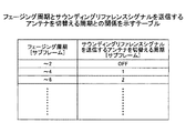
記憶部212には、図8に示すように、フェージング周期とサウンディングリファレンスシグナルを送信するアンテナを切替える周期との対応を示すテーブルが記憶される。このテーブルでは、移動速度が速いほど、すなわちフェージング周期が短いほど、送信間隔が短くなるように作成される。
As shown in FIG. 8, the
また、移動速度が予め定めた値、例えば当該閉ループ制御による追従ができなくなる速度よりも速くなったとき、サウンディングリファレンスシグナルを送信するアンテナを切替える周期を長くする。又は、アンテナ選択ダイバーシチを停止するようにしてもよい。例えば、当該閉ループ制御による追従ができなくなる速度に対応するフェージング周期未満、例えばフェージング周期が2サブフレーム未満となった場合にはサウンディングリファレンスシグナルを送信するアンテナを切替える周期を長くするか又はアンテナ選択ダイバーシチを停止する。 Further, when the moving speed becomes faster than a predetermined value, for example, a speed at which tracking by the closed-loop control cannot be performed, the cycle for switching the antenna that transmits the sounding reference signal is lengthened. Alternatively, antenna selection diversity may be stopped. For example, if the fading period is less than the fading period corresponding to the speed at which tracking cannot be performed by the closed loop control, for example, if the fading period is less than 2 subframes, the period for switching the antenna that transmits the sounding reference signal may be increased, or antenna selection diversity may be performed. To stop.
次に、本発明の実施例に係るユーザ装置100について、図9を参照して説明する。
Next, the
本実施例に係るユーザ装置100は、SC−FDMA変調部102と、RF送信回路104と、パワーアンプ(PA:Power Amplifier)106と、送信アンテナ切替部108と、アンテナ110と、アンテナ112とを備える。送信アンテナ切替部108には、基地局装置200により送信されたリファレンスシグナルを送信するアンテナを切替える周期(リファレンスシグナル切替え周期)が入力される。
The
ベースバンド処理されたサウンディングリファレンスシグナルは、SC−FDMA変調部102に入力され、SC−FDMA方式の変調処理が行われ、RF送信回路104に入力される。
The sounding reference signal subjected to the baseband processing is input to the SC-
RF送信回路104は、変調処理が行われたサウンディングリファレンスシグナルを、設定された上りリンクの送信周波数帯に応じたRF周波数に変換する。RF変換された信号は、PA106で増幅される。
The
PA106で増幅された信号は、送信アンテナ切替部108において、基地局装置200から通知されたリファレンスシグナル切替周期に基づいて切替えられたアンテナにより送信される。
The signal amplified by
例えば、図10に示すように、基地局装置200から送信されたリファレンスシグナル切替え周期にしたがって、共有データチャネルの送信用に選択されているアンテナにかかわらず、決められた順序で交互にリファレンス信号が送信される。図10には、サウンディングリファレンスシグナルを送信するアンテナが、1サブフレーム毎に切替えられる場合を示す。
For example, as shown in FIG. 10, according to the reference signal switching period transmitted from the
具体的には、送信アンテナ切替部108は、リファレンスシグナル切替周期に基づいて、サブフレームを示す番号をリファレンスシグナル切替周期で割った余りに基づいて、データ送信用に割り当てられたアンテナでサウンディングリファレンスシグナルを送信するか否かを判断する。
Specifically, based on the reference signal switching period, the transmission
例えば、リファレンスシグナル切替周期として4[サブフレーム]が通知され、余りが0、1及び2の場合にはデータ送信用に割り当てられたアンテナでサウンディングリファレンスシグナルを送信することが決定され、余りが3の場合にはデータ送信用に割り当てられていないアンテナでサウンディングリファレンスシグナルを送信することが決定される場合について説明する。 For example, 4 [subframe] is notified as the reference signal switching period, and when the remainder is 0, 1 and 2, it is determined that the sounding reference signal is transmitted by the antenna allocated for data transmission, and the remainder is 3 In the case of, a case will be described in which it is determined to transmit a sounding reference signal with an antenna not assigned for data transmission.
この場合、サブフレーム#1及び#2では、データ送信用に割り当てられたアンテナでサウンディングリファレンスシグナルが送信され、サブフレーム#3では、データ送信用に割り当てられていないアンテナでサウンディングリファレンスシグナルが送信され、サブフレーム#4では、データ送信用に割り当てられているアンテナでサウンディングリファレンスシグナルが送信される。例えば、データ送信用にアンテナ#1が割り当てられ、サブフレーム#3でデータ送信用としてアンテナ#2が割り当てられた場合には、サブフレーム#4ではデータ送信用として割り当てられているアンテナ#2によりサウンディングリファレンスシグナルが送信される。
In this case, in
このようにすることにより、リファレンス信号を送信するアンテナの切り替えパターン、すなわちリファレンスシグナルを送信するアンテナを切替える周期さえ送受信機間、すなわち基地局装置200−ユーザ装置間で分かっていれば、送信を制御するのに追加の制御情報を不要にできる。
By doing this, if the switching pattern of the antenna for transmitting the reference signal, that is, the period for switching the antenna for transmitting the reference signal is known between the transceiver, that is, between the
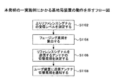
次に、本実施例に係る無線通信システム1000における基地局装置200の動作について、図11を参照して説明する。リファレンスシグナル測定部208は、ユーザ装置100nから送信されたリファレンスシグナル(サウンディングリファレンスシグナル)の受信レベル、例えばCQIを測定する(ステップS1102)。
Next, the operation of the
次に、リファレンスシグナル測定部208は、測定されたサウンディングリファレンスシグナルの受信レベルに基づいて、フェージング周期を算出する(ステップS1104)。例えば、リファレンスシグナル測定部208は、グリファレンスシグナルの受信レベルが、予め決定された所定の観測期間において、予め決定された所定の閾値以上となる回数を算出し、フェージング周期を求める。
Next, the reference
次に、送信アンテナ切替え周期決定部210は、フェージング周期に基づいて、リファレンスシグナルを送信するアンテナの切替え周期を決定する(ステップS1106)。
Next, the transmission antenna switching
次に、送信アンテナ切替え周期決定部210は、決定されたリファレンスシグナルを送信するアンテナの切替え周期を、送信RF部214を介してユーザ装置100nに通知する(ステップS1108)。
Next, the transmission antenna switching
次に、本発明の他の実施例に係る無線通信システムについて説明する。 Next, a radio communication system according to another embodiment of the present invention will be described.
本実施例に係る無線通信システム、基地局装置及びユーザ装置の構成は、図4、図7及び図9を参照して説明した構成と同様であるため、その説明を省略する。 The configurations of the radio communication system, the base station apparatus, and the user apparatus according to the present embodiment are the same as the configurations described with reference to FIGS. 4, 7, and 9, and thus description thereof is omitted.
本実施例に係る基地局装置200は、ユーザ装置100nの位置に応じて、リファレンスシグナルを送信するアンテナを切替える周期を変更する。例えば、ユーザ装置100nがセル端に位置すると判断される状況ほど、切り替える周期が短くなるように決定する。セル端に位置するユーザ装置100nほど送信ダイバーシチ効果が必要である。したがって、このようなユーザ装置100nに対する切り替え周期を短くすることにより、大きなダイバーシチ効果を得られるようにできる。一方、セル中心に近い領域に位置するユーザ装置100nに対しては切り替え周期を長くするか、閉ループアンテナ選択ダイバーシチを停止する。
The
本実施例に係る基地局装置200では、リファレンスシグナル測定部208において、リファレンスシグナルの受信強度(受信レベル)を測定し、送信アンテナ切替え周期決定部210に入力する。
In the
送信アンテナ切替え周期決定部210は、入力されたリファレンスシグナルの受信強度に基づいて、記憶部212に記憶されたリファレンスシグナルの受信強度とサウンディングリファレンスシグナルを送信するアンテナを切替える周期との対応を示すテーブルを参照して、送信アンテナの切替え周期を決定する。送信アンテナ切替え周期決定部210は、決定された送信アンテナの切替え周期を、送信RF部214に入力する。送信RF部214は、入力された送信アンテナの切替え周期を、送受共用部204を介して送信する。例えば、送信RF部214は、下りチャネル、例えば、下りL1/L2制御チャネル又は専用の制御チャネルを使用してユーザ装置100nに通知する。
The transmission antenna switching
記憶部212には、図12に示すように、リファレンスシグナルの受信強度とサウンディングリファレンスシグナルを送信するアンテナを切替える周期との対応を示すテーブルが記憶される。このテーブルでは、リファレンスシグナルの受信強度が低いほど、ユーザ装置100nはセル端に近い領域に位置すると判断されるため、アンテナを切替える周期が短くなるように作成される。一方、リファレンスシグナルの受信強度が高いほど、ユーザ装置100nはセル中心に近い領域位置すると判断されるため、アンテナを切替える周期が長くなるように作成される。
As shown in FIG. 12, the
また、リファレンスシグナルの受信強度が予め定めた値よりも低くなったとき、例えば当該閉ループ制御による追従ができなくなる場合のアンテナを切替える周期に対応する受信強度よりも低くなったとき(閉ループ制御による追従ができなくなる場合のアンテナを切替える周期に対応する受信強度未満となったとき)には、リファレンスシグナルを送信するアンテナを切替える周期を長くする。又はアンテナ選択ダイバーシチを停止するようにしてもよい。 In addition, when the reception strength of the reference signal is lower than a predetermined value, for example, when the reception strength is lower than the reception strength corresponding to the period of switching the antenna when the tracking by the closed loop control becomes impossible (following by the closed loop control) When the received intensity is less than the reception intensity corresponding to the period for switching the antenna when the antenna cannot be changed), the period for switching the antenna for transmitting the reference signal is lengthened. Alternatively, antenna selection diversity may be stopped.
次に、本実施例に係る無線通信システム1000における基地局装置200の動作について、図13を参照して説明する。リファレンスシグナル測定部208は、ユーザ装置100nから送信されたリファレンスシグナルの受信強度(受信レベル)を測定する(ステップS1302)。
Next, the operation of the
次に、送信アンテナ切替え周期決定部210は、リファレンスシグナルの受信強度に基づいて、リファレンスシグナルを送信するアンテナの切替え周期を決定する(ステップS1304)。
Next, the transmission antenna switching
次に、送信アンテナ切替え周期決定部210は、決定されたリファレンスシグナルを送信するアンテナの切替え周期を、送信RF部214を介してユーザ装置100nに通知する(ステップS1306)。
Next, the transmission antenna switching
本実施例においては、ユーザ装置100nから受信される上りリファレンス信号により、ユーザ装置100nのセル内での位置を感知する場合について説明したが、共有データチャネル受信信号強度の測定結果、送信電力制御(TPC: Transmit Power Control)コマンドの値などにより、ユーザ装置100nのセル内での位置を感知するようにしてもよい。
In this embodiment, the uplink reference signal received from the
上述した実施例においては、基地局装置200が、ユーザ装置100nから受信される上りリファレンス信号から当該ユーザ装置100nの移動速度を感知し、予め用意した変換テーブルによりリファレンスシグナルを送信するアンテナを切替える周期(送信パターン)へ変換する場合について説明した。
In the embodiment described above, the
また、基地局装置200が、ユーザ装置100nから受信される上りリファレンス信号及び/又は共有データチャネル受信信号強度の測定、送信電力制御(TPC: Transmit Power Control)コマンドの値などにより、ユーザ装置100nのセル内での位置を感知し、予め用意した変換テーブルによりリファレンスシグナルを送信するアンテナを切替える周期(送信パターン)へ変換する場合について説明した。
Further, the
このように、基地局装置200側でリファレンスシグナルを送信するアンテナを切替える周期を決定するのではなく、ユーザ装置100nが自ユーザ装置100nの移動速度及び/又は自ユーザ装置100nのセル内での位置を感知し、予め用意した変換テーブルによりリファレンスシグナルを送信するアンテナを切替える周期(送信パターン)へ変換するようにしてもよい。例えば、ユーザ装置100nは、下りリファレンス信号から推定されるフェージング変動速度、ユーザ装置100nに搭載されたGPS(Global Positioning System)により推定される移動速度などに基づいて、移動速度を感知することができる。また、例えば、ユーザ装置100nは、接続している基地局装置200からのパスロスまたは接続している基地局装置200のパスロスと該基地局装置に隣接している(周辺の)基地局装置のパスロス比の測定、GPSにより得られる地理情報と予め搭載された基地局装置の位置情報との照合、TPCコマンドの値などにより、自ユーザ装置100nのセル内での位置を感知することができる。
Thus, instead of determining the period for switching the antenna for transmitting a reference signal in the
このように、ユーザ装置100nが送信間隔を決定する場合、その決定結果は上りチャネル、上り個別制御チャネルにより基地局装置200に通知される。
Thus, when the
50 セル
1001、1002、1003、100n ユーザ装置
102 SC−FDMA変調部
104 RF送信回路
106 パワーアンプ(PA: Power Amplifier)
108 送信アンテナ切替部
110、112 アンテナ
200 基地局装置
202 送受信アンテナ
204 送受共用部
206 受信RF部
208 リファレンスシグナル測定部
210 送信アンテナ切替周期決定部
212 記憶部
214 送信RF部
300 アクセスゲートウェイ装置
400 コアネットワーク
1000 無線通信システム
50
108 Transmitting
Claims (3)
複数のアンテナと、
サブフレームを形成する複数のブロックのうちのひとつに配置されたサウンディングリファレンスシグナルを送信するためにアンテナを切替えるとともに、サウンディングリファレンスシグナルを配置させたブロックとは別のブロックに配置された共有データチャネルを送信するためにアンテナを切替えるアンテナ切替え部とを備え、
前記アンテナ切替え部は、共有データチャネルの送信用に選択されているアンテナに関わらず、サウンディングリファレンスシグナルを送信するために、基地局装置から指示された伝搬環境に応じた切替え周期にしたがって、連続して交互にアンテナを選択することを特徴とするユーザ装置。 A user apparatus in a wireless communication system that applies transmission diversity in an uplink in which a subframe is formed by arranging a plurality of blocks in a time direction,
Multiple antennas,
The antenna is switched to transmit a sounding reference signal arranged in one of a plurality of blocks forming a subframe, and a shared data channel arranged in a block different from the block in which the sounding reference signal is arranged An antenna switching unit that switches the antenna to transmit,
Regardless of the antenna selected for transmission of the shared data channel, the antenna switching unit continuously transmits a sounding reference signal according to a switching period in accordance with the propagation environment instructed by the base station apparatus. A user apparatus characterized by alternately selecting an antenna.
サブフレームを形成する複数のブロックのうちのひとつに配置されたサウンディングリファレンスシグナルを送信するためにアンテナを切替えるとともに、サウンディングリファレンスシグナルを配置させたブロックとは別のブロックに配置された共有データチャネルを送信するためにアンテナを切替えるステップを備え、
前記切替えるステップは、共有データチャネルの送信用に選択されているアンテナに関わらず、サウンディングリファレンスシグナルを送信するために、基地局装置から指示された伝搬環境に応じた切替え周期にしたがって、連続して交互にアンテナを選択することを特徴とする送信方法。 A transmission method in a user apparatus in a wireless communication system that includes a plurality of antennas and applies transmission diversity in an uplink in which a subframe is formed by arranging a plurality of blocks in a time direction,
The antenna is switched to transmit a sounding reference signal arranged in one of a plurality of blocks forming a subframe, and a shared data channel arranged in a block different from the block in which the sounding reference signal is arranged Comprising switching antennas for transmission,
The switching step is performed continuously according to a switching period corresponding to a propagation environment instructed by the base station apparatus to transmit a sounding reference signal regardless of an antenna selected for transmission of a shared data channel. A transmission method characterized by alternately selecting antennas.
前記ユーザ装置からの上りリンクの信号を受信する基地局装置とを備え、
前記ユーザ装置は、
複数のアンテナと、
サブフレームを形成する複数のブロックのうちのひとつに配置されたサウンディングリファレンスシグナルを送信するためにアンテナを切替えるとともに、サウンディングリファレンスシグナルを配置させたブロックとは別のブロックに配置された共有データチャネルを送信するためにアンテナを切替えるアンテナ切替え部とを備え、
前記アンテナ切替え部は、共有データチャネルの送信用に選択されているアンテナに関わらず、サウンディングリファレンスシグナルを送信するために、基地局装置から指示された伝搬環境に応じた切替え周期にしたがって、連続して交互にアンテナを選択することを特徴とする無線通信システム。 A user apparatus that transmits a signal to which transmission diversity is applied in an uplink in which a subframe is formed by arranging a plurality of blocks in the time direction;
A base station apparatus that receives an uplink signal from the user apparatus,
The user equipment is
Multiple antennas,
The antenna is switched to transmit a sounding reference signal arranged in one of a plurality of blocks forming a subframe, and a shared data channel arranged in a block different from the block in which the sounding reference signal is arranged An antenna switching unit that switches the antenna to transmit,
Regardless of the antenna selected for transmission of the shared data channel, the antenna switching unit continuously transmits a sounding reference signal according to a switching period in accordance with the propagation environment instructed by the base station apparatus. A radio communication system, wherein antennas are alternately selected.
Priority Applications (11)
| Application Number | Priority Date | Filing Date | Title |
|---|---|---|---|
| JP2007034133A JP4869972B2 (en) | 2007-02-14 | 2007-02-14 | User apparatus, transmission method, and wireless communication system |
| PCT/JP2008/052137 WO2008099780A1 (en) | 2007-02-14 | 2008-02-08 | Base station device, user device, and communication control method |
| RU2009133104/07A RU2456744C2 (en) | 2007-02-14 | 2008-02-08 | Basic station, user device and method of communication control |
| EP08711016.9A EP2129005A4 (en) | 2007-02-14 | 2008-02-08 | Base station device, user device, and communication control method |
| BRPI0808128-0A2A BRPI0808128A2 (en) | 2007-02-14 | 2008-02-08 | BASE STATION DEVICE, USER APPARATUS AND COMMUNICATION CONTROL METHOD |
| US12/526,729 US8463203B2 (en) | 2007-02-14 | 2008-02-08 | Base station apparatus, user apparatus and communication control method |
| EP13186821.8A EP2683096B1 (en) | 2007-02-14 | 2008-02-08 | Base station apparatus, user apparatus and communication control method |
| CN201310424721.0A CN103763013B (en) | 2007-02-14 | 2008-02-08 | Base station apparatus and receiving method |
| KR1020097018796A KR101340379B1 (en) | 2007-02-14 | 2008-02-08 | Base station device, user device, and communication control method |
| CN2008800120504A CN101657979B (en) | 2007-02-14 | 2008-02-08 | Base station device, user device, and communication control method |
| US13/862,995 US9369996B2 (en) | 2007-02-14 | 2013-04-15 | Base station apparatus, user apparatus and communication control method |
Applications Claiming Priority (1)
| Application Number | Priority Date | Filing Date | Title |
|---|---|---|---|
| JP2007034133A JP4869972B2 (en) | 2007-02-14 | 2007-02-14 | User apparatus, transmission method, and wireless communication system |
Related Child Applications (1)
| Application Number | Title | Priority Date | Filing Date |
|---|---|---|---|
| JP2010194603A Division JP5133383B2 (en) | 2010-08-31 | 2010-08-31 | Base station apparatus and reception method |
Publications (3)
| Publication Number | Publication Date |
|---|---|
| JP2008199424A JP2008199424A (en) | 2008-08-28 |
| JP2008199424A5 JP2008199424A5 (en) | 2010-10-14 |
| JP4869972B2 true JP4869972B2 (en) | 2012-02-08 |
Family
ID=39690013
Family Applications (1)
| Application Number | Title | Priority Date | Filing Date |
|---|---|---|---|
| JP2007034133A Expired - Fee Related JP4869972B2 (en) | 2007-02-14 | 2007-02-14 | User apparatus, transmission method, and wireless communication system |
Country Status (8)
| Country | Link |
|---|---|
| US (2) | US8463203B2 (en) |
| EP (2) | EP2129005A4 (en) |
| JP (1) | JP4869972B2 (en) |
| KR (1) | KR101340379B1 (en) |
| CN (2) | CN103763013B (en) |
| BR (1) | BRPI0808128A2 (en) |
| RU (1) | RU2456744C2 (en) |
| WO (1) | WO2008099780A1 (en) |
Families Citing this family (21)
| Publication number | Priority date | Publication date | Assignee | Title |
|---|---|---|---|---|
| US8077593B2 (en) * | 2007-08-08 | 2011-12-13 | Panasonic Corporation | Radio communication mobile station device and correlation setting method |
| EP2242304A4 (en) * | 2008-02-05 | 2014-06-11 | Sharp Kk | Mobile communication device, base station device, wireless control method, and mobile communication system |
| MX2010013250A (en) * | 2008-06-06 | 2010-12-21 | Sharp Kk | Mobile communication system, mobile communication device, and mobile communication method. |
| HUE038339T2 (en) * | 2008-06-23 | 2018-10-29 | Sun Patent Trust | Method of arranging reference signals and wireless communication base station apparatus |
| US8811513B2 (en) * | 2010-02-05 | 2014-08-19 | Qualcomm Incorporated | Antenna switching in a closed loop transmit diversity system |
| JP5291664B2 (en) * | 2010-04-30 | 2013-09-18 | 株式会社エヌ・ティ・ティ・ドコモ | Data transmission method, base station apparatus and mobile station apparatus |
| US8891387B2 (en) * | 2010-05-03 | 2014-11-18 | Qualcomm Incorporated | UE based conditional enabling of ULTD |
| JP5574872B2 (en) * | 2010-08-03 | 2014-08-20 | シャープ株式会社 | Base station apparatus, mobile station apparatus, and communication method |
| US8416741B2 (en) * | 2010-09-07 | 2013-04-09 | Verizon Patent And Licensing Inc. | Machine-to-machine communications over fixed wireless networks |
| EP2673909B1 (en) * | 2011-02-07 | 2019-02-27 | Telefonaktiebolaget LM Ericsson (publ) | Base station (antenna) selection for receiving uplink transmissions of sounding reference signals, srs, signals from a user equipment, ue |
| WO2012153994A2 (en) * | 2011-05-10 | 2012-11-15 | 엘지전자 주식회사 | Method for transmitting signal using plurality of antenna ports and transmission end apparatus for same |
| US9379789B2 (en) * | 2013-07-03 | 2016-06-28 | Qualcomm Incorporated | Antenna selection adjustment |
| KR102246558B1 (en) | 2014-02-28 | 2021-04-30 | 엘지전자 주식회사 | Method and apparatus for generating signal for low latency in wireless communication system |
| MY190449A (en) * | 2014-06-24 | 2022-04-21 | Ericsson Telefon Ab L M | Method and apparatuses for operating a wireless communication network |
| RU2677646C1 (en) * | 2015-05-22 | 2019-01-18 | Фудзицу Лимитед | Method and device for configuring resource of support signal and communication system |
| EP3583813B1 (en) * | 2017-02-15 | 2021-04-07 | Telefonaktiebolaget LM Ericsson (PUBL) | Managing communication in a wireless communication network |
| US10320517B2 (en) | 2017-06-05 | 2019-06-11 | J3 Technology LLC | Switched transmit antennas with no feedback for multipath reduction |
| JP2021182655A (en) * | 2018-08-09 | 2021-11-25 | ソニーグループ株式会社 | Communication device, communication control method and storage medium |
| CN111405663A (en) * | 2019-01-03 | 2020-07-10 | 索尼公司 | Electronic device and method for wireless communication, computer-readable storage medium |
| EP3957099A1 (en) * | 2019-04-17 | 2022-02-23 | Telefonaktiebolaget LM Ericsson (publ) | Radio network node and method for reducing energy consumption in a wireless communications network |
| US11374633B2 (en) * | 2019-11-21 | 2022-06-28 | Qualcomm Incorporated | Low cost power efficient antenna switch diversity and cyclic delay diversity transceiver |
Family Cites Families (27)
| Publication number | Priority date | Publication date | Assignee | Title |
|---|---|---|---|---|
| JP2650297B2 (en) | 1988-01-30 | 1997-09-03 | ソニー株式会社 | Antenna switching method |
| US5541963A (en) * | 1993-12-01 | 1996-07-30 | Hitachi, Ltd. | Diversity receiving apparatus |
| JPH07162350A (en) | 1993-12-07 | 1995-06-23 | Hitachi Ltd | Diversity receiver |
| DE19546599C2 (en) * | 1995-12-13 | 1999-07-29 | Siemens Ag | Sending device |
| US5692019A (en) * | 1996-06-17 | 1997-11-25 | Motorola, Inc. | Communication device having antenna switch diversity, and method therefor |
| JPH11252614A (en) | 1998-03-05 | 1999-09-17 | Kokusai Electric Co Ltd | Communication system, base station device and mobile station device |
| KR20000002504A (en) | 1998-06-20 | 2000-01-15 | 윤종용 | Selective transmitting diversity device of mobile communication system and method thereof |
| JP3583304B2 (en) * | 1998-11-18 | 2004-11-04 | 松下電器産業株式会社 | Communication terminal device, base station device, and transmission antenna switching method |
| JP2001196928A (en) | 2000-01-13 | 2001-07-19 | Hitachi Ltd | Analog/digital conversion processing unit |
| FR2810456B1 (en) * | 2000-06-20 | 2005-02-11 | Mitsubishi Electric Inf Tech | RECONFIGURABLE ANTENNA DEVICE FOR TELECOMMUNICATION STATION |
| EP1303059B1 (en) * | 2001-10-09 | 2006-08-23 | Lucent Technologies Inc. | Method and apparatus for transmission diversity in wireless telecomunication systems providing antenna and/or polarisation hopping sequences |
| JP3796188B2 (en) | 2002-04-09 | 2006-07-12 | パナソニック モバイルコミュニケーションズ株式会社 | OFDM communication method and OFDM communication apparatus |
| CN1281084C (en) * | 2002-11-04 | 2006-10-18 | 中兴通讯股份有限公司 | Method and device for realtime antenna to select emission diversity |
| ATE328400T1 (en) * | 2003-03-19 | 2006-06-15 | Sony Ericsson Mobile Comm Ab | SWITCHABLE ANTENNA ARRANGEMENT |
| JP2004320528A (en) | 2003-04-17 | 2004-11-11 | Mitsubishi Electric Corp | Diversity receiver |
| KR20050032809A (en) * | 2003-10-02 | 2005-04-08 | 삼성전자주식회사 | Apparatus andmethod for beamforming in nb-tdd system |
| US7039370B2 (en) * | 2003-10-16 | 2006-05-02 | Flarion Technologies, Inc. | Methods and apparatus of providing transmit and/or receive diversity with multiple antennas in wireless communication systems |
| JP4396379B2 (en) * | 2004-04-23 | 2010-01-13 | 日本電気株式会社 | Receive diversity system and control method thereof |
| JP2006067237A (en) * | 2004-08-26 | 2006-03-09 | Sharp Corp | Radio transmitter and radio receiver |
| US20060111054A1 (en) * | 2004-11-22 | 2006-05-25 | Interdigital Technology Corporation | Method and system for selecting transmit antennas to reduce antenna correlation |
| US7573851B2 (en) * | 2004-12-07 | 2009-08-11 | Adaptix, Inc. | Method and system for switching antenna and channel assignments in broadband wireless networks |
| WO2006104029A1 (en) | 2005-03-28 | 2006-10-05 | Matsushita Electric Industrial Co., Ltd. | Receiving terminal |
| JP2006279450A (en) | 2005-03-29 | 2006-10-12 | Clarion Co Ltd | On-vehicle digital television receiver |
| JP4812357B2 (en) | 2005-07-29 | 2011-11-09 | 株式会社Suwaオプトロニクス | Small diameter camera |
| US8116412B1 (en) * | 2006-12-30 | 2012-02-14 | Rockstar Bidco, LP | Modulation division multiple access |
| US7697623B2 (en) * | 2007-01-05 | 2010-04-13 | Mitsubishi Electric Research Laboratories, Inc. | Method and system for switching antennas during transmission time intervals in OFDMA systems |
| CN101682918B (en) * | 2007-02-02 | 2012-12-26 | Lg电子株式会社 | Antenna switching method and method for transmitting and receiving signals for the same |
-
2007
- 2007-02-14 JP JP2007034133A patent/JP4869972B2/en not_active Expired - Fee Related
-
2008
- 2008-02-08 RU RU2009133104/07A patent/RU2456744C2/en not_active IP Right Cessation
- 2008-02-08 EP EP08711016.9A patent/EP2129005A4/en not_active Withdrawn
- 2008-02-08 EP EP13186821.8A patent/EP2683096B1/en active Active
- 2008-02-08 WO PCT/JP2008/052137 patent/WO2008099780A1/en active Application Filing
- 2008-02-08 BR BRPI0808128-0A2A patent/BRPI0808128A2/en not_active IP Right Cessation
- 2008-02-08 CN CN201310424721.0A patent/CN103763013B/en active Active
- 2008-02-08 CN CN2008800120504A patent/CN101657979B/en active Active
- 2008-02-08 US US12/526,729 patent/US8463203B2/en not_active Expired - Fee Related
- 2008-02-08 KR KR1020097018796A patent/KR101340379B1/en active IP Right Grant
-
2013
- 2013-04-15 US US13/862,995 patent/US9369996B2/en active Active
Also Published As
| Publication number | Publication date |
|---|---|
| EP2683096A1 (en) | 2014-01-08 |
| EP2683096B1 (en) | 2017-08-23 |
| US20130223415A1 (en) | 2013-08-29 |
| US8463203B2 (en) | 2013-06-11 |
| CN103763013B (en) | 2017-01-18 |
| BRPI0808128A2 (en) | 2014-06-17 |
| JP2008199424A (en) | 2008-08-28 |
| KR101340379B1 (en) | 2013-12-13 |
| CN101657979B (en) | 2013-10-30 |
| RU2456744C2 (en) | 2012-07-20 |
| EP2129005A4 (en) | 2013-12-11 |
| WO2008099780A1 (en) | 2008-08-21 |
| CN103763013A (en) | 2014-04-30 |
| US20100056074A1 (en) | 2010-03-04 |
| KR20090110871A (en) | 2009-10-22 |
| RU2009133104A (en) | 2011-03-20 |
| CN101657979A (en) | 2010-02-24 |
| US9369996B2 (en) | 2016-06-14 |
| EP2129005A1 (en) | 2009-12-02 |
Similar Documents
| Publication | Publication Date | Title |
|---|---|---|
| JP4869972B2 (en) | User apparatus, transmission method, and wireless communication system | |
| CN110603862B (en) | Method and apparatus for reporting power headroom | |
| JP5507456B2 (en) | Mobile communication system, base station, user apparatus, and communication method | |
| JP5026207B2 (en) | Base station apparatus, user apparatus, and communication control method | |
| US9762456B2 (en) | Access node, control node, and various methods for adapting a reporting period for a user equipment | |
| CN111466148A (en) | Method for transmitting channel state information in wireless communication system by terminal and terminal using the same | |
| CN109565315B (en) | Network node, terminal and method for transmitting and receiving reference signaling by using antenna array | |
| JP5516820B2 (en) | Wireless communication system, base station apparatus, and wireless communication path selection method | |
| JP4888661B2 (en) | Transmission control method for downlink packet communication and radio base station | |
| EP2408231A1 (en) | Wireless base station | |
| JP5133383B2 (en) | Base station apparatus and reception method | |
| EP4060905A1 (en) | Wireless communication device including antenna modules and operating method of wireless communication device | |
| KR101162210B1 (en) | Method of switching scheduling cell in mobile communications system | |
| JP2007221248A (en) | Diversity transmitter/receiver |
Legal Events
| Date | Code | Title | Description |
|---|---|---|---|
| A621 | Written request for application examination |
Free format text: JAPANESE INTERMEDIATE CODE: A621 Effective date: 20090914 |
|
| A521 | Request for written amendment filed |
Free format text: JAPANESE INTERMEDIATE CODE: A523 Effective date: 20100831 |
|
| A871 | Explanation of circumstances concerning accelerated examination |
Free format text: JAPANESE INTERMEDIATE CODE: A871 Effective date: 20100831 |
|
| A975 | Report on accelerated examination |
Free format text: JAPANESE INTERMEDIATE CODE: A971005 Effective date: 20100913 |
|
| A131 | Notification of reasons for refusal |
Free format text: JAPANESE INTERMEDIATE CODE: A131 Effective date: 20101124 |
|
| A521 | Request for written amendment filed |
Free format text: JAPANESE INTERMEDIATE CODE: A523 Effective date: 20110124 |
|
| A131 | Notification of reasons for refusal |
Free format text: JAPANESE INTERMEDIATE CODE: A131 Effective date: 20110222 |
|
| A521 | Request for written amendment filed |
Free format text: JAPANESE INTERMEDIATE CODE: A523 Effective date: 20110418 |
|
| A02 | Decision of refusal |
Free format text: JAPANESE INTERMEDIATE CODE: A02 Effective date: 20110621 |
|
| A521 | Request for written amendment filed |
Free format text: JAPANESE INTERMEDIATE CODE: A523 Effective date: 20110901 |
|
| A911 | Transfer to examiner for re-examination before appeal (zenchi) |
Free format text: JAPANESE INTERMEDIATE CODE: A911 Effective date: 20110908 |
|
| TRDD | Decision of grant or rejection written | ||
| A01 | Written decision to grant a patent or to grant a registration (utility model) |
Free format text: JAPANESE INTERMEDIATE CODE: A01 Effective date: 20111115 |
|
| A01 | Written decision to grant a patent or to grant a registration (utility model) |
Free format text: JAPANESE INTERMEDIATE CODE: A01 |
|
| A61 | First payment of annual fees (during grant procedure) |
Free format text: JAPANESE INTERMEDIATE CODE: A61 Effective date: 20111116 |
|
| R150 | Certificate of patent or registration of utility model |
Free format text: JAPANESE INTERMEDIATE CODE: R150 |
|
| FPAY | Renewal fee payment (event date is renewal date of database) |
Free format text: PAYMENT UNTIL: 20141125 Year of fee payment: 3 |
|
| LAPS | Cancellation because of no payment of annual fees |