JP4868927B2 - Valve system hydraulic control valve arrangement structure of internal combustion engine - Google Patents
Valve system hydraulic control valve arrangement structure of internal combustion engine Download PDFInfo
- Publication number
- JP4868927B2 JP4868927B2 JP2006120503A JP2006120503A JP4868927B2 JP 4868927 B2 JP4868927 B2 JP 4868927B2 JP 2006120503 A JP2006120503 A JP 2006120503A JP 2006120503 A JP2006120503 A JP 2006120503A JP 4868927 B2 JP4868927 B2 JP 4868927B2
- Authority
- JP
- Japan
- Prior art keywords
- oil
- valve
- hydraulic control
- combustion engine
- internal combustion
- Prior art date
- Legal status (The legal status is an assumption and is not a legal conclusion. Google has not performed a legal analysis and makes no representation as to the accuracy of the status listed.)
- Expired - Fee Related
Links
Images


Classifications
-
- F—MECHANICAL ENGINEERING; LIGHTING; HEATING; WEAPONS; BLASTING
- F01—MACHINES OR ENGINES IN GENERAL; ENGINE PLANTS IN GENERAL; STEAM ENGINES
- F01L—CYCLICALLY OPERATING VALVES FOR MACHINES OR ENGINES
- F01L1/00—Valve-gear or valve arrangements, e.g. lift-valve gear
- F01L1/12—Transmitting gear between valve drive and valve
- F01L1/14—Tappets; Push rods
- F01L1/146—Push-rods
-
- F—MECHANICAL ENGINEERING; LIGHTING; HEATING; WEAPONS; BLASTING
- F01—MACHINES OR ENGINES IN GENERAL; ENGINE PLANTS IN GENERAL; STEAM ENGINES
- F01L—CYCLICALLY OPERATING VALVES FOR MACHINES OR ENGINES
- F01L1/00—Valve-gear or valve arrangements, e.g. lift-valve gear
- F01L1/34—Valve-gear or valve arrangements, e.g. lift-valve gear characterised by the provision of means for changing the timing of the valves without changing the duration of opening and without affecting the magnitude of the valve lift
-
- F—MECHANICAL ENGINEERING; LIGHTING; HEATING; WEAPONS; BLASTING
- F02—COMBUSTION ENGINES; HOT-GAS OR COMBUSTION-PRODUCT ENGINE PLANTS
- F02B—INTERNAL-COMBUSTION PISTON ENGINES; COMBUSTION ENGINES IN GENERAL
- F02B61/00—Adaptations of engines for driving vehicles or for driving propellers; Combinations of engines with gearing
- F02B61/02—Adaptations of engines for driving vehicles or for driving propellers; Combinations of engines with gearing for driving cycles
-
- F—MECHANICAL ENGINEERING; LIGHTING; HEATING; WEAPONS; BLASTING
- F16—ENGINEERING ELEMENTS AND UNITS; GENERAL MEASURES FOR PRODUCING AND MAINTAINING EFFECTIVE FUNCTIONING OF MACHINES OR INSTALLATIONS; THERMAL INSULATION IN GENERAL
- F16C—SHAFTS; FLEXIBLE SHAFTS; ELEMENTS OR CRANKSHAFT MECHANISMS; ROTARY BODIES OTHER THAN GEARING ELEMENTS; BEARINGS
- F16C7/00—Connecting-rods or like links pivoted at both ends; Construction of connecting-rod heads
- F16C7/02—Constructions of connecting-rods with constant length
- F16C7/023—Constructions of connecting-rods with constant length for piston engines, pumps or the like
-
- F—MECHANICAL ENGINEERING; LIGHTING; HEATING; WEAPONS; BLASTING
- F02—COMBUSTION ENGINES; HOT-GAS OR COMBUSTION-PRODUCT ENGINE PLANTS
- F02F—CYLINDERS, PISTONS OR CASINGS, FOR COMBUSTION ENGINES; ARRANGEMENTS OF SEALINGS IN COMBUSTION ENGINES
- F02F7/00—Casings, e.g. crankcases or frames
- F02F7/0002—Cylinder arrangements
- F02F7/0012—Crankcases of V-engines
Description
本発明は、内燃機関の動弁系の油圧制御弁の配置構造に関する。 The present invention relates to an arrangement structure of hydraulic control valves for a valve train of an internal combustion engine.
油圧式の制御弁により作動特性を変更可能な動弁機構を備えた内燃機関において、油圧制御弁の配置構造については、特許文献1に開示された例がある。 In an internal combustion engine provided with a valve operating mechanism whose operating characteristics can be changed by a hydraulic control valve, there is an example disclosed in Patent Document 1 regarding the arrangement structure of the hydraulic control valve.
同特許文献1では、V型内燃機関のV字状にバンクした両シリンダヘッドからVバンクの内側(谷間)に向って延設される吸気装置の下方の空間を利用して油圧制御弁が配置されている。
したがって、油圧制御弁が吸気装置等の他の機器と干渉せず、油圧経路も短くすることができるとされている。
In Patent Document 1, a hydraulic control valve is arranged using a space below an intake device extending from both cylinder heads banked in a V shape of a V-type internal combustion engine toward the inside (valley) of the V bank. Has been.
Therefore, the hydraulic control valve does not interfere with other devices such as an intake device, and the hydraulic path can be shortened.
しかし、V型内燃機関の吸気装置の下方の空間は、両シリンダに挟まれた空間であり、シリンダからの熱を直接受け、上下および前後(または左右)を囲まれており、熱がこもり易い空間であって、ここに油圧制御弁が配置されると、シリンダからの熱の影響を極めて受け易い。
油圧制御弁が熱の影響を受けると、弁作動のタイミング精度が低下することになる。
However, the space below the intake device of the V-type internal combustion engine is a space sandwiched between both cylinders, and directly receives heat from the cylinders, and is surrounded by the upper and lower sides and the front and rear (or left and right). If the hydraulic control valve is disposed in the space, it is extremely susceptible to the heat from the cylinder.
When the hydraulic control valve is affected by heat, the timing accuracy of the valve operation is lowered.
また、V型内燃機関のV字状にバンクした両シリンダ間は、車両によっては外部に露出している箇所であってシリンダの機能美を表現する箇所であり、かかる場所に油圧制御弁を配置することで外観性を損ねるおそれがある。 In addition, between the two cylinders banked in a V-shape of the V-type internal combustion engine is a portion exposed to the outside depending on the vehicle and expressing the functional beauty of the cylinder. Doing so may impair the appearance.
本発明は、かかる点に鑑みなされたもので、その目的とする処は、シリンダからの熱の影響を受け難く外観も損ねない内燃機関の動弁系油圧制御弁配置構造を供する点にある。 The present invention has been made in view of the above points, and an object thereof is to provide a valve operating system hydraulic control valve arrangement structure for an internal combustion engine that is not easily affected by heat from a cylinder and does not impair the appearance.
上記目的を達成するために、請求項1記載の発明は、吸気弁および排気弁の少なくとも一方の作動特性を変更する弁作動特性変更機構と、前記弁作動特性変更機構に供給される作動油の油圧を制御する動弁系油圧制御弁とを備えた内燃機関において、前記内燃機関は、クランクシャフトに連動する回転軸をクランクケース内に備え、前記動弁系油圧制御弁が、シリンダ下方においてクランクシャフトを支持しかつ覆うクランクケースの側面の前記回転軸と同軸線上に配置された内燃機関の動弁系油圧制御弁配置構造とした。 In order to achieve the above object, the invention according to claim 1 is a valve operating characteristic changing mechanism for changing an operating characteristic of at least one of an intake valve and an exhaust valve, and an operating oil supplied to the valve operating characteristic changing mechanism. An internal combustion engine having a valve operating hydraulic control valve for controlling oil pressure, the internal combustion engine includes a rotating shaft that is linked to a crankshaft in a crankcase, and the valve operating hydraulic control valve is disposed below the cylinder. The valve operating system hydraulic control valve arrangement structure of the internal combustion engine arranged coaxially with the rotating shaft on the side surface of the crankcase that supports and covers the shaft.
請求項2記載の発明は、請求項1記載の内燃機関の動弁系油圧制御弁配置構造において、前記動弁系油圧制御弁は、クランクケースの排気管が配置される側面と反対側側面に配置されることを特徴とする。 According to a second aspect of the present invention, there is provided a valve operating hydraulic control valve arrangement structure for an internal combustion engine according to the first aspect, wherein the valve operating hydraulic control valve is provided on a side surface opposite to a side surface on which an exhaust pipe of a crankcase is disposed. It is characterized by being arranged.
請求項3記載の発明は、請求項1または請求項2記載の内燃機関の動弁系油圧制御弁配置構造において、前記動弁系油圧制御弁から排出されるオイルが、前記回転軸の軸孔を介してクランクケース内に還流されることを特徴とする。 According to a third aspect of the present invention, in the valve system hydraulic control valve arrangement structure of the internal combustion engine according to the first or second aspect , the oil discharged from the valve system hydraulic control valve is a shaft hole of the rotary shaft. It recirculate | refluxs in a crankcase through this.
請求項4記載の発明は、請求項1ないし請求項3のいずれかの項記載の内燃機関の動弁系油圧制御弁配置構造において、前記内燃機関は、クランクケースの側面に前記弁作動特性変更機構を備えるOHV型内燃機関であることを特徴とする。 According to a fourth aspect of the present invention, there is provided the valve operating system hydraulic control valve arrangement structure according to any one of the first to third aspects, wherein the internal combustion engine changes the valve operating characteristic on a side surface of a crankcase. It is an OHV type internal combustion engine provided with a mechanism.
請求項1記載の内燃機関の動弁系油圧制御弁配置構造によれば、動弁系油圧制御弁が、シリンダ下方においてクランクシャフトを支持しかつ覆うクランクケースの側面に配置されるので、動弁系油圧制御弁が、シリンダから離れ、シリンダの熱の影響を受け難く、正確に作動して作動タイミングを精度良くすることができる。
また、動弁系油圧制御弁がクランクケースの側面に配置されるので、カバーで覆われる可能性が高く、外観性を損ねることがない。
動弁系油圧制御弁が、クランクケース側面の前記回転軸と同軸線上に配置されるので、動弁系油圧制御弁に供給されるオイルを利用して回転軸を潤滑することができる。
According to the valve operating hydraulic control valve arrangement structure of the internal combustion engine according to claim 1, the valve operating hydraulic control valve is arranged on the side of the crankcase that supports and covers the crankshaft below the cylinder. The system hydraulic control valve is separated from the cylinder and hardly affected by the heat of the cylinder, and can be operated accurately to improve the operation timing.
Further, since the valve operating hydraulic control valve is disposed on the side surface of the crankcase, it is highly likely that the valve operating system hydraulic control valve is covered with the cover, and the appearance is not impaired.
Since the valve operating hydraulic control valve is disposed coaxially with the rotating shaft on the side surface of the crankcase, the rotating shaft can be lubricated using oil supplied to the valve operating hydraulic control valve.
請求項2記載の内燃機関の動弁系油圧制御弁配置構造によれば、動弁系油圧制御弁が、クランクケースの排気管が配置される側面と反対側側面に配置されるので、動弁系油圧制御弁は排気管の熱の影響も受け難い。
According to the valve operating system hydraulic control valve arrangement structure of the internal combustion engine according to
請求項3記載の内燃機関の動弁系油圧制御弁配置構造によれば、動弁系油圧制御弁から排出されるオイルが、回転軸の軸孔を介してクランクケース内に還流されるので、回転軸を潤滑するためのオイル通路やオイル回収通路を別途特別に設ける必要がなく、潤滑油経路を簡素化することができる。 According to the valve operating system hydraulic control valve arrangement structure of the internal combustion engine according to claim 3, oil discharged from the valve operating system hydraulic control valve is recirculated into the crankcase through the shaft hole of the rotating shaft. It is not necessary to separately provide an oil passage and an oil recovery passage for lubricating the rotating shaft, and the lubricating oil passage can be simplified.
請求項4記載の内燃機関の動弁系油圧制御弁配置構造によれば、内燃機関が、クランクケースの側面に弁作動特性変更機構を備えるOHV型内燃機関であるので、同じくクランクケースに配置される動弁系油圧制御弁から弁作動特性変更機構までのオイル通路を短くすることができる。
According to the valve operating system hydraulic control valve arrangement structure of the internal combustion engine according to claim 4 , since the internal combustion engine is an OHV type internal combustion engine having a valve operation characteristic changing mechanism on a side surface of the crankcase, the internal combustion engine is also arranged in the crankcase. The oil passage from the valve operating hydraulic control valve to the valve operating characteristic changing mechanism can be shortened.
以下、本発明に係る一実施の形態について図1ないし図12に基づいて説明する。
図1は、本実施の形態に係る内燃機関20を搭載した自動二輪車1の全体側面図である。
Hereinafter, an embodiment according to the present invention will be described with reference to FIGS.
FIG. 1 is an overall side view of a motorcycle 1 equipped with an
該自動二輪車1は、ヘッドパイプ2からメインフレーム3が延びるとともに、下方にダウンチューブ4が2又に分かれて延出し、同ダウンチューブ4は下端で屈曲して後方へ延びている。
ダウンチューブ4間にはラジエータ38が支持される。
メインフレーム3の2又に分かれた後端とダウンチューブ4の後端は、左右一対のピボットフレーム5で連結されている。
In the motorcycle 1, a main frame 3 extends from a
A
The rear end of the main frame 3 divided into two parts and the rear end of the down tube 4 are connected by a pair of left and
ヘッドパイプ2に軸支されて上方に延び左右に展開したハンドル6により回動されるフロントフォーク7が下方に延び、その先端に前輪8が軸支されている。
ピボットフレーム5に前端をピボット軸9で枢支され上下に揺動自在とされたリヤフォーク10の後端に後輪11が軸支されている。
A
A rear wheel 11 is pivotally supported at the rear end of a
そして、メインフレーム3に設けられたブラケット12と上下に揺動するリヤフォーク10との間にリヤクッション13が介装されている。
A
メインフレーム3とダウンチューブ4とセンタフレーム5に囲まれた空間に前後を支持されて内燃機関20が搭載され、内燃機関20のクランクケース22の後方のミッションケース27より左側に突出したカウンタシャフト67に嵌着されたドライブギヤ14と後輪11と一体の後車軸に嵌着されたドリブンギヤ15とをドライブシャフト16が連結して動力が後輪11に伝達されるようになっている。
The
メインフレーム3に跨ぐようにして燃料タンク17が支持され、センタフレーム5の上部から後方へ延出したリヤフェンダ18が後輪11の上方を覆い、燃料タンク17とリヤフェンダ18の間およびリヤフェンダ18の上方にシート19が設けられている。
A
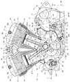
内燃機関20は、車体に対してクランクシャフト21が左右水平方向に指向して横置きに搭載され、シリンダがV字状に前後にバンクした前後V型の2気筒水冷式4ストロークサイクル内燃機関である。
The
前後V型の2気筒内燃機関20は、クランクケース22から斜め上方に前バンクシリンダ23fと後バンクシリンダ23rが延設され、その各上にシリンダヘッド24f,24rが重ねられ、さらにその上にロッカアームホルダー25f,25rを介してシリンダヘッドカバー26f,26rがそれぞれ被せられている。
前バンクシリンダ23fと後バンクシリンダ23rの各シリンダボアの周囲にはウォータジャケット23fw,23rwが形成されている。
The front / rear V-type two-cylinder
Water jackets 23fw and 23rw are formed around the cylinder bores of the
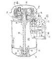
図4を参照して、クランクケース22の後方は、仕切り壁22aで仕切られてミッションケース27が一体に形成されており、クランクケース22とミッションケース27は左右割りに構成され、右側のクランクケース22とミッションケース27の右方はクラッチ・ギヤケース28が付設される。
クラッチ・ギヤケース28は、後方のミッションケース側に右方に開いた開口を有し、同開口をクラッチカバー29が覆う。
Referring to FIG. 4, the rear of the
The clutch /
したがって、クランクケース22と仕切り壁22aによりクランク室22Cが画成され、ミッションケース27と仕切り壁22aによりミッション室27Cが画成され、右側のクランクケース22,ミッションケース27に仕切られクラッチ・ギヤケース28およびクラッチカバー29により覆われてクラッチ室28Cが形成される。
Accordingly, the
なお、クラッチ・ギヤケース28の前部側壁の右方をチェーンカバー30が覆い、左側のクランクケース22の左方をサイドカバー36(図1参照)およびACGカバー31が覆い、左側のミッションケース27の左方をクラッチ駆動機構カバー33が覆う。
The
本前後V型内燃機関20は、前バンクシリンダ23fと後バンクシリンダ23rの各シリンダ中心軸がクランクシャフト21に直交する同一平面上にあって、左右幅方向にオフセットしていない。
In the front and rear V-type
前バンクシリンダ23f内を往復動するピストン40fのピストンピン40fpに小端部を連結した前側コネクティングロッド41と、後バンクシリンダ23r内を往復動するピストン40rのピストンピン40rpに小端部を連結した後側コネクティングロッド45とは、クランクシャフト21の一対のクランクウエブ21w,21w間を連結する共通のクランクピン21pにその各大端部を連結している。
A small end is connected to the front connecting
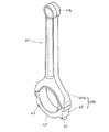
前側コネクティングロッド41は、図9に図示するように、一端に小端部41sを一体に有し、他端の大端部41bがロッド軸に垂直な面で2分割される分割構造をなし、半円弧状の本体側大端部41bhにクランクピン21pを間に挟んで半円弧状のコンロッドキャップ42が合わされて両端をコンロッドボルト43で締結される。
As shown in FIG. 9, the front connecting
他方、後側コネクティングロッド45は、図10ないし図12に示すように、一端に小端部45sを一体に有するのは同じであるが、他端の大端部が2又に分岐して対向する一対の大端部45b,45bからなるとともにロッド軸に垂直な面で2分割される分割構造をなす。
On the other hand, as shown in FIGS. 10 to 12, the rear connecting
すなわち、一対の大端部45b,45bは、2又に分岐した一対の半円弧状のロッド本体側大端半体部45bh,45bhに対して、一対の半円弧状大端半体46bc,46bcがその各中央部を外方(遠心方向)に突出させて、かつ互いの突出部を連結突起部46cで連結して一体化したコンロッドキャップ46を合わせて連結突起部46cの両側方で4隅をコンロッドボルト47で締結して構成される。
That is, the pair of
後側コネクティングロッド45の一対の大端部45b,45bは、前側コネクティングロッド41の大端部41bを間に挟み、大端部41bの両側でクランクピン21pに軸支される(図4参照)。
後側コネクティングロッド45は、一対の大端部45b,45bを構成するコンロッドキャップ46の連結突起部46cが、特に大きく下方に突出している(図2,図8参照)。
The pair of
In the
このように、前側コネクティングロッド41の1個の大端部41bと後側コネクティングロッド45の一対の大端部45b,45bは、大端部41bを中央にして一対の大端部45b,45bが両側に位置し共通の同じクランクピン21pに軸支されるので、カップリング振動が防止される。
Thus, one
なお、後側コネクティングロッド45の一対の大端部45b,45bは、そのコンロッドキャップ46の連結突起部46cが他方の前側コネクティングロッド41のコンロッドキャップ42を跨ぐようにして組み付けられ、両者が干渉するようなことはない。
The pair of
また、前バンクシリンダ23fと後バンクシリンダ23rの各シリンダ中心軸がクランクシャフト21に直交する同一平面上にあって、左右幅方向にオフセットしていないので、内燃機関20の左右幅長を狭くすることができる。
Further, since the cylinder central axes of the
前側コネクティングロッド41と後側コネクティングロッド45に共通のクランクピン21pで連結されて回転駆動されるクランクシャフト21は、左右のクランクケース22にベアリング35,35を介して軸支されている。
The
このクランクシャフト21の右方のクラッチ室28Cに突出した部分にスリーブ50が嵌装され、さらに先端にドライブスプロケット52を備えたキャップ51が被せられてボルト53により一体に固着されている。
ドライブスプロケット52を備えるキャップ51の先端はクラッチ・ギヤケース28の開口から右方に突出している。
A
The tip of the
スリーブ50上にはプライマリギヤ55が軸支され、ダンパー機構56を介してクランクシャフト21の回転が伝達されるようになっている。
クランクシャフト21の左側クランクケース22より左方に突出した部分にはACジェネレータ57が設けられるともに、始動機構のドリブンギヤ58がワンウエイクラッチ59を介して設けられている。
A
An
かかるクランクシャフト21の前後対称位置において、1次振動を打ち消すバランサシャフト60,61が、クランクシャフト21と同一の略水平な面上に平行に配設されて2軸バランサ機構が構成されている。
The
左右のクランクケース22,22に、ベアリング62,62を介して前側バランサシャフト60が回転自在に軸支され(図5参照)、ベアリング63,63を介して後側バランサシャフト61が、回転自在に軸支されている(図4参照)。
前後のバランサシャフト60,61のバランサウエイト60w,61wは、クランクシャフト21の一対のクランクウエブ21w,21w間を旋回する。
The
The
バランサシャフト60,61は、右側クランクケース22に軸支するベアリング62,63を貫通してクラッチ室28Cに突出し、その右突出端にバランサギヤ64,65が嵌着されており、同前後のバランサギヤ64,65は、前記クランクシャフト21に設けられた同径のプライマリギヤ55に噛み合って、クランクシャフト21の回転に連動してバランサシャフト60,61が同じ回転速度で逆回転する。
The
後側バランサシャフト61の後方にメインシャフト66とカウンタシャフト67がミッションケース27に軸支されて配設されている。
A
メインシャフト66の斜め上後方に配置されたカウンタシャフト67は、両端が左右ミッションケース27にベアリングを介して軸支され、メインシャフト66の上方に変速シフト機構75が配置されている。
A
カウンタシャフト67のミッション室27C外に突出した左端にはドライブギヤ14が嵌着されている。
A
メインシャフト66のミッション室27C外に突出した右端には多板クラッチ77が設けられ、多板クラッチ77のメインシャフト66に回転自在に軸支されたクラッチハウジング77hに一体に設けられたメインギヤ78が前記後側バランサシャフト61のバランサギヤ65に噛合している。
なお、メインギヤ78にはオイルポンプ用ギヤ79が一体に形成されている。
A multi-plate clutch 77 is provided at the right end of the
The
このメインシャフト66の中心孔をクラッチ作動軸81が貫通して、その右端は多板クラッチ77のプレッシャプレート77pに連結され、左端は前記クラッチ駆動機構カバー33に設けられたクラッチ駆動機構82に組み込まれている。
The
したがって、内燃機関20の運転でクランクシャフト21が回転すると、ダンパー機構56を介してプライマリギヤ55が回転し、プライマリギヤ55の回転はこれと噛合する前後のバランサギヤ64,65を介して前後のバランサシャフト60,61を回転する。
Therefore, when the
そして、後側のバランサシャフト61のバランサギヤ65の回転は、これと噛合するメインギヤ78を多板クラッチ77のクラッチハウジング77hとともに回転し、多板クラッチ77の係合を介してメインシャフト66を回転する。
The
メインシャフト66の回転は、メインギヤ列とカウンタギヤ列の対応するギヤどうしの噛合のいずれかが変速シフト機構75により選択的に有効となってカウンタシャフト67を回転し、カウンタシャフト67の回転は、一体に嵌合したドライブギヤ14とともに回転し、ドライブギヤ14とドリブンギヤ15とを連結したドライブシャフト16を介して後輪11を回転駆動する。
As for the rotation of the
また、ミッション室27C内において、メインシャフト66の斜め下前方にオイルポンプ85が配置されている(図2参照)。
図6に示すように、オイルポンプ85は、左から順にクランク室スカベンジングポンプ86,フィードポンプ87,クラッチ室スカベンジングポンプ88の3つのポンプからなり、左右方向に指向した共通の回転軸89に各インナロータが嵌着されて設けられている。
In the
As shown in FIG. 6, the
右側のクラッチ室スカベンジングポンプ88のポンプケース88cの右側壁中央に形成された軸受部88cbが突出して右側ミッションケース27の円孔に挿入され、同軸受部88cbを回転軸89が貫通してクラッチ室28Cに突出しており、同回転軸89の突出部にポンプ駆動ギヤ90がボルト91により固着され、同ポンプ駆動ギヤ90は前記オイルポンプ用ギヤ79に噛合している。
A bearing portion 88cb formed at the center of the right side wall of the
したがって、クランクシャフト21の回転が、プライマリギヤ55,バランサギヤ65,メインギヤ78に伝達されて、メインギヤ78と一体のオイルポンプ駆動用ギヤ79を回転すると、これと噛合するポンプ駆動ギヤ90が回転してオイルポンプ85が駆動される。
Therefore, when the rotation of the
なお、ミッション室27C側から右側ミッションケース27の円孔に挿入される軸受部88cbは、該円孔との間隙にオイルシール92が介装されて、ミッション室27Cとクラッチ室28Cとの間をシールしている(図6参照)。
The bearing portion 88cb inserted into the circular hole of the
一方、クランクケース22の後バンクシリンダ23rとの合わせ部の後方にスタータモータ95が駆動軸96を左方へ突出させて配設されており、図2に示すように、同駆動軸96に形成された駆動ギヤ96gに減速ギヤ軸97の大径ギヤ97bが噛合し、同減速ギヤ軸97の小径ギヤ97sに中間軸98の大径中間ギヤ98bが噛合し、同中間軸98の小径中間ギヤ98sが前記クランクシャフト21のドリブンギヤ58に噛合している。
On the other hand, a
したがって、スタータモータ95の回転は、駆動ギヤ96g,大径ギヤ97b,小径ギヤ97s,大径中間ギヤ98b,小径中間ギヤ98s,ドリブンギヤ58に順次伝達され、ワンウエイクラッチ59を介してクランクシャフト21を回転駆動して内燃機関20を始動させることができる。
Accordingly, the rotation of the
次に、吸排気系について説明する。
本内燃機関20は、OHV型の内燃機関であり、シリンダヘッド24f,24rに吸気バルブ101f,101rと排気バルブ102f,102rが設けられているが、動弁カム機構は右側クランクケース22に設けられている。
Next, the intake / exhaust system will be described.
The
吸気バルブ101f,101rと排気バルブ102f,102rは、シリンダヘッド24f,24rの吸気ポート103f,103rと排気ポート104f,104rの燃焼室105f,105rへの開口を開閉可能に設けられている。
The
なお、図4に示すように、後側シリンダヘッド24rの燃焼室105rには、2本の点火プラグ117r,117rが左右に嵌挿されている。
前側シリンダヘッド24fについても、同様に図示しないが2本の点火プラグが燃焼室105fに嵌挿されている。
As shown in FIG. 4, two ignition plugs 117r and 117r are inserted into the left and right in the
Similarly, for the
前側シリンダヘッド24fにおいては、吸気ポート103fが燃焼室105fから後方へ延びてVバンクの間の吸気管110fに連結し(図2参照)、排気ポート104fが燃焼室105fから前方斜め右方へ延びて排気管115に連結する(図1参照)。
他方、後側シリンダヘッド24rにおいては、吸気ポート103rが燃焼室105rから前方へ延びてVバンクの間の吸気管110rに連結し(図2参照)、排気ポート104rが燃焼室105rから後方斜め右方へ延びて排気管116に連結する(図1参照)。
In the
On the other hand, in the
図7に図示するように、前側シリンダヘッド24fから後方へ延設された吸気管110fと後側シリンダヘッド24rから前方へ延設された吸気管110rは、中央で合体して右方に延出する上流側吸気管110cとともに一体形成された吸気管110の分岐管である。
As shown in FIG. 7, an
吸気管110の右方に延びた上流側吸気管110cにはスロットルボディ120が連結され、スロットルボディ120の右側の上流にエアクリーナ130が配置される。
エアクリーナ130は、Vバンクの前後のシリンダ23f,23r、シリンダヘッド24f,24r、シリンダヘッドカバー26f,26rの右側面に沿ってVバンクの間の空間を右側から覆うように配設される。
A
The
吸気管110の前後に分岐した吸気管110f,110rには燃料噴射弁111f,111rが斜め上方に突出して取り付けられており、燃料噴射弁111f,111rの上端が1つの共通のソケット112に嵌合している。
ソケット112には燃料パイプが接続される接続管113が左方に突設されている。
A connecting
一方、前側シリンダヘッド24fから前方斜め右方に延出した排気管115は、図1に示すように、下方へ屈曲して延びた後に、クランクケース22の右側面に沿って後方へ屈曲し、後輪11の右側に前後方向に長尺に配設されたマフラー115mに連結される。
また、後側シリンダヘッド24rから後方に延出した排気管116は、下方へ屈曲して延びた後に、ミッションケース27の右側面に沿って後方へ屈曲し、後輪11の右側に前記マフラー115mの上に平行に配置されたマフラー116mに連結される。
On the other hand, the
Further, the
次に動弁系の機構について説明する。
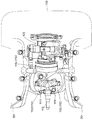
後側シリンダヘッド部24raの上面図である図3を参照して、上記のように吸排気系が構成されるシリンダヘッド24rの上に重ねられるロッカアームホルダー25rは、それぞれ吸気系ロッカアームシャフト150rと排気系ロッカアームシャフト155rをシリンダヘッドカバー26r内において回転自在に保持している。
Next, the mechanism of the valve train will be described.
Referring to FIG. 3 which is a top view of the rear cylinder head portion 24ra, the
図3および図4を参照して、Vバンクの内側となる吸気系ロッカアームシャフト150rには前記吸気バルブ101rを作動するロッカアーム151rと吸気系プッシュロッド153rにより作動されるロッカアーム152rが嵌着されている。
同様に、Vバンクの外側となる排気系ロッカアームシャフト155rには前記排気バルブ102rを作動するロッカアーム156rと排気系プッシュロッド158rにより作動されるロッカアーム157rが嵌着されている。
Referring to FIGS. 3 and 4, a
Similarly, a
吸気系プッシュロッド153rおよび排気系プッシュロッド158rは、上端がシリンダヘッドカバー26r内においてロッカアーム152r、ロッカアーム157rに当接しているが、下端は右側クランクケース22に設けられたクラッチ・ギヤケース28内の動弁カム機構160に連接しており、上下端を除く長尺部分がシリンダ23r、シリンダヘッド24rの右側面に沿って外部にある。
The intake
このように、本動弁機構は、OHV方式が用いられており、動弁カム機構160がクランクケース22側に設けられ、プッシュロッド153r,158rを介してシリンダヘッド24rに設けられた吸気バルブ101rと排気バルブ102rが駆動される構造である。
なお、前側シリンダヘッド24fにおいても同様の構造をしている。
Thus, the main valve mechanism uses the OHV system, and the
The
クラッチ・ギヤケース28内の動弁カム機構160は、前記クランクシャフト21の右端部の上方斜め前と後にカムシャフト161r(前側バンク用カムシャフトは図示しない)がクランクシャフト21と平行に回転自在に軸支されている。
The valve-
図4を参照して、後バンク用カムシャフト161rは、クラッチ・ギヤケース28の側壁を貫通して右方に突出し、その突出端にドリブンスプロケット162rが嵌着されており、前記クラッチ・ギヤケース28の開口から右方に突出したクランクシャフト21に被せられたキャップ51の先端に固着されたドライブスプロケット52と上方斜め前と後のドリブンスプロケット162rにチェーン163が巻き掛けられている。
Referring to FIG. 4, rear bank camshaft 161r penetrates the side wall of clutch /
ドリブンスプロケット162rはドライブスプロケット52の2倍の歯数を有し、したがって、クランクシャフト21の回転は、ドライブスプロケット52からチェーン163を介してドリブンスプロケット162rに伝達され、ドリブンスプロケット162rともに後バンク用カムシャフト161rがクランクシャフト21の半分の回転速度で回転する。
The driven
図4を参照して、後バンク用カムシャフト161rは、それぞれ高速カムと低速カムが隣り合って吸気用で1対、排気用で1対の2対が形成されており、各カムに4個のロッカアーム164rのローラがそれぞれ当接し、この4個のロッカアーム164rは共通のロッカアームシャフト165rに揺動自在に軸支され、弾発付勢手段166rにより高速ロッカアーム164r,164rのローラがカムに押圧されている。
Referring to FIG. 4, the rear bank camshaft 161r has two pairs, one pair for intake and one pair for exhaust, in which a high-speed cam and a low-speed cam are adjacent to each other. The four
ロッカアームシャフト165r内は油圧通路が形成されて、高速カムと低速カムに対応する高速ロッカアーム164rと低速ロッカアーム164r間に形成された係脱機構に油圧を作用することができ、低速ロッカアーム164r,164rの揺動端が前記吸気系プッシュロッド153rと排気系プッシュロッド158rの下端部を受けとめている。
A hydraulic passage is formed in the
したがって、係脱機構に油圧が作用していないときは、高速ロッカアーム164rと低速ロッカアーム164rが離脱して互いに独立に揺動し、低速ロッカアーム164rの先端に受けとめられた吸気系プッシュロッド153rと排気系プッシュロッド158rは低速カムに従って昇降し吸気バルブ101rと排気バルブ102rが低速バルブタイミングで作動する。
Therefore, when no hydraulic pressure is applied to the engagement / disengagement mechanism, the high-
これに対して、係脱機構に油圧が作用するときは、高速ロッカアーム164rと低速ロッカアーム164rが係合して一体に揺動し、低速ロッカアーム164rの先端に受けとめられた吸気系プッシュロッド153rと排気系プッシュロッド158rは高速カムに従って昇降し吸気バルブ101rと排気バルブ102rが高速バルブタイミングで作動する。
On the other hand, when hydraulic pressure acts on the engagement / disengagement mechanism, the high-
前バンク用カムシャフトも、後バンク用カムシャフト161rと前後対称的に同様の部材である4個のロッカアーム、ロッカアームシャフト、弾発付勢手段が吸気系プッシュロッドと排気系プッシュロッドとともに、同様の構造を構成し、吸気バルブ101fと排気バルブ102fは、係脱機構に油圧が作用していないときは低速バルブタイミングで作動し、係脱機構に油圧が作用するときは高速バルブタイミングで作動する。
The front bank camshaft is also similar to the rear bank camshaft 161r in the same direction as the four rocker arms, rocker arm shafts, and the elastic urging means together with the intake system push rod and the exhaust system push rod. In the structure, the
この係脱機構への油圧を制御する油圧制御弁168が、左側クランクケース22の側壁の前側バランサシャフト60の左方延長部分に取り付けられている(図5参照)。
左側クランクケース22の同部分に取り付けられる油圧制御弁168は、サイドカバー36により覆われる(図1参照)。
A
The
次に潤滑系について説明する。
前記クランクシャフト21の左右のクランクウエブ21w,21wとその間の後側コネクティングロッド45の大端部45b,45bの連結突起部46cが旋回するクランク室22Cには、図8に示すように、そのクランクケース22の底部に連結突起部46cの旋回する最大径の軌跡に沿った円弧状のオイル溜り170が形成されており、オイル溜り170に隣接して後方にオイル排出口171が開口してオイル溜り170の後隣りの小油室172に連通している。
Next, the lubrication system will be described.
As shown in FIG. 8, the
オイル排出口171は、オイル溜り170の底壁の一部が若干斜め上方に向かって小油室172内に突出して排出案内リブ171aを形成しており、小油室172の底面に沿った後部に導出口A1aが開口している。
なお、小油室172内に突出した排出案内リブ171aにより小油室172からオイル溜り170にオイルが戻るのが防止されている。
In the
The oil is prevented from returning from the
導出口A1aはミッション室27C内に配管されるオイル管A2に連通する連通油路A1の開口であり、オイル管A2は、オイルポンプ85のうちクランク室スカベンジングポンプ86にオイルが吸入される吸入油路A3と連通している。
The outlet A1a is an opening of the communication oil passage A1 communicating with the oil pipe A2 piped in the
図8に示すように、後側コネクティングロッド45の大端部45b,45bの連結突起部46cの動きをみると、後方に傾いた後バンクシリンダ23rのピストン40rの下死点付近で連結突起部46cはオイル溜り170に溜まったオイルに前方から浸かり、次いで後方のオイル排出口171に向けて旋回移動することで、図8において2点鎖線で示す連結突起部46c’、46c”を参照して、連結突起部46cは、その後面46cbの平坦面がオイル溜り170に溜まったオイルを押してオイル排出口171に掻き出す効果的な動きをし(図8において連結突起部46c’の時点のオイルの表面の状態を2点鎖線で示している)、オイル溜り170からオイルを小油室172に効率良く排出することができる。
As shown in FIG. 8, when the movement of the connecting
なお、オイル溜り170のオイルを掻き出す連結突起部46cは、前側コネクティングロッド41に設けるよりも、後側コネクティングロッド45の大端部45b,45bに設ける方が、図8に示すように、オイルをオイル排出口171に掻き出すより効果的な動きをし、オイルをより一層効率良く排出することができる。
また、連結突起部46cの後面46cbは、凹面に形成して、1回のオイルの掻き出し量を多くするようにしてもよい。
It should be noted that the connecting
Further, the rear surface 46cb of the connecting
なお、後側コネクティングロッド45の大端部45b,45bが、ロッド軸に垂直な面で2分割される分割構造をなすので、コンロッドキャップ46の一対の半円弧状大端半体46bc,46bcを一体に形成することができ、加工および組付けを容易にすることができる。
Since the
また、ロッド本体側大端半体部45bh,45bhに対してコンロッドキャップ46の一対の半円弧状大端半体46bc,46bcを合わせて連結突起部46cの両側方で4隅をコンロッドボルト47で締結して大端部45b,45bを構成するので、連結突起部46cの形状がコンロッドボルト47によって制約を受けることがなく、自由度が高く、オイルを効率良く掻き出すことができる形状を容易に形成することができる。
Further, the pair of semicircular arc large end halves 46bc and 46bc of the connecting
このようにクランク室22Cのオイル溜り170に溜まったオイルは、後側コネクティングロッド45の連結突起部46cの掻き出しによりオイル排出口171より小油室172に排出され、小油室172に排出されたオイルは、導出口A1aより連通油路A1に導かれオイル管A2,吸入油路A3を介してオイルポンプ85のうち左側のクランク室スカベンジングポンプ86に吸入される(図2参照)。
Thus, the oil accumulated in the
クランク室スカベンジングポンプ86から上方に吐出管175が延出しており、クランク室スカベンジングポンプ86により吐出されたオイルを吐出管175よりミッション室27C内の互いに噛合するメインギヤ列72とカウンタギヤ列73に飛沫噴出して供給する。
A
一方、図2および図5を参照して、クラッチ・ギヤケース28の底壁にはプライマリギヤ55の下方から後方へ向かい後側のバランサギヤ65の後方まで延びるオイル通路B1が形成されており、同オイル通路B1は、プライマリギヤ55の下方辺りに連通口B1aを開口してクラッチ室28Cと連通しており、オイル通路B1の後端はクラッチ室28C内に膨出して架設したストレーナ(図示せず)に通じ、同ストレーナを介して吸入油路がオイルポンプ85のうち右側のクラッチ室スカベンジングポンプ88に連結されている(図6参照)。
2 and 5, an oil passage B1 extending from the lower side of the
したがって、クラッチ室スカベンジングポンプ88の稼動でクラッチ室28C内のオイルがオイル通路B1を通り、ストレーナを経て吸入される。
Therefore, when the clutch chamber scavenging pump 88 is operated, the oil in the
図2および図6を参照して、ミッション室27Cの底に溜まるオイルは、ストレーナ185を介して吸入管C1からオイルポンプ85のうち中央のフィードポンプ87により吸入される。
そして、フィードポンプ87からはオイルが吐出油路C2に吐出され、吐出油路C2はミッションケース27の後部下方に取り付けられたオイルフィルタ186の流入口に結合され、オイルフィルタ186からはメインギャラリMに流出される。
Referring to FIGS. 2 and 6, the oil accumulated at the bottom of
Then, oil is discharged from the
メインギャラリMは、オイルフィルタ186から前方へ延出するメインオイル通路M1がクランク室22Cの後方に隣接する小油室172内に膨出して左右方向に指向するメインオイル通路M2に連通し、メインオイル通路M2の左右端で屈曲して左右側クランクケース22の側壁を前後方向にメインオイル通路M3,M3が延出形成されており、前方に延びたメインオイル通路M3,M3の途中から上方へ枝分かれしたオイル通路D1,D1がクランクシャフト21の左右ジャーナル部にオイルを供給する(図2,図5参照)。
The main gallery M communicates with the main oil passage M2 extending forward from the
図2を参照して、左側クランクケース22を前方に延びたメインオイル通路M3は、オイル通路D1の分岐を通り越した前端で上方に延びた後に前方に屈曲して前記油圧制御弁168に至るオイル通路E1に連通している。
Referring to FIG. 2, the main oil passage M3 extending forward through the
油圧制御弁168からは、左側クランクケース22を右方の前側バランサシャフト60に向けてオイル通路F1が形成される(図5参照)とともに、上方に向けてオイル通路E2が形成されている(図2参照)。
油圧制御弁168は、オイル通路E1より流入する圧油を上方に向かうオイル通路E2に送るか、前側バランサシャフト60に向かうオイル通路F1に流出するかを切り換えることができる。
From the
The
上方に延びたオイル通路E2は、上端で右方へ屈曲して右側クランクケース22にまで延びたオイル通路E3になり、図2を参照してオイル通路E3は右側クランクケース22の側壁で後方斜め上に屈曲した後に後方へ水平に延びるオイル通路E4となり、オイル通路E4は斜め上方に屈曲して動弁カム機構160の後側ロッカアームシャフト165r内の油圧通路に連通するオイル通路E5となり、オイル通路E5の途中から斜め前方に分岐したオイル通路E6が前側ロッカアームシャフト165f内の油圧通路に連通している。
The oil passage E2 extending upward becomes an oil passage E3 that is bent rightward at the upper end and extends to the
前後のロッカアームシャフト165f,165r内の油圧通路は、ロッカアーム164f,164rの係脱機構に連通し油圧を作用させることができるようになっている。
したがって、油圧制御弁168がオイル通路E2に圧油を送ると、係脱機構に油圧を作用させることができ、吸気バルブ101f,101rと排気バルブ102f,102rが高速バルブタイミングで作動する
The hydraulic passages in the front and rear
Therefore, when the
他方、油圧制御弁168が弁を切り換えてオイルをオイル通路F1に流出させると、係脱機構に油圧が作用せず、吸気バルブ101f,101rと排気バルブ102f,102rが低速バルブタイミングで作動する。
このとき、オイル通路F1に流出したオイルは、図5に示すように、前側バランサシャフト60の左側ベアリング62に供給されるとともに、前側バランサシャフト60の中心孔60aを通って右端開口からクランク室22C内に排出される。
On the other hand, when the
At this time, as shown in FIG. 5, the oil that has flowed into the oil passage F1 is supplied to the left bearing 62 of the
このように、油圧制御弁168は、左側クランクケース22の側面でクランクシャフト21と同じ高さの前側バランサシャフト60の左方に配置されるので、シリンダ23f,23rから離れていてシリンダ23f,23rの熱の影響を直接受けることがないため、油圧制御弁168を正確に作動してバルブタイミングを精度良く変更することができる。
In this manner, the
また、前側シリンダヘッド24fの前方斜め右に向いた排気ポート104fに連結された排気管115が下方へ屈曲して延びた後に、クランクケース22の右側面に沿って後方へ延びているのに対して、油圧制御弁168はクランクケース22の左側面に設けられるので、排気管115の熱の影響も受け難い。
In contrast, the
油圧制御弁168に供給されるオイルを利用して前側バランサシャフト60を潤滑することができ、また前側バランサシャフト60の中心孔60aをオイル通路として油圧制御弁168から流出するオイルをクランク室22C内に排出することができるので、バランサシャフトを潤滑するためのオイル通路やオイル回収通路を別途特別に設ける必要がなく、潤滑油経路が簡素化される。
The oil supplied to the
また、OHV方式の動弁機構が採用されて動弁カム機構160がクランクケース22に設けられているので、同じくクランクケース22に設けられる油圧制御弁168から動弁カム機構160の油圧を作用させる係脱機構までのオイル通路E2,E3,E4,E5を短くすることができ、益々潤滑油経路が簡素化される。
Further, since the OHV type valve mechanism is employed and the
なお、油圧制御弁168は、左側クランクケース22の側壁に取り付けられるので、サイドカバー36により覆われるので、外に露出することがなく、内燃機関の外観を良好に保つことができる。
Since the
以上の実施の形態では、後バンクシリンダ23r内を往復動するピストン40rのピストンピン40rpに小端部を連結した1本の後側コネクティングロッド45が、他端の大端部を2又に分岐していたが、後側コネクティングロッドを2本で構成してもよい。
In the above embodiment, one
すなわち、図13に図示するように、対称形状をなす一対の後側コネクティングロッド215,216は、その一対の小端部215s,216sが共通のピストンピン40rpに軸支され、他方の大端部215b,216bが、ロッド軸に垂直な面で分割され、ロッド本体側大端半体部215bh,216bhに対して、一対の半円弧状大端半体217bc,217bcがその各中央部を外方(遠心方向)に突出させて、かつ互いの突出部を連結突起部217cで連結して一体化したコンロッドキャップ217を合わせてコンロッドボルト218で締結して構成される。
That is, as shown in FIG. 13, a pair of rear connecting
なお、コンロッドキャップ217自体は、前記実施の形態のコンロッドキャップ46と略同じ形状で、同じものを利用することができる。
前側コネクティングロッド211は、前記実施の形態の前側コネクティングロッド41と同じもので、大端部のコンロッドキャップ212がコンロッドボルトでロッド本体側の大端半体部に締結される。
The connecting
The front connecting rod 211 is the same as the
本後側コネクティングロッド215,216は、その連結突起部217cとともに、図8に示すような前記後側コネクティングロッド45と同じ動きをするので、連結突起部217cの後面がオイル溜り170に溜まったオイルを押してオイル排出口171に掻き出す効果的な動きをし、オイル溜り170からオイルを小油室172に効率良く排出することができ、運転状態の如何にかかわらず潤滑オイルの循環を円滑に行うことができる。
The
20…内燃機関、21…クランクシャフト、22…クランクケース、23f…前バンクシリンダ、23r…後バンクシリンダ、60,61…バランサシャフト、
85…オイルポンプ、86…クランク室スカベンジングポンプ、87…フィードポンプ、88…クラッチ室スカベンジングポンプ、
101f,101r…吸気バルブ、102f,102r…排気バルブ、103f,103r…吸気ポート、104f,104r…排気ポート、105f,105r…燃焼室、110…吸気管、115,116…排気管、 160…動弁カム機構、161f,161r…カムシャフト、168…油圧制御弁、
186…オイルフィルタ、M…メインギャラリ、M1,M2,M3…メインオイル通路、D1…オイル通路、E1,E2,E3,E4,E5…オイル通路。
20 ... Internal combustion engine, 21 ... Crankshaft, 22 ... Crankcase, 23f ... Front bank cylinder, 23r ... Rear bank cylinder, 60, 61 ... Balancer shaft,
85 ... Oil pump, 86 ... Crank chamber scavenging pump, 87 ... Feed pump, 88 ... Clutch chamber scavenging pump,
101f, 101r ... intake valve, 102f, 102r ... exhaust valve, 103f, 103r ... intake port, 104f, 104r ... exhaust port, 105f, 105r ... combustion chamber, 110 ... intake pipe, 115, 116 ... exhaust pipe, 160 ... motion Valve cam mechanism, 161f, 161r ... camshaft, 168 ... hydraulic control valve,
186 ... Oil filter, M ... Main gallery, M1, M2, M3 ... Main oil passage, D1 ... Oil passage, E1, E2, E3, E4, E5 ... Oil passage.
Claims (4)
前記内燃機関は、クランクシャフトに連動する回転軸をクランクケース内に備え、
前記動弁系油圧制御弁が、シリンダ下方においてクランクシャフトを支持しかつ覆うクランクケースの側面の前記回転軸と同軸線上に配置されたことを特徴とする内燃機関の動弁系油圧制御弁配置構造。 An internal combustion engine comprising: a valve operating characteristic changing mechanism that changes an operating characteristic of at least one of an intake valve and an exhaust valve; and a valve operating hydraulic control valve that controls the hydraulic pressure of hydraulic oil supplied to the valve operating characteristic changing mechanism In
The internal combustion engine is provided with a rotating shaft in conjunction with the crankshaft in the crankcase,
A valve operating system hydraulic control valve arrangement structure for an internal combustion engine, wherein the valve operating system hydraulic control valve is arranged coaxially with the rotating shaft on a side surface of a crankcase that supports and covers a crankshaft below the cylinder .
Priority Applications (2)
| Application Number | Priority Date | Filing Date | Title |
|---|---|---|---|
| JP2006120503A JP4868927B2 (en) | 2005-08-31 | 2006-04-25 | Valve system hydraulic control valve arrangement structure of internal combustion engine |
| US11/511,329 US7438031B2 (en) | 2005-08-31 | 2006-08-29 | Layout structure of hydraulic control valve for valve train in internal combustion engine |
Applications Claiming Priority (3)
| Application Number | Priority Date | Filing Date | Title |
|---|---|---|---|
| JP2005251805 | 2005-08-31 | ||
| JP2005251805 | 2005-08-31 | ||
| JP2006120503A JP4868927B2 (en) | 2005-08-31 | 2006-04-25 | Valve system hydraulic control valve arrangement structure of internal combustion engine |
Publications (3)
| Publication Number | Publication Date |
|---|---|
| JP2007092743A JP2007092743A (en) | 2007-04-12 |
| JP2007092743A5 JP2007092743A5 (en) | 2009-04-09 |
| JP4868927B2 true JP4868927B2 (en) | 2012-02-01 |
Family
ID=37802299
Family Applications (1)
| Application Number | Title | Priority Date | Filing Date |
|---|---|---|---|
| JP2006120503A Expired - Fee Related JP4868927B2 (en) | 2005-08-31 | 2006-04-25 | Valve system hydraulic control valve arrangement structure of internal combustion engine |
Country Status (2)
| Country | Link |
|---|---|
| US (1) | US7438031B2 (en) |
| JP (1) | JP4868927B2 (en) |
Families Citing this family (8)
| Publication number | Priority date | Publication date | Assignee | Title |
|---|---|---|---|---|
| JP5013815B2 (en) * | 2006-10-31 | 2012-08-29 | 本田技研工業株式会社 | Power unit for vehicle |
| EP2194243B1 (en) * | 2007-09-29 | 2012-03-14 | Honda Motor Co., Ltd. | Power unit for small-sized vehicle |
| JP5123642B2 (en) * | 2007-10-31 | 2013-01-23 | 本田技研工業株式会社 | Small saddle-ride type vehicle |
| HRP20080020A2 (en) * | 2008-01-15 | 2009-07-31 | Marić Franjo | Cylindrical engine with internal combustion |
| US8191515B2 (en) * | 2008-06-24 | 2012-06-05 | Honda Motor Co., Ltd. | V-type internal combustion engine including throttle valve device, and vehicle incorporating same |
| US8857417B2 (en) * | 2009-12-30 | 2014-10-14 | Kawasaki Jukogyo Kabushiki Kaisha | Engine for vehicle |
| US11156154B2 (en) * | 2015-12-09 | 2021-10-26 | Honda Motor Co., Ltd. | Internal combustion engine |
| JP6972812B2 (en) * | 2017-09-13 | 2021-11-24 | スズキ株式会社 | Oil control valve mounting structure and motorcycle |
Family Cites Families (7)
| Publication number | Priority date | Publication date | Assignee | Title |
|---|---|---|---|---|
| US2786457A (en) * | 1954-04-14 | 1957-03-26 | Fairchild Engine & Airplane | Engine exhaust disposal system |
| JP2741492B2 (en) * | 1994-11-30 | 1998-04-15 | 本田技研工業株式会社 | Engine oil passage structure |
| JP4020346B2 (en) * | 1998-10-12 | 2007-12-12 | ヤマハ発動機株式会社 | Engine decompression mechanism |
| JP3447601B2 (en) * | 1999-02-05 | 2003-09-16 | 本田技研工業株式会社 | Valve operating control device for internal combustion engine |
| JP2000265849A (en) * | 1999-03-15 | 2000-09-26 | Honda Motor Co Ltd | Generator device for vehicle |
| JP2002180812A (en) | 2000-12-13 | 2002-06-26 | Honda Motor Co Ltd | V-type engine |
| JP3922913B2 (en) * | 2001-11-20 | 2007-05-30 | ヤマハマリン株式会社 | V type 4-cycle engine for outboard motor |
-
2006
- 2006-04-25 JP JP2006120503A patent/JP4868927B2/en not_active Expired - Fee Related
- 2006-08-29 US US11/511,329 patent/US7438031B2/en not_active Expired - Fee Related
Also Published As
| Publication number | Publication date |
|---|---|
| US20070044744A1 (en) | 2007-03-01 |
| US7438031B2 (en) | 2008-10-21 |
| JP2007092743A (en) | 2007-04-12 |
Similar Documents
| Publication | Publication Date | Title |
|---|---|---|
| JP4767080B2 (en) | Intake structure of V-type internal combustion engine | |
| JP4868927B2 (en) | Valve system hydraulic control valve arrangement structure of internal combustion engine | |
| JP4691465B2 (en) | Breather structure of internal combustion engine | |
| TWI222944B (en) | Engine for motorcycles | |
| US7216615B2 (en) | Engine device for motorcycles | |
| JP4698544B2 (en) | Internal combustion engine | |
| JP4727600B2 (en) | Overhead internal combustion engine | |
| JP5048618B2 (en) | 4-cycle air-oil cooled engine | |
| JP4636507B2 (en) | Crank chamber lubrication structure for V-type internal combustion engine | |
| JP2008308989A (en) | Engine and vehicle equipped with the same | |
| JP2007024007A (en) | Lubricating device of internal combustion engine | |
| JP4636508B2 (en) | Reed valve arrangement structure of internal combustion engine | |
| JP4321100B2 (en) | Secondary balancer for outboard motor vertical engine | |
| JP2007106348A (en) | Scooter type vehicle | |
| JP2002276317A (en) | Multiple cylinder 4-cycle internal combustion engine | |
| JP4244307B2 (en) | Water-cooled engine | |
| JP2014125931A (en) | Dry sump type lubrication structure of internal combustion engine | |
| JP2013007275A (en) | Gas-liquid separation structure for engine | |
| JP2012255365A (en) | Oil lubricating structure for dry sump type engine | |
| JP4270954B2 (en) | Motorcycle | |
| JP4105057B2 (en) | Internal combustion engine with starter motor | |
| JP4892531B2 (en) | Oil passage structure for cooling in vehicle engine | |
| JP3896805B2 (en) | 4-cycle engine for outboard motor | |
| JP2008240705A (en) | Vehicular internal combustion engine | |
| JP2007100541A (en) | Lubricating oil passage structure of internal combustion engine |
Legal Events
| Date | Code | Title | Description |
|---|---|---|---|
| A521 | Written amendment |
Free format text: JAPANESE INTERMEDIATE CODE: A523 Effective date: 20090225 |
|
| A621 | Written request for application examination |
Free format text: JAPANESE INTERMEDIATE CODE: A621 Effective date: 20090225 |
|
| RD04 | Notification of resignation of power of attorney |
Free format text: JAPANESE INTERMEDIATE CODE: A7424 Effective date: 20090501 |
|
| A977 | Report on retrieval |
Free format text: JAPANESE INTERMEDIATE CODE: A971007 Effective date: 20110117 |
|
| A131 | Notification of reasons for refusal |
Free format text: JAPANESE INTERMEDIATE CODE: A131 Effective date: 20110405 |
|
| A521 | Written amendment |
Free format text: JAPANESE INTERMEDIATE CODE: A523 Effective date: 20110602 |
|
| TRDD | Decision of grant or rejection written | ||
| A01 | Written decision to grant a patent or to grant a registration (utility model) |
Free format text: JAPANESE INTERMEDIATE CODE: A01 Effective date: 20111115 |
|
| A01 | Written decision to grant a patent or to grant a registration (utility model) |
Free format text: JAPANESE INTERMEDIATE CODE: A01 |
|
| A61 | First payment of annual fees (during grant procedure) |
Free format text: JAPANESE INTERMEDIATE CODE: A61 Effective date: 20111115 |
|
| R150 | Certificate of patent or registration of utility model |
Ref document number: 4868927 Country of ref document: JP Free format text: JAPANESE INTERMEDIATE CODE: R150 Free format text: JAPANESE INTERMEDIATE CODE: R150 |
|
| FPAY | Renewal fee payment (event date is renewal date of database) |
Free format text: PAYMENT UNTIL: 20141125 Year of fee payment: 3 |
|
| LAPS | Cancellation because of no payment of annual fees |