JP4865965B2 - Liquid treatment apparatus and method using ultraviolet rays - Google Patents
Liquid treatment apparatus and method using ultraviolet rays Download PDFInfo
- Publication number
- JP4865965B2 JP4865965B2 JP2001244654A JP2001244654A JP4865965B2 JP 4865965 B2 JP4865965 B2 JP 4865965B2 JP 2001244654 A JP2001244654 A JP 2001244654A JP 2001244654 A JP2001244654 A JP 2001244654A JP 4865965 B2 JP4865965 B2 JP 4865965B2
- Authority
- JP
- Japan
- Prior art keywords
- discharge lamp
- ultraviolet
- arc tube
- wavelength
- liquid
- Prior art date
- Legal status (The legal status is an assumption and is not a legal conclusion. Google has not performed a legal analysis and makes no representation as to the accuracy of the status listed.)
- Expired - Lifetime
Links
Images


Description
【0001】
【発明の属する技術分野】
本発明は、220nm以下の短波長域紫外線と254nmの紫外線を共存放射する放電灯を使用して、液体中の有機物の分解などの処理を行う液体処理装置及び方法に関する。
【0002】
【従来技術】
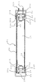
220nm以下の短波長域の紫外線は強いエネルギーを有することから、有害物や有機物の分解など多岐にわたって利用されている。図10は、従来知られた閉鎖型の液体処理用紫外線照射装置の一例を示す。放電灯30を外管(保護管)20内に収納したものが、ステンレス製のシリンダー1内に収容され、被処理液体が該シリンダー1内に導入されて放電灯30から発光した紫外線が照射される。放電灯30としては、例えば185nmの短波長域紫外線と254nmの波長域の紫外線との両方を放射する低圧水銀蒸気放電灯が使用される。放電灯30の発光管バルブ10は紫外線透過性に優れた石英ガラスからできている。放電灯30は紫外線透過性の外管(保護管)20の内部に収納され、該放電灯30が被処理液体から液密に隔離される。かかる外管20も紫外線透過性に優れた石英ガラスでできている。シリンダー1の両端はフランジ1a,1bで閉じられており、入水口1cから取り入れられた被処理液体が、シリンダー1内を通過する過程で紫外線が照射され、出水口1dから排出される。被処理液体は、入水口1cから出水口1dに向かってシリンダー1内を流れることになるが、被処理液体がショートパスしないように、途中に複数枚(図では5枚)の還流板1e〜1iを配置した構造になっている。なお、便宜上、図10には放電灯30を1灯だけ搭載した装置を図示したが、実用的には多灯式の大容量装置が使用される場合が多い。放電灯30から発せられた紫外線は、外管20を透過し、被処理液体に照射される。照射された紫外線は、例えば水中に存在する有機物を次式のように無害なCO、CO2、H2Oに分解する作用を果たすことになる。
【0003】
H2O + hν(185nm)→ H + OHラジカル
Cn Hm Ok + OHラジカル → CO、CO2、H2O
(n,m,k, は 1,2,3,……)
【0004】
この有機物の分解は185nmの短波長域の紫外線の作用によるものであるが、短波長域の紫外線の過多は、過酸化水素(H2O2)を初めとして、意図しない種々の過酸化物が中間体として生成させる。こうした過酸化物を除去するために、紫外線照射処理の後段において紫外線照射処理済みの被処理液体をイオン交換樹脂に通す工程が設けられている。従って、これらの過酸化物は被処理液体がイオン交換樹脂を通った時に除去されるが、過剰の過酸化物はイオン交換樹脂の寿命劣化を招くことになる。
【0005】
【発明の解決しようとする課題】
本発明は上述の点に鑑みてなされたもので、過酸化物が生成されることをできるだけ抑制できるようにした液体処理が行える紫外線による液体処理装置及び方法を提供しようとするものである。またこれに伴い、紫外線照射処理の後段において使用されるイオン交換樹脂の寿命も延ばすことができるようにし、長寿命、省エネルギーかつ省メンテナンスの液体処理装置及び方法を提供しようとするものである。
【0006】
【課題を解決するための手段】
本発明に係る紫外線による液体処理装置は、220nm以下の波長の紫外線と254nmの波長の紫外線とを共存発光する放電灯から放射される紫外線を処理対象液体に照射し、前記220nm以下の波長の紫外線により該処理対象液体の有機物分解処理を行う液体処理装置であって、前記220nm以下の波長の紫外線は処理対象液体中の水分子を解離してOHラジカルを生成し、該生成されたOHラジカルによって有機物を分解することに寄与し、前記254nmの波長の紫外線は、前記220nm以下の波長の紫外線による有機物分解過程で前記処理対象液体中に発生した中間体である過酸化物を分解するのに寄与し、前記放電灯は、内表面に金属酸化物の薄膜が形成された石英ガラス製発光管を備えており、該金属酸化物の薄膜によって当該放電灯の点灯中に生成される酸化水銀の当該発光管の内表面への吸着を防止し、もって、前記254nmの波長の紫外線の照度低下を防ぐようにしたものであり、前記放電灯の発光管の管体が、内径8ミリメートル乃至23ミリメートルの合成石英ガラスからなり、この発光管の管体の両端にLセンチメートルの間隔で一対のフィラメントを備え、該放電灯を0.4アンペア〜1.4アンペアのランプ電流で動作させ、点灯時のランプ電圧Vボルトと、ランプ電流Iアンペア、フィラメント間距離Lセンチメートル、放電路の内径Dミリメートルについて、次なる関係式を有することを特徴とする。
(V−Vf)/L=X/(√D・√I) かつ、
2.6 ≦ X ≦ 4.2。
ただし、Vfは点灯電源に依存する定数要因で、1kHZ以上の高周波電源で点灯した場合はVf=10とし、1kHZ未満の電源で点灯した場合はVf=50とする。
本発明によると、220nm以下の波長の紫外線は処理対象液体中の水分子を解離してOHラジカルを生成し、該生成されたOHラジカルによって有機物を分解することに寄与し、その一方で、254nmの波長の紫外線は該有機物分解過程で過剰なOHラジカルによって生成される過酸化物を分解するのに寄与するので、254nmの波長の紫外線も有用であるところ、放電灯の発光管の内表面に金属酸化物の薄膜を形成することで、放電灯の点灯中に生成される酸化水銀が発光管の内表面に吸着するのを防止でき、有用な254nmの波長の紫外線の照度低下を抑制することができる。
【0007】
220nm以下の紫外線と254nmの紫外線を共存発光する放電灯にあっては、220nm以下の波長域の紫外線が有機物の分解の光化学処理に関与する。一方、254nmの波長域の紫外線は、中間体である過酸化物の分解の重要な役割を担っており、紫外線照射処理の後段において使用されるイオン交換樹脂の負担を軽減している。ところで、放電灯の紫外線照度は使用時間経過に伴い低下するものだが、220nm以下の短波長域の紫外線と254nmの波長域の紫外線とでは、紫外線照度低下の原因を異にする。220nm以下の短波長域の紫外線照度低下は、放電灯の管体を成す石英ガラスが、紫外線を浴びて変質し紫外線透過率が低下することが原因である。他方、254nmの波長域の紫外線の照度低下は、放電灯の点灯中に管内に生じた酸素が水銀と反応し生成された酸化水銀が、石英ガラス内表面に吸着して、石英ガラスの紫外線透過率が低下することに因る。そのため、220nm以下の短波長域の紫外線と254nmの波長域の紫外線とでは、図9に例示するように、それぞれの紫外線照度維持特性が異なり、254nmの紫外線の方が照度低下の進行が早いので、図9における254nmの維持率が220nm以下(例えば、185nm)の紫外線照度維持率を下回るC点以降は、過酸化物の増大を招くと考えられる。これに対して、本発明によると、放電灯の発光管内表面に金属酸化物の薄膜を形成することで、放電灯の点灯中に生成される酸化水銀が発光管内表面に吸着するのを防止でき、254nmの紫外線の照度低下を抑制することができる。
【0008】
また、本発明は、上記の液体処理装置において、前記放電灯の発光管の管体が、天然の水晶もしくは珪砂を出発原料とし、ナトリウム、カリウム、チタニウムおよび鉄の4種からなる元素の総含有量が2.5ppm(ただし質量割合)以下であって、10ppm(ただし質量割合)以上のOH基を含む石英ガラスからなることを特徴とする。
【0009】
天然の水晶もしくは珪砂を出発原料とする石英ガラスにあっては、各種の物質が不純物として含まれている。これらの不純物の中でも、ナトリウム(Na)、カリウム(K)、チタニウム(Ti)および鉄(Fe)の4種の元素が多く存在すると、石英ガラスの透過率低下をきたす原因となる。その一方で、OH基の存在が石英ガラスの変質を緩和させ得る。すなわち、石英ガラスの主成分である二酸化珪素(SiO2)の「Si−O」の結合が紫外線エネルギーによって分解されて透過率低下の原因となるフリーのSiが生成されるのを、OH基がフリーのSiと再結合して「Si−OH」になることで抑制することができる。発明者による実験・研究の結果、これらの4種の元素の総含有量が2.5ppm以下であって、10ppm以上のOH基を含むようにすると、短波長域紫外線による石英ガラスの経時劣化をかなり改善できることが判明した。よって、石英ガラスの材質をそのように選定若しくは設定することにより、220nm以下の短波長域紫外線の照度維持率を高めることができ、このように高性能な放電灯の発光管内表面に金属酸化物の薄膜を形成することで、254nmの紫外線の照度低下を抑制する効果が一層発揮される。
【0010】
また、本発明は、上記の液体処理装置において、前記放電灯の発光管の管体が、内径8ミリメートル乃至23ミリメートルの合成石英ガラスからなり、この発光管の管体の両端にLセンチメートルの間隔で一対のフィラメントを備え、該放電灯を0.4アンペア〜1.4アンペアのランプ電流で動作させ、点灯時のランプ電圧Vボルトと、ランプ電流Iアンペア、フィラメント間距離Lセンチメートル、放電路の内径Dミリメートルについて、次なる関係式を有することを特徴とする。
(V−Vf)/L=X/(√D・√I) かつ、
2.6 ≦ X ≦ 4.2。
ただし、Vfは点灯電源に依存する定数要因で、1kHZ以上の高周波電源で点灯した場合はVf=10とし、1kHZ未満の電源で点灯した場合はVf=50とする。詳細は後述するが、上記関係式のように条件設定することによって、220nm以下の短波長域の紫外線を効率よく放射させることができ、かかる高性能な放電灯の発光管内表面に金属酸化物の薄膜を形成することで、254nmの紫外線の照度低下を抑制する効果が一層発揮される。
【0011】
本発明の好ましい実施態様は、前記放電灯の発光管内表面に形成する金属酸化物の薄膜が、アルミニウム、ケイ素、カルシウム、マグネシウム、イットリウム、ジルコニウム及びハフニウムの中から選ばれた金属の少なくとも一種類以上の酸化物を主成分とすることである。これらの金属酸化物は、耐熱性に優れ科学的に安定であるため、酸化水銀の発光管内表面への吸着防止に有効に作用する。
【0012】
更に本発明に係る紫外線による液体処理方法は、上記のような発光管内表面に金属酸化物の薄膜を形成してなる放電灯を使用して、処理対象液体に対して紫外線を照射し、該液体の有機物分解処理等を行うことを特徴としている。
【0013】
【発明の実施の形態】
以下、添付図面を参照して本発明の実施の形態について説明する。
図1に本発明に係る液体処理装置及び方法で使用する放電灯の一実施例を示す。まず、この放電灯31の基本的構造について説明すると、放電灯31は、220nm以下例えば185nmの短波長域紫外線と254nmの紫外線を共存発光するように構成されており、発光管バルブ11と、該発光管バルブ11内でその両端に配置された一対のフィラメント21a、21bと、該発光管バルブ11の両端に設けられたシール部2a、2bおよび口金部3a、3bとを含む。発光管バルブ11は、一例として内径13mm、肉厚1mmの合成石英ガラスからなり、ガラス内表面には金属酸化物の薄膜44が形成されている。薄膜44は、例えば酸化アルミニウムのような耐熱性に優れ化学的に安定した物質からなる。フィラメント21a、21bは、両フィラメント間が153cmの間隔で配置されている。
このフィラメント21a、21bは、例えば酸化バリウム系のエミッターを塗布してなり、シール部2a、2bから出ているインナーリード22a〜22dによってそれぞれ保持されている。口金部3a、3bはセラミック製であり、一方の口金部3aにおいて一対の電気端子31a、31bが備えられている。シール部2a,2bは、モリブデン箔24a〜24dによって気密性を保持しつつ、且つインナーリード22a〜22d、モリブデン箔24a〜24d、アウターリード25a、25bおよび26を介して、フィラメント21a、21bと電気端子31a、31dを電気的に接続する役割を担っている。発光管バルブ11内には20mg程度の水銀と約400Paの希ガスを封入してある。
なお、図の例では、一例として、放電灯31は2端子タイプの放電灯として構成されている。すなわち、一方のフィラメント21aの一端がインナーリード22b、モリブデン箔24b、アウターリード25aを介して一方の電気端子31aに接続され、他方のフィラメント21bの一端がインナーリード22c、モリブデン箔24c、アウターリード25b、26を介して他方の電気端子31bに接続されている。
【0014】
前述した通り、放電灯の紫外線照度は使用時間経過に伴い低下するものであり、254nmの波長域の紫外線照度の低下は、放電灯の点灯中に管内に生じた酸素が水銀と反応して生成される酸化水銀が、ガラス内表面に吸着して、石英ガラスの紫外線透過率が低下することに因る。これは、水銀の共鳴発光である254nmの紫外線が水銀の存在により自己吸収を起こすためであり、前記ガラス内表面に酸化水銀が吸着していると、254nmの紫外線透過率が選択的に低下する。この点に鑑みて、本発明で使用する放電灯は、発光管バルブ11のガラス内表面に金属酸化物(本実施例においては酸化アルミニウム)の薄膜44を形成することを特徴としており、この薄膜44によって、酸化水銀がガラス内表面に吸着するのを防止して、254nmの紫外線の照度低下を抑制することができる。なお、薄膜44は、フィラメントを封じる前に予め酸化アルミニウムの微粉末を結着剤と共に酢酸ブチルで懸濁した溶液をガラス素管内表面に塗布し乾燥後、酸化雰囲気で加熱処理することで容易に形成することができる。
【0015】
本発明の実施にあたっては、上記のような構成からなる放電灯31を、液体処理装置における紫外線発光源として使用する。液体処理装置それ自体の構成は、例えば図10に示したような閉鎖型の液体処理装置であってもよいし、開水路型の液体処理装置であってもよい。また、1つの液体処理装置で使用する放電灯31の数は1個に限らず複数であってよい。
【0016】
本実施例に係る放電灯31の発光管バルブ11の材質は、天然の水晶もしくは珪砂を出発原料とする溶融石英ガラスであってもよいし、あるいは合成石英ガラスであってもよい。
まず、発光管バルブ11の材質を溶融石英ガラスで構成した一例について説明する。例えば、発光管バルブ11の石英ガラスは、天然の水晶もしくは珪砂を出発原料とするものであって、ナトリウム(Na)、カリウム(K)、チタニウム(Ti)および鉄(Fe)の4種類からなる元素の総含有量が2.5ppm以下であって、10ppm以上のOH基を含むガス溶融石英ガラスからなっている。このように、放電灯31の発光管バルブ11の材質を構成する石英ガラスにおいて、ナトリウム(Na)、カリウム(K)、チタニウム(Ti)および鉄(Fe)上のOH基を含むようにしたことにより、該放電灯31によって発光される短波長域紫外線による発光管バルブ11の石英ガラスの経時劣化をかなり改善できる。
【0017】
図2は、石英ガラスの組成として、ナトリウム(Na)、カリウム(K)、チタニウム(Ti)、鉄(Fe)の総含有量およびOH基の含有量をパラメータとして製作した各種の放電灯を長期間にわたって点灯実験することに得られた紫外線強度維持率曲線である。放電灯の形状・寸法はいずれも同じで、横軸は点灯時間、たて軸は本発明による放電灯の強度の初期値を100%とした時の185nm波長の紫外線強度である。各曲線A,B,C,Dに対応する各放電灯における石英ガラスの組成条件は下記表の通りである。
【0018】
[表1]
曲線 Na,K,Ti,Feの総含有量 OH基の含有量
A 2.5ppm以下 100ppm
B 4.2ppm 100ppm
C 4.5ppm 10ppm未満
D 6.4ppm 10ppm未満
【0019】
曲線Aが、本実施例で定義するナトリウム(Na)、カリウム(K)、チタニウム(Ti)および鉄(Fe)の4種類からなる元素の総含有量が2.5ppm以下であって、10ppm以上のOH基を含む、という条件を満たすものであり、曲線B,C,Dはこの条件を満たさないものである。図2において、曲線Aが一番良い結果を示していることから明らかなように、石英ガラス中の不純物であるナトリウム(Na)、カリウム(K)、チタニウム(Ti)、鉄(Fe)の4種の元素の総含有量およびOH基の含有量を本発明に従って設定することで、経時的な短波長域の紫外線照度維持率を大きく向上させることができる。なお、図2の実験に際しては、大気中での紫外線に対する反応によりオゾンが発生し、その発生したオゾンが放電灯と紫外線強度計の間に介在すると測定値がばらつくので、紫外線強度計を放電灯外面に直付けして測定した。
【0020】
本発明が適用される紫外線を用いた有機物分解処理等の技術分野にあっては、放電灯の入力密度の大小にかかわらず、一般に1年間使用後の紫外線維持率を70%とみなして装置を設計するので、その観点に立つと、図2の曲線Aの結果をもたらす組成の石英ガラスが有効であり、曲線B,C,Dの結果をもたらす組成の石英ガラスは明らかに有効ではないことがわかる。このように、石英ガラスの不純物であるナトリウム(Na)、カリウム(K)、チタニウム(Ti)、鉄(Fe)の4種の元素の総含有量が「2.5ppm以下」であれば、1年間使用後の紫外線維持率を70%以上に確保することができる。なお、OH基の含有量に関して注釈するならば、10ppm未満はSi−OHの再結合効果に対して不十分である。
【0021】
なお、上述の素材からなる石英ガラスは、放電灯それ自体の発光管バルブに限らず、220nm以下の波長域の紫外線に晒されて使用される如何なる部分・部品・装置においても使用することができる。例えば、図4に示されたような外管(保護管)20における紫外線透過性ガラス壁の材質として本発明に係る石英ガラスを使用することができる。このような放電灯収納用の外管(保護管)つまり容器の形状は、円筒形に限らず、どのような形状であってもよい。
勿論、本実施例に係る放電灯31の発光管バルブ11を構成する溶融石英ガラスのタイプは、上述のガス溶融タイプのものに限らず、例えば電気溶融タイプのものであってもよい。
【0022】
更に、本実施例に係る放電灯31の別の実施形態においては、発光管バルブ11を合成石英ガラスで構成し、その場合に、波長185nmの紫外線を効率よく発光しうるような所定の条件で該放電灯31のディメンション(バルブ内径やフィラメント間距離などの諸サイズ)を決定したことを特徴としている。詳しくは後述するが、これにより、放電灯の短波長域紫外線の照度維持率を高め、かつ、短波長域紫外線の照射効率の向上を図ることができる。このような高性能の放電灯であって、254nmの紫外線の照度低下を抑制したものを、液体処理用紫外線照射装置に使用した場合、処理能力の向上及び装置寿命の飛躍的増大が図れるので、極めて有意義である。
【0023】
発光管バルブ11を合成石英ガラスで構成した場合において、放電灯31のディメンション(バルブ内径やフィラメント間距離などの諸サイズ)の設定条件の一例について説明する。本実施例に係る放電灯31は、波長185nmの紫外線を効率よく発光しうるように、合成石英ガラスからなる発光管バルブ11の内径D(単位はmm)のサイズは8mm以上とし、フィラメント21a,21bの間隔をL(単位はcm)、点灯時のランプ電圧をV(単位はV(ボルト))、ランプ電流をI(単位はA(アンペア))とするとき、各値の関係が次の関係式を有するように、設定することを特徴としている。
(V−Vf)/L=X/(√D・√I) ただし、2.6≦X≦4.2
ここで、Vfは陽極降下電圧であり、点灯電源によって一義的に決まるファクター(定数要因)であり、1kHz以上の高周波電源で点灯した場合はVf=10であり、1kHz未満の電源で点灯した場合はVf=50であるとする。
【0024】
次に、波長185nmの紫外線を効率よく発光しうるようにする条件として上記のような関係式を導き出した根拠について説明する。
本発明者らは、基本構造が図1に示す放電灯31と同様な放電灯を各種のサイズで複数用意し、これらを対象にして種々の実験を行い、放電灯の電気特性と185nm紫外線強度の関係を評価した。具体的には、この実験において用いた各放電灯のサイズは、内径8mm、13mm、18mm、23mmのそれぞれの管径で、肉厚1mm、管長100〜160cmの合成石英ガラス管を用い、フィラメント間距離L(cm)を95〜153cmに設定してなるものである。実験にあたっては、中央部に185nm紫外線強度測定用の枝管を付けてT字形に構成したガラス管内に、実験対象たる放電灯を挿入し、該ガラス管内を窒素雰囲気で満たすと共に外側には冷却水を流した。また、点灯電源には、約40kHzの電子バラスト(安定器)と商用周波数の電磁バラスト(安定器)の2種を用意し、点灯時のランプ電流を、0.4 A、0.6 A、0.8 A、1.0 A、1.4 A(アンペア)の5段階とした。なお、185nm紫外線強度の測定には株式会社オーク製作所の紫外線照度計UV−185(商品名)を使用した。
【0025】
上述の条件下で、電流をほぼ一定に保持しつつ、冷却水の温度を変化させながら各種電気特性即ちランプ電圧V、ランプ電流I、ランプ電力と、185nm紫外線強度とを測定した。冷却水の温度を変化させる理由は水銀蒸気圧を変化させることにある。つまり、185nm紫外線放射効率や電気特性は水銀蒸気圧に依存すると考えられることからその関係を明確にするためである。冷却水の温度を変化させることで余剰の水銀が滞留する最冷部の温度を変化させ、水銀の蒸気圧を変化させたことになる。ちなみに、ランプ電圧Vはランプ内の水銀蒸気圧すなわち蒸発量に依存するため、最冷部の温度を変化させることで、ランプ電圧Vが可変設定されることになる。或る物理的サイズからなる放電灯においては、ランプ電流Iもバラストによって決まる定数要因なので、185nm紫外線強度を左右できる要因は主としてランプ電圧Vである。そこで、冷却水の温度を変化させることで結果的にランプ電圧Vの値を種々に変化させ、該ランプ電圧Vの値を測定すると共にその都度の185nm紫外線強度を測定することにより、当該物理的サイズかつ所定のランプ電流Iからなる条件下における、185nm紫外線強度とランプ電圧Vとの相関性が判明する。よって、そのようにして測定を行う。
【0026】
この測定結果に基づいて、185nm紫外線強度については、「消費電力当たりの紫外線強度」という観点から、測定した185nm紫外線強度の値を測定したランプ電力で除算して、その商を「放射効率」の指標(すなわち「185nm紫外線放射効率」)とした。また、ランプ電圧については、「単位長さ当たりの電圧」という観点から、測定したランプ電圧の値V(V)から陽極降下電圧(Vf)という固定的な値Vf(V)を差し引き、その解「V−Vf」をフィラメント間距離Lで除し、その商を「電位傾度」(つまり、フィラメント間距離の単位長さ当たりのランプ電圧)とした。すなわち、測定した「185nm紫外線強度」と「ランプ電圧V」とを、それぞれ「185nm紫外線放射効率」と「電位傾度」(フィラメント間距離の単位長さ当たりのランプ電圧)に換算することにより、「電位傾度」の各値に対する「185nm紫外線放射効率」の値を対比することができ、放射効率のよい条件がどのあたりにあるかを把握することができる。なお、陽極降下電圧Vfは、前述の通り、1kHz以上の高周波電源で点灯した場合はVf=10とし、1kHz未満の電源で点灯した場合はVf=50であるとした。
【0027】
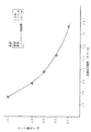
図3は、一例として、肉厚1mmの合成石英ガラス管を使用した放電灯のサイズが、内径13mm、管長154cm、フィラメント間距離147cmの物理的条件下で、電気的条件としてはランプ電流Iが1A(アンペア)で、約40kHzの電子バラストを使用する(つまりVf=10)の場合における、「電位傾度」と「185nm紫外線放射効率」の測定結果を示すもので、「電位傾度」の値を横軸にとり、それに対応する「185nm紫外線放射効率」の値を縦軸にとり、測定結果をプロットしたものである。ランプ電圧Vは、前述の通り冷却水の温度を変化させることで変化させた。図2によれば、「電位傾度」が約0.88(V/cm)のとき、「185nm紫外線放射効率」が最も高い値(約「6」)を示すことが判る。ここから判ることは、「185nm紫外線放射効率」がその最高値つまりピーク値(図2の例では約「6」)を含む適宜の許容範囲内に収まるように、物理的及び電気的諸条件を設定しさえすれば、185nm紫外線を効率よく放射できる放電灯および紫外線照射装置を提供することができる、ということである。この許容範囲としては、実際の紫外線照射状態を観察することにより、ピーク値の「185nm紫外線放射効率」の約6〜7割程度までは、許容範囲に含めることが適当であることが判明した。例えば、図3の例では、「185nm紫外線放射効率」の値が最低でも約3.6以上であれば、効率よい放射が得られているとみなせる。その場合、「電位傾度」が約0.72〜1.16程度の範囲内に収まるように諸条件が設定されればよいことが図から判明する。
【0028】
更に別の実測結果について説明する。図3と同様の管径13mm、管長154cm、フィラメント間距離147cmのサイズの放電灯において、ランプ電流Iを種々に異ならせて、各ランプ電流値における「185nm紫外線放射効率」がピーク値となる最適な電位傾度を探索した。その結果得られた各ランプ電流値(たて軸)における最適「電位傾度」(横軸)をプロットした図が、図4である。この図4から、最適「電位傾度」はほぼランプ電流値(I)の平方根(√I)に反比例していることが判る。
【0029】
以下同様にして、本実験に用いた上述した全てのサイズの放電灯について、「185nm紫外線放射効率」がピーク値となる最適な「電位傾度」を探索した結果、いずれの管径でも最適「電位傾度」はほぼ電流値(I)の平方根(√I)に反比例することを見出した。また、管径(D)をパラメータとして最適「電位傾度」をプロットした結果、図5に示すようにいずれの電流においても概ね管径(D)の平方根(√D)にも反比例することが判明した。即ち、内径(D)が8〜23mmの放電灯において、ランプ電流0.4 〜1.4 Aの範囲で動作させた場合に、最大の185nmの放射効率を得るための最適「電位傾度」は、管径(D)と電流(I)の平方根(√D及び√I)に反比例することを見出した。これは、高周波の電子バラストと商用周波数の電磁バラストのいずれであっても点灯電流のファクターを考慮しさえすれば、包含される結果となった。
【0030】
上記より、最適な「電位傾度」にあっては、「電位傾度」つまり「(V−Vf)/L」は、管径Dの平方根(√D)及びランプ電流Iの平方根(√I)に反比例する関係にあり、その比例定数をXとすると、下記のような関係式で表わせることになる。
(V−Vf)/L=X/(√D・√I)
前記図3の例の場合、内径D=13mm、ランプ電流I=1Aであったから、(√D・√I)は約3.605であり、「電位傾度」が上述した約0.72〜1.16程度の許容範囲内に収まるためには、比例定数Xは、ほぼ「2.6≦X≦4.2」の範囲の値をとればよいことになる。
【0031】
以上のような実験結果を考慮して、図1に示すような合成石英ガラスで構成した発光管バルブ11を用いた放電灯31において、合成石英ガラスからなる発光管バルブ11の内径D(単位はmm)のサイズは8mm以上とし、フィラメント21a,21bの間隔をL(単位はcm)、点灯時のランプ電圧をV(単位はV(ボルト))、ランプ電流をI(単位はA(アンペア))とするとき、各値の関係が次の関係式を有するように設定することが、185nm紫外線を効率良く放射するための条件とするのがよい、との結論に至った。
(V−Vf)/L=X/(√D・√I) ただし、2.6≦X≦4.2
ここで、前述の通り、点灯電源によって一義的に決まるファクターである陽極降下電圧Vfは、1kHz以上の高周波電源で点灯した場合はVf=10であり、1kHz未満の電源で点灯した場合はVf=50であるとする。
【0032】
このように、上述の実施例に係る放電灯31は、前記条件に基づき一例として、発光管バルブの内径13mm、フィラメント間距離153cmとして、発光管バルブ11の材質を合成石英ガラスにより構成した上で、図1に示されるように、前記発光管バルブ11内表面に金属酸化物(本実施例においては一例として、酸化アルミニウム)の薄膜44を形成したものである。
【0033】
次に、この放電灯31を長期間にわたって点灯実験して得られた紫外線照度維持率の測定結果について図6を参照して説明する。図において、横軸は点灯時間、たて軸は本発明による放電灯の照度の初期値を100%とした時の185nmと254nm波長の紫外線照度である。発光管バルブ11内表面に薄膜44を施した結果、254nmの波長域の紫外線照度の低下が殆ど見られず、前述の図9に示した従来の放電灯と比べて、照度維持率が飛躍的に向上しているのが判る。また、185nmの波長域の紫外線照度維持率も格段に向上しているのが判る。
【0034】
本発明に係る紫外線による液体処理装置つまり紫外線照射装置は、例えば半導体製造工程で使用される超純水の精製に利用されるもので、その場合、1年〜3年の長期連続運転に耐えるものでなければならない。本発明による放電灯を用いれば、TOC(Total Organic Carbon:全有機体炭素)分解処理能力の向上と、イオン交換樹脂の負担軽減との相乗効果を図ることができる。従って、本発明は半導体製造工程等で使用される超純水精製処理に最適である。もちろん、本発明に係る紫外線による液体処理装置は、半導体製造工程に限らず、飲料製造、食品製造、医療、水処理等、有機物の分解処理・殺菌・消毒等のために液体処理を施す汎ゆる分野で利用可能である。図7は、従来技術による放電灯を搭載した紫外線照射装置Bと本発明の実施例に述べた放電灯を搭載した紫外線照射装置Aについて、TOC濃度10ppbの原水を1ppb以下にできる処理能力を単位消費電力量当たりの流量で比較した実測データを示す図である。図は従来装置Bの初期値を100%として表示してある。従来装置Bと本発明装置Aとでは、まず初期において大きな性能差があり、使用時間が進むにつれて性能差が更に大きくなるのが判る。このTOC処理能力の向上は、185nmの紫外線放射効率及び維持率の向上によるものであるが、短波長域の紫外線の過多は、前述の通り、過剰な過酸化物を生成し、イオン交換樹脂の寿命劣化を招くことになるが、本発明にかかる放電灯を用いれば、254nmの紫外線の照度低下を抑制することで、イオン交換樹脂の負担を軽減することができる。
【0035】
図8は、従来技術による紫外線照射装置Bと本発明の実施例に述べた放電灯を使用した紫外線照射装置Aにおける、処理水の比抵抗値を、後段のイオン交換樹脂工程の出口で測定した結果である。図において、縦軸に比抵抗値を示し、横軸に点灯時間を示す。比抵抗値は過酸化物の濃度に依存しており、過酸化物の濃度が高いほど比抵抗値は低くなる。つまり、イオン交換樹脂の劣化により過酸化物漏洩が増すと、比抵抗値が低下するので、イオン交換樹脂出口における比抵抗値の推移は、イオン交換樹脂劣化のレベル指標となる。装置使用初期における比抵抗値は、従来装置B、本発明装置Aのいずれにおいても18MΩ強であったが、装置使用開始から一年後の時点で、従来装置Bの比抵抗値は、イオン交換樹脂更新の目安とされる16MΩ程度にまで低下した。これに対して、本発明装置Aにおいては、使用期間経過後も比抵抗値の低下は、極僅かであり、イオン交換樹脂への負担が軽減しているのが判る。これは、254nmの波長域の紫外線照度維持率の飛躍的向上により、過酸化物処理能力が維持されているためである。
【0036】
以上述べたように、本発明は、220nm以下の短波長域と254nmの紫外線を共存発光する放電灯において、発光管の内表面に金属酸化物の薄膜を形成し、254nmの紫外線照度維持率を高め、該放電灯からの紫外線によって処理対象液体の有機物分解等の処理を行うことで、意図しない中間生成物の分解を促進させるようにした発明である。上記実施例では、発光管を合成石英ガラスで構成し、波長185nmの紫外線を効率よく発光しうるような所定の条件でディメンションを決定した放電灯について説明したが、この場合は、特に絶大な作用効果を得ることができるのであるが、本発明の実施態様はこれに限らず、例えば、前記発光管の素材として通常の(天然)石英ガラスを用いた場合も同様の作用効果を得ることができる。また、放電灯のガラス内面に形成する薄膜として用いる金属酸化物は、一例として酸化アルミニウムを使用した例を説明したが、これに限らず、アルミニウム、ケイ素、カルシウム、マグネシウム、イットリウム、ジルコニウム及びハフニウムの中から選ばれた金属の少なくとも一種類以上の酸化物を主成分とするものであれば有効である。なお、放電灯の形態は、220nm以下の波長域と254nmの紫外線を共存発光する放電灯であれば、水銀と他の金属のアマルガムを封入したタイプの放電灯、フィラメントを常時加熱するコンテニュアスヒーティングタイプあるいはフィラメントとアノードの併設したタイプ等々、いずれの形態であっても本発明を適用することができ、同様の作用効果を得ることができる。
【0037】
【発明の効果】
以上の通り、本発明によれば、220nm以下の波長域と254nmの紫外線を共存発光する放電灯における254nmの紫外線照射維持率を著しく高め、同時に、220nm以下の紫外線の放射効率を向上し、照射維持率を高めることで、該放電灯を使用した液体処理装置及び方法において各設備機器の長寿命並びに省エネルギー・省メンテナンス効果を図ることができる。
【図面の簡単な説明】
【図1】 本発明に係る紫外線による液体処理装置で使用する放電灯の一実施例を示す側面断面略図。
【図2】 石英ガラスの組成として、ナトリウム(Na)、カリウム(K)、タとして製作した各種の放電灯を長期間にわたって点灯実験することで得られた紫外線強度維持率曲線を示すグラフ。
チタニウム(Ti)、鉄(Fe)の総含有量およびOH基の含有量をパラメー
【図3】 本発明で使用する放電灯の一実施例による実験結果に基づく「電位傾度」と「185nm紫外線放射効率」の関係を例示するグラフ。
【図4】 本発明で使用する放電灯の一実施例による実験結果に基づく「ランプ電流」と最適「電位傾度」との関係を例示するグラフ。
【図5】 本発明で使用する放電灯の一実施例による実験結果に基づくガラス管の内径と最適「電位傾度」との関係を、「ランプ電流」の各値に対応して、例示するグラフ。
【図6】 本発明で使用する放電灯の185nmと254nmの紫外線照射維持率の一例を示すグラフ。
【図7】 本発明に係る液体処理装置すなわち紫外線照射装置における時間経過に伴うTOC分解処理能力の変化の実験結果を、従来装置と比較して例示するグラフ。
【図8】 本発明に係る液体処理装置すなわち紫外線照射装置における時間経過に伴う、イオン交換樹脂出口での比抵抗値の推移を、従来装置と比較して例示するグラフ。
【図9】 従来技術の放電灯における185nmと254nmの紫外線照射維持率の一例を示すグラフ。
【図10】 従来の放電灯を使用した紫外線照射装置の一例を示す側面断面略図。
【符号の説明】
31 放電灯
11 発光管バルブ
21a,21b フィラメント
2a,2b シール部
3a,3b 口金部
22a〜22d インナーリード
31a,31b 電気端子[0001]
BACKGROUND OF THE INVENTION
The present invention relates to a liquid processing apparatus and method for performing processing such as decomposition of organic substances in a liquid using a discharge lamp that emits both short-wavelength ultraviolet light of 220 nm or less and ultraviolet light of 254 nm.
[0002]
[Prior art]
Since ultraviolet rays having a short wavelength region of 220 nm or less have strong energy, they are widely used such as decomposition of harmful substances and organic substances. FIG. 10 shows an example of a conventionally known closed type ultraviolet irradiation apparatus for liquid processing. The
[0003]
H2O + hν (185 nm) → H + OH radical
Cn Hm Ok + OH radical → CO, CO2, H2O
(N, m, k, are 1, 2, 3, ...)
[0004]
The decomposition of the organic matter is due to the action of ultraviolet rays in the short wavelength region of 185 nm, but the excess of ultraviolet rays in the short wavelength region is caused by hydrogen peroxide (H2O2), And various unintended peroxides are formed as intermediates. In order to remove such peroxides, a step of passing the liquid to be treated which has been subjected to the ultraviolet irradiation treatment through an ion exchange resin is provided after the ultraviolet irradiation treatment. Therefore, these peroxides are removed when the liquid to be treated passes through the ion exchange resin, but the excessive peroxide causes the life of the ion exchange resin to deteriorate.
[0005]
[Problem to be Solved by the Invention]
The present invention has been made in view of the above-described points, and an object of the present invention is to provide a liquid processing apparatus and method using ultraviolet rays capable of performing liquid processing in which generation of peroxide can be suppressed as much as possible. Accordingly, it is intended to provide a liquid processing apparatus and method that can extend the life of the ion exchange resin used in the latter stage of the ultraviolet irradiation treatment, and have a long life, energy saving, and maintenance.
[0006]
[Means for Solving the Problems]
The liquid treatment apparatus using ultraviolet light according to the present invention irradiates the liquid to be treated with ultraviolet light emitted from a discharge lamp that emits both ultraviolet light having a wavelength of 220 nm or less and ultraviolet light having a wavelength of 254 nm, and the ultraviolet light having a wavelength of 220 nm or less. In this liquid processing apparatus, the ultraviolet light having a wavelength of 220 nm or less dissociates water molecules in the liquid to be processed to generate OH radicals, and the generated OH radicals generate the OH radicals. It contributes to decomposing organic matter, and the ultraviolet ray having a wavelength of 254 nm contributes to decomposing a peroxide which is an intermediate generated in the liquid to be treated in the process of decomposing the organic matter by the ultraviolet ray having a wavelength of 220 nm or less. The discharge lamp includes a quartz glass arc tube having a metal oxide thin film formed on the inner surface thereof. Te prevent adsorption to the inner surface of the arc tube of mercuric oxide generated during lighting of the discharge lamp, with and prevent decrease in illuminance of ultraviolet rays having a wavelength of the 254nmThe arc tube of the discharge lamp is made of synthetic quartz glass having an inner diameter of 8 to 23 mm, and a pair of filaments are provided at both ends of the arc tube at intervals of L centimeters. The discharge lamp is operated at a lamp current of 0.4 to 1.4 amperes, and the lamp voltage V volt at the time of lighting, the lamp current I ampere, the distance L between filaments, and the inner diameter D millimeter of the discharge path And having the following relational expression.
(V−Vf) / L = X / (√D · √I) and
2.6 ≦ X ≦ 4.2.
However, Vf is a constant factor depending on the lighting power source. When the high-frequency power source is 1 kHz or higher, Vf = 10, and when the power source is less than 1 kHz, Vf = 50..
According to the present invention, ultraviolet rays having a wavelength of 220 nm or less dissociate water molecules in the liquid to be treated to generate OH radicals, and contribute to decomposing organic substances by the generated OH radicals, while 254 nm. UV light having a wavelength of 254 nm contributes to the decomposition of peroxides generated by excess OH radicals in the process of decomposing organic matter. Therefore, UV light having a wavelength of 254 nm is also useful, and is applied to the inner surface of the arc tube of a discharge lamp. By forming a thin film of metal oxide, it is possible to prevent mercury oxide generated during the operation of the discharge lamp from adsorbing to the inner surface of the arc tube, and to suppress the decrease in illuminance of useful ultraviolet light with a wavelength of 254 nm. Can do.
[0007]
In a discharge lamp that emits both ultraviolet light having a wavelength of 220 nm or less and ultraviolet light having a wavelength of 254 nm, ultraviolet light having a wavelength region of 220 nm or less is involved in the photochemical treatment for decomposing organic matter. On the other hand, ultraviolet rays in the wavelength region of 254 nm play an important role in the decomposition of peroxide, which is an intermediate, and reduce the burden on ion exchange resins used in the subsequent stage of ultraviolet irradiation treatment. By the way, although the ultraviolet illuminance of the discharge lamp decreases with the passage of time of use, the cause of the decrease in the ultraviolet illuminance differs between ultraviolet light having a short wavelength region of 220 nm or less and ultraviolet light having a wavelength region of 254 nm. The decrease in UV illuminance in the short wavelength region of 220 nm or less is due to the fact that the quartz glass forming the tube of the discharge lamp is exposed to UV rays and deteriorates, resulting in a decrease in UV transmittance. On the other hand, the decrease in the illuminance of ultraviolet rays in the wavelength region of 254 nm is caused by the fact that oxygen generated in the tube reacts with mercury during the operation of the discharge lamp, and the mercury oxide produced is adsorbed on the inner surface of the quartz glass, so This is due to the decline in rate. Therefore, as illustrated in FIG. 9, the ultraviolet illuminance maintaining characteristics are different between the ultraviolet light having a short wavelength region of 220 nm or less and the ultraviolet light having a wavelength region of 254 nm. 9 and after the C point where the maintenance factor of 254 nm falls below the ultraviolet illuminance maintenance factor of 220 nm or less (for example, 185 nm), it is considered that an increase in peroxide occurs. In contrast, according to the present invention, by forming a metal oxide thin film on the inner surface of the discharge lamp, it is possible to prevent mercury oxide generated during the operation of the discharge lamp from adsorbing on the inner surface of the arc tube. It is possible to suppress a decrease in illuminance of ultraviolet rays of 254 nm.
[0008]
The present invention also provides the liquid treatment described above.apparatusIn the discharge lamp arc tubeTubeHowever, starting from natural quartz or quartz sand, the total content of the four elements of sodium, potassium, titanium, and iron is 2.5 ppm (however, mass proportion) or less, and 10 ppm (however, mass proportion) or more From quartz glass containing OH groupsBecomeIt is characterized by that.
[0009]
In quartz glass starting from natural quartz or quartz sand, various substances are contained as impurities. Among these impurities, the presence of a large amount of four elements such as sodium (Na), potassium (K), titanium (Ti), and iron (Fe) causes a decrease in the transmittance of quartz glass. On the other hand, the presence of OH groups can mitigate the alteration of quartz glass. That is, silicon dioxide (SiO2) which is the main component of quartz glass.2) Group of “Si—O” is decomposed by ultraviolet energy to generate free Si which causes a decrease in transmittance, and the OH group recombines with free Si to “Si—OH”. It can suppress by becoming. As a result of experiments and research by the inventor, if the total content of these four elements is 2.5 ppm or less and contains 10 ppm or more of OH groups, the quartz glass deteriorates with time due to short wavelength ultraviolet rays. It turns out that it can be improved considerably. Therefore, by selecting or setting the material of the quartz glass in such a manner, it is possible to increase the illuminance maintenance rate of ultraviolet light in a short wavelength region of 220 nm or less, and the metal oxide is formed on the inner surface of the arc tube of such a high performance discharge lamp. By forming this thin film, the effect of suppressing a decrease in illuminance of 254 nm ultraviolet light is further exhibited.
[0010]
The present invention also provides the liquid treatment described above.apparatusIn the discharge lampThe tube of the arc tube, Inner diameter 8MmThru 23MmFrom synthetic quartz glassROf this arc tubeTubularL at both endsCentimeterA pair of filaments with a spacing ofThePrepared,The0.4 discharge lampAmpere~ 1.4AmpereThe lamp voltage VboltAnd the lamp current IAmpere, Interfilament distance LCentimeter, Inner diameter D of discharge pathMmHas the following relational expression.
(V−Vf) / L = X / (√D · √I) and
2.6 ≦ X ≦ 4.2.
However, Vf is a constant factor depending on the lighting power source, and Vf = 10 when lighting with a high-frequency power source of 1 kHz or more, and Vf = 50 when lighting with a power source of less than 1 kHz. Although details will be described later, by setting conditions as in the above relational expression, ultraviolet rays in a short wavelength region of 220 nm or less can be efficiently radiated, and the metal oxide is formed on the inner surface of the arc tube of such a high performance discharge lamp. By forming a thin film, the effect of suppressing a decrease in illuminance of ultraviolet light of 254 nm is further exhibited.
[0011]
In a preferred embodiment of the present invention, the metal oxide thin film formed on the inner surface of the arc tube of the discharge lamp is at least one metal selected from aluminum, silicon, calcium, magnesium, yttrium, zirconium and hafnium. The main component is the oxide. Since these metal oxides are excellent in heat resistance and scientifically stable, they effectively act to prevent adsorption of mercury oxide on the inner surface of the arc tube.
[0012]
Further, in the liquid treatment method using ultraviolet rays according to the present invention, the discharge target lamp is formed by forming a metal oxide thin film on the inner surface of the arc tube as described above. It is characterized by performing organic matter decomposition treatment.
[0013]
DETAILED DESCRIPTION OF THE INVENTION
Hereinafter, embodiments of the present invention will be described with reference to the accompanying drawings.
FIG. 1 shows an embodiment of a discharge lamp used in a liquid processing apparatus and method according to the present invention. First, the basic structure of the
The filaments 21a and 21b are formed, for example, by applying a barium oxide based emitter, and are held by inner leads 22a to 22d extending from the seal portions 2a and 2b, respectively. The base parts 3a and 3b are made of ceramic, and one base part 3a is provided with a pair of electrical terminals 31a and 31b. The seal portions 2a and 2b are electrically connected to the filaments 21a and 21b through the inner leads 22a to 22d, the molybdenum foils 24a to 24d, and the outer leads 25a, 25b and 26 while maintaining airtightness by the molybdenum foils 24a to 24d. It plays a role of electrically connecting the terminals 31a and 31d. The arc tube bulb 11 is filled with about 20 mg of mercury and about 400 Pa of rare gas.
In the example of the figure, as an example, the
[0014]
As described above, the ultraviolet illuminance of the discharge lamp decreases with the passage of time of use, and the decrease of the ultraviolet illuminance in the wavelength region of 254 nm is generated by the reaction of oxygen generated in the tube with the mercury during the operation of the discharge lamp. OxidationwaterThis is because silver is adsorbed on the inner surface of the glass and the ultraviolet transmittance of the quartz glass is lowered. This is because the ultraviolet light at 254 nm, which is the resonance emission of mercury, causes self-absorption due to the presence of mercury. When mercury oxide is adsorbed on the inner surface of the glass, the ultraviolet transmittance at 254 nm is selectively reduced. . In view of this point, the discharge lamp used in the present invention is characterized in that a
[0015]
In carrying out the present invention, the
[0016]
The material of the arc tube bulb 11 of the
First, an example in which the arc tube bulb 11 is made of fused silica glass will be described. For example, the quartz glass of the arc tube bulb 11 is made of natural quartz or quartz sand as a starting material, and consists of four types of sodium (Na), potassium (K), titanium (Ti), and iron (Fe). The total element content is 2.5 ppm or less, and it is made of gas fused quartz glass containing 10 ppm or more of OH groups. As described above, the quartz glass constituting the material of the arc tube bulb 11 of the
[0017]
FIG. 2 shows various discharge lamps manufactured with the total content of sodium (Na), potassium (K), titanium (Ti), iron (Fe) and the content of OH groups as parameters. It is a UV intensity maintenance rate curve obtained by carrying out lighting experiment over a period. The shape and dimensions of the discharge lamp are the same, the horizontal axis is the lighting time, and the vertical axis is the ultraviolet intensity at a wavelength of 185 nm when the initial value of the intensity of the discharge lamp according to the present invention is 100%. The composition conditions of the quartz glass in each discharge lamp corresponding to each curve A, B, C, D are as shown in the following table.
[0018]
[Table 1]
Curve Total content of Na, K, Ti and Fe OH group content
A 2.5ppm or less 100ppm
B 4.2ppm 100ppm
C 4.5ppm Less than 10ppm
D 6.4ppm Less than 10ppm
[0019]
Curve A has a total content of 4 elements of sodium (Na), potassium (K), titanium (Ti) and iron (Fe) as defined in this example of 2.5 ppm or less, and 10 ppm or more. In other words, the curves B, C, and D do not satisfy this condition. In FIG. 2, it is clear from the curve A that the best results are obtained. As shown in FIG. 2, the impurities of sodium (Na), potassium (K), titanium (Ti), and iron (Fe), which are impurities in quartz glass. By setting the total content of the seed elements and the content of the OH group according to the present invention, the ultraviolet illuminance maintenance rate in the short wavelength region over time can be greatly improved. In the experiment of FIG. 2, ozone is generated by a reaction to ultraviolet rays in the atmosphere, and if the generated ozone is interposed between the discharge lamp and the ultraviolet intensity meter, the measured value varies. Measurements were made directly on the outer surface.
[0020]
In the technical field such as organic matter decomposition treatment using ultraviolet rays to which the present invention is applied, regardless of the input density of the discharge lamp, it is generally assumed that the ultraviolet ray maintenance rate after one year of use is 70%. From the point of view of the design, the quartz glass having the composition that gives the result of curve A in FIG. 2 is effective, and the quartz glass having the composition giving the results of curves B, C, and D is clearly not effective. Recognize. Thus, if the total content of the four elements, which are impurities of quartz glass, sodium (Na), potassium (K), titanium (Ti), and iron (Fe) is “2.5 ppm or less”, 1 It is possible to ensure an ultraviolet ray maintenance rate of 70% or more after annual use. In addition, if it is annotated about content of OH group, less than 10 ppm is inadequate with respect to the recombination effect of Si-OH.
[0021]
In addition, the quartz glass made of the above-mentioned material can be used not only in the arc tube bulb of the discharge lamp itself, but also in any part, component, or apparatus that is used by being exposed to ultraviolet rays having a wavelength range of 220 nm or less. . For example, the quartz glass according to the present invention can be used as the material of the ultraviolet light transmissive glass wall in the outer tube (protective tube) 20 as shown in FIG. The outer tube (protection tube) for storing the discharge lamp, that is, the shape of the container is not limited to the cylindrical shape, and may be any shape.
Of course, the type of fused silica glass constituting the arc tube bulb 11 of the
[0022]
Furthermore, in another embodiment of the
[0023]
An example of setting conditions for the dimensions of the discharge lamp 31 (various sizes such as bulb inner diameter and distance between filaments) when the arc tube bulb 11 is made of synthetic quartz glass will be described. In the
(V−Vf) / L = X / (√D · √I) where 2.6 ≦ X ≦ 4.2
Here, Vf is an anode drop voltage, and is a factor (constant factor) that is uniquely determined by the lighting power source. When lighting with a high frequency power source of 1 kHz or more, Vf = 10 and when lighting with a power source of less than 1 kHz Let Vf = 50.
[0024]
Next, the basis for deriving the above relational expression as a condition for enabling efficient emission of ultraviolet light having a wavelength of 185 nm will be described.
The present inventors prepared a plurality of discharge lamps having various basic sizes with the same basic structure as the
[0025]
Under the above-mentioned conditions, various electric characteristics, that is, the lamp voltage V, the lamp current I, the lamp power, and the 185 nm ultraviolet intensity were measured while changing the temperature of the cooling water while keeping the current substantially constant. The reason for changing the temperature of the cooling water is to change the mercury vapor pressure. That is, the 185 nm ultraviolet radiation efficiency and electrical characteristics are considered to depend on the mercury vapor pressure, so that the relationship is clarified. By changing the temperature of the cooling water, the temperature of the coldest part where excess mercury stays was changed, and the vapor pressure of mercury was changed. Incidentally, since the lamp voltage V depends on the mercury vapor pressure in the lamp, that is, the evaporation amount, the lamp voltage V is variably set by changing the temperature of the coldest part. In a discharge lamp having a certain physical size, since the lamp current I is also a constant factor determined by the ballast, the factor that can influence the 185 nm ultraviolet intensity is mainly the lamp voltage V. Therefore, by changing the temperature of the cooling water, as a result, the value of the lamp voltage V is changed variously, the value of the lamp voltage V is measured, and the intensity of 185 nm ultraviolet rays is measured each time, whereby the physical The correlation between the 185 nm ultraviolet intensity and the lamp voltage V under the condition of the size and the predetermined lamp current I is found. Therefore, the measurement is performed as such.
[0026]
Based on this measurement result, for the 185 nm ultraviolet intensity, from the viewpoint of “ultraviolet intensity per power consumption”, the value of the measured 185 nm ultraviolet intensity is divided by the measured lamp power, and the quotient is calculated as “radiation efficiency”. It was used as an index (that is, “185 nm ultraviolet radiation efficiency”). As for the lamp voltage, from the viewpoint of “voltage per unit length”, a fixed value Vf (V) of anode fall voltage (Vf) is subtracted from the measured lamp voltage value V (V), and the solution is obtained. “V−Vf” was divided by the inter-filament distance L, and the quotient was “potential gradient” (that is, the lamp voltage per unit length of the inter-filament distance). That is, by converting the measured “185 nm ultraviolet intensity” and “lamp voltage V” into “185 nm ultraviolet radiation efficiency” and “potential gradient” (lamp voltage per unit length of distance between filaments), respectively, The value of “185 nm ultraviolet radiation efficiency” with respect to each value of “potential gradient” can be compared, and it is possible to grasp where the conditions of good radiation efficiency are. As described above, the anode drop voltage Vf was set to Vf = 10 when lit with a high frequency power source of 1 kHz or higher, and Vf = 50 when lit with a power source of less than 1 kHz.
[0027]
As an example, FIG. 3 shows a discharge lamp using a synthetic quartz glass tube having a wall thickness of 1 mm under the physical condition of an inner diameter of 13 mm, a tube length of 154 cm, and a distance between filaments of 147 cm. This shows the measurement results of “potential gradient” and “185 nm ultraviolet radiation efficiency” when an electronic ballast of about 40 kHz is used at 1 A (ampere) (that is, Vf = 10). The horizontal axis represents the value of “185 nm ultraviolet radiation efficiency”, and the vertical axis represents the measurement result. The lamp voltage V was changed by changing the temperature of the cooling water as described above. According to FIG. 2, it can be seen that when the “potential gradient” is about 0.88 (V / cm), the “185 nm ultraviolet radiation efficiency” shows the highest value (about “6”). It can be seen from this that the physical and electrical conditions are set so that the “185 nm ultraviolet radiation efficiency” falls within an appropriate allowable range including the maximum value, that is, the peak value (about “6” in the example of FIG. 2). As long as the setting is made, it is possible to provide a discharge lamp and an ultraviolet irradiation device capable of efficiently emitting 185 nm ultraviolet rays. By observing the actual ultraviolet irradiation state, it was found that it is appropriate to include about 60 to 70% of the peak value “185 nm ultraviolet radiation efficiency” as the allowable range. For example, in the example of FIG. 3, if the value of “185 nm ultraviolet radiation efficiency” is at least about 3.6 or more, it can be considered that efficient radiation is obtained. In this case, it is clear from the figure that various conditions should be set so that the “potential gradient” falls within a range of about 0.72 to 1.16.
[0028]
Still another measurement result will be described. In a discharge lamp having a tube diameter of 13 mm, a tube length of 154 cm, and a distance between filaments of 147 cm as in FIG. 3, the lamp current I is varied differently, and the “185 nm ultraviolet radiation efficiency” at each lamp current value reaches its peak value. The potential gradient was searched. FIG. 4 is a plot of the optimum “potential gradient” (horizontal axis) for each lamp current value (vertical axis) obtained as a result. FIG. 4 shows that the optimum “potential gradient” is almost inversely proportional to the square root (√I) of the lamp current value (I).
[0029]
Similarly, as a result of searching for the optimum “potential gradient” at which “185 nm ultraviolet radiation efficiency” has a peak value for the discharge lamps of all the sizes described above used in this experiment, the optimum “potential” is obtained for any tube diameter. It has been found that the “gradient” is approximately inversely proportional to the square root (√I) of the current value (I). In addition, as a result of plotting the optimum “potential gradient” with the tube diameter (D) as a parameter, it was found that, as shown in FIG. 5, the current is almost inversely proportional to the square root (√D) of the tube diameter (D). did. That is, in a discharge lamp having an inner diameter (D) of 8 to 23 mm, the optimum “potential gradient” for obtaining the maximum radiation efficiency of 185 nm when operated in the range of a lamp current of 0.4 to 1.4 A is It was found that it is inversely proportional to the square root (√D and √I) of the tube diameter (D) and the current (I). This has been included as long as the factor of the lighting current is taken into consideration, whether it is a high frequency electronic ballast or a commercial frequency electromagnetic ballast.
[0030]
From the above, in the optimal “potential gradient”, the “potential gradient”, that is, “(V−Vf) / L” is the square root (√D) of the tube diameter D and the square root (√I) of the lamp current I. If the proportionality constant is X, it can be expressed by the following relational expression.
(V−Vf) / L = X / (√D · √I)
In the example of FIG. 3, since the inner diameter D = 13 mm and the lamp current I = 1 A, (√D · √I) is about 3.605, and the “potential gradient” is about 0.72-1 as described above. In order to be within the allowable range of about .16, the proportionality constant X should be approximately in the range of “2.6 ≦ X ≦ 4.2”.
[0031]
In consideration of the above experimental results, in the
(V−Vf) / L = X / (√D · √I) where 2.6 ≦ X ≦ 4.2
Here, as described above, the anode drop voltage Vf, which is a factor that is uniquely determined by the lighting power source, is Vf = 10 when lighted by a high frequency power source of 1 kHz or more, and Vf = 10 when lighted by a power source of less than 1 kHz. Let it be 50.
[0032]
As described above, the
[0033]
Next, the measurement result of the ultraviolet illuminance maintenance rate obtained through an experiment of lighting the
[0034]
The liquid processing apparatus using ultraviolet rays, that is, the ultraviolet irradiation apparatus according to the present invention is used for purifying ultrapure water used in, for example, a semiconductor manufacturing process, and in such a case, can withstand long-term continuous operation for 1 to 3 years. Must. By using the discharge lamp according to the present invention, it is possible to achieve a synergistic effect of improving the TOC (Total Organic Carbon) decomposition treatment capability and reducing the burden on the ion exchange resin. Therefore, the present invention is optimal for ultrapure water purification processing used in semiconductor manufacturing processes and the like. Of course, the liquid processing apparatus using ultraviolet rays according to the present invention is not limited to the semiconductor manufacturing process, but is a general process for performing liquid processing for beverage decomposition, sterilization, disinfection, etc., such as beverage manufacturing, food manufacturing, medical treatment, and water processing. Available in the field. FIG. 7 shows a unit of processing capacity capable of reducing raw water having a TOC concentration of 10 ppb to 1 ppb or less for the ultraviolet irradiation apparatus B equipped with a discharge lamp according to the prior art and the ultraviolet irradiation apparatus A equipped with the discharge lamp described in the embodiment of the present invention. It is a figure which shows the actual measurement data compared with the flow volume per power consumption. In the figure, the initial value of the conventional apparatus B is displayed as 100%. It can be seen that there is a large performance difference between the conventional apparatus B and the apparatus A of the present invention at the beginning, and the performance difference further increases as the usage time advances. This improvement in the TOC processing capacity is due to the improvement in ultraviolet radiation efficiency and maintenance rate of 185 nm. However, as described above, the excessive amount of ultraviolet rays in the short wavelength region generates excessive peroxide, Although it will lead to life deterioration, if the discharge lamp concerning this invention is used, the burden of an ion exchange resin can be reduced by suppressing the illumination intensity fall of 254 nm ultraviolet-ray.
[0035]
In FIG. 8, the specific resistance value of the treated water in the ultraviolet irradiation device A using the ultraviolet irradiation device B according to the prior art and the discharge lamp described in the embodiment of the present invention was measured at the outlet of the subsequent ion exchange resin process. It is a result. In the figure, the vertical axis represents the specific resistance value, and the horizontal axis represents the lighting time. The specific resistance value depends on the peroxide concentration. The higher the peroxide concentration, the lower the specific resistance value. That is, if the peroxide leakage increases due to the deterioration of the ion exchange resin, the specific resistance value decreases, so the transition of the specific resistance value at the ion exchange resin outlet becomes a level index of the ion exchange resin deterioration. The specific resistance value at the initial stage of use of the apparatus was slightly over 18 MΩ in both the conventional apparatus B and the apparatus A of the present invention. However, at one year after the start of use of the apparatus, the specific resistance value of the conventional apparatus B is It decreased to about 16 MΩ, which is a standard for resin renewal. On the other hand, in the device A of the present invention, the decrease in specific resistance value is negligible even after the period of use, and it can be seen that the burden on the ion exchange resin is reduced. This is because the peroxide processing capability is maintained by the dramatic improvement in the ultraviolet illuminance maintenance rate in the wavelength region of 254 nm.
[0036]
As described above, according to the present invention, in a discharge lamp that emits light in the short wavelength region of 220 nm or less and ultraviolet light of 254 nm, a thin film of metal oxide is formed on the inner surface of the arc tube, and the ultraviolet illuminance maintenance rate of 254 nm is achieved. It is an invention that promotes decomposition of an unintended intermediate product by performing processing such as organic matter decomposition of the liquid to be processed with ultraviolet rays from the discharge lamp. In the above-described embodiment, the discharge lamp has been described in which the arc tube is made of synthetic quartz glass and the dimensions are determined under a predetermined condition such that the ultraviolet ray having a wavelength of 185 nm can be efficiently emitted. Although the effect can be obtained, the embodiment of the present invention is not limited to this. For example, the same effect can be obtained when normal (natural) quartz glass is used as the material of the arc tube. . In addition, the metal oxide used as the thin film formed on the glass inner surface of the discharge lamp has been described by way of example using aluminum oxide as an example, but is not limited thereto, and is not limited to aluminum, silicon, calcium, magnesium, yttrium, zirconium, and hafnium. It is effective if it contains at least one oxide of a metal selected from among the main components. If the discharge lamp is a discharge lamp that emits light in the wavelength region of 220 nm or less and ultraviolet light of 254 nm, it is a type of discharge lamp in which mercury and other metal amalgam are enclosed, and a continuous heating filament. The present invention can be applied to any type, such as a heating type or a type in which a filament and an anode are provided, and similar effects can be obtained.
[0037]
【The invention's effect】
As described above, according to the present invention, the ultraviolet irradiation maintenance rate of 254 nm in the discharge lamp coexisting with the wavelength region of 220 nm or less and the ultraviolet ray of 254 nm is remarkably increased, and at the same time, the radiation efficiency of the ultraviolet ray of 220 nm or less is improved, By increasing the maintenance rate, it is possible to achieve a long life of each equipment and energy saving / maintenance effect in the liquid processing apparatus and method using the discharge lamp.
[Brief description of the drawings]
FIG. 1 is a schematic side sectional view showing an embodiment of a discharge lamp used in a liquid processing apparatus using ultraviolet rays according to the present invention.
FIG. 2 is a graph showing a UV intensity maintenance rate curve obtained by conducting a long-term lighting experiment on various discharge lamps manufactured as sodium (Na), potassium (K), and ta as the composition of quartz glass.
The total content of titanium (Ti) and iron (Fe) and the content of OH groups are parameterized.
FIG. 3 is a graph illustrating the relationship between “potential gradient” and “185 nm ultraviolet radiation efficiency” based on the experimental results of one embodiment of a discharge lamp used in the present invention.
FIG. 4 is a graph illustrating the relationship between the “lamp current” and the optimum “potential gradient” based on the experimental results of one embodiment of the discharge lamp used in the present invention.
FIG. 5 is a graph illustrating the relationship between the inner diameter of the glass tube and the optimum “potential gradient” based on the experimental results of one embodiment of the discharge lamp used in the present invention, corresponding to each value of “lamp current”; .
FIG. 6 is a graph showing an example of an ultraviolet irradiation maintenance rate of 185 nm and 254 nm of a discharge lamp used in the present invention.
FIG. 7 is a graph illustrating an experimental result of a change in TOC decomposition processing capacity with time in a liquid processing apparatus, that is, an ultraviolet irradiation apparatus according to the present invention, as compared with a conventional apparatus.
FIG. 8 is a graph illustrating the transition of the specific resistance value at the ion exchange resin outlet over time in the liquid processing apparatus, that is, the ultraviolet irradiation apparatus according to the present invention, as compared with the conventional apparatus.
FIG. 9 is a graph showing an example of an ultraviolet irradiation maintenance rate of 185 nm and 254 nm in a conventional discharge lamp.
FIG. 10 is a schematic side sectional view showing an example of an ultraviolet irradiation device using a conventional discharge lamp.
[Explanation of symbols]
31 Discharge lamp
11 Arc tube bulb
21a, 21b Filament
2a, 2b Seal part
3a, 3b Base part
22a-22d Inner lead
31a, 31b Electrical terminal
Claims (4)
前記220nm以下の波長の紫外線は処理対象液体中の水分子を解離してOHラジカルを生成し、該生成されたOHラジカルによって有機物を分解することに寄与し、前記254nmの波長の紫外線は、前記220nm以下の波長の紫外線による有機物分解過程で前記処理対象液体中に発生した中間体である過酸化物を分解するのに寄与し、
前記放電灯は、内表面に金属酸化物の薄膜が形成された石英ガラス製発光管を備えており、該金属酸化物の薄膜によって当該放電灯の点灯中に生成される酸化水銀の当該発光管の内表面への吸着を防止し、もって、前記254nmの波長の紫外線の照度低下を防ぐようにしたものであり、
前記放電灯の発光管の管体が、内径8ミリメートル乃至23ミリメートルの合成石英ガラスからなり、この発光管の管体の両端にLセンチメートルの間隔で一対のフィラメントを備え、該放電灯を0.4アンペア〜1.4アンペアのランプ電流で動作させ、点灯時のランプ電圧Vボルトと、ランプ電流Iアンペア、フィラメント間距離Lセンチメートル、放電路の内径Dミリメートルについて、次なる関係式を有することを特徴とする液体処理装置。
(V−Vf)/L=X/(√D・√I) かつ、
2.6 ≦ X ≦ 4.2。
ただし、Vfは点灯電源に依存する定数要因で、1kHZ以上の高周波電源で点灯した場合はVf=10とし、1kHZ未満の電源で点灯した場合はVf=50とする。The liquid to be treated is irradiated with ultraviolet light emitted from a discharge lamp that emits both ultraviolet light having a wavelength of 220 nm or less and ultraviolet light having a wavelength of 254 nm, and the organic matter is decomposed by the ultraviolet light having a wavelength of 220 nm or less. A liquid processing apparatus,
The ultraviolet rays having a wavelength of 220 nm or less dissociate water molecules in the liquid to be treated to generate OH radicals, and contribute to decomposing organic substances by the generated OH radicals. The ultraviolet rays having a wavelength of 254 nm are Contributes to decomposing peroxide, which is an intermediate generated in the liquid to be treated in the process of decomposing organic matter by ultraviolet light having a wavelength of 220 nm or less,
The discharge lamp includes an arc tube made of quartz glass having a metal oxide thin film formed on an inner surface thereof, and the arc tube of mercury oxide generated during lighting of the discharge lamp by the metal oxide thin film. Adsorbing to the inner surface of the material, and thus preventing a decrease in illuminance of the ultraviolet light having the wavelength of 254 nm ,
The arc tube of the discharge lamp is made of synthetic quartz glass having an inner diameter of 8 to 23 mm, and a pair of filaments are provided at both ends of the arc tube at intervals of L centimeters. Operated with a lamp current of .4 amperes to 1.4 amperes, the lamp voltage V volt at lighting, the lamp current I ampere, the distance L between filaments, and the inner diameter D millimeter of the discharge path have the following relational expressions. A liquid processing apparatus.
(V−Vf) / L = X / (√D · √I) and
2.6 ≦ X ≦ 4.2.
However, Vf is a constant factor depending on the lighting power source, and Vf = 10 when lighting with a high-frequency power source of 1 kHz or more, and Vf = 50 when lighting with a power source of less than 1 kHz .
前記液体処理装置を使用して、処理対象である水の中に含まれる有機物を分解処理する第1工程と、
前記第1工程で処理された前記水を、前記紫外線液体処理装置の後段に設けられたイオン交換樹脂にて処理する第2工程と
を具備し、不純物の極めて少ない超純水を製造することを特徴とする紫外線液体処理方法。An ultraviolet liquid processing method performed using a liquid processing apparatus according to any one of claims 1 to 3,
A first step of decomposing organic matter contained in water to be treated using the liquid treatment apparatus;
A second step of treating the water treated in the first step with an ion exchange resin provided at a subsequent stage of the ultraviolet liquid treatment apparatus, and producing ultrapure water with very few impurities An ultraviolet liquid processing method characterized by the above.
Priority Applications (2)
| Application Number | Priority Date | Filing Date | Title |
|---|---|---|---|
| JP2001244654A JP4865965B2 (en) | 2001-08-10 | 2001-08-10 | Liquid treatment apparatus and method using ultraviolet rays |
| TW91123626A TWI234180B (en) | 2001-08-10 | 2002-10-15 | Ultraviolet-ray liquid treating apparatus |
Applications Claiming Priority (1)
| Application Number | Priority Date | Filing Date | Title |
|---|---|---|---|
| JP2001244654A JP4865965B2 (en) | 2001-08-10 | 2001-08-10 | Liquid treatment apparatus and method using ultraviolet rays |
Publications (3)
| Publication Number | Publication Date |
|---|---|
| JP2003059453A JP2003059453A (en) | 2003-02-28 |
| JP2003059453A5 JP2003059453A5 (en) | 2005-10-13 |
| JP4865965B2 true JP4865965B2 (en) | 2012-02-01 |
Family
ID=19074553
Family Applications (1)
| Application Number | Title | Priority Date | Filing Date |
|---|---|---|---|
| JP2001244654A Expired - Lifetime JP4865965B2 (en) | 2001-08-10 | 2001-08-10 | Liquid treatment apparatus and method using ultraviolet rays |
Country Status (2)
| Country | Link |
|---|---|
| JP (1) | JP4865965B2 (en) |
| TW (1) | TWI234180B (en) |
Families Citing this family (5)
| Publication number | Priority date | Publication date | Assignee | Title |
|---|---|---|---|---|
| JP4516251B2 (en) * | 2001-11-07 | 2010-08-04 | 株式会社日本フォトサイエンス | Ultraviolet irradiation device and operation method thereof |
| US6841939B2 (en) * | 2002-04-08 | 2005-01-11 | General Electric Company | Fluorescent lamp |
| JP5126965B2 (en) * | 2007-12-18 | 2013-01-23 | 株式会社東通研 | Water-cooled UV irradiation device |
| JP6872787B2 (en) * | 2017-04-13 | 2021-05-19 | 株式会社東通研 | Protective jacket for UV irradiation |
| CN114885856B (en) * | 2022-05-30 | 2023-04-25 | 河北省畜牧总站(河北省畜牧业监测预警服务中心) | Closed chicken coop deodorization and sterilization lamp and chicken coop provided with same |
Family Cites Families (6)
| Publication number | Priority date | Publication date | Assignee | Title |
|---|---|---|---|---|
| JPH06310096A (en) * | 1993-04-27 | 1994-11-04 | Hitachi Ltd | Low-pressure mercury vapor lamp device |
| JP2980510B2 (en) * | 1994-01-28 | 1999-11-22 | 信越石英株式会社 | High purity silica glass for ultraviolet lamp and method for producing the same |
| JPH09276858A (en) * | 1996-04-16 | 1997-10-28 | Nippon Photo Sci:Kk | Ultraviolet toc decomposing apparatus |
| JPH11265687A (en) * | 1998-03-18 | 1999-09-28 | Toray Ind Inc | Multiple tube type discharge lamp and photochemical reacting device |
| JP2000285802A (en) * | 1999-03-31 | 2000-10-13 | Iwasaki Electric Co Ltd | Manufacture of low-pressure mercury discharge lamp and, low-pressure mercury discharge lamp |
| JP3362840B2 (en) * | 1999-04-08 | 2003-01-07 | 日本電気株式会社 | Treatment method and treatment device for wastewater containing hydrogen peroxide |
-
2001
- 2001-08-10 JP JP2001244654A patent/JP4865965B2/en not_active Expired - Lifetime
-
2002
- 2002-10-15 TW TW91123626A patent/TWI234180B/en not_active IP Right Cessation
Also Published As
| Publication number | Publication date |
|---|---|
| JP2003059453A (en) | 2003-02-28 |
| TWI234180B (en) | 2005-06-11 |
Similar Documents
| Publication | Publication Date | Title |
|---|---|---|
| JP3563373B2 (en) | Discharge lamp, ultraviolet irradiation device, and operation method thereof | |
| JP4865965B2 (en) | Liquid treatment apparatus and method using ultraviolet rays | |
| TW570816B (en) | Ultraviolet ray irradiation device and operation method thereof | |
| KR100723124B1 (en) | Liquid treatment apparatus and method with ultraviolet light | |
| CN1502563A (en) | Ultraviolet ray device for treating liquid and method thereof | |
| WO2002024587A1 (en) | Quartz glass for short wave length ultraviolet ray, discharge lamp using the same, container therefor and ultraviolet irradiation apparatus | |
| JP4959072B2 (en) | Photochemical reaction processing apparatus and photochemical reaction processing method | |
| JP4475171B2 (en) | Flash lamp | |
| JPH1069886A (en) | Mercury vapor discharge lamp | |
| US6538384B2 (en) | Discharge lamp having discharge space with specific fill concentration | |
| JPH1021880A (en) | Discharge lamp, irradiation device, sterilizing device, and water treatment equipment | |
| KR100764332B1 (en) | Photochemical reaction treatment apparatus and photochemical reaction treatment method | |
| CN1298422C (en) | Photochemical reaction device and process method thereof | |
| JPH0871546A (en) | Ultraviolet irradiation apparatus for treating liquid | |
| JP3198519B2 (en) | UV irradiation device | |
| JP2022071472A (en) | Liquid treatment apparatus | |
| JPH06231733A (en) | Dielectric barrier discharge lamp | |
| JPH11300344A (en) | Bactericidal lamp and bactericidal lamp device | |
| JPH0745238A (en) | Method and device for lighting low pressure mercury lamp and ultraviolet irradiating device using this low pressure mercury lamp | |
| JPH073782B2 (en) | High output sterilization lamp | |
| JP2009238462A (en) | Low pressure mercury discharge lamp |
Legal Events
| Date | Code | Title | Description |
|---|---|---|---|
| A521 | Written amendment |
Free format text: JAPANESE INTERMEDIATE CODE: A523 Effective date: 20050603 |
|
| A621 | Written request for application examination |
Free format text: JAPANESE INTERMEDIATE CODE: A621 Effective date: 20050603 |
|
| A977 | Report on retrieval |
Free format text: JAPANESE INTERMEDIATE CODE: A971007 Effective date: 20061025 |
|
| A131 | Notification of reasons for refusal |
Free format text: JAPANESE INTERMEDIATE CODE: A131 Effective date: 20061031 |
|
| A521 | Written amendment |
Free format text: JAPANESE INTERMEDIATE CODE: A523 Effective date: 20061231 |
|
| A131 | Notification of reasons for refusal |
Free format text: JAPANESE INTERMEDIATE CODE: A131 Effective date: 20080624 |
|
| A521 | Written amendment |
Free format text: JAPANESE INTERMEDIATE CODE: A523 Effective date: 20080825 |
|
| A02 | Decision of refusal |
Free format text: JAPANESE INTERMEDIATE CODE: A02 Effective date: 20090908 |
|
| A521 | Written amendment |
Free format text: JAPANESE INTERMEDIATE CODE: A523 Effective date: 20091208 |
|
| A521 | Written amendment |
Free format text: JAPANESE INTERMEDIATE CODE: A523 Effective date: 20100204 |
|
| A911 | Transfer to examiner for re-examination before appeal (zenchi) |
Free format text: JAPANESE INTERMEDIATE CODE: A911 Effective date: 20100210 |
|
| A912 | Re-examination (zenchi) completed and case transferred to appeal board |
Free format text: JAPANESE INTERMEDIATE CODE: A912 Effective date: 20100430 |
|
| A521 | Written amendment |
Free format text: JAPANESE INTERMEDIATE CODE: A523 Effective date: 20110826 |
|
| A01 | Written decision to grant a patent or to grant a registration (utility model) |
Free format text: JAPANESE INTERMEDIATE CODE: A01 |
|
| A61 | First payment of annual fees (during grant procedure) |
Free format text: JAPANESE INTERMEDIATE CODE: A61 Effective date: 20111111 |
|
| FPAY | Renewal fee payment (event date is renewal date of database) |
Free format text: PAYMENT UNTIL: 20141118 Year of fee payment: 3 |
|
| R150 | Certificate of patent or registration of utility model |
Ref document number: 4865965 Country of ref document: JP Free format text: JAPANESE INTERMEDIATE CODE: R150 Free format text: JAPANESE INTERMEDIATE CODE: R150 |
|
| R250 | Receipt of annual fees |
Free format text: JAPANESE INTERMEDIATE CODE: R250 |
|
| R250 | Receipt of annual fees |
Free format text: JAPANESE INTERMEDIATE CODE: R250 |
|
| R250 | Receipt of annual fees |
Free format text: JAPANESE INTERMEDIATE CODE: R250 |
|
| R250 | Receipt of annual fees |
Free format text: JAPANESE INTERMEDIATE CODE: R250 |
|
| R250 | Receipt of annual fees |
Free format text: JAPANESE INTERMEDIATE CODE: R250 |
|
| R250 | Receipt of annual fees |
Free format text: JAPANESE INTERMEDIATE CODE: R250 |
|
| R250 | Receipt of annual fees |
Free format text: JAPANESE INTERMEDIATE CODE: R250 |
|
| EXPY | Cancellation because of completion of term |