JP4864319B2 - Surgical instruments adapted to apply multiple surgical fasteners to body tissue - Google Patents
Surgical instruments adapted to apply multiple surgical fasteners to body tissue Download PDFInfo
- Publication number
- JP4864319B2 JP4864319B2 JP2004380129A JP2004380129A JP4864319B2 JP 4864319 B2 JP4864319 B2 JP 4864319B2 JP 2004380129 A JP2004380129 A JP 2004380129A JP 2004380129 A JP2004380129 A JP 2004380129A JP 4864319 B2 JP4864319 B2 JP 4864319B2
- Authority
- JP
- Japan
- Prior art keywords
- knife
- cartridge housing
- anvil
- firing
- surgical
- Prior art date
- Legal status (The legal status is an assumption and is not a legal conclusion. Google has not performed a legal analysis and makes no representation as to the accuracy of the status listed.)
- Active
Links
- 238000010304 firing Methods 0.000 claims abstract description 134
- 230000007246 mechanism Effects 0.000 claims abstract description 48
- 239000012636 effector Substances 0.000 claims abstract description 42
- 238000005520 cutting process Methods 0.000 claims abstract description 12
- 239000004033 plastic Substances 0.000 claims description 7
- 229910052751 metal Inorganic materials 0.000 claims description 4
- 239000002184 metal Substances 0.000 claims description 4
- 238000000034 method Methods 0.000 description 10
- 230000008569 process Effects 0.000 description 10
- 238000003780 insertion Methods 0.000 description 9
- 230000037431 insertion Effects 0.000 description 9
- 229910052782 aluminium Inorganic materials 0.000 description 4
- XAGFODPZIPBFFR-UHFFFAOYSA-N aluminium Chemical compound [Al] XAGFODPZIPBFFR-UHFFFAOYSA-N 0.000 description 4
- 230000005540 biological transmission Effects 0.000 description 3
- 238000001125 extrusion Methods 0.000 description 3
- 238000004519 manufacturing process Methods 0.000 description 3
- 210000003813 thumb Anatomy 0.000 description 3
- 229910017052 cobalt Inorganic materials 0.000 description 2
- 239000010941 cobalt Substances 0.000 description 2
- GUTLYIVDDKVIGB-UHFFFAOYSA-N cobalt atom Chemical compound [Co] GUTLYIVDDKVIGB-UHFFFAOYSA-N 0.000 description 2
- 238000003745 diagnosis Methods 0.000 description 2
- 210000003811 finger Anatomy 0.000 description 2
- 230000003993 interaction Effects 0.000 description 2
- 238000003754 machining Methods 0.000 description 2
- 230000005855 radiation Effects 0.000 description 2
- 230000004044 response Effects 0.000 description 2
- 230000001954 sterilising effect Effects 0.000 description 2
- 238000004659 sterilization and disinfection Methods 0.000 description 2
- 125000002066 L-histidyl group Chemical group [H]N1C([H])=NC(C([H])([H])[C@](C(=O)[*])([H])N([H])[H])=C1[H] 0.000 description 1
- 230000009471 action Effects 0.000 description 1
- 210000002255 anal canal Anatomy 0.000 description 1
- 230000009286 beneficial effect Effects 0.000 description 1
- 238000010276 construction Methods 0.000 description 1
- 238000002224 dissection Methods 0.000 description 1
- 230000000694 effects Effects 0.000 description 1
- 208000014674 injury Diseases 0.000 description 1
- 230000014759 maintenance of location Effects 0.000 description 1
- 230000004048 modification Effects 0.000 description 1
- 238000012986 modification Methods 0.000 description 1
- 239000002991 molded plastic Substances 0.000 description 1
- 210000000214 mouth Anatomy 0.000 description 1
- 238000002271 resection Methods 0.000 description 1
- 230000000717 retained effect Effects 0.000 description 1
- 238000007789 sealing Methods 0.000 description 1
- 238000000926 separation method Methods 0.000 description 1
- 229910001220 stainless steel Inorganic materials 0.000 description 1
- 239000010935 stainless steel Substances 0.000 description 1
- 210000002784 stomach Anatomy 0.000 description 1
- 238000003860 storage Methods 0.000 description 1
- 230000008733 trauma Effects 0.000 description 1
- 239000013585 weight reducing agent Substances 0.000 description 1
Images


Classifications
-
- A—HUMAN NECESSITIES
- A61—MEDICAL OR VETERINARY SCIENCE; HYGIENE
- A61B—DIAGNOSIS; SURGERY; IDENTIFICATION
- A61B17/00—Surgical instruments, devices or methods, e.g. tourniquets
- A61B17/068—Surgical staplers, e.g. containing multiple staples or clamps
- A61B17/072—Surgical staplers, e.g. containing multiple staples or clamps for applying a row of staples in a single action, e.g. the staples being applied simultaneously
-
- A—HUMAN NECESSITIES
- A61—MEDICAL OR VETERINARY SCIENCE; HYGIENE
- A61B—DIAGNOSIS; SURGERY; IDENTIFICATION
- A61B17/00—Surgical instruments, devices or methods, e.g. tourniquets
- A61B2017/0023—Surgical instruments, devices or methods, e.g. tourniquets disposable
-
- A—HUMAN NECESSITIES
- A61—MEDICAL OR VETERINARY SCIENCE; HYGIENE
- A61B—DIAGNOSIS; SURGERY; IDENTIFICATION
- A61B17/00—Surgical instruments, devices or methods, e.g. tourniquets
- A61B17/068—Surgical staplers, e.g. containing multiple staples or clamps
- A61B17/072—Surgical staplers, e.g. containing multiple staples or clamps for applying a row of staples in a single action, e.g. the staples being applied simultaneously
- A61B2017/07214—Stapler heads
- A61B2017/07221—Stapler heads curved
-
- A—HUMAN NECESSITIES
- A61—MEDICAL OR VETERINARY SCIENCE; HYGIENE
- A61B—DIAGNOSIS; SURGERY; IDENTIFICATION
- A61B17/00—Surgical instruments, devices or methods, e.g. tourniquets
- A61B17/068—Surgical staplers, e.g. containing multiple staples or clamps
- A61B17/072—Surgical staplers, e.g. containing multiple staples or clamps for applying a row of staples in a single action, e.g. the staples being applied simultaneously
- A61B2017/07214—Stapler heads
- A61B2017/07271—Stapler heads characterised by its cartridge
-
- A—HUMAN NECESSITIES
- A61—MEDICAL OR VETERINARY SCIENCE; HYGIENE
- A61B—DIAGNOSIS; SURGERY; IDENTIFICATION
- A61B17/00—Surgical instruments, devices or methods, e.g. tourniquets
- A61B17/068—Surgical staplers, e.g. containing multiple staples or clamps
- A61B17/072—Surgical staplers, e.g. containing multiple staples or clamps for applying a row of staples in a single action, e.g. the staples being applied simultaneously
- A61B2017/07214—Stapler heads
- A61B2017/07285—Stapler heads characterised by its cutter
-
- A—HUMAN NECESSITIES
- A61—MEDICAL OR VETERINARY SCIENCE; HYGIENE
- A61B—DIAGNOSIS; SURGERY; IDENTIFICATION
- A61B90/00—Instruments, implements or accessories specially adapted for surgery or diagnosis and not covered by any of the groups A61B1/00 - A61B50/00, e.g. for luxation treatment or for protecting wound edges
- A61B90/03—Automatic limiting or abutting means, e.g. for safety
- A61B2090/038—Automatic limiting or abutting means, e.g. for safety during shipment
-
- A—HUMAN NECESSITIES
- A61—MEDICAL OR VETERINARY SCIENCE; HYGIENE
- A61B—DIAGNOSIS; SURGERY; IDENTIFICATION
- A61B90/00—Instruments, implements or accessories specially adapted for surgery or diagnosis and not covered by any of the groups A61B1/00 - A61B50/00, e.g. for luxation treatment or for protecting wound edges
- A61B90/08—Accessories or related features not otherwise provided for
- A61B2090/0814—Preventing re-use
Abstract
Description
本発明は、ステープルを用いた切除術によって処置された病状の診断および治療に用いるのに適合された手術用ステープリングおよび切開器具に関する。より詳しく言うと、本発明は手術用ステープリングおよび切開器具のカートリッジモジュールと共に用いるための発射機構に関する。 The present invention relates to surgical stapling and cutting instruments adapted for use in the diagnosis and treatment of medical conditions treated by excision using staples. More particularly, the present invention relates to a firing mechanism for use with surgical stapling and a cartridge module of an incision instrument.
手術用ステープリングおよび切開器具はステープルを用いた切除術によって処置された病状の診断および治療で広く用いられている。手術用ステープリングおよび切開器具は、肛門管、口、胃、およびサービスアクセス(service accesses)を介して導入された機械的な縫合器具を内腔を通して利用するための機構を提供する。手術用ステープリングおよび切開器具は直腸の病状に最も広く用いられているが、手術用ステープリングおよび切開器具はさまざまな環境で用いられてもよい。 Surgical stapling and lancing instruments are widely used in the diagnosis and treatment of medical conditions treated by staple resection. Surgical stapling and dissection instruments provide a mechanism for utilizing mechanical suture instruments introduced through the lumen, via the anal canal, mouth, stomach, and service accesses. Although surgical stapling and cutting instruments are most widely used for rectal medical conditions, surgical stapling and cutting instruments may be used in a variety of environments.
長年に亘って、手術用ステープリングおよび切開器具が開発されてきた。これらの手術用器具は一般的に支持フレーム、支持フレームに取り付けられたアンビル、および複数のステープルを保持するカートリッジハウジングを含んでいる。これらの手術用器具は全てのステープルをアンビルに向けて同時に押出して組織を一体に縫合するほぼB形の形状をステープルに与えるカートリッジハウジング内のドライバーさらに含んでいる。さらに、これらの手術用器具はカートッリジハウジングおよびアンビルの間に組織を受け入れるためのアンビルから離れた位置から組織がアンビルとカートリッジハウジングの間で締めつけられる閉じた位置へカートリッジハウジングを動かすための接近機構を含んでいる。最後に、これらの手術用器具はドライバーを前方に動かしてアンビルに対してステープルを押しつけてステープルに形を与える発射機構を含んでいる。 Over the years, surgical stapling and lancing instruments have been developed. These surgical instruments generally include a support frame, an anvil attached to the support frame, and a cartridge housing that holds a plurality of staples. These surgical instruments further include a driver in the cartridge housing that gives the staples a generally B-shaped shape that simultaneously pushes all staples toward the anvil and sutures the tissue together. Further, these surgical instruments provide access for moving the cartridge housing from a position away from the anvil for receiving tissue between the cartridge housing and the anvil to a closed position where the tissue is clamped between the anvil and the cartridge housing. Includes mechanism. Finally, these surgical instruments include a firing mechanism that moves the driver forward to press the staples against the anvil to shape the staples.
手術用ステープリングおよび切開器具の再使用を促進するために、多くの手術用器具にはカートリッジモジュールが設けられている。そのカートリッジモジュールは手術用ステープリングおよび切開器具全体を廃棄せずにステープルおよび/またはブレード(ナイフ)を容易に交換できるようにしている。 In order to facilitate the reuse of surgical stapling and lancing instruments, many surgical instruments are provided with cartridge modules. The cartridge module allows easy replacement of staples and / or blades (knives) without discarding the entire surgical stapling and cutting instrument.
従来技術の手術用器具に基づけば、手術用ステープリングおよび切開器具用のカートリッジハウジングは組織を切開するためのナイフを収容している。そのナイフはカートリッジハウジング内に残留し、したがって新しいナイフが発射の度に使用のために供給される。発射ストロークの完了後に発射トリガーを解除すると、ナイフをカートリッジハウジングのハウジング内に自動的に後退させることが望ましい。さらに、ナイフが発射機構と積極的に結合されていてナイフが組織または切開ワッシャにはさまって動かなくなったときに使用者が発射トリガーを(発射とは反対の向きに)回動させてナイフを自由にできることが望ましい。 Based on prior art surgical instruments, surgical stapling and cartridge housings for cutting instruments contain knives for cutting tissue. The knife remains in the cartridge housing so that a new knife is supplied for use with each firing. It is desirable to automatically retract the knife into the housing of the cartridge housing when the firing trigger is released after the firing stroke is complete. In addition, when the knife is actively coupled to the firing mechanism and the knife is stuck in the tissue or incision washer, the user can rotate the firing trigger (in the opposite direction to firing) to free the knife It is desirable to be able to.
したがって、後退したナイフを提供するカートリッジハウジングおよび発射機構に直接結合されたナイフが望ましい。 Accordingly, a cartridge housing that provides a retracted knife and a knife directly coupled to the firing mechanism are desirable.
本発明は、後退したナイフを提供するカートリッジハウジングおよび発射機構に直接結合されたナイフを提供するナイフ機構を提供する。 The present invention provides a cartridge housing that provides a retracted knife and a knife mechanism that provides a knife directly coupled to a firing mechanism.
本発明によれば、ナイフが前方へ動くことおよび取り外しおよび廃棄の間にカートリッジモジュールから出ることを防止する効果がある。 The present invention has the effect of preventing the knife from moving forward and out of the cartridge module during removal and disposal.
本発明の詳細な実施の形態が以下に開示される。しかし、開示された実施の形態はさまざまな形態で実施される本発明の単なる例示であることが理解されなければならない。したがって、本明細書に記載された詳細は限定と解釈されるべきではなく、単に当業者に本発明を構成および/または使用する方法を教示するための基礎として解釈されるべきである。 Detailed embodiments of the present invention are disclosed below. However, it should be understood that the disclosed embodiments are merely exemplary of the invention, which may be embodied in various forms. Accordingly, the details described herein should not be construed as limiting, but merely as a basis for teaching those of ordinary skill in the art how to make and / or use the present invention.
さまざまな図面を参照して、複数の手術用締結具を体の組織に適用するように適合された手術用器具20が開示される。手術用器具20は近位の端部および遠位の端部を備えたフレームを含んでいて、近位の端部にはハンドル21が配置され、遠位の端部には端部エフェクター80が配置されている。端部エフェクター80はカートリッジハウジング121およびアンビル122を支持するような形状および寸法を有していて、カートリッジハウジング121およびアンビル122は互いに離れた第1の位置と互いに近づいた第2の位置との間を相対的に移動可能である。カートリッジハウジング121はカートリッジハウジング121およびアンビル122の間を移動して組織を切開するように適合されたナイフ構造を含んでいる。手術用器具20は選択的に駆動するために端部エフェクター80およびカートリッジハウジング121に関連した発射機構をも含んでいる。ナイフ構造はナイフ126およびナイフホルダー130を含んでいて、ナイフホルダー130はナイフ126の切開エッジとは反対側のナイフ126の近位の端部に配置されている。発射機構はナイフリトラクターフック45を含んでいて、ナイフリトラクターフック45の端部は、カートリッジハウジング121が手術用リニアステープラー20の端部エフェクター80に装填されたときにナイフホルダー130を受容するための上向きのフックを含んでいる。
With reference to the various drawings, a
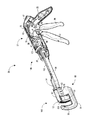
図1を図2から図5と組み合わせて参照すると、手術用ステープリングおよび切開器具が、より詳しく言うと、組織をステープリングし切開するように設計された手術用リニアステープラー20が示されている。手術用リニアステープラー20は第1の近位の端部のハンドル21と反対側の遠位の端部の端部エフェクター80とを有する。端部エフェクター80は本発明の好ましい実施の形態では湾曲している。右ハンド構造プレート34および左ハンド構造プレート35(「ハンドルプレート」とも呼ばれる。)は各々ハンドル21を手術用器具の端部エフェクター80に結合している(左ハンドルプレートは図1には示されていない)。ハンドル21は左ハンドシュラウド(左ハンドシュラウドは図1には示されていない。)に結合された右ハンドシュラウド22を有する。ハンドル21は手術用リニアステープラー20を把持し操縦するための本体部分23(図2から図5が参照される。)をも有する。
Referring to FIG. 1 in combination with FIGS. 2-5, a surgical stapling and dissecting instrument, more particularly, shows a surgical
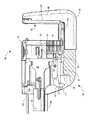
端部エフェクター80は、カートリッジモジュール120(図6から図9が参照される。)とU形の形状の支持構造81とを含んだ手術用の締結アセンブリからなる。閉鎖部材28の遠位の端部30がカートリッジモジュール120を受容するように配置されている。端部エフェクター80は前に発射されたカートリッジモジュール120を発射するのを防止するための安全固定機構180(図31に最も良く示されている。)をも含んでいる。カートリッジモジュール120はアンビル122に連結されたカートリッジハウジング121を収容している。カートリッジモジュール120は、保持ピン125、ナイフ126、取り外し可能なリテーナ160、および、ナイフ126の両側にひとつまたは複数の列(すなわち、ステープルライン)の互い違いの配列の複数のステープル収容溝128を現している組織接触面127をも含んでいる。ステープル(図示されていない。)はカートリッジハウジング121の組織接触面127と向かい合うアンビル122のステープル形成面129に向かってカートリッジハウジング121から発射される。
The
以下の開示に基づいて明らかになるように、本発明の手術用リニアステープラー20は交換可能なカートリッジモジュール120を備えた複数回発射する器具として設計されている。しかし、基礎をなす本発明のさまざまな発想は本発明の真髄を逸脱せずに一回だけ発射する器具にも等しく適用できることが理解されなければならない。
As will become apparent based on the following disclosure, the surgical
端部エフェクター80の支持構造81は、支持構造81から右ハンドルプレート34および左ハンドルプレート35の受容開口内に延在する肩部リベット82およびポスト83によって右ハンドルプレート34および左ハンドルプレート35に各々取り付けられている。本発明の好ましい実施の形態に基づけば、支持構造81は単一の部品構造で作られている。より詳しく言うと、支持構造81は例えばアルミを押出し成形し続いて本発明に基づいて開示された支持構造81に機械加工することによって形成される。このように支持構造81を構成することによって、複数の部品が必要とされず関連する製造および組み立てコストがかなり低減される。さらに、支持構造81が単一の構造であることが本発明の手術用リニアステープラー20の全体の安定性を増強することが確信される。さらに、単一の押出し成形された構造の支持構造81は重量を低減し、コバルトの放射が押出し成形されたアルミを効果的に貫通するので滅菌を容易にし、押出し成形によって得られた滑らかな外側表面に基づいて組織への外傷が減らされる。
The
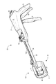
手術用リニアステープラー20のハンドル21は、外科医が自分の手のひらでつかむハンドグリップ24を含んでいる(図2から図5が参照される)。ハンドグリップ24は右ハンドシュラウドハンドル25(図1が参照される。)と左ハンドシュラウドハンドル(左ハンドシュラウドハンドルは図1に示されていない。)とからなる。回動するようにハンドル21の下側から延出しているのは閉鎖トリガー26および発射トリガー27である。図1に示されている手術用リニアステープラー20は、閉鎖トリガー26および発射トリガー27が駆動されていない位置にあり、カートリッジモジュール120が挿入され、リテーナ160が取り除かれた状態で図示されている。その結果、カートリッジハウジング121は組織をカートリッジハウジング121およびアンビル122の間に配置するためにアンビル122から離れている。
The
手術用リニアステープラー20のハンドル21は組織保持ピン駆動機構100を含んでいる。組織保持ピン駆動機構100はハンドル21の上部面に配置されたサドル形のスライド101を含んでいる。スライド101を手動で動かすことによって押出しロッド102が遠位の向きに動く。押出しロッド102はカートリッジモジュール120の保持ピン125に結合されている。押出しロッド102が遠位の向きに動いたり近位の向きに後退したりすると、保持ピン125がそれに対応して動く。保持ピン駆動機構100は、閉鎖トリガー26が閉鎖トリガー26の最も近位の位置に既に配置されていない場合に閉鎖トリガー26を駆動したときに保持ピン125が自動的に遠位の向きに動くようにハンドル21内の閉鎖トリガー26にも解除可能に結合されている。
The
図2から図5を簡単に参照すると、カートリッジモジュール120が装填されて、手術用リニアステープラー20の端部エフェクター80を駆動するために閉鎖トリガー26および発射トリガー27が順番にハンドグリップ24に向けて引かれたときに起こる事柄を示している。手術用リニアステープラー20には図2に示されているようにカートリッジモジュール120が装填され、次にリテーナ160が取り外される。手術用リニアステープラー20はこうして図1に示されているように組織を受容する準備が整う。
Referring briefly to FIGS. 2-5, the
閉鎖トリガー26が部分的に引かれて図3に示すようにその第1の移動止め位置に配置されると、カートリッジハウジング121は以下により詳しく記載されるようにその完全に開いた位置から開いた位置と閉じた位置との間の中間の位置へ移動する。同時に、組織保持ピン駆動機構100は保持ピン125をカートリッジハウジング121からアンビル122の開口を通すように前方に向けて動かす。この位置では、カートリッジハウジング121とアンビル122との間に配置されている組織は適正に位置決めされて、組織がカートリッジハウジング121とアンビル122との間で確実に保持される。したがって、閉鎖トリガー26がその中間の位置への駆動を完了すると、カートリッジハウジング121およびアンビル122はそれに対応して組織を保持するそれぞれの位置に配置されている。
When the
閉鎖トリガー26が図4に示されているようにハンドグリップ24の前方端部に隣接するように完全に引かれると、カートリッジハウジング121の組織接触面127およびアンビル122のステープル形成面129は互いに近づき、適正に位置決めされ保持された組織は結果的に完全に締めつけられる。さらに、発射トリガー27がハンドグリップ24に向けて反時計回りに回動して外科医がステープルを発射するために発射トリガー27を握ることができるようになっている。したがって、発射トリガー27はこのとき外科医が発射トリガー27を引いて組織をステープリングし切開するための位置に配置されている。発射トリガー27が図5に示すようにステープルを発射するために完全に引かれると、発射トリガー27は閉鎖トリガー26にほぼ接近して留まる。
When the
図6から図9を参照して、カートリッジモジュール120がより詳細に説明される。本発明のカートリッジモジュール120はステープリング機能および切開機能が手術用器具を駆動する間に同じ向きで働く手術用リニアステープラー20で用いるための切開および密封機構を提供する。本発明のカートリッジモジュール120は手術用リニアステープリング器具と共に用いるように特定して適合されているが、本発明のカートリッジモジュール120の発想は本発明の真髄を逸脱することなく別の手術用器具にも適用できる。より詳しく言うと、本発明のカートリッジモジュール120はナイフ126が切開過程の間に対応するワッシャ123と共に用いられるようにしている。本発明のカートリッジモジュール120は手術用リニアステープラー20を複数回発射することが切開機能を制約しないことを確実にする。これは、アンビル122を、とりわけ切開ワッシャ123をカートリッジモジュール120に組み合わせることによって達成される。ワッシャ123をカートリッジモジュール120に組み合わせることによって、新たなワッシャ123がカートリッジモジュール120が交換される度に提供され、その結果切開性能が改善される。
The
より詳しく言うと、カートリッジモジュール120はステープル収容スロット128内に配置された複数のステープル(図示されていない。)を収容するカートリッジハウジング121を含んでいる。ステープルの直ぐ後ろには、ステープルをステープル収容スロット128の外に押出すために配置されたドライバー131が配置されている。ナイフホルダー130がカートリッジハウジング121内のドライバー131のすぐ近位の側に配置されている。ナイフホルダー130は、その機能が以下により詳しく説明されるナイフリトラクターフック45(図37が参照される。)と相互に作用するためのスロット172およびリッジ173を含んでいる。ナイフホルダー130は、ナイフホルダー130からドライバー131のスロット200およびカートリッジハウジング121のスロット199を通って遠位の向きに延出するナイフ126に取り付けられている。
More specifically, the
より詳しく言うと、そして図41および図42を参照して、本発明の好ましい実施の形態に基づくナイフ構造は2つのコンポーネントから構成されている。ナイフ構造は金属製のブレードすなわちナイフ126およびプラスチック製のナイフホルダー130を含んでいる。ナイフホルダー130はナイフ126の近位の端部(そして切開エッジとは反対側)に配置されている。手術用リニアステープラー20の内側の発射バー43の端部にはナイフリトラクターフック45が配置されている。ナイフトラクターフック45は、カートリッジモジュール120が手術用リニアステープラー20の端部エフェクター80に装填されたときにナイフホルダー130のスロット172を受容するための上向きのフックを含んでいる。
More specifically, and with reference to FIGS. 41 and 42, the knife structure according to the preferred embodiment of the present invention is comprised of two components. The knife structure includes a metal blade or
カートリッジモジュール120が手術用リニアステープラー20の端部エフェクター80に装填されたとき、ナイフリトラクターフック45はナイフホルダー130のスロット172に滑り込む。カートリッジモジュール120が手術用リニアステープラー20の端部エフェクター80に完全に装着されると、ナイフリトラクターフック45およびナイフホルダー45は軸方向で係合してナイフ126が発射バー43が後退したときに発射バー4と共に動くようになっている。ナイフ126の装填されたカートリッジモジュール120内での位置は、遠位の側はドライバー131の移動止めポスト140によって決定され、近位の側はナイフホルダー130の最も後方の移動止め突起部139によって決定される。発射の後、発射バー43はナイフ126をカートリッジモジュール120内に引き戻してナイフ126を後退した位置に保持する移動止め突起部139と係合する。これによってナイフ126が前方へ動くことおよび取り外しおよび廃棄の間にカートリッジモジュール120から出ることが防止される。
When the
本発明のナイフ構造はとても有益である。本発明のナイフ構造はカートリッジモジュール120から突出する特徴部をまったく有しない。スロット172は、偶然に接触してナイフ126が意図せずに前進するようにするかもしれないカートリッジモジュール120からの突起部を確実に無くしている。さらにナイフ126は発射バー43に直接取り付けられている。ナイフ126を発射バー43に直接取り付けることによってナイフ126およびナイフホルダー130を発射バー43と共に直接後退させることができる。さらに、ナイフホルダー130に移動止め突起部139を設けることによってナイフホルダー230とカートリッジハウジング121のスロット137との相互作用が発射後にナイフ126を後退した位置に保持するように働く。
The knife structure of the present invention is very beneficial. The knife structure of the present invention does not have any features that protrude from the
上述したように、ナイフホルダー130はカートリッジハウジング121のスロット137を通って延在する移動止めポスト138を有する。ナイフホルダー130の移動止めポスト138は、ナイフ126およびナイフホルダー130が長手方向に動く間カートリッジハウジング121のスロット137の移動止め突起部139と接触するように配置されている。同様に、ドライバー131は、カートリッジハウジング121のスロット137の近位の移動止め突起部141および遠位の移動止め突起部142に接触するように配置された移動止めポスト140を有する。
As described above, the
ナイフ126およびスロット199、スロット200は、少なくとも一列のステープルがナイフ126の両側の各々に配置されるように位置決めされている。本発明の好ましい実施の形態に基づけば、二列のステープルのスロット128(および二列のステープル)がカートリッジハウジング121のスロット199の両側の各々に設けられている。
カートリッジハウジング121はナイフスロット199の両端の各々に配置された2つのほぼ円形の開口143および開口144を含んでいる。カートリッジハウジング121の基部に設けられたほぼ円形の開口143はガイドピン124をカートリッジハウジング121に通す形状および寸法を有する。カートリッジハウジング121の上部のほぼ円形の開口144は保持ピン125をカートリッジハウジング121に通す形状および寸法を有する。ステープルスロット128はステープルがほぼ円形の開口143および開口144を越えて横方向に延在するように配列されている。
本発明の好ましい実施の形態に基づけば、アンビル122はプラスチック製のワッシャ123および金属製のステープル形成面129を含んでいる。アンビル122はステープル形成面129を整合した構成に保つために配置されている。保持ピン125は保持ピン125の円周スロット135およびカプラー133の溝134によってカプラー133に結合されている(図14に最も良く示されている)。カプラー133はカートリッジハウジング121のアーム145内に配置されていて端部キャップ146によってアーム145内に保持されている。
In accordance with a preferred embodiment of the present invention, the
ガイドピン124および保持ピン125は、ナイフ126の端部126aおよび端部126bが配置される対応するスロット147aおよびスロット147bを含んでいる(図8、図9、図36、図39、および図40に最も良く示されている)。ガイドピン124の近位の端部148はアンビル122の近位の端部149に結合されている。ガイドピン124の遠位の端部150はカートリッジハウジング121から延出しアンビル122のスロット151を通って延在している。切開ワッシャ123はワッシャ123の舌部153の下に嵌め合わされるアンビル122の溝152によってアンビル122に嵌め込まれる。切開ワッシャ123の反対側の端部154はアンビルアーム155の下に嵌め込まれピン156によってアンビルアーム155にピン留めされる。この位置では、ワッシャ123の切開面157はアンビル122のスロット151を通って延出している。切開ワッシャ123をアンビル122に組み付けることによってガイドピン124がアンビル122のスロット151および切開面157によって形成された開口内に捕獲され、したがって、アンビル122がカートリッジハウジング121に機能的に結合される。リテーナ160は図7に示されているようにカートリッジモジュール120に取り付けられていて端部エフェクター80が挿入されるまでカートリッジモジュール120のコンポーネントを望ましい配置に保持する。
図25から図29と組み合わせて図6から図12を再び参照して、リテーナ160がより詳しく説明される。リテーナ160はカートリッジハウジング121の突起部159の周りに配置される溝161を有する。リテーナ160はリテーナ160内で往復運動するために配置された弾性の内側ばねアーム162を収容している。リテーナ160はガイドピン124の周りに部分的に延在する収容スロット163を含んでいる。ばねアーム162は、ガイドピン124の周りに部分的に延在し収容スロット163と逆の向きを向くように構成された収容スロット164を含んでいる。リテーナ160は、収容スロット163および収容スロット164がガイドピン124を取り囲んでリテーナ160をカートリッジモジュール120に閉じ込めるようにカートリッジモジュール120に配置される。ばねアーム162はリテーナ160からアンビルアーム155の下へ下向きに延在する解除タブ165を含んでいる。したがって、リテーナ160はカートリッジモジュール120が端部エフェクター80内に適正に配置されるまでカートリッジモジュール120から容易に取り外せない。カートリッジモジュール120が端部エフェクター80に適正に配置されると、解除タブ165が端部エフェクター80に係合してリテーナ160を解放する。
Referring again to FIGS. 6-12 in combination with FIGS. 25-29, the
図2および図13と組み合わせて再び図1を参照して、手術用リニアステープラー20のコンポーネントがより詳しく説明される。手術用リニアステープラー20は、ハンドル21から端部エフェクター80の手術用締結アセンブリ内に延在するほぼU形の断面形状を有する長寸の閉鎖部材28を含んでいる。本発明の好ましい実施の形態に基づけば、閉鎖部材28は本発明に基づく動きおよび機能を得るための形状を与えられた成形プラスチック部材である。閉鎖部材28をプラスチックで作ることによって、製造コストが低減され手術用リニアステープラー20の重量も低減される。さらに、手術用リニアステープラー20はプラスチックがステンレス鋼に比べてより透過しやすいのでコバルト放射を用いた滅菌がより容易である。別の実施の形態に基づけば、閉鎖部材28は仕上の特徴が機械加工によって形成された押出し成形されたアルミで作られていてよい。押出し成形されたアルミはプラスチック製のコンポーネントほどには製造が容易ではないかもしれないが、それでもなお同様の利点(すなわち、コンポーネントの削減、組み立ての容易さ、軽量化、滅菌の容易さ)を有している。
Referring again to FIG. 1 in combination with FIGS. 2 and 13, the components of the surgical
閉鎖部材28の遠位の部分は支持構造81の壁84を通過している。遠位の部分はカートリッジモジュール120のカートリッジハウジング121を受容して保持するように配置されている。閉鎖部材28の中心部分は右ハンドルプレート34および左ハンドルプレート35の各々の間に配置されている。右ハンド閉鎖リンク36および左ハンド閉鎖リンク37は、各々、第1の一体閉鎖リンクピン38によって閉鎖部材28の右近位の端部および左近位の端部に回動するように取り付けられている。閉鎖リンク36および閉鎖リンク37の反対の端部では、閉鎖リンク36および閉鎖リンク37が第2の一体閉鎖リンクピン39に回動可能に取り付けられている。第2の一体閉鎖リンクビン39は閉鎖リンク36および閉鎖リンク37をスロット付の閉鎖アームリンク40に結合している。スロット付の閉鎖アームリンク40は、閉鎖トリガーピボットピン41によって手術用リニアステープラー20の右ハンドルプレート34および左ハンドルプレート35に回動可能に取り付けられている。閉鎖トリガー26は閉鎖トリガーピボットピン41を中心にしてハンドグリップ24に向かってまたはハンドグリップから遠ざかるように回動するようにスロット付の閉鎖アームリンク40から下向きに延在している。ハンドル21のハンドグリップ24内に収容された閉鎖ばね42はスロット付の閉鎖アームリンク40に取り付けられていて外科医が閉鎖トリガー26をハンドグリップ24に向けて引いたときに望まれる抵抗力を提供し閉鎖トリガー26を開いた位置に向けて付勢する。
The distal portion of the
図13および図14を参照して、保持ピン駆動機構100のコンポーネントが説明される。ハンドル21は直線状の動きをするようにハンドル21の上部に取り付けられたサドル形のスライド101を含んでいる。スライド101は押出しロッドドライバー104から外向きに延在してハンドル21のスロット105(図2が参照される。)を通るポスト103に結合されている。押出しロッドドライバー104はスロット105によって手術用リニアステープラー20の長手方向の軸に沿った長手方向の動きを抑制されている。押出しロッドドライバー104は押出しロッドドライバー104のスロット108にスナップ嵌めされる押出しロッド102の周方向の溝107によって押出しロッド102に結合されている。押出しロッド102の遠位の端部はカートリッジモジュール120のカプラー133の近位の端部の溝132と相互に連結された周方向の溝109を含んでいる(図22に最も良く示されている)。カプラー133の遠位の端部は保持ピン125の周方向の溝135と相互に連結するための溝134を含んでいる。
The components of the holding
閉鎖部材28は閉鎖部材28の両側からハンドル21内に横方向に延出するポスト29を含んでいる。これらのポスト29はヨーク111のL形のスロット110と摺動可能に連結している。ヨーク111はヨーク111のピボットピン112によってハンドル21に回動可能に取り付けられている。ヨーク111は押出しロッドドライバー104のカム面114を押すように配置されたカムピン113を含んでいる。
The
図13および図37を参照して、発射伝達アセンブリのコンポーネントが説明される。発射伝達アセンブリは、ハンドル21から端部エフェクター80の手術用締結アセンブリ内に延在する長寸の発射バー43を含んでいる。発射バー43はU形の断面形状の閉鎖部材28内に配置されている。発射バー43の遠位の端部はカートリッジハウジング121内に延在していてナイフホルダー130およびドライバー131のすぐ近位の側に配置されている。発射バー43の遠位の端部はナイフリトラクターフック45を有するナイフリトラクター44に取り付けられている。
With reference to FIGS. 13 and 37, the components of the firing transmission assembly will be described. The firing transmission assembly includes a
発射バー43はハンドル21内に収容されている発射バー43の部分に長方形の受容スロット46を有する(図13が参照される)。第1の一体閉鎖リンクピン38は受容スロット46を通って延在している。発射バー43は近位の端部部分47をも有する。発射バー43の近位の端部部分47の下側には摺動面48が設けられている。近位の端部部分47は摺動面48から延出する終端側係合面49をも有する。発射トリガー27は閉鎖トリガーピボットピン41から離れた発射トリガーピボットピン50によってハンドルプレート34およびハンドルプレート35に回動可能に取り付けられていて閉鎖トリガーピボットピン41および発射トリガーピボットピン50が各々互いに独立した軸を中心にして回転するようになっている。発射トリガー27は発射トリガーピボットピン50の位置で発射トリガー27から発射バー43の近位の端部部分47の摺動面48に配置された先端52まで延在するアーチ形の発射トリガーリンク51を含んでいる。ハンドル21内では、発射トリガー27は第1の発射トリガーばねアーム53および第2の発射トリガーばねアーム54の各々に取り付けられている。第1の発射トリガーばねアーム53および第2の発射トリガーばねアーム54は発射トリガー43の右半分のねじりばね(図示さていない。)を支持している。最後に、発射バー戻りばね55は発射バー43のハンドル21内にある部分で発射バー43の下側に取り付けられていて発射バー43をその駆動されていない位置に向けて付勢している。
The firing
閉鎖トリガー26がハンドグリップ24に向けて引かれると、スロット付の閉鎖アームリンク40および閉鎖リンク36は発射バー43の受容スロット46内で遠位の向きに動く。この遠位の向きの動きによって、閉鎖部材28は対応して遠位の向きに動く。同様に、発射バー43は閉鎖部材28と同時に遠位の向きに動き、その理由は閉鎖リンク36および閉鎖リンク37が取り付けられた第1の一体閉鎖リンクピン38が発射バー43の受容スロット46を通って延在しているからである。
As the
中間の閉鎖移動止め位置を定義する機構および閉鎖トリガー26の駆動された位置からはじめの駆動されてない位置への解除が図13から図20と組み合わせて図1を参照して説明される。スロット付の閉鎖アームリンク40の上側には中間の移動止め57および閉鎖移動止め58を現すクランプ摺動面56が設けられている。解除蓋い59がクランプ摺動面56上を摺動し中間の移動止め57および閉鎖移動止め58に係合する。解除蓋い59はその遠位の端部に横方向に延在する蓋いラグ60(図1に最も良く示されている。)を有する。解除蓋い59はハンドル21内に配置されていて、ハンドル21の外側に配置されている解除ボタン61に一体的に取り付けられている。解除ボタン61は親指台62を有し、解除ボタン61は解除トラニオン63によってハンドル21に回動可能に取り付けられている。解除ボタン61はハンドル21から外向きに付勢されていて、したがって解除蓋い59はばね保持ピン65によってハンドル21に取り付けられかつボタンばねポスト66によって解除ボタン61に取り付けられた解除ばね64によってクランプ摺動面56に向けて下向きに付勢されている。スロット付の閉鎖アームリンク40は中間の移動止め57および閉鎖移動止め58の間に配置されたアーチ形の凹部67を有する。このアーチ形の凹部67に回転運動するために配置されているのは右ハンドトグル(右ハンドトグルは図示されていない。)に一体的に結合された左ハンドトグル68である。各トグル68は蓋いラグ60と係合可能なトグルアーム69を有する。蓋いラグ60は凹状の近位の表面70を有していてトグルアーム69と蓋いラグ60の間に隙間が設けられている。
The mechanism defining the intermediate detent position and the release of the
図31(カートリッジおよび支持構造の切欠き図)を参照して、発射された器具の固定機構180のコンポーネントが説明される。固定機構180はピン182によって閉鎖部材28の遠位の端部30に回動可能に取り付けられた固定レバー181を含んでいる。固定レバー181はばね(図示されていない。)によって支持構造81の基部に向けて下向きにばね付勢されている。固定レバー181は近位の端部184および遠位の端部185を含んでいる。近位の端部184はカム面186および固定溝187を有する。端部エフェクター80の支持構造81は固定機構180が働いているときに固定溝187と相互に作用するように配置されたリッジ85を含んでいる。支持構造81は壁84の間の基部面86を含んでいる。基部面86は固定レバー181が働いていないときにカム面186と相互に作用するように配置されている。
Referring to FIG. 31 (cutaway view of cartridge and support structure), the components of the fired
カートリッジモジュール120の装填、閉鎖機構、保持ピン機構、発射伝達機構、中間の移動止め57および閉鎖移動止め58、解除機構、および固定機構180の動作が以下に説明される。図7から図12および図21から図28を参照して、カートリッジモジュール120の組織端部エフェクター80への装填が説明される。カートリッジモジュール120は手術用リニアステープラー20の組織端部エフェクター80に対して選択的に着脱されるような形状および寸法を有する。
The operation of the
図7に示されているようにカートリッジモジュール120を手術用リニアステープラー20の端部エフェクター80に挿入する前に、リテーナ160は溝161がリテーナ160の上端部の突起部159の周りに配置されていて切り離しを防止しているのでカートリッジモジュール120から容易に取り除けない。さらに、リテーナの収容スロット163および収容スロット164は図25に示されているようにリテーナ160の底部でガイドピン124の周りに配置されていて切り離しを防止している。
Before inserting the
取り付けられたリテーナ160は、カートリッジモジュール120の構造を支持し、握るための広い表面積を提供し、この両方の特徴が装填を容易にしている。リテーナ160はさらに無頓着な取り扱いの間にステープルがカートリッジから移動するのを防止し無頓着な取り扱いの間にナイフ126が偶発的に露出されるのを防止する。
The attached
ナイフ126の動きおよびステープルの動きは一連の移動止めによって装填する前および装填する間にさらに抵抗を受ける。図9を参照すると、ナイフホルダー130の移動止めポスト138はカートリッジハウジングのスロット137の移動止め突起部139によって近位の向きおよび遠位の向きに動くのが防止されている。ドライバー131は移動止めポスト140とカートリッジハウジングのスロット137の移動止め突起部141との相互作用によってカートリッジモジュール120の無頓着な取り扱いよっておよびカートリッジモジュール120を手術用リニアステープラー20に装填する間に遠位の向きに動くのが防止されている。
カートリッジモジュール120は、カートリッジハウジング121が図21から図24に示されているように閉鎖部材28の遠位の端部30に滑り込むように組織端部エフェクター80に装填される。閉鎖部材28の壁31aおよび壁31bは装填の間にカートリッジハウジング121のスロット170aおよびスロット170bに滑り込む。同時に、タブ174(図8が参照される。)はU形の形状の支持構造81の溝88に滑り込む。より詳しく言うと、タブはU形の形状を有し支持構造81に沿って溝88に嵌め合わされてカートリッジモジュール120を端部エフェクター80にしっかりとかつ正確に結合する。カートリッジモジュール120の装填は移動止め171が図21から図24に示されているように閉鎖部材の遠位の端部30の移動止め溝32にスナップ嵌めされたときに完了する。
The
図24に示された位置では、カートリッジモジュール120は完全に装填されていてカプラー133の近位の溝132は押し出しロッド102の遠位の周方向の溝109に係合していてカートリッジモジュール120の保持ピン125は保持ピン前進機構100に結合されている。ナイフホルダー131のスロット172は装填の間にナイフリトラクションフック45に係合していてフック45がカートリッジモジュール120の装填が完了したときにナイフホルダー130のリトラクションリッジ173に係合しているようになっている。
In the position shown in FIG. 24, the
カートリッジモジュール120の装填が完了したとき、ドライバー131に配置されているポスト188は固定レバー181の遠位の端部185に接触する(図31が参照される)。ポスト188の接触によって固定レバー181が固定レバーピン182を中心にしてカム面186がU形の形状の支持構造81の基部面86と水平方向で整合する位置まで回動する。
When the loading of the
リテーナ160はこのとき端部エフェクター80から取り外せるようになる。より詳しく言うと、カートリッジモジュール120の装填が完了すると、解除タブ165が支持構造162に接触し(図23が参照される。)、その結果カートリッジモジュール120が図24に示されているように完全に装填されたときばねアーム162が上向きに動く。この上向きの動きによって、収容スロット164が上に変位してガイドピン124がもはや収容されなくなる(図25および図26が参照される)。図27から図29を参照すると、親指パッド166に加えられた除去力が溝161が突起部159からはずれるようになるまでリテーナ160を突起部159を中心にして回動させる。リテーナ160を除去することによって装填された手術用リニアステープラー20が使用できるようになる。
At this time, the
図15では、閉鎖トリガー26は図1および図13に示された開いたすなわち駆動されていない位置から部分的に引かれている。閉鎖トリガー26が部分的に引かれると、閉鎖トリガー26は閉鎖トリガーピボットピン41を中心にして反時計回りにハンドグリップ24に向けて回動する。閉鎖トリガー24が回動すると、スロット付の閉鎖アームリンク40および閉鎖プレート閉鎖リンク36および閉鎖プレート閉鎖リンク37は前方に動き、その結果閉鎖部材28および発射バー43が遠位の向きに動く。スロット付の閉鎖アームリンク40が前方に動くと、解除蓋い59の蓋いラグ60はクランプ摺動面56上を摺動する。蓋いラグ60はトグル68のトグルアーム69の遠位の端部に係合し、その結果トグル68を時計回りに回動させる。スロット付のアーム閉鎖リンク40が閉鎖トリガー26のハンドピース24に向かって回動するのに対応して前方へ動き続けると、解除蓋い59の蓋いラグ60は実質的に中間の移動止め57内に配置されるようになる。いったん中間の移動止め57に配置されると、閉鎖ばね42は閉鎖トリガー26をそのはじめの駆動されていない位置に戻すことができない。閉鎖トリガー26はこうしてその中間の部分的に閉じた位置に配置されて図15に示すように組織をカートリッジハウジング121とアンビル122の間で適正に配置して保持する。さらに、閉鎖部材121および発射バー43が遠位の向きに動くと、アーチ形の発射トリガーリンク51の先端52は発射バー43の近位の端部部分47の摺動面48上を摺動する。
In FIG. 15, the
開いた位置から中間の位置への閉鎖ストロークの間に保持ピン機構100が駆動される。閉鎖部材28の前方への動きは一体ポスト29を遠位の向きに動かす。ポスト29はヨーク111のL形の形状のスロット110に接触する。こうして、ポスト29が遠位の向きに動いてL形の形状のスロット110に当接してヨーク111をピン112を中心にして回動させる。その回動によってヨーク111のベアリングポスト113が押し出しロッドドライバー104のカム面114に接触するようになる。ヨーク111をさらに回動させることによってベアリングポスト113はカム面114と接触しながら押し出しロッドドライバー104を遠位の向きに動かす。押し出しロッドドライバー104は押し出しロッド102と接触し、押し出しロッド102を遠位の向きに動かす。次に、押し出しロッド102はカプラー133および保持ピン125を遠位の向きに動かす。中間の移動止め57の位置への閉鎖ストロークが完了することによって、保持ピン125はカートリッジハウジング121の開口144、アンビル155のスロット、ワッシャ170の開口を通って支持構造81の開口89(図示されていない。)内まで遠位の向きに動く。カートリッジハウジング121の接触面127およびアンビル122の間に配置された組織はこのとき保持ピン125とガイドピン124の間に捕獲されている。
The holding
同様の結果がサドルスライド101を手動で遠位の向きに動かすことによって閉鎖する前に得られる。サドルスライド101の摺動によって、押し出しロッド102、カプラー133、および保持ピン125が保持ピン125がアンビル122、ワッシャ123、および支持構造81の開口89を通って完全に配置されるまで前方に動く。保持ピン125が手動で前方に動かされた後の閉鎖ストロークも上述したようにヨーク111を回動させるが保持ピン駆動機構100はそれ以外の別の動作はしない。
Similar results are obtained prior to closing by manually moving the
開いた位置から中間の移動止め57の位置への閉鎖ストロークは、固定レバー181が図31(開いた位置)および図32(中間の位置)に示されているようにピン182によって閉鎖部材28に取り付けられているので固定レバー181を遠位の向きに動かす。固定レバー181の遠位の向きの動きによって、カム面186が支持構造81の固定リッジ85に接触し、その結果固定レバー181が時計回りに回動して支持構造81の基部面86と摺動可能に接触する。この位置では、固定レバー181の遠位の端部185は回動してドライバー131のポスト188から離れている。
The closing stroke from the open position to the
図16を特に参照すると、閉鎖トリガー26が中間の移動止め57の位置からハンドグリップ24に向けて引かれたとき、トグル68のトグルアーム69は蓋いラグ60から外れる。その結果、トグル68は時計回りの回動を続け、解除覆いラグ60はトグルアーム69に乗り上げ閉鎖トリガー26がさらに動き続けるにしたがって閉鎖移動止め58内に落ちる。解除覆い59はトグルアーム69に乗り上げると解除覆い59は解除ボタン61をピボット63を中心にして回動させる。解除覆い60が閉鎖移動止め58に落下すると、解除覆い60は外科医に閉鎖位置に到達したことを警報する可聴のクリック音を鳴らす。
With particular reference to FIG. 16, the
さらに、発射バー43が前方に動き続けると、アーチ形の発射トリガーリンク51の先端52は発射バー43の近位の端部部分47の摺動係合面49に接触するようになる。その結果、発射トリガー27は発射バー43を組織が十分に締めつけられた後にステープラーを発射するために遠位の向きに動かし続けることができる。アーチ形の発射トリガーリンク51の先端52は近位の端部部分47の係合面49と係合するようになったとき、発射トリガー27は発射トリガー27の右ハンド側のねじりばねの動きに対応してハンドグリップ24に向けて反時計回りに回動し始める(ねじりばねは図示されていない)。発射トリガー27は閉鎖トリガー26の回動運動に無関係に回動するが、発射トリガー27の回動は発射バー43が発射トリガーリンク51を発射バー43の端部係合面と係合させるように遠位の向き移動するまで阻止されている。
Furthermore, as the firing
特に図17を再び参照すると、閉鎖トリガー47が十分に引かれてハンドグリップ24に隣接して配置されたとき、解除蓋い59の遠位の端部の蓋いラグ60は閉鎖移動止め58に配置される。閉鎖移動止め58の位置では、組織はカートリッジハウジング121とアンビル122の間で十分に締めつけられ、閉鎖ばね42は閉鎖トリガー26をその初めの位置に戻すことができない。したがって、閉鎖トリガー26は図4に示された位置に保持される。
With particular reference again to FIG. 17, when the
閉鎖トリガー26が反時計回りに動くのと同時に、発射トリガー27はねじり発射バー戻りばね55の働きによって発射トリガー27が手術用リニアステープラー20のハンドル21に対して比較的垂直に配置されるまで反時計回りに回動を続ける。十分に締めつけられた位置で、アーチ形の発射トリガーリンク51の先端52は発射バー43の近位の端部部分47の係合面に十分係合し、したがって、発射トリガー27はステープラーを組織内に発射するために発射バー43を遠位の向きにさらに動かす位置にある。
At the same time as the
完全に閉じた位置では、カートリッジハウジング121のステープルポケット128は図33に示されているようにアンビル122のステープル形成面129と整合している。保持ピン125はアンビル122およびカートリッジハウジング121の上部と整合し、ガイドピン124はカートリッジハウジング121の底部およびアンビル12の底部と整合している。
In the fully closed position, the
図18および図34に示されているように、発射トリガー27は閉鎖トリガー26に隣接して配置されるまでハンドグリップ24に向けて回動するように引かれる。発射トリガー27が回動する間に、発射バー43は遠位の向きに動いてナイフホルダー130に接触する。その結果ナイフホルダー130が遠位の向きに動いてナイフ126およびドライバー131と接触する。ドライバー131の遠位の向きの動きは、ステープル(図示されていない。)をアンビル122のステープル形成面129内に向けて遠位の向きに進め、その結果ステープルにほぼB形の形状を与える。ナイフ126はステープルに形が与えられるのと同時にガイドピン124および保持ピン125のスロット147内を遠位の向きに進む。これらのスロット147はナイフ126を切開ワッシャ123の切開面157に沿って案内し、その結果切開面157とナイフ126の間に捕獲された全ての組織を横に切開する。
As shown in FIGS. 18 and 34, the firing
発射トリガー27へ加えられている手の圧力を解除することによって、発射バー戻りばね55は発射バー43を後退させ発射トリガー27を図17に示された位置へ戻す。この動きによってリトラクターフック45がナイフホルダー130のリトラクションリッジ173およびナイフ126まで後退する。その結果としての近位の動きがナイフ126を図35に示されているようにカートリッジハウジング121内に後退させる。ナイフホルダー130の移動止めポスト138は後退してカートリッジハウジング121の移動止め139と係合しナイフホルダー130およびナイフ126をこの後退した位置に保持する。ドライバー131はドライバー131の移動止めポスト140がカートリッジスロット137の移動止め142と係合することによってその最も遠位の(発射された)位置に保持される。
By releasing the hand pressure being applied to the firing
使用者が誤って別の手術用器具を切りつけるなどによってナイフ126への妨害が生じて発射バー戻りばね55からの力が発射バー43を後退させるしたがってナイフ126をカートリッジハウジング121内へ後退させるのに十分でない場合には、使用者は発射バー27を時計回りに回動させて切開システムを手動で後退させることができる。手動での時計回りの動きによってアーチ形の発射トリガーリンク51は発射バー43の近位の端部47の発射バーリトラクションタブ71に衝突するまで時計回りに回動する。時計回りに回動するアーチ形の発射トリガーリンク51と発射バーリトラクションタブ71との接触によって発射バー43は近位の向きに後退して図17に示されている位置に戻る。次にこれによってリトラクターフック45がナイフホルダー130のリトラクションリッジ173およびナイフ126まで後退する。したがって、この安全機構によって使用者は切開機構を安全な位置まで後退させ発射システムを手術用リニアステープラー20が以下に説明されるように開かれるようにする位置に戻すことができる。
The force on the firing
図19を参照して、外科医が解除ボタン61を押したときに解除覆い59が解除トラニオン63を中心にして時計回りに回動して蓋いラグ60を閉鎖移動止め63の位置から移動させる。蓋いラグ60は閉鎖移動止め63の位置から移動したときにトグルアーム69に載ってクランプリング40の中間の移動止め57の位置を迂回する。このようにして、閉鎖トリガー26および発射トリガー27は閉鎖ばね42および発射バーもどりばね55によって生み出された付勢力に応答してその初めの駆動されていない位置に戻ることができる。蓋いラグ60がトグル68のトグルアーム69に載っていると、トグルアーム69は閉鎖トリガー26および発射トリガー27が時計回りに回動してその初めの駆動されていない位置に戻る間に反時計回りに回動する。したがって、外科医は閉鎖トリガー26および発射トリガー27を解放して中間の移動止め57の位置に戻すことなく図20に示された位置に閉鎖トリガー26および発射トリガー27を戻すことができる。
Referring to FIG. 19, when the surgeon presses
手術用リニアステープラー20を図20に示された開いた位置へ解放することによって閉鎖部材28および取り付けられた固定レバー181は図36に示された完全に開いた位置へ後退する。この位置では、ドライバー131のポスト188はもはや固定レバー181の遠位の端部185を下に押さえつけるように配置されていない。ドライバー131は上述したようにポスト140およびカートリッジ移動止め142によって前方位置の所定の位置に移動止めされている。したがって、その近位の端部184が支持アーム面142に沿って摺動する固定レバー181は完全に後退したときに反時計回りに自由に回動できU形の形状の支持構造81の脚部85の下に固定溝181を落とせるようになる。固定レバー181はカートリッジモジュール120が図37に示されているように取り除かれたときにもこの位置に留まることになる。
By releasing the surgical
発射された後の手術用リニアステープラー20を閉じるためのどのような特徴部が、すでに発射された手術用器具の使用者にフィードバックを供給するように図38に示されているように固定溝187をリッジ85にひっかけるために試みられてもよい。この同じ特徴部がリテーナ160が装填の前に取り除かれた場合およびカートリッジモジュール120が適正な位置に配置されずに誤って装填された場合に働いてもよい。この場合、駆動ポスト188は固定ピン181を上述したように表面86に当接する位置に動かすための適正な位置に配置されていないこともある。同様に、既に発射されたカートリッジモジュール120は固定機構180を解放しないこともある。リッジ85に固定溝187がひっかかる前に固定機構180で閉鎖ストロークの移動を行えるようになっていることに気づくことが重要である。この閉鎖ストロークの移動は、固定機構180が移動していない場合に反作用として生ずる故障を原因として手術用器具が動かなくなっているのではないことを使用者に示している。したがって、使用者は固定機構が働いている場合には手術用器具が動かなくなってはいないが不適切に装填されていることを知ることができる。
Any feature for closing the surgical
手術用器具を図1および図2に示されている開いた位置に戻した後に、保持ピン機構100はサドル101を近位の向きに引いて手動で後退させられなければならない。この後退によって保持ピン125はカートリッジ121内に後退して戻る。手動での後退が完了すると、発射されたカートリッジモジュール120は取り外されて新しいカートリッジモジュール120と交換される。
After returning the surgical instrument to the open position shown in FIGS. 1 and 2, the retaining
好ましい実施の形態が図示され説明されたが、本発明をそのような開示に限定することは意図されておらず、むしろ本発明の真髄および範囲に包含される全ての変更および変形の構造が含まれることが意図されていることが理解される。 While preferred embodiments have been illustrated and described, it is not intended to limit the invention to such disclosure, but rather includes all modifications and variations of construction that fall within the spirit and scope of the invention. It is understood that it is intended.
この発明の具体的な実施態様は以下の通りである。
(1)体の組織に複数の手術用締結具を適用するように適合された手術用器具であって、
近位の端部および遠位の端部を備え、上記近位の端部にはハンドルが配置され、上記遠位の端部には端部エフェクターが配置されていて、上記端部エフェクターはカートリッジハウジングおよびアンビルを支持するような形状および寸法を有し、上記カートリッジハウジングおよび上記アンビルは互いに離れた第1の位置および互いに近づいた第2の位置の間を相対的に移動可能で、上記カートリッジハウジングが上記カートリッジハウジングと上記アンビルとの間を移動して組織を切開するように適合されたナイフ構造を含む、フレームと、
選択的に駆動するために上記端部エフェクターおよび上記カートリッジハウジングに関連した発射機構と
を有し、
上記ナイフ構造がナイフおよびナイフホルダーを含み、上記ナイフホルダーが上記ナイフの切開エッジとは反対側の上記ナイフの近位の端部に配置されていて、
上記発射機構がナイフリトラクターフックを含み、上記ナイフリトラクターフックの端部が上記カートリッジハウジングが上記手術用器具の上記端部エフェクターに装填されたときに上記ナイフホルダーを受容するための上向きのフックを含む、手術用器具。
(2)ナイフが金属からなる、上記実施態様(1)記載の手術用器具。
(3)ナイフホルダーがプラスチックからなる、上記実施態様(1)記載の手術用器具。
(4)カートリッジハウジングが手術用器具の端部エフェクターに装填されたときナイフリトラクターフックがナイフホルダーのスロットに滑り込む、上記実施態様(1)記載の手術用器具。
(5)発射の後に発射機構のナイフリトラクターフックがナイフをカートリッジハウジング内に引き戻して上記ナイフを後退した位置に保持する移動止めと係合する、上記実施態様(4)記載の手術用器具。
Specific embodiments of the present invention are as follows.
(1) a surgical instrument adapted to apply a plurality of surgical fasteners to body tissue,
A proximal end and a distal end, a handle disposed at the proximal end, and an end effector disposed at the distal end, the end effector being a cartridge The cartridge housing and the anvil have a shape and dimensions to support the housing and the anvil, the cartridge housing and the anvil being relatively movable between a first position apart from each other and a second position close to each other, the cartridge housing A frame comprising a knife structure adapted to move between the cartridge housing and the anvil to incise tissue;
A firing mechanism associated with the end effector and the cartridge housing for selective driving;
The knife structure includes a knife and a knife holder, the knife holder being disposed at a proximal end of the knife opposite the cutting edge of the knife;
The firing mechanism includes a knife retractor hook, the end of the knife retractor hook being an upward hook for receiving the knife holder when the cartridge housing is loaded into the end effector of the surgical instrument Surgical instruments, including
(2) The surgical instrument according to the embodiment (1), wherein the knife is made of metal.
(3) The surgical instrument according to the embodiment (1), wherein the knife holder is made of plastic.
(4) The surgical instrument according to embodiment (1), wherein the knife retractor hook slides into the slot of the knife holder when the cartridge housing is loaded into the end effector of the surgical instrument.
(5) The surgical instrument of embodiment (4), wherein after firing, the knife retractor hook of the firing mechanism engages a detent that pulls the knife back into the cartridge housing and holds the knife in the retracted position.
10 ステープルライン
12 組織保持特徴部
20 手術用器具
21 ハンドル
22 右ハンドシュラウド
23 本体部分
24 ハンドグリップ
26 閉鎖トリガー
27 発射トリガー
28 閉鎖部材
29 ポスト
30 遠位の端部
31a 壁
31b 壁
32 移動止め溝
34 右ハンド構造プレート
35 左ハンド構造プレート
36 右ハンド閉鎖リンク
37 左ハンド閉鎖リンク
38 第1の一体閉鎖リンクピン
39 第2の一体閉鎖リンクピン
40 閉鎖アームリンク
41 閉鎖トリガーピボットピン
42 閉鎖ばね
43 発射バー
44 ナイフリトラクター
45 ナイフリトラクターフック
46 受容スロット
47 近位の端部部分
48 摺動面
49 終端側係合面
50 発射トリガーピボットピン
51 発射トリガーリンク
52 先端
53 第1の発射トリガーばねアーム
54 第2の発射トリガーばねアーム
55 発射バー戻りばね
56 クランプ摺動面
57 中間の移動止め
58 閉鎖移動止め
59 解除蓋い
60 蓋いラグ
61 解除ボタン
62 親指台
63 解除トラニオン
64 解除ばね
65 ばね保持ピン
66 ボタンばねポスト
67 凹部
68 左ハンドトグル
69 トグルアーム
70 近位の表面
71 発射バーリトラクションタブ
80 端部エフェクター
81 支持構造
82 アンビル支持部(肩部リベット)
83 ポスト
84 壁
85 リッジ
86 基部面
88 溝
89 開口
100 組織保持ピン駆動機構
101 スライド
102 押出しロッド
103 ポスト
104 押出しロッドドライバー
105 スロット
107 溝
108 スロット
109 溝
110 スロット
111 ヨーク
112 ピボットピン
113 カムピン
114 カム面
120 カートリッジモジュール
121 カートリッジハウジング
122 アンビル
123 ワッシャ
124 ガイドピン
125 保持ピン
126 ナイフ
126a 端部
126b 端部
127 組織接触面
128 ステープル収容スロット
129 ステープル形成面
130 ナイフホルダー
131 ドライバー
132 溝
133 カプラー
134 溝
135 円周スロット
137 スロット
138 移動止めポスト
139 移動止め突起部
140 移動止めポスト
141 近位の移動止め突起部
142 遠位の移動止め突起部
143 開口
144 開口
145 アーム
146 端部キャップ
147a スロット
147b スロット
148 近位の端部
149 近位の端部
150 遠位の端部
151 スロット
152 溝
153 舌部
154 端部
155 アンビルアーム
157 切開面
159 突起部
160 リテーナ
161 溝
162 内側ばねアーム
163 収容スロット
164 収容スロット
165 解除タブ
166 親指パッド
167 第1のフィンガー部
168 第2のフィンガー部
170 ワッシャ
170a スロット
170b スロット
171 移動止め
171a スロット
171b スロット
172 スロット
173 リトラクションリッジ
174 タブ
180 安全固定機構
181 固定レバー
182 ピン
184 近位の端部
185 遠位の端部
186 カム面
187 固定溝
188 ポスト
199 スロット
200 スロット
10 Staple line 12
83 Post 84
Claims (4)
近位の端部および遠位の端部を備え、上記近位の端部にはハンドルが配置され、上記遠位の端部には端部エフェクターが配置されていて、上記端部エフェクターはカートリッジハウジングおよびアンビルを支持するような形状および寸法を有し、上記カートリッジハウジングおよび上記アンビルは互いに離れた第1の位置および互いに近づいた第2の位置の間を相対的に移動可能で、上記カートリッジハウジングが上記カートリッジハウジングと上記アンビルとの間を移動して組織を切開するように適合されたナイフ構造を含む、フレームと、
選択的に駆動するために上記端部エフェクターおよび上記カートリッジハウジングに関連した発射機構と
を有し、
上記ナイフ構造がナイフおよびナイフホルダーを含み、上記ナイフホルダーが上記ナイフの切開エッジとは反対側の上記ナイフの近位の端部に配置されていて、
上記発射機構がナイフリトラクターフックを含み、上記ナイフリトラクターフックの端部が上記カートリッジハウジングが上記手術用器具の上記端部エフェクターに装填されたときに上記ナイフホルダーを受容するためのフックを含み、
発射の後に上記発射機構が後退することで、上記発射機構の上記ナイフリトラクターフックが上記ナイフを上記カートリッジハウジング内に引き戻し、上記カートリッジハウジングは、上記ナイフが引き戻された状態で上記ナイフホルダーと係合して上記ナイフが上記カートリッジハウジングに対して前進することを防止する移動止めを有する、手術用器具。 A surgical instrument adapted to apply a plurality of surgical fasteners to body tissue,
A proximal end and a distal end, a handle disposed at the proximal end, and an end effector disposed at the distal end, the end effector being a cartridge The cartridge housing and the anvil have a shape and dimensions to support the housing and the anvil, the cartridge housing and the anvil being relatively movable between a first position apart from each other and a second position close to each other, the cartridge housing A frame comprising a knife structure adapted to move between the cartridge housing and the anvil to incise tissue;
A firing mechanism associated with the end effector and the cartridge housing for selective driving;
The knife structure includes a knife and a knife holder, the knife holder being disposed at a proximal end of the knife opposite the cutting edge of the knife;
The firing mechanism includes a knife retractor hook, and an end of the knife retractor hook includes a hook for receiving the knife holder when the cartridge housing is loaded into the end effector of the surgical instrument. ,
The firing mechanism retracts after firing, so that the knife retractor hook of the firing mechanism pulls the knife back into the cartridge housing, and the cartridge housing engages with the knife holder in a state where the knife is pulled back. A surgical instrument having a detent that prevents the knife from advancing relative to the cartridge housing.
Applications Claiming Priority (2)
| Application Number | Priority Date | Filing Date | Title |
|---|---|---|---|
| US53289703P | 2003-12-30 | 2003-12-30 | |
| US532897 | 2003-12-30 |
Publications (2)
| Publication Number | Publication Date |
|---|---|
| JP2005193033A JP2005193033A (en) | 2005-07-21 |
| JP4864319B2 true JP4864319B2 (en) | 2012-02-01 |
Family
ID=34700199
Family Applications (1)
| Application Number | Title | Priority Date | Filing Date |
|---|---|---|---|
| JP2004380129A Active JP4864319B2 (en) | 2003-12-30 | 2004-12-28 | Surgical instruments adapted to apply multiple surgical fasteners to body tissue |
Country Status (11)
| Country | Link |
|---|---|
| US (1) | US7134587B2 (en) |
| EP (1) | EP1550412B2 (en) |
| JP (1) | JP4864319B2 (en) |
| CN (1) | CN100450450C (en) |
| AT (1) | ATE442088T1 (en) |
| AU (1) | AU2004242492B2 (en) |
| BR (1) | BRPI0405963B1 (en) |
| CA (1) | CA2491767C (en) |
| DE (1) | DE602004023047D1 (en) |
| ES (1) | ES2330435T5 (en) |
| MX (1) | MXPA05000212A (en) |
Families Citing this family (599)
| Publication number | Priority date | Publication date | Assignee | Title |
|---|---|---|---|---|
| US20070084897A1 (en) | 2003-05-20 | 2007-04-19 | Shelton Frederick E Iv | Articulating surgical stapling instrument incorporating a two-piece e-beam firing mechanism |
| US9060770B2 (en) | 2003-05-20 | 2015-06-23 | Ethicon Endo-Surgery, Inc. | Robotically-driven surgical instrument with E-beam driver |
| US7207472B2 (en) * | 2003-12-30 | 2007-04-24 | Ethicon Endo-Surgery, Inc. | Cartridge with locking knife for a curved cutter stapler |
| US8215531B2 (en) | 2004-07-28 | 2012-07-10 | Ethicon Endo-Surgery, Inc. | Surgical stapling instrument having a medical substance dispenser |
| US11890012B2 (en) | 2004-07-28 | 2024-02-06 | Cilag Gmbh International | Staple cartridge comprising cartridge body and attached support |
| US7124922B2 (en) * | 2005-02-23 | 2006-10-24 | Worktools, Inc. | Stapler safety guard |
| US20070028806A1 (en) * | 2005-08-03 | 2007-02-08 | Piro Bonnie D | Coating compositions having improved appearance containing coated titanium dioxide pigments |
| US7886953B2 (en) | 2005-08-18 | 2011-02-15 | Ethicon Endo-Surgery, Inc. | Fired device lockout for a curved cutter stapler with a free moving trigger |
| US7934630B2 (en) | 2005-08-31 | 2011-05-03 | Ethicon Endo-Surgery, Inc. | Staple cartridges for forming staples having differing formed staple heights |
| US7669746B2 (en) | 2005-08-31 | 2010-03-02 | Ethicon Endo-Surgery, Inc. | Staple cartridges for forming staples having differing formed staple heights |
| US10159482B2 (en) | 2005-08-31 | 2018-12-25 | Ethicon Llc | Fastener cartridge assembly comprising a fixed anvil and different staple heights |
| US11246590B2 (en) | 2005-08-31 | 2022-02-15 | Cilag Gmbh International | Staple cartridge including staple drivers having different unfired heights |
| US20070194079A1 (en) | 2005-08-31 | 2007-08-23 | Hueil Joseph C | Surgical stapling device with staple drivers of different height |
| US11484312B2 (en) | 2005-08-31 | 2022-11-01 | Cilag Gmbh International | Staple cartridge comprising a staple driver arrangement |
| US9237891B2 (en) | 2005-08-31 | 2016-01-19 | Ethicon Endo-Surgery, Inc. | Robotically-controlled surgical stapling devices that produce formed staples having different lengths |
| US20070106317A1 (en) | 2005-11-09 | 2007-05-10 | Shelton Frederick E Iv | Hydraulically and electrically actuated articulation joints for surgical instruments |
| US9861359B2 (en) | 2006-01-31 | 2018-01-09 | Ethicon Llc | Powered surgical instruments with firing system lockout arrangements |
| US11793518B2 (en) | 2006-01-31 | 2023-10-24 | Cilag Gmbh International | Powered surgical instruments with firing system lockout arrangements |
| US8708213B2 (en) | 2006-01-31 | 2014-04-29 | Ethicon Endo-Surgery, Inc. | Surgical instrument having a feedback system |
| US20120292367A1 (en) | 2006-01-31 | 2012-11-22 | Ethicon Endo-Surgery, Inc. | Robotically-controlled end effector |
| US7753904B2 (en) | 2006-01-31 | 2010-07-13 | Ethicon Endo-Surgery, Inc. | Endoscopic surgical instrument with a handle that can articulate with respect to the shaft |
| US20110024477A1 (en) | 2009-02-06 | 2011-02-03 | Hall Steven G | Driven Surgical Stapler Improvements |
| US11278279B2 (en) | 2006-01-31 | 2022-03-22 | Cilag Gmbh International | Surgical instrument assembly |
| US8763879B2 (en) | 2006-01-31 | 2014-07-01 | Ethicon Endo-Surgery, Inc. | Accessing data stored in a memory of surgical instrument |
| US7845537B2 (en) | 2006-01-31 | 2010-12-07 | Ethicon Endo-Surgery, Inc. | Surgical instrument having recording capabilities |
| US11224427B2 (en) | 2006-01-31 | 2022-01-18 | Cilag Gmbh International | Surgical stapling system including a console and retraction assembly |
| US8161977B2 (en) | 2006-01-31 | 2012-04-24 | Ethicon Endo-Surgery, Inc. | Accessing data stored in a memory of a surgical instrument |
| US8820603B2 (en) | 2006-01-31 | 2014-09-02 | Ethicon Endo-Surgery, Inc. | Accessing data stored in a memory of a surgical instrument |
| US20110290856A1 (en) | 2006-01-31 | 2011-12-01 | Ethicon Endo-Surgery, Inc. | Robotically-controlled surgical instrument with force-feedback capabilities |
| US8186555B2 (en) | 2006-01-31 | 2012-05-29 | Ethicon Endo-Surgery, Inc. | Motor-driven surgical cutting and fastening instrument with mechanical closure system |
| US20110006101A1 (en) | 2009-02-06 | 2011-01-13 | EthiconEndo-Surgery, Inc. | Motor driven surgical fastener device with cutting member lockout arrangements |
| US8029520B2 (en) * | 2006-02-07 | 2011-10-04 | Ethicon Endo-Surgery, Inc. | Method for performing trans-anal resection with a curved cutter stapler |
| US20070225562A1 (en) | 2006-03-23 | 2007-09-27 | Ethicon Endo-Surgery, Inc. | Articulating endoscopic accessory channel |
| US8992422B2 (en) | 2006-03-23 | 2015-03-31 | Ethicon Endo-Surgery, Inc. | Robotically-controlled endoscopic accessory channel |
| US8322455B2 (en) | 2006-06-27 | 2012-12-04 | Ethicon Endo-Surgery, Inc. | Manually driven surgical cutting and fastening instrument |
| US7506791B2 (en) | 2006-09-29 | 2009-03-24 | Ethicon Endo-Surgery, Inc. | Surgical stapling instrument with mechanical mechanism for limiting maximum tissue compression |
| US10568652B2 (en) * | 2006-09-29 | 2020-02-25 | Ethicon Llc | Surgical staples having attached drivers of different heights and stapling instruments for deploying the same |
| US10130359B2 (en) | 2006-09-29 | 2018-11-20 | Ethicon Llc | Method for forming a staple |
| US7845535B2 (en) | 2006-10-06 | 2010-12-07 | Tyco Healthcare Group Lp | Surgical instrument having a plastic surface |
| US8336751B2 (en) | 2006-10-06 | 2012-12-25 | Covidien Lp | Grasping jaw mechanism |
| US7963431B2 (en) * | 2006-10-06 | 2011-06-21 | Tyco Healthcare Group, Lp | Grasping jaw mechanism |
| US7866525B2 (en) | 2006-10-06 | 2011-01-11 | Tyco Healthcare Group Lp | Surgical instrument having a plastic surface |
| US7967178B2 (en) * | 2006-10-06 | 2011-06-28 | Tyco Healthcare Group Lp | Grasping jaw mechanism |
| US11291441B2 (en) | 2007-01-10 | 2022-04-05 | Cilag Gmbh International | Surgical instrument with wireless communication between control unit and remote sensor |
| US8684253B2 (en) | 2007-01-10 | 2014-04-01 | Ethicon Endo-Surgery, Inc. | Surgical instrument with wireless communication between a control unit of a robotic system and remote sensor |
| US8652120B2 (en) | 2007-01-10 | 2014-02-18 | Ethicon Endo-Surgery, Inc. | Surgical instrument with wireless communication between control unit and sensor transponders |
| US8459520B2 (en) | 2007-01-10 | 2013-06-11 | Ethicon Endo-Surgery, Inc. | Surgical instrument with wireless communication between control unit and remote sensor |
| US11039836B2 (en) | 2007-01-11 | 2021-06-22 | Cilag Gmbh International | Staple cartridge for use with a surgical stapling instrument |
| US8540128B2 (en) | 2007-01-11 | 2013-09-24 | Ethicon Endo-Surgery, Inc. | Surgical stapling device with a curved end effector |
| US8727197B2 (en) | 2007-03-15 | 2014-05-20 | Ethicon Endo-Surgery, Inc. | Staple cartridge cavity configuration with cooperative surgical staple |
| US8893946B2 (en) | 2007-03-28 | 2014-11-25 | Ethicon Endo-Surgery, Inc. | Laparoscopic tissue thickness and clamp load measuring devices |
| US8910846B2 (en) * | 2007-05-17 | 2014-12-16 | Covidien Lp | Gear driven knife drive mechanism |
| US11857181B2 (en) | 2007-06-04 | 2024-01-02 | Cilag Gmbh International | Robotically-controlled shaft based rotary drive systems for surgical instruments |
| US8931682B2 (en) | 2007-06-04 | 2015-01-13 | Ethicon Endo-Surgery, Inc. | Robotically-controlled shaft based rotary drive systems for surgical instruments |
| US8308040B2 (en) | 2007-06-22 | 2012-11-13 | Ethicon Endo-Surgery, Inc. | Surgical stapling instrument with an articulatable end effector |
| US7753245B2 (en) | 2007-06-22 | 2010-07-13 | Ethicon Endo-Surgery, Inc. | Surgical stapling instruments |
| US11849941B2 (en) | 2007-06-29 | 2023-12-26 | Cilag Gmbh International | Staple cartridge having staple cavities extending at a transverse angle relative to a longitudinal cartridge axis |
| US8561870B2 (en) | 2008-02-13 | 2013-10-22 | Ethicon Endo-Surgery, Inc. | Surgical stapling instrument |
| US8752749B2 (en) | 2008-02-14 | 2014-06-17 | Ethicon Endo-Surgery, Inc. | Robotically-controlled disposable motor-driven loading unit |
| BRPI0901282A2 (en) | 2008-02-14 | 2009-11-17 | Ethicon Endo Surgery Inc | surgical cutting and fixation instrument with rf electrodes |
| US8636736B2 (en) | 2008-02-14 | 2014-01-28 | Ethicon Endo-Surgery, Inc. | Motorized surgical cutting and fastening instrument |
| US9179912B2 (en) | 2008-02-14 | 2015-11-10 | Ethicon Endo-Surgery, Inc. | Robotically-controlled motorized surgical cutting and fastening instrument |
| US7819298B2 (en) | 2008-02-14 | 2010-10-26 | Ethicon Endo-Surgery, Inc. | Surgical stapling apparatus with control features operable with one hand |
| US8584919B2 (en) | 2008-02-14 | 2013-11-19 | Ethicon Endo-Sugery, Inc. | Surgical stapling apparatus with load-sensitive firing mechanism |
| US8657174B2 (en) | 2008-02-14 | 2014-02-25 | Ethicon Endo-Surgery, Inc. | Motorized surgical cutting and fastening instrument having handle based power source |
| US7866527B2 (en) | 2008-02-14 | 2011-01-11 | Ethicon Endo-Surgery, Inc. | Surgical stapling apparatus with interlockable firing system |
| US8758391B2 (en) | 2008-02-14 | 2014-06-24 | Ethicon Endo-Surgery, Inc. | Interchangeable tools for surgical instruments |
| US8573465B2 (en) | 2008-02-14 | 2013-11-05 | Ethicon Endo-Surgery, Inc. | Robotically-controlled surgical end effector system with rotary actuated closure systems |
| US11272927B2 (en) | 2008-02-15 | 2022-03-15 | Cilag Gmbh International | Layer arrangements for surgical staple cartridges |
| US20090206131A1 (en) | 2008-02-15 | 2009-08-20 | Ethicon Endo-Surgery, Inc. | End effector coupling arrangements for a surgical cutting and stapling instrument |
| US9770245B2 (en) | 2008-02-15 | 2017-09-26 | Ethicon Llc | Layer arrangements for surgical staple cartridges |
| CA2665017A1 (en) | 2008-05-05 | 2009-11-05 | Tyco Healthcare Group Lp | Surgical instrument with sequential clamping and cutting |
| US8016176B2 (en) | 2008-06-04 | 2011-09-13 | Tyco Healthcare Group, Lp | Surgical stapling instrument with independent sequential firing |
| US8424738B2 (en) | 2008-06-04 | 2013-04-23 | Covidien Lp | Attachable clamp for surgical stapler |
| US7857186B2 (en) | 2008-09-19 | 2010-12-28 | Ethicon Endo-Surgery, Inc. | Surgical stapler having an intermediate closing position |
| PL3476312T3 (en) | 2008-09-19 | 2024-03-11 | Ethicon Llc | Surgical stapler with apparatus for adjusting staple height |
| US9005230B2 (en) | 2008-09-23 | 2015-04-14 | Ethicon Endo-Surgery, Inc. | Motorized surgical instrument |
| US11648005B2 (en) | 2008-09-23 | 2023-05-16 | Cilag Gmbh International | Robotically-controlled motorized surgical instrument with an end effector |
| US9386983B2 (en) | 2008-09-23 | 2016-07-12 | Ethicon Endo-Surgery, Llc | Robotically-controlled motorized surgical instrument |
| US8210411B2 (en) | 2008-09-23 | 2012-07-03 | Ethicon Endo-Surgery, Inc. | Motor-driven surgical cutting instrument |
| US7988028B2 (en) | 2008-09-23 | 2011-08-02 | Tyco Healthcare Group Lp | Surgical instrument having an asymmetric dynamic clamping member |
| US8360298B2 (en) | 2008-09-23 | 2013-01-29 | Covidien Lp | Surgical instrument and loading unit for use therewith |
| US8608045B2 (en) | 2008-10-10 | 2013-12-17 | Ethicon Endo-Sugery, Inc. | Powered surgical cutting and stapling apparatus with manually retractable firing system |
| US8517239B2 (en) | 2009-02-05 | 2013-08-27 | Ethicon Endo-Surgery, Inc. | Surgical stapling instrument comprising a magnetic element driver |
| CN102341048A (en) | 2009-02-06 | 2012-02-01 | 伊西康内外科公司 | Driven surgical stapler improvements |
| US8444036B2 (en) | 2009-02-06 | 2013-05-21 | Ethicon Endo-Surgery, Inc. | Motor driven surgical fastener device with mechanisms for adjusting a tissue gap within the end effector |
| US8393516B2 (en) | 2009-02-26 | 2013-03-12 | Covidien Lp | Surgical stapling apparatus with curved cartridge and anvil assemblies |
| US8353436B2 (en) | 2009-05-06 | 2013-01-15 | Covidien Lp | Pin locking mechanism for a surgical instrument |
| US8328064B2 (en) | 2009-05-06 | 2012-12-11 | Covidien Lp | Pin locking mechanism for a surgical instrument |
| US9023069B2 (en) | 2009-05-18 | 2015-05-05 | Covidien Lp | Attachable clamp for use with surgical instruments |
| US8225979B2 (en) | 2009-10-30 | 2012-07-24 | Tyco Healthcare Group Lp | Locking shipping wedge |
| US8851354B2 (en) | 2009-12-24 | 2014-10-07 | Ethicon Endo-Surgery, Inc. | Surgical cutting instrument that analyzes tissue thickness |
| US8220688B2 (en) | 2009-12-24 | 2012-07-17 | Ethicon Endo-Surgery, Inc. | Motor-driven surgical cutting instrument with electric actuator directional control assembly |
| US8608046B2 (en) | 2010-01-07 | 2013-12-17 | Ethicon Endo-Surgery, Inc. | Test device for a surgical tool |
| US8827137B2 (en) | 2010-03-25 | 2014-09-09 | Covidien Lp | Pin alignment assembly for surgical stapler |
| US8783543B2 (en) | 2010-07-30 | 2014-07-22 | Ethicon Endo-Surgery, Inc. | Tissue acquisition arrangements and methods for surgical stapling devices |
| US8672207B2 (en) | 2010-07-30 | 2014-03-18 | Ethicon Endo-Surgery, Inc. | Transwall visualization arrangements and methods for surgical circular staplers |
| US8360296B2 (en) | 2010-09-09 | 2013-01-29 | Ethicon Endo-Surgery, Inc. | Surgical stapling head assembly with firing lockout for a surgical stapler |
| US9289212B2 (en) | 2010-09-17 | 2016-03-22 | Ethicon Endo-Surgery, Inc. | Surgical instruments and batteries for surgical instruments |
| US8632525B2 (en) | 2010-09-17 | 2014-01-21 | Ethicon Endo-Surgery, Inc. | Power control arrangements for surgical instruments and batteries |
| US9877720B2 (en) | 2010-09-24 | 2018-01-30 | Ethicon Llc | Control features for articulating surgical device |
| US8733613B2 (en) | 2010-09-29 | 2014-05-27 | Ethicon Endo-Surgery, Inc. | Staple cartridge |
| US9433419B2 (en) | 2010-09-30 | 2016-09-06 | Ethicon Endo-Surgery, Inc. | Tissue thickness compensator comprising a plurality of layers |
| US9414838B2 (en) | 2012-03-28 | 2016-08-16 | Ethicon Endo-Surgery, Llc | Tissue thickness compensator comprised of a plurality of materials |
| US20120080478A1 (en) | 2010-09-30 | 2012-04-05 | Ethicon Endo-Surgery, Inc. | Surgical staple cartridges with detachable support structures and surgical stapling instruments with systems for preventing actuation motions when a cartridge is not present |
| US11298125B2 (en) | 2010-09-30 | 2022-04-12 | Cilag Gmbh International | Tissue stapler having a thickness compensator |
| US9629814B2 (en) | 2010-09-30 | 2017-04-25 | Ethicon Endo-Surgery, Llc | Tissue thickness compensator configured to redistribute compressive forces |
| US9282962B2 (en) | 2010-09-30 | 2016-03-15 | Ethicon Endo-Surgery, Llc | Adhesive film laminate |
| US9517063B2 (en) | 2012-03-28 | 2016-12-13 | Ethicon Endo-Surgery, Llc | Movable member for use with a tissue thickness compensator |
| US9332974B2 (en) | 2010-09-30 | 2016-05-10 | Ethicon Endo-Surgery, Llc | Layered tissue thickness compensator |
| US9211120B2 (en) | 2011-04-29 | 2015-12-15 | Ethicon Endo-Surgery, Inc. | Tissue thickness compensator comprising a plurality of medicaments |
| US9055941B2 (en) | 2011-09-23 | 2015-06-16 | Ethicon Endo-Surgery, Inc. | Staple cartridge including collapsible deck |
| US9314246B2 (en) | 2010-09-30 | 2016-04-19 | Ethicon Endo-Surgery, Llc | Tissue stapler having a thickness compensator incorporating an anti-inflammatory agent |
| US11849952B2 (en) | 2010-09-30 | 2023-12-26 | Cilag Gmbh International | Staple cartridge comprising staples positioned within a compressible portion thereof |
| US9204880B2 (en) | 2012-03-28 | 2015-12-08 | Ethicon Endo-Surgery, Inc. | Tissue thickness compensator comprising capsules defining a low pressure environment |
| EP2621356B1 (en) | 2010-09-30 | 2018-03-07 | Ethicon LLC | Fastener system comprising a retention matrix and an alignment matrix |
| US9386988B2 (en) | 2010-09-30 | 2016-07-12 | Ethicon End-Surgery, LLC | Retainer assembly including a tissue thickness compensator |
| US9307989B2 (en) | 2012-03-28 | 2016-04-12 | Ethicon Endo-Surgery, Llc | Tissue stapler having a thickness compensator incorportating a hydrophobic agent |
| US10945731B2 (en) | 2010-09-30 | 2021-03-16 | Ethicon Llc | Tissue thickness compensator comprising controlled release and expansion |
| US9220501B2 (en) | 2010-09-30 | 2015-12-29 | Ethicon Endo-Surgery, Inc. | Tissue thickness compensators |
| US8893949B2 (en) | 2010-09-30 | 2014-11-25 | Ethicon Endo-Surgery, Inc. | Surgical stapler with floating anvil |
| US11812965B2 (en) | 2010-09-30 | 2023-11-14 | Cilag Gmbh International | Layer of material for a surgical end effector |
| US9016542B2 (en) | 2010-09-30 | 2015-04-28 | Ethicon Endo-Surgery, Inc. | Staple cartridge comprising compressible distortion resistant components |
| US9364233B2 (en) | 2010-09-30 | 2016-06-14 | Ethicon Endo-Surgery, Llc | Tissue thickness compensators for circular surgical staplers |
| US8899461B2 (en) | 2010-10-01 | 2014-12-02 | Covidien Lp | Tissue stop for surgical instrument |
| US8695866B2 (en) | 2010-10-01 | 2014-04-15 | Ethicon Endo-Surgery, Inc. | Surgical instrument having a power control circuit |
| US8444038B2 (en) | 2010-10-01 | 2013-05-21 | Covidien Lp | Tissue stop for surgical instrument |
| US20120132663A1 (en) | 2010-11-30 | 2012-05-31 | Tyco Healthcare Group Lp | Jaw Restraint |
| US8632462B2 (en) | 2011-03-14 | 2014-01-21 | Ethicon Endo-Surgery, Inc. | Trans-rectum universal ports |
| US8800841B2 (en) * | 2011-03-15 | 2014-08-12 | Ethicon Endo-Surgery, Inc. | Surgical staple cartridges |
| US8397972B2 (en) | 2011-03-18 | 2013-03-19 | Covidien Lp | Shipping wedge with lockout |
| US9370362B2 (en) | 2011-04-07 | 2016-06-21 | Wake Forest University Health Sciences | Surgical staplers with tissue protection and related methods |
| CA2834649C (en) | 2011-04-29 | 2021-02-16 | Ethicon Endo-Surgery, Inc. | Staple cartridge comprising staples positioned within a compressible portion thereof |
| US11207064B2 (en) | 2011-05-27 | 2021-12-28 | Cilag Gmbh International | Automated end effector component reloading system for use with a robotic system |
| US9072535B2 (en) | 2011-05-27 | 2015-07-07 | Ethicon Endo-Surgery, Inc. | Surgical stapling instruments with rotatable staple deployment arrangements |
| US8833632B2 (en) | 2011-09-06 | 2014-09-16 | Ethicon Endo-Surgery, Inc. | Firing member displacement system for a stapling instrument |
| US9050084B2 (en) | 2011-09-23 | 2015-06-09 | Ethicon Endo-Surgery, Inc. | Staple cartridge including collapsible deck arrangement |
| JP6210994B2 (en) * | 2011-10-26 | 2017-10-11 | インテュイティブ サージカル オペレーションズ, インコーポレイテッド | Surgical instrument having an integrated knife blade |
| CN111281457B (en) | 2011-11-15 | 2023-10-20 | 直观外科手术操作公司 | Surgical instrument with retracting blade |
| US9125651B2 (en) | 2011-12-07 | 2015-09-08 | Ethicon Endo-Surgery, Inc. | Reusable linear stapler cartridge device for tissue thickness measurement |
| US9038882B2 (en) | 2012-02-03 | 2015-05-26 | Covidien Lp | Circular stapling instrument |
| US9044230B2 (en) | 2012-02-13 | 2015-06-02 | Ethicon Endo-Surgery, Inc. | Surgical cutting and fastening instrument with apparatus for determining cartridge and firing motion status |
| US9113881B2 (en) | 2012-03-16 | 2015-08-25 | Covidien Lp | Travel clip for surgical staple cartridge |
| US9198662B2 (en) | 2012-03-28 | 2015-12-01 | Ethicon Endo-Surgery, Inc. | Tissue thickness compensator having improved visibility |
| BR112014024098B1 (en) | 2012-03-28 | 2021-05-25 | Ethicon Endo-Surgery, Inc. | staple cartridge |
| CN104379068B (en) | 2012-03-28 | 2017-09-22 | 伊西康内外科公司 | Holding device assembly including tissue thickness compensation part |
| BR112014024102B1 (en) | 2012-03-28 | 2022-03-03 | Ethicon Endo-Surgery, Inc | CLAMP CARTRIDGE ASSEMBLY FOR A SURGICAL INSTRUMENT AND END ACTUATOR ASSEMBLY FOR A SURGICAL INSTRUMENT |
| US9186141B2 (en) | 2012-04-12 | 2015-11-17 | Covidien Lp | Circular anastomosis stapling apparatus utilizing a two stroke firing sequence |
| CN102657544B (en) * | 2012-05-04 | 2014-06-25 | 北京中法派尔特医疗设备有限公司 | Stitching instrument and jaw assembly thereof |
| US9101358B2 (en) | 2012-06-15 | 2015-08-11 | Ethicon Endo-Surgery, Inc. | Articulatable surgical instrument comprising a firing drive |
| US9561038B2 (en) | 2012-06-28 | 2017-02-07 | Ethicon Endo-Surgery, Llc | Interchangeable clip applier |
| JP6290201B2 (en) | 2012-06-28 | 2018-03-07 | エシコン・エンド−サージェリィ・インコーポレイテッドEthicon Endo−Surgery,Inc. | Lockout for empty clip cartridge |
| US9072536B2 (en) | 2012-06-28 | 2015-07-07 | Ethicon Endo-Surgery, Inc. | Differential locking arrangements for rotary powered surgical instruments |
| US9119657B2 (en) | 2012-06-28 | 2015-09-01 | Ethicon Endo-Surgery, Inc. | Rotary actuatable closure arrangement for surgical end effector |
| US9282974B2 (en) | 2012-06-28 | 2016-03-15 | Ethicon Endo-Surgery, Llc | Empty clip cartridge lockout |
| US9226751B2 (en) | 2012-06-28 | 2016-01-05 | Ethicon Endo-Surgery, Inc. | Surgical instrument system including replaceable end effectors |
| US8747238B2 (en) | 2012-06-28 | 2014-06-10 | Ethicon Endo-Surgery, Inc. | Rotary drive shaft assemblies for surgical instruments with articulatable end effectors |
| US9204879B2 (en) | 2012-06-28 | 2015-12-08 | Ethicon Endo-Surgery, Inc. | Flexible drive member |
| US9289256B2 (en) | 2012-06-28 | 2016-03-22 | Ethicon Endo-Surgery, Llc | Surgical end effectors having angled tissue-contacting surfaces |
| US9101385B2 (en) | 2012-06-28 | 2015-08-11 | Ethicon Endo-Surgery, Inc. | Electrode connections for rotary driven surgical tools |
| US9028494B2 (en) | 2012-06-28 | 2015-05-12 | Ethicon Endo-Surgery, Inc. | Interchangeable end effector coupling arrangement |
| US20140001231A1 (en) | 2012-06-28 | 2014-01-02 | Ethicon Endo-Surgery, Inc. | Firing system lockout arrangements for surgical instruments |
| US20140005640A1 (en) | 2012-06-28 | 2014-01-02 | Ethicon Endo-Surgery, Inc. | Surgical end effector jaw and electrode configurations |
| BR112014032776B1 (en) | 2012-06-28 | 2021-09-08 | Ethicon Endo-Surgery, Inc | SURGICAL INSTRUMENT SYSTEM AND SURGICAL KIT FOR USE WITH A SURGICAL INSTRUMENT SYSTEM |
| US11278284B2 (en) | 2012-06-28 | 2022-03-22 | Cilag Gmbh International | Rotary drive arrangements for surgical instruments |
| US9125662B2 (en) | 2012-06-28 | 2015-09-08 | Ethicon Endo-Surgery, Inc. | Multi-axis articulating and rotating surgical tools |
| US9386985B2 (en) | 2012-10-15 | 2016-07-12 | Ethicon Endo-Surgery, Llc | Surgical cutting instrument |
| CN104902826B (en) | 2012-12-31 | 2017-10-27 | 直观外科手术操作公司 | The surgical operation nail bin in the knife gap with increase |
| US9351724B2 (en) | 2013-01-11 | 2016-05-31 | Covidien Lp | Circular stapling instrument |
| US9386984B2 (en) | 2013-02-08 | 2016-07-12 | Ethicon Endo-Surgery, Llc | Staple cartridge comprising a releasable cover |
| US10092292B2 (en) | 2013-02-28 | 2018-10-09 | Ethicon Llc | Staple forming features for surgical stapling instrument |
| JP6382235B2 (en) | 2013-03-01 | 2018-08-29 | エシコン・エンド−サージェリィ・インコーポレイテッドEthicon Endo−Surgery,Inc. | Articulatable surgical instrument with a conductive path for signal communication |
| US20140246475A1 (en) | 2013-03-01 | 2014-09-04 | Ethicon Endo-Surgery, Inc. | Control methods for surgical instruments with removable implement portions |
| JP6345707B2 (en) | 2013-03-01 | 2018-06-20 | エシコン・エンド−サージェリィ・インコーポレイテッドEthicon Endo−Surgery,Inc. | Surgical instrument with soft stop |
| US10561432B2 (en) | 2013-03-05 | 2020-02-18 | Covidien Lp | Pivoting screw for use with a pair of jaw members of a surgical instrument |
| US20140263552A1 (en) | 2013-03-13 | 2014-09-18 | Ethicon Endo-Surgery, Inc. | Staple cartridge tissue thickness sensor system |
| US9332987B2 (en) | 2013-03-14 | 2016-05-10 | Ethicon Endo-Surgery, Llc | Control arrangements for a drive member of a surgical instrument |
| US9629629B2 (en) | 2013-03-14 | 2017-04-25 | Ethicon Endo-Surgey, LLC | Control systems for surgical instruments |
| US9572577B2 (en) | 2013-03-27 | 2017-02-21 | Ethicon Endo-Surgery, Llc | Fastener cartridge comprising a tissue thickness compensator including openings therein |
| US9332984B2 (en) | 2013-03-27 | 2016-05-10 | Ethicon Endo-Surgery, Llc | Fastener cartridge assemblies |
| US9795384B2 (en) | 2013-03-27 | 2017-10-24 | Ethicon Llc | Fastener cartridge comprising a tissue thickness compensator and a gap setting element |
| US9844368B2 (en) | 2013-04-16 | 2017-12-19 | Ethicon Llc | Surgical system comprising first and second drive systems |
| BR112015026109B1 (en) | 2013-04-16 | 2022-02-22 | Ethicon Endo-Surgery, Inc | surgical instrument |
| US9574644B2 (en) | 2013-05-30 | 2017-02-21 | Ethicon Endo-Surgery, Llc | Power module for use with a surgical instrument |
| US9445810B2 (en) | 2013-06-12 | 2016-09-20 | Covidien Lp | Stapling device with grasping jaw mechanism |
| JP6416260B2 (en) | 2013-08-23 | 2018-10-31 | エシコン エルエルシー | Firing member retractor for a powered surgical instrument |
| US20150053746A1 (en) | 2013-08-23 | 2015-02-26 | Ethicon Endo-Surgery, Inc. | Torque optimization for surgical instruments |
| EP4344684A2 (en) | 2013-12-17 | 2024-04-03 | Standard Bariatrics Inc. | Resection line guide for a medical procedure |
| US9968354B2 (en) | 2013-12-23 | 2018-05-15 | Ethicon Llc | Surgical staples and methods for making the same |
| US9681870B2 (en) | 2013-12-23 | 2017-06-20 | Ethicon Llc | Articulatable surgical instruments with separate and distinct closing and firing systems |
| US9724092B2 (en) | 2013-12-23 | 2017-08-08 | Ethicon Llc | Modular surgical instruments |
| US20150173756A1 (en) | 2013-12-23 | 2015-06-25 | Ethicon Endo-Surgery, Inc. | Surgical cutting and stapling methods |
| US9839428B2 (en) | 2013-12-23 | 2017-12-12 | Ethicon Llc | Surgical cutting and stapling instruments with independent jaw control features |
| US9642620B2 (en) | 2013-12-23 | 2017-05-09 | Ethicon Endo-Surgery, Llc | Surgical cutting and stapling instruments with articulatable end effectors |
| US9962161B2 (en) | 2014-02-12 | 2018-05-08 | Ethicon Llc | Deliverable surgical instrument |
| CN106232029B (en) | 2014-02-24 | 2019-04-12 | 伊西康内外科有限责任公司 | Fastening system including firing member locking piece |
| US9839422B2 (en) | 2014-02-24 | 2017-12-12 | Ethicon Llc | Implantable layers and methods for altering implantable layers for use with surgical fastening instruments |
| US10004497B2 (en) | 2014-03-26 | 2018-06-26 | Ethicon Llc | Interface systems for use with surgical instruments |
| BR112016021943B1 (en) | 2014-03-26 | 2022-06-14 | Ethicon Endo-Surgery, Llc | SURGICAL INSTRUMENT FOR USE BY AN OPERATOR IN A SURGICAL PROCEDURE |
| US9733663B2 (en) | 2014-03-26 | 2017-08-15 | Ethicon Llc | Power management through segmented circuit and variable voltage protection |
| US10201364B2 (en) | 2014-03-26 | 2019-02-12 | Ethicon Llc | Surgical instrument comprising a rotatable shaft |
| US9913642B2 (en) | 2014-03-26 | 2018-03-13 | Ethicon Llc | Surgical instrument comprising a sensor system |
| EP3125796B1 (en) | 2014-03-29 | 2024-03-06 | Standard Bariatrics Inc. | Surgical stapling devices |
| US9724096B2 (en) | 2014-03-29 | 2017-08-08 | Standard Bariatrics, Inc. | End effectors, surgical stapling devices, and methods of using same |
| US10561422B2 (en) | 2014-04-16 | 2020-02-18 | Ethicon Llc | Fastener cartridge comprising deployable tissue engaging members |
| JP6532889B2 (en) | 2014-04-16 | 2019-06-19 | エシコン エルエルシーEthicon LLC | Fastener cartridge assembly and staple holder cover arrangement |
| JP6636452B2 (en) | 2014-04-16 | 2020-01-29 | エシコン エルエルシーEthicon LLC | Fastener cartridge including extension having different configurations |
| BR112016023825B1 (en) | 2014-04-16 | 2022-08-02 | Ethicon Endo-Surgery, Llc | STAPLE CARTRIDGE FOR USE WITH A SURGICAL STAPLER AND STAPLE CARTRIDGE FOR USE WITH A SURGICAL INSTRUMENT |
| US10327764B2 (en) | 2014-09-26 | 2019-06-25 | Ethicon Llc | Method for creating a flexible staple line |
| US20150297223A1 (en) | 2014-04-16 | 2015-10-22 | Ethicon Endo-Surgery, Inc. | Fastener cartridges including extensions having different configurations |
| US9668733B2 (en) | 2014-04-21 | 2017-06-06 | Covidien Lp | Stapling device with features to prevent inadvertent firing of staples |
| US10045781B2 (en) | 2014-06-13 | 2018-08-14 | Ethicon Llc | Closure lockout systems for surgical instruments |
| WO2016037158A1 (en) | 2014-09-05 | 2016-03-10 | Standard Bariatrics, Inc. | Sleeve gastrectomy calibration tube and method of using same |
| US11311294B2 (en) | 2014-09-05 | 2022-04-26 | Cilag Gmbh International | Powered medical device including measurement of closure state of jaws |
| US10111679B2 (en) | 2014-09-05 | 2018-10-30 | Ethicon Llc | Circuitry and sensors for powered medical device |
| BR112017004361B1 (en) | 2014-09-05 | 2023-04-11 | Ethicon Llc | ELECTRONIC SYSTEM FOR A SURGICAL INSTRUMENT |
| US10105142B2 (en) | 2014-09-18 | 2018-10-23 | Ethicon Llc | Surgical stapler with plurality of cutting elements |
| JP6648119B2 (en) | 2014-09-26 | 2020-02-14 | エシコン エルエルシーEthicon LLC | Surgical stapling buttress and accessory materials |
| US11523821B2 (en) | 2014-09-26 | 2022-12-13 | Cilag Gmbh International | Method for creating a flexible staple line |
| US10076325B2 (en) | 2014-10-13 | 2018-09-18 | Ethicon Llc | Surgical stapling apparatus comprising a tissue stop |
| US9924944B2 (en) | 2014-10-16 | 2018-03-27 | Ethicon Llc | Staple cartridge comprising an adjunct material |
| US10517594B2 (en) | 2014-10-29 | 2019-12-31 | Ethicon Llc | Cartridge assemblies for surgical staplers |
| US11141153B2 (en) | 2014-10-29 | 2021-10-12 | Cilag Gmbh International | Staple cartridges comprising driver arrangements |
| US9844376B2 (en) | 2014-11-06 | 2017-12-19 | Ethicon Llc | Staple cartridge comprising a releasable adjunct material |
| US10736636B2 (en) | 2014-12-10 | 2020-08-11 | Ethicon Llc | Articulatable surgical instrument system |
| US9987000B2 (en) | 2014-12-18 | 2018-06-05 | Ethicon Llc | Surgical instrument assembly comprising a flexible articulation system |
| US10117649B2 (en) | 2014-12-18 | 2018-11-06 | Ethicon Llc | Surgical instrument assembly comprising a lockable articulation system |
| MX2017008108A (en) | 2014-12-18 | 2018-03-06 | Ethicon Llc | Surgical instrument with an anvil that is selectively movable about a discrete non-movable axis relative to a staple cartridge. |
| US9844374B2 (en) | 2014-12-18 | 2017-12-19 | Ethicon Llc | Surgical instrument systems comprising an articulatable end effector and means for adjusting the firing stroke of a firing member |
| US10004501B2 (en) | 2014-12-18 | 2018-06-26 | Ethicon Llc | Surgical instruments with improved closure arrangements |
| US9844375B2 (en) | 2014-12-18 | 2017-12-19 | Ethicon Llc | Drive arrangements for articulatable surgical instruments |
| US10188385B2 (en) | 2014-12-18 | 2019-01-29 | Ethicon Llc | Surgical instrument system comprising lockable systems |
| US10085748B2 (en) | 2014-12-18 | 2018-10-02 | Ethicon Llc | Locking arrangements for detachable shaft assemblies with articulatable surgical end effectors |
| EP3236862A1 (en) | 2014-12-25 | 2017-11-01 | Covidien LP | Surgical stapling devices |
| CN204562260U (en) * | 2014-12-30 | 2015-08-19 | 苏州天臣国际医疗科技有限公司 | Medical stapler |
| US9775611B2 (en) | 2015-01-06 | 2017-10-03 | Covidien Lp | Clam shell surgical stapling loading unit |
| US10321907B2 (en) | 2015-02-27 | 2019-06-18 | Ethicon Llc | System for monitoring whether a surgical instrument needs to be serviced |
| US10180463B2 (en) | 2015-02-27 | 2019-01-15 | Ethicon Llc | Surgical apparatus configured to assess whether a performance parameter of the surgical apparatus is within an acceptable performance band |
| US9993258B2 (en) | 2015-02-27 | 2018-06-12 | Ethicon Llc | Adaptable surgical instrument handle |
| US11154301B2 (en) | 2015-02-27 | 2021-10-26 | Cilag Gmbh International | Modular stapling assembly |
| US9855040B2 (en) | 2015-03-04 | 2018-01-02 | Covidien Lp | Surgical stapling loading unit having articulating jaws |
| US10045776B2 (en) | 2015-03-06 | 2018-08-14 | Ethicon Llc | Control techniques and sub-processor contained within modular shaft with select control processing from handle |
| US9901342B2 (en) | 2015-03-06 | 2018-02-27 | Ethicon Endo-Surgery, Llc | Signal and power communication system positioned on a rotatable shaft |
| US10687806B2 (en) | 2015-03-06 | 2020-06-23 | Ethicon Llc | Adaptive tissue compression techniques to adjust closure rates for multiple tissue types |
| US10245033B2 (en) | 2015-03-06 | 2019-04-02 | Ethicon Llc | Surgical instrument comprising a lockable battery housing |
| US10548504B2 (en) | 2015-03-06 | 2020-02-04 | Ethicon Llc | Overlaid multi sensor radio frequency (RF) electrode system to measure tissue compression |
| US9924961B2 (en) | 2015-03-06 | 2018-03-27 | Ethicon Endo-Surgery, Llc | Interactive feedback system for powered surgical instruments |
| US9895148B2 (en) | 2015-03-06 | 2018-02-20 | Ethicon Endo-Surgery, Llc | Monitoring speed control and precision incrementing of motor for powered surgical instruments |
| US9993248B2 (en) | 2015-03-06 | 2018-06-12 | Ethicon Endo-Surgery, Llc | Smart sensors with local signal processing |
| US10617412B2 (en) | 2015-03-06 | 2020-04-14 | Ethicon Llc | System for detecting the mis-insertion of a staple cartridge into a surgical stapler |
| JP2020121162A (en) | 2015-03-06 | 2020-08-13 | エシコン エルエルシーEthicon LLC | Time dependent evaluation of sensor data to determine stability element, creep element and viscoelastic element of measurement |
| US10441279B2 (en) | 2015-03-06 | 2019-10-15 | Ethicon Llc | Multiple level thresholds to modify operation of powered surgical instruments |
| US9808246B2 (en) | 2015-03-06 | 2017-11-07 | Ethicon Endo-Surgery, Llc | Method of operating a powered surgical instrument |
| US10092290B2 (en) | 2015-03-17 | 2018-10-09 | Covidien Lp | Surgical instrument, loading unit for use therewith and related methods |
| US10213201B2 (en) | 2015-03-31 | 2019-02-26 | Ethicon Llc | Stapling end effector configured to compensate for an uneven gap between a first jaw and a second jaw |
| US10368861B2 (en) | 2015-06-18 | 2019-08-06 | Ethicon Llc | Dual articulation drive system arrangements for articulatable surgical instruments |
| US11058425B2 (en) | 2015-08-17 | 2021-07-13 | Ethicon Llc | Implantable layers for a surgical instrument |
| US10357251B2 (en) | 2015-08-26 | 2019-07-23 | Ethicon Llc | Surgical staples comprising hardness variations for improved fastening of tissue |
| JP6828018B2 (en) | 2015-08-26 | 2021-02-10 | エシコン エルエルシーEthicon LLC | Surgical staple strips that allow you to change the characteristics of staples and facilitate filling into cartridges |
| US10238390B2 (en) | 2015-09-02 | 2019-03-26 | Ethicon Llc | Surgical staple cartridges with driver arrangements for establishing herringbone staple patterns |
| MX2022006192A (en) | 2015-09-02 | 2022-06-16 | Ethicon Llc | Surgical staple configurations with camming surfaces located between portions supporting surgical staples. |
| US10285837B1 (en) | 2015-09-16 | 2019-05-14 | Standard Bariatrics, Inc. | Systems and methods for measuring volume of potential sleeve in a sleeve gastrectomy |
| US10105139B2 (en) | 2015-09-23 | 2018-10-23 | Ethicon Llc | Surgical stapler having downstream current-based motor control |
| US10085751B2 (en) | 2015-09-23 | 2018-10-02 | Ethicon Llc | Surgical stapler having temperature-based motor control |
| US10076326B2 (en) | 2015-09-23 | 2018-09-18 | Ethicon Llc | Surgical stapler having current mirror-based motor control |
| US10238386B2 (en) | 2015-09-23 | 2019-03-26 | Ethicon Llc | Surgical stapler having motor control based on an electrical parameter related to a motor current |
| US10327769B2 (en) | 2015-09-23 | 2019-06-25 | Ethicon Llc | Surgical stapler having motor control based on a drive system component |
| US10363036B2 (en) | 2015-09-23 | 2019-07-30 | Ethicon Llc | Surgical stapler having force-based motor control |
| US10299878B2 (en) | 2015-09-25 | 2019-05-28 | Ethicon Llc | Implantable adjunct systems for determining adjunct skew |
| US10327777B2 (en) | 2015-09-30 | 2019-06-25 | Ethicon Llc | Implantable layer comprising plastically deformed fibers |
| US10980539B2 (en) | 2015-09-30 | 2021-04-20 | Ethicon Llc | Implantable adjunct comprising bonded layers |
| US11890015B2 (en) | 2015-09-30 | 2024-02-06 | Cilag Gmbh International | Compressible adjunct with crossing spacer fibers |
| US10285699B2 (en) | 2015-09-30 | 2019-05-14 | Ethicon Llc | Compressible adjunct |
| US10111660B2 (en) | 2015-12-03 | 2018-10-30 | Covidien Lp | Surgical stapler flexible distal tip |
| US10292704B2 (en) | 2015-12-30 | 2019-05-21 | Ethicon Llc | Mechanisms for compensating for battery pack failure in powered surgical instruments |
| US10368865B2 (en) | 2015-12-30 | 2019-08-06 | Ethicon Llc | Mechanisms for compensating for drivetrain failure in powered surgical instruments |
| US10265068B2 (en) | 2015-12-30 | 2019-04-23 | Ethicon Llc | Surgical instruments with separable motors and motor control circuits |
| US10045780B2 (en) | 2015-12-31 | 2018-08-14 | Ethicon Llc | Method of applying staples in lower anterior bowel resection |
| US10575848B2 (en) | 2015-12-31 | 2020-03-03 | Ethicon Llc | Surgical stapler with fixed jaw support pin |
| US10561474B2 (en) | 2015-12-31 | 2020-02-18 | Ethicon Llc | Surgical stapler with end of stroke indicator |
| US10610219B2 (en) | 2015-12-31 | 2020-04-07 | Ethicon Llc | Surgical stapler with curved outer surface on anvil |
| US10258334B2 (en) | 2015-12-31 | 2019-04-16 | Ethicon Llc | Surgical stapler with variable height drivers for uniform staple formation |
| US10285693B2 (en) | 2015-12-31 | 2019-05-14 | Ethicon Llc | Surgical stapler with locking translatable pin |
| BR112018016098B1 (en) | 2016-02-09 | 2023-02-23 | Ethicon Llc | SURGICAL INSTRUMENT |
| US20170224332A1 (en) | 2016-02-09 | 2017-08-10 | Ethicon Endo-Surgery, Llc | Surgical instruments with non-symmetrical articulation arrangements |
| US11213293B2 (en) | 2016-02-09 | 2022-01-04 | Cilag Gmbh International | Articulatable surgical instruments with single articulation link arrangements |
| US10448948B2 (en) | 2016-02-12 | 2019-10-22 | Ethicon Llc | Mechanisms for compensating for drivetrain failure in powered surgical instruments |
| US11224426B2 (en) | 2016-02-12 | 2022-01-18 | Cilag Gmbh International | Mechanisms for compensating for drivetrain failure in powered surgical instruments |
| US10258331B2 (en) | 2016-02-12 | 2019-04-16 | Ethicon Llc | Mechanisms for compensating for drivetrain failure in powered surgical instruments |
| US10617413B2 (en) | 2016-04-01 | 2020-04-14 | Ethicon Llc | Closure system arrangements for surgical cutting and stapling devices with separate and distinct firing shafts |
| US10271851B2 (en) | 2016-04-01 | 2019-04-30 | Ethicon Llc | Modular surgical stapling system comprising a display |
| US11064997B2 (en) | 2016-04-01 | 2021-07-20 | Cilag Gmbh International | Surgical stapling instrument |
| US10307159B2 (en) | 2016-04-01 | 2019-06-04 | Ethicon Llc | Surgical instrument handle assembly with reconfigurable grip portion |
| US11284890B2 (en) | 2016-04-01 | 2022-03-29 | Cilag Gmbh International | Circular stapling system comprising an incisable tissue support |
| US10456137B2 (en) | 2016-04-15 | 2019-10-29 | Ethicon Llc | Staple formation detection mechanisms |
| US10405859B2 (en) | 2016-04-15 | 2019-09-10 | Ethicon Llc | Surgical instrument with adjustable stop/start control during a firing motion |
| US11607239B2 (en) | 2016-04-15 | 2023-03-21 | Cilag Gmbh International | Systems and methods for controlling a surgical stapling and cutting instrument |
| US10335145B2 (en) | 2016-04-15 | 2019-07-02 | Ethicon Llc | Modular surgical instrument with configurable operating mode |
| US10357247B2 (en) | 2016-04-15 | 2019-07-23 | Ethicon Llc | Surgical instrument with multiple program responses during a firing motion |
| US10492783B2 (en) | 2016-04-15 | 2019-12-03 | Ethicon, Llc | Surgical instrument with improved stop/start control during a firing motion |
| US11179150B2 (en) | 2016-04-15 | 2021-11-23 | Cilag Gmbh International | Systems and methods for controlling a surgical stapling and cutting instrument |
| US10426467B2 (en) | 2016-04-15 | 2019-10-01 | Ethicon Llc | Surgical instrument with detection sensors |
| US10828028B2 (en) | 2016-04-15 | 2020-11-10 | Ethicon Llc | Surgical instrument with multiple program responses during a firing motion |
| US11317917B2 (en) | 2016-04-18 | 2022-05-03 | Cilag Gmbh International | Surgical stapling system comprising a lockable firing assembly |
| US20170296173A1 (en) | 2016-04-18 | 2017-10-19 | Ethicon Endo-Surgery, Llc | Method for operating a surgical instrument |
| US10368867B2 (en) | 2016-04-18 | 2019-08-06 | Ethicon Llc | Surgical instrument comprising a lockout |
| USD850617S1 (en) | 2016-06-24 | 2019-06-04 | Ethicon Llc | Surgical fastener cartridge |
| USD822206S1 (en) | 2016-06-24 | 2018-07-03 | Ethicon Llc | Surgical fastener |
| US10702270B2 (en) | 2016-06-24 | 2020-07-07 | Ethicon Llc | Stapling system for use with wire staples and stamped staples |
| USD847989S1 (en) | 2016-06-24 | 2019-05-07 | Ethicon Llc | Surgical fastener cartridge |
| USD826405S1 (en) | 2016-06-24 | 2018-08-21 | Ethicon Llc | Surgical fastener |
| JP6957532B2 (en) | 2016-06-24 | 2021-11-02 | エシコン エルエルシーEthicon LLC | Staple cartridges including wire staples and punched staples |
| USD814632S1 (en) | 2016-10-21 | 2018-04-03 | Covidien Lp | Staple cartridge |
| US10542981B2 (en) | 2016-11-14 | 2020-01-28 | Ethicon Llc | Atraumatic stapling head features for circular surgical stapler |
| AU2017258826A1 (en) * | 2016-12-02 | 2018-06-21 | Covidien Lp | Surgical stapling instrument with curved end effector |
| US11090048B2 (en) | 2016-12-21 | 2021-08-17 | Cilag Gmbh International | Method for resetting a fuse of a surgical instrument shaft |
| US10918385B2 (en) | 2016-12-21 | 2021-02-16 | Ethicon Llc | Surgical system comprising a firing member rotatable into an articulation state to articulate an end effector of the surgical system |
| US10426471B2 (en) | 2016-12-21 | 2019-10-01 | Ethicon Llc | Surgical instrument with multiple failure response modes |
| CN110099619B (en) | 2016-12-21 | 2022-07-15 | 爱惜康有限责任公司 | Lockout device for surgical end effector and replaceable tool assembly |
| JP7010956B2 (en) | 2016-12-21 | 2022-01-26 | エシコン エルエルシー | How to staple tissue |
| US10568624B2 (en) | 2016-12-21 | 2020-02-25 | Ethicon Llc | Surgical instruments with jaws that are pivotable about a fixed axis and include separate and distinct closure and firing systems |
| US10945727B2 (en) | 2016-12-21 | 2021-03-16 | Ethicon Llc | Staple cartridge with deformable driver retention features |
| US10959727B2 (en) | 2016-12-21 | 2021-03-30 | Ethicon Llc | Articulatable surgical end effector with asymmetric shaft arrangement |
| US20180168625A1 (en) | 2016-12-21 | 2018-06-21 | Ethicon Endo-Surgery, Llc | Surgical stapling instruments with smart staple cartridges |
| US20180168615A1 (en) | 2016-12-21 | 2018-06-21 | Ethicon Endo-Surgery, Llc | Method of deforming staples from two different types of staple cartridges with the same surgical stapling instrument |
| US11419606B2 (en) | 2016-12-21 | 2022-08-23 | Cilag Gmbh International | Shaft assembly comprising a clutch configured to adapt the output of a rotary firing member to two different systems |
| US20180168633A1 (en) | 2016-12-21 | 2018-06-21 | Ethicon Endo-Surgery, Llc | Surgical stapling instruments and staple-forming anvils |
| US10993715B2 (en) | 2016-12-21 | 2021-05-04 | Ethicon Llc | Staple cartridge comprising staples with different clamping breadths |
| US10682138B2 (en) | 2016-12-21 | 2020-06-16 | Ethicon Llc | Bilaterally asymmetric staple forming pocket pairs |
| MX2019007311A (en) | 2016-12-21 | 2019-11-18 | Ethicon Llc | Surgical stapling systems. |
| US10695055B2 (en) | 2016-12-21 | 2020-06-30 | Ethicon Llc | Firing assembly comprising a lockout |
| US10888322B2 (en) | 2016-12-21 | 2021-01-12 | Ethicon Llc | Surgical instrument comprising a cutting member |
| US10687810B2 (en) | 2016-12-21 | 2020-06-23 | Ethicon Llc | Stepped staple cartridge with tissue retention and gap setting features |
| US10588631B2 (en) | 2016-12-21 | 2020-03-17 | Ethicon Llc | Surgical instruments with positive jaw opening features |
| US11134942B2 (en) | 2016-12-21 | 2021-10-05 | Cilag Gmbh International | Surgical stapling instruments and staple-forming anvils |
| US10856868B2 (en) | 2016-12-21 | 2020-12-08 | Ethicon Llc | Firing member pin configurations |
| US20180168648A1 (en) | 2016-12-21 | 2018-06-21 | Ethicon Endo-Surgery, Llc | Durability features for end effectors and firing assemblies of surgical stapling instruments |
| US11684367B2 (en) | 2016-12-21 | 2023-06-27 | Cilag Gmbh International | Stepped assembly having and end-of-life indicator |
| US10973516B2 (en) | 2016-12-21 | 2021-04-13 | Ethicon Llc | Surgical end effectors and adaptable firing members therefor |
| US10624633B2 (en) | 2017-06-20 | 2020-04-21 | Ethicon Llc | Systems and methods for controlling motor velocity of a surgical stapling and cutting instrument |
| US10368864B2 (en) | 2017-06-20 | 2019-08-06 | Ethicon Llc | Systems and methods for controlling displaying motor velocity for a surgical instrument |
| USD879809S1 (en) | 2017-06-20 | 2020-03-31 | Ethicon Llc | Display panel with changeable graphical user interface |
| US11382638B2 (en) | 2017-06-20 | 2022-07-12 | Cilag Gmbh International | Closed loop feedback control of motor velocity of a surgical stapling and cutting instrument based on measured time over a specified displacement distance |
| US10327767B2 (en) | 2017-06-20 | 2019-06-25 | Ethicon Llc | Control of motor velocity of a surgical stapling and cutting instrument based on angle of articulation |
| US10881396B2 (en) | 2017-06-20 | 2021-01-05 | Ethicon Llc | Surgical instrument with variable duration trigger arrangement |
| US11090046B2 (en) | 2017-06-20 | 2021-08-17 | Cilag Gmbh International | Systems and methods for controlling displacement member motion of a surgical stapling and cutting instrument |
| US11071554B2 (en) | 2017-06-20 | 2021-07-27 | Cilag Gmbh International | Closed loop feedback control of motor velocity of a surgical stapling and cutting instrument based on magnitude of velocity error measurements |
| US10390841B2 (en) | 2017-06-20 | 2019-08-27 | Ethicon Llc | Control of motor velocity of a surgical stapling and cutting instrument based on angle of articulation |
| US10888321B2 (en) | 2017-06-20 | 2021-01-12 | Ethicon Llc | Systems and methods for controlling velocity of a displacement member of a surgical stapling and cutting instrument |
| US10980537B2 (en) | 2017-06-20 | 2021-04-20 | Ethicon Llc | Closed loop feedback control of motor velocity of a surgical stapling and cutting instrument based on measured time over a specified number of shaft rotations |
| US10307170B2 (en) | 2017-06-20 | 2019-06-04 | Ethicon Llc | Method for closed loop control of motor velocity of a surgical stapling and cutting instrument |
| US11517325B2 (en) | 2017-06-20 | 2022-12-06 | Cilag Gmbh International | Closed loop feedback control of motor velocity of a surgical stapling and cutting instrument based on measured displacement distance traveled over a specified time interval |
| USD879808S1 (en) | 2017-06-20 | 2020-03-31 | Ethicon Llc | Display panel with graphical user interface |
| USD890784S1 (en) | 2017-06-20 | 2020-07-21 | Ethicon Llc | Display panel with changeable graphical user interface |
| US11653914B2 (en) | 2017-06-20 | 2023-05-23 | Cilag Gmbh International | Systems and methods for controlling motor velocity of a surgical stapling and cutting instrument according to articulation angle of end effector |
| US10646220B2 (en) | 2017-06-20 | 2020-05-12 | Ethicon Llc | Systems and methods for controlling displacement member velocity for a surgical instrument |
| US10881399B2 (en) | 2017-06-20 | 2021-01-05 | Ethicon Llc | Techniques for adaptive control of motor velocity of a surgical stapling and cutting instrument |
| US10813639B2 (en) | 2017-06-20 | 2020-10-27 | Ethicon Llc | Closed loop feedback control of motor velocity of a surgical stapling and cutting instrument based on system conditions |
| US10779820B2 (en) | 2017-06-20 | 2020-09-22 | Ethicon Llc | Systems and methods for controlling motor speed according to user input for a surgical instrument |
| US11266405B2 (en) | 2017-06-27 | 2022-03-08 | Cilag Gmbh International | Surgical anvil manufacturing methods |
| US10856869B2 (en) | 2017-06-27 | 2020-12-08 | Ethicon Llc | Surgical anvil arrangements |
| US10828029B2 (en) * | 2017-06-27 | 2020-11-10 | Ethicon Llc | Surgical stapler with independently actuated drivers to provide varying staple heights |
| US20180368844A1 (en) | 2017-06-27 | 2018-12-27 | Ethicon Llc | Staple forming pocket arrangements |
| US11324503B2 (en) | 2017-06-27 | 2022-05-10 | Cilag Gmbh International | Surgical firing member arrangements |
| US10993716B2 (en) | 2017-06-27 | 2021-05-04 | Ethicon Llc | Surgical anvil arrangements |
| US10772629B2 (en) | 2017-06-27 | 2020-09-15 | Ethicon Llc | Surgical anvil arrangements |
| EP3420947B1 (en) | 2017-06-28 | 2022-05-25 | Cilag GmbH International | Surgical instrument comprising selectively actuatable rotatable couplers |
| USD851762S1 (en) | 2017-06-28 | 2019-06-18 | Ethicon Llc | Anvil |
| USD906355S1 (en) | 2017-06-28 | 2020-12-29 | Ethicon Llc | Display screen or portion thereof with a graphical user interface for a surgical instrument |
| US11484310B2 (en) | 2017-06-28 | 2022-11-01 | Cilag Gmbh International | Surgical instrument comprising a shaft including a closure tube profile |
| US11259805B2 (en) | 2017-06-28 | 2022-03-01 | Cilag Gmbh International | Surgical instrument comprising firing member supports |
| USD869655S1 (en) | 2017-06-28 | 2019-12-10 | Ethicon Llc | Surgical fastener cartridge |
| US10716614B2 (en) | 2017-06-28 | 2020-07-21 | Ethicon Llc | Surgical shaft assemblies with slip ring assemblies with increased contact pressure |
| US10765427B2 (en) | 2017-06-28 | 2020-09-08 | Ethicon Llc | Method for articulating a surgical instrument |
| US11564686B2 (en) | 2017-06-28 | 2023-01-31 | Cilag Gmbh International | Surgical shaft assemblies with flexible interfaces |
| USD854151S1 (en) | 2017-06-28 | 2019-07-16 | Ethicon Llc | Surgical instrument shaft |
| US11478242B2 (en) | 2017-06-28 | 2022-10-25 | Cilag Gmbh International | Jaw retainer arrangement for retaining a pivotable surgical instrument jaw in pivotable retaining engagement with a second surgical instrument jaw |
| US10211586B2 (en) | 2017-06-28 | 2019-02-19 | Ethicon Llc | Surgical shaft assemblies with watertight housings |
| US10903685B2 (en) | 2017-06-28 | 2021-01-26 | Ethicon Llc | Surgical shaft assemblies with slip ring assemblies forming capacitive channels |
| US11246592B2 (en) | 2017-06-28 | 2022-02-15 | Cilag Gmbh International | Surgical instrument comprising an articulation system lockable to a frame |
| US11007022B2 (en) | 2017-06-29 | 2021-05-18 | Ethicon Llc | Closed loop velocity control techniques based on sensed tissue parameters for robotic surgical instrument |
| US10898183B2 (en) | 2017-06-29 | 2021-01-26 | Ethicon Llc | Robotic surgical instrument with closed loop feedback techniques for advancement of closure member during firing |
| US10398434B2 (en) | 2017-06-29 | 2019-09-03 | Ethicon Llc | Closed loop velocity control of closure member for robotic surgical instrument |
| US10258418B2 (en) | 2017-06-29 | 2019-04-16 | Ethicon Llc | System for controlling articulation forces |
| US10932772B2 (en) | 2017-06-29 | 2021-03-02 | Ethicon Llc | Methods for closed loop velocity control for robotic surgical instrument |
| US11304695B2 (en) | 2017-08-03 | 2022-04-19 | Cilag Gmbh International | Surgical system shaft interconnection |
| US11471155B2 (en) | 2017-08-03 | 2022-10-18 | Cilag Gmbh International | Surgical system bailout |
| US11944300B2 (en) | 2017-08-03 | 2024-04-02 | Cilag Gmbh International | Method for operating a surgical system bailout |
| US10912562B2 (en) | 2017-08-14 | 2021-02-09 | Standard Bariatrics, Inc. | End effectors, surgical stapling devices, and methods of using same |
| US10729501B2 (en) | 2017-09-29 | 2020-08-04 | Ethicon Llc | Systems and methods for language selection of a surgical instrument |
| US11399829B2 (en) | 2017-09-29 | 2022-08-02 | Cilag Gmbh International | Systems and methods of initiating a power shutdown mode for a surgical instrument |
| US10796471B2 (en) | 2017-09-29 | 2020-10-06 | Ethicon Llc | Systems and methods of displaying a knife position for a surgical instrument |
| US10765429B2 (en) | 2017-09-29 | 2020-09-08 | Ethicon Llc | Systems and methods for providing alerts according to the operational state of a surgical instrument |
| USD907648S1 (en) | 2017-09-29 | 2021-01-12 | Ethicon Llc | Display screen or portion thereof with animated graphical user interface |
| USD917500S1 (en) | 2017-09-29 | 2021-04-27 | Ethicon Llc | Display screen or portion thereof with graphical user interface |
| USD907647S1 (en) | 2017-09-29 | 2021-01-12 | Ethicon Llc | Display screen or portion thereof with animated graphical user interface |
| US10743872B2 (en) | 2017-09-29 | 2020-08-18 | Ethicon Llc | System and methods for controlling a display of a surgical instrument |
| US11090075B2 (en) | 2017-10-30 | 2021-08-17 | Cilag Gmbh International | Articulation features for surgical end effector |
| US11134944B2 (en) | 2017-10-30 | 2021-10-05 | Cilag Gmbh International | Surgical stapler knife motion controls |
| US10842490B2 (en) | 2017-10-31 | 2020-11-24 | Ethicon Llc | Cartridge body design with force reduction based on firing completion |
| US10779903B2 (en) | 2017-10-31 | 2020-09-22 | Ethicon Llc | Positive shaft rotation lock activated by jaw closure |
| US10993714B2 (en) | 2017-11-28 | 2021-05-04 | Covidien Lp | Surgical stapling instrument and associated trigger mechanisms |
| US11006955B2 (en) | 2017-12-15 | 2021-05-18 | Ethicon Llc | End effectors with positive jaw opening features for use with adapters for electromechanical surgical instruments |
| US10869666B2 (en) | 2017-12-15 | 2020-12-22 | Ethicon Llc | Adapters with control systems for controlling multiple motors of an electromechanical surgical instrument |
| US11071543B2 (en) | 2017-12-15 | 2021-07-27 | Cilag Gmbh International | Surgical end effectors with clamping assemblies configured to increase jaw aperture ranges |
| US10828033B2 (en) | 2017-12-15 | 2020-11-10 | Ethicon Llc | Handheld electromechanical surgical instruments with improved motor control arrangements for positioning components of an adapter coupled thereto |
| US10687813B2 (en) | 2017-12-15 | 2020-06-23 | Ethicon Llc | Adapters with firing stroke sensing arrangements for use in connection with electromechanical surgical instruments |
| US11033267B2 (en) | 2017-12-15 | 2021-06-15 | Ethicon Llc | Systems and methods of controlling a clamping member firing rate of a surgical instrument |
| US11197670B2 (en) | 2017-12-15 | 2021-12-14 | Cilag Gmbh International | Surgical end effectors with pivotal jaws configured to touch at their respective distal ends when fully closed |
| US10966718B2 (en) | 2017-12-15 | 2021-04-06 | Ethicon Llc | Dynamic clamping assemblies with improved wear characteristics for use in connection with electromechanical surgical instruments |
| US10779825B2 (en) | 2017-12-15 | 2020-09-22 | Ethicon Llc | Adapters with end effector position sensing and control arrangements for use in connection with electromechanical surgical instruments |
| US10779826B2 (en) | 2017-12-15 | 2020-09-22 | Ethicon Llc | Methods of operating surgical end effectors |
| US10743874B2 (en) | 2017-12-15 | 2020-08-18 | Ethicon Llc | Sealed adapters for use with electromechanical surgical instruments |
| US10743875B2 (en) | 2017-12-15 | 2020-08-18 | Ethicon Llc | Surgical end effectors with jaw stiffener arrangements configured to permit monitoring of firing member |
| US11020112B2 (en) | 2017-12-19 | 2021-06-01 | Ethicon Llc | Surgical tools configured for interchangeable use with different controller interfaces |
| US10716565B2 (en) | 2017-12-19 | 2020-07-21 | Ethicon Llc | Surgical instruments with dual articulation drivers |
| US10835330B2 (en) | 2017-12-19 | 2020-11-17 | Ethicon Llc | Method for determining the position of a rotatable jaw of a surgical instrument attachment assembly |
| US11045270B2 (en) | 2017-12-19 | 2021-06-29 | Cilag Gmbh International | Robotic attachment comprising exterior drive actuator |
| USD910847S1 (en) | 2017-12-19 | 2021-02-16 | Ethicon Llc | Surgical instrument assembly |
| US10729509B2 (en) | 2017-12-19 | 2020-08-04 | Ethicon Llc | Surgical instrument comprising closure and firing locking mechanism |
| US11076853B2 (en) | 2017-12-21 | 2021-08-03 | Cilag Gmbh International | Systems and methods of displaying a knife position during transection for a surgical instrument |
| US11179152B2 (en) | 2017-12-21 | 2021-11-23 | Cilag Gmbh International | Surgical instrument comprising a tissue grasping system |
| US11311290B2 (en) | 2017-12-21 | 2022-04-26 | Cilag Gmbh International | Surgical instrument comprising an end effector dampener |
| US11129680B2 (en) | 2017-12-21 | 2021-09-28 | Cilag Gmbh International | Surgical instrument comprising a projector |
| US10945730B2 (en) | 2018-06-25 | 2021-03-16 | Covidien Lp | Stapling device with selectively advanceable alignment pin |
| US10842492B2 (en) | 2018-08-20 | 2020-11-24 | Ethicon Llc | Powered articulatable surgical instruments with clutching and locking arrangements for linking an articulation drive system to a firing drive system |
| US11045192B2 (en) | 2018-08-20 | 2021-06-29 | Cilag Gmbh International | Fabricating techniques for surgical stapler anvils |
| US11324501B2 (en) | 2018-08-20 | 2022-05-10 | Cilag Gmbh International | Surgical stapling devices with improved closure members |
| US11291440B2 (en) | 2018-08-20 | 2022-04-05 | Cilag Gmbh International | Method for operating a powered articulatable surgical instrument |
| US10912559B2 (en) | 2018-08-20 | 2021-02-09 | Ethicon Llc | Reinforced deformable anvil tip for surgical stapler anvil |
| USD914878S1 (en) | 2018-08-20 | 2021-03-30 | Ethicon Llc | Surgical instrument anvil |
| US11039834B2 (en) | 2018-08-20 | 2021-06-22 | Cilag Gmbh International | Surgical stapler anvils with staple directing protrusions and tissue stability features |
| US11083458B2 (en) | 2018-08-20 | 2021-08-10 | Cilag Gmbh International | Powered surgical instruments with clutching arrangements to convert linear drive motions to rotary drive motions |
| US10856870B2 (en) | 2018-08-20 | 2020-12-08 | Ethicon Llc | Switching arrangements for motor powered articulatable surgical instruments |
| US11253256B2 (en) | 2018-08-20 | 2022-02-22 | Cilag Gmbh International | Articulatable motor powered surgical instruments with dedicated articulation motor arrangements |
| US10779821B2 (en) | 2018-08-20 | 2020-09-22 | Ethicon Llc | Surgical stapler anvils with tissue stop features configured to avoid tissue pinch |
| US11207065B2 (en) | 2018-08-20 | 2021-12-28 | Cilag Gmbh International | Method for fabricating surgical stapler anvils |
| US11033269B2 (en) | 2018-12-28 | 2021-06-15 | Cilag Gmbh International | Method of applying buttresses to surgically cut and stapled sites |
| US10905424B2 (en) | 2018-12-28 | 2021-02-02 | Ethicon Llc | Curved tip surgical stapler buttress assembly applicator with proximal alignment features |
| USD922576S1 (en) | 2018-12-28 | 2021-06-15 | Cilag Gmbh International | Applicator tray for a buttress applicator for a surgical stapler |
| US11202628B2 (en) | 2018-12-28 | 2021-12-21 | Cilag Gmbh International | Surgical stapler with tissue engagement features around tissue containment pin |
| USD933220S1 (en) | 2018-12-28 | 2021-10-12 | Cilag Gmbh International | Buttress assembly for a surgical stapler |
| US11116505B2 (en) | 2018-12-28 | 2021-09-14 | Cilag Gmbh International | Applicator for surgical stapler buttress |
| US11166724B2 (en) | 2018-12-28 | 2021-11-09 | Cilag Gmbh International | Adhesive distribution on buttress for surgical stapler |
| US11103243B2 (en) | 2018-12-28 | 2021-08-31 | Cilag Gmbh International | Curved tip surgical stapler buttress assembly applicator with compression layer pocket feature |
| US11701109B2 (en) | 2018-12-28 | 2023-07-18 | Cilag Gmbh International | Surgical stapler with sloped staple deck for varying tissue compression |
| US11432817B2 (en) | 2018-12-28 | 2022-09-06 | Cilag Gmbh International | Packaging for surgical stapler buttress |
| USD926317S1 (en) | 2018-12-28 | 2021-07-27 | Cilag Gmbh International | Surgical stapler deck with tissue engagement cleat features |
| USD903115S1 (en) | 2018-12-28 | 2020-11-24 | Ethicon Llc | Applicator for a surgical stapler buttress |
| US11272935B2 (en) | 2018-12-28 | 2022-03-15 | Cilag Gmbh International | Curved tip surgical stapler buttress assembly applicator with opening feature for curved tip alignment |
| US11166725B2 (en) | 2018-12-28 | 2021-11-09 | Cilag Gmbh International | Configuration of buttress for surgical stapler |
| USD901686S1 (en) | 2018-12-28 | 2020-11-10 | Ethicon Llc | Applicator for surgical stapler buttress |
| USD926318S1 (en) * | 2018-12-28 | 2021-07-27 | Cilag Gmbh International | Surgical stapler deck with tissue engagement recess features |
| USD932621S1 (en) | 2018-12-28 | 2021-10-05 | Cilag Gmbh International | Buttress assembly for a surgical stapler |
| US11291450B2 (en) | 2018-12-31 | 2022-04-05 | Cilag Gmbh International | Anvil for circular surgical stapler and associated method of manufacture with MIM |
| US11103245B2 (en) | 2018-12-31 | 2021-08-31 | Cilag Gmbh International | Knife for surgical stapler and associated method of manufacture with MIM and hip |
| US11259804B2 (en) | 2018-12-31 | 2022-03-01 | Cilag Gmbh International | Frame for surgical stapler and associated method of manufacture with stamping |
| US11607217B2 (en) | 2018-12-31 | 2023-03-21 | Cilag Gmbh International | Surgical stapler shaft formed of segments of different materials |
| US11141777B2 (en) | 2018-12-31 | 2021-10-12 | Cilag Gmbh International | Multi-piece jaw assembly for surgical clip applier |
| US11051809B2 (en) | 2018-12-31 | 2021-07-06 | Cilag Gmbh International | Cartridge receiving jaw for surgical stapler and associated method of manufacture with MIM |
| US11134941B2 (en) | 2018-12-31 | 2021-10-05 | Cilag Gmbh International | Cartridge receiving jaw for surgical stapler and associated method of manufacture with stamping |
| US11696761B2 (en) | 2019-03-25 | 2023-07-11 | Cilag Gmbh International | Firing drive arrangements for surgical systems |
| US11147551B2 (en) | 2019-03-25 | 2021-10-19 | Cilag Gmbh International | Firing drive arrangements for surgical systems |
| US11147553B2 (en) | 2019-03-25 | 2021-10-19 | Cilag Gmbh International | Firing drive arrangements for surgical systems |
| US11172929B2 (en) | 2019-03-25 | 2021-11-16 | Cilag Gmbh International | Articulation drive arrangements for surgical systems |
| USD938029S1 (en) * | 2019-04-26 | 2021-12-07 | Cilag Gmbh International | Staple retainer for surgical stapler cartridge |
| US11166721B2 (en) | 2019-04-26 | 2021-11-09 | Cilag Gmbh International | Staple retainer for surgical stapler cartridge |
| US11266403B2 (en) | 2019-04-26 | 2022-03-08 | Cilag Gmbh International | Tissue cutting washer for right angle surgical stapler |
| US11324504B2 (en) | 2019-04-26 | 2022-05-10 | Cilag Gmbh International | Cartridge based lockout mechanism for right angle surgical stapler |
| US11202629B2 (en) | 2019-04-26 | 2021-12-21 | Cilag Gmbh International | Clamping based lockout mechanism for right angle surgical stapler |
| US11253254B2 (en) | 2019-04-30 | 2022-02-22 | Cilag Gmbh International | Shaft rotation actuator on a surgical instrument |
| US11426251B2 (en) | 2019-04-30 | 2022-08-30 | Cilag Gmbh International | Articulation directional lights on a surgical instrument |
| US11648009B2 (en) | 2019-04-30 | 2023-05-16 | Cilag Gmbh International | Rotatable jaw tip for a surgical instrument |
| US11432816B2 (en) | 2019-04-30 | 2022-09-06 | Cilag Gmbh International | Articulation pin for a surgical instrument |
| US11471157B2 (en) | 2019-04-30 | 2022-10-18 | Cilag Gmbh International | Articulation control mapping for a surgical instrument |
| US11452528B2 (en) | 2019-04-30 | 2022-09-27 | Cilag Gmbh International | Articulation actuators for a surgical instrument |
| US11903581B2 (en) | 2019-04-30 | 2024-02-20 | Cilag Gmbh International | Methods for stapling tissue using a surgical instrument |
| US11612445B2 (en) | 2019-06-27 | 2023-03-28 | Cilag Gmbh International | Cooperative operation of robotic arms |
| US11399906B2 (en) | 2019-06-27 | 2022-08-02 | Cilag Gmbh International | Robotic surgical system for controlling close operation of end-effectors |
| US11376082B2 (en) | 2019-06-27 | 2022-07-05 | Cilag Gmbh International | Robotic surgical system with local sensing of functional parameters based on measurements of multiple physical inputs |
| US11376083B2 (en) | 2019-06-27 | 2022-07-05 | Cilag Gmbh International | Determining robotic surgical assembly coupling status |
| US11369443B2 (en) | 2019-06-27 | 2022-06-28 | Cilag Gmbh International | Method of using a surgical modular robotic assembly |
| US11607278B2 (en) | 2019-06-27 | 2023-03-21 | Cilag Gmbh International | Cooperative robotic surgical systems |
| US11207146B2 (en) * | 2019-06-27 | 2021-12-28 | Cilag Gmbh International | Surgical instrument drive systems with cable-tightening system |
| US11547468B2 (en) | 2019-06-27 | 2023-01-10 | Cilag Gmbh International | Robotic surgical system with safety and cooperative sensing control |
| US11413102B2 (en) | 2019-06-27 | 2022-08-16 | Cilag Gmbh International | Multi-access port for surgical robotic systems |
| US11723729B2 (en) | 2019-06-27 | 2023-08-15 | Cilag Gmbh International | Robotic surgical assembly coupling safety mechanisms |
| US11350938B2 (en) | 2019-06-28 | 2022-06-07 | Cilag Gmbh International | Surgical instrument comprising an aligned rfid sensor |
| US11660163B2 (en) | 2019-06-28 | 2023-05-30 | Cilag Gmbh International | Surgical system with RFID tags for updating motor assembly parameters |
| US11426167B2 (en) | 2019-06-28 | 2022-08-30 | Cilag Gmbh International | Mechanisms for proper anvil attachment surgical stapling head assembly |
| US11051807B2 (en) | 2019-06-28 | 2021-07-06 | Cilag Gmbh International | Packaging assembly including a particulate trap |
| US11684434B2 (en) | 2019-06-28 | 2023-06-27 | Cilag Gmbh International | Surgical RFID assemblies for instrument operational setting control |
| US11638587B2 (en) | 2019-06-28 | 2023-05-02 | Cilag Gmbh International | RFID identification systems for surgical instruments |
| US11497492B2 (en) | 2019-06-28 | 2022-11-15 | Cilag Gmbh International | Surgical instrument including an articulation lock |
| US11259803B2 (en) | 2019-06-28 | 2022-03-01 | Cilag Gmbh International | Surgical stapling system having an information encryption protocol |
| US11224497B2 (en) | 2019-06-28 | 2022-01-18 | Cilag Gmbh International | Surgical systems with multiple RFID tags |
| US11464601B2 (en) | 2019-06-28 | 2022-10-11 | Cilag Gmbh International | Surgical instrument comprising an RFID system for tracking a movable component |
| US11246678B2 (en) | 2019-06-28 | 2022-02-15 | Cilag Gmbh International | Surgical stapling system having a frangible RFID tag |
| US11553971B2 (en) | 2019-06-28 | 2023-01-17 | Cilag Gmbh International | Surgical RFID assemblies for display and communication |
| US11298127B2 (en) | 2019-06-28 | 2022-04-12 | Cilag GmbH Interational | Surgical stapling system having a lockout mechanism for an incompatible cartridge |
| US11771419B2 (en) | 2019-06-28 | 2023-10-03 | Cilag Gmbh International | Packaging for a replaceable component of a surgical stapling system |
| US11478241B2 (en) | 2019-06-28 | 2022-10-25 | Cilag Gmbh International | Staple cartridge including projections |
| US11399837B2 (en) | 2019-06-28 | 2022-08-02 | Cilag Gmbh International | Mechanisms for motor control adjustments of a motorized surgical instrument |
| US11298132B2 (en) | 2019-06-28 | 2022-04-12 | Cilag GmbH Inlernational | Staple cartridge including a honeycomb extension |
| US11376098B2 (en) | 2019-06-28 | 2022-07-05 | Cilag Gmbh International | Surgical instrument system comprising an RFID system |
| US11291451B2 (en) | 2019-06-28 | 2022-04-05 | Cilag Gmbh International | Surgical instrument with battery compatibility verification functionality |
| US11523822B2 (en) | 2019-06-28 | 2022-12-13 | Cilag Gmbh International | Battery pack including a circuit interrupter |
| US11219455B2 (en) | 2019-06-28 | 2022-01-11 | Cilag Gmbh International | Surgical instrument including a lockout key |
| US11627959B2 (en) | 2019-06-28 | 2023-04-18 | Cilag Gmbh International | Surgical instruments including manual and powered system lockouts |
| CN114206227A (en) | 2019-08-02 | 2022-03-18 | 柯惠有限合伙公司 | Surgical stapling device with bending tool assembly |
| US11806012B2 (en) | 2019-11-01 | 2023-11-07 | Covidien Lp | Surgical stapling device with knife blade lock |
| CN114641265A (en) | 2019-11-04 | 2022-06-17 | 标准肥胖病研究公司 | Systems and methods for performing surgery using Laplace's Laplacian tension retraction during surgery |
| US11534163B2 (en) | 2019-11-21 | 2022-12-27 | Covidien Lp | Surgical stapling instruments |
| WO2021120046A1 (en) | 2019-12-18 | 2021-06-24 | Covidien Lp | Surgical stapling device with shipping cap |
| US11464512B2 (en) | 2019-12-19 | 2022-10-11 | Cilag Gmbh International | Staple cartridge comprising a curved deck surface |
| US11911032B2 (en) | 2019-12-19 | 2024-02-27 | Cilag Gmbh International | Staple cartridge comprising a seating cam |
| US11844520B2 (en) | 2019-12-19 | 2023-12-19 | Cilag Gmbh International | Staple cartridge comprising driver retention members |
| US11701111B2 (en) | 2019-12-19 | 2023-07-18 | Cilag Gmbh International | Method for operating a surgical stapling instrument |
| US11931033B2 (en) | 2019-12-19 | 2024-03-19 | Cilag Gmbh International | Staple cartridge comprising a latch lockout |
| US11446029B2 (en) | 2019-12-19 | 2022-09-20 | Cilag Gmbh International | Staple cartridge comprising projections extending from a curved deck surface |
| US11504122B2 (en) | 2019-12-19 | 2022-11-22 | Cilag Gmbh International | Surgical instrument comprising a nested firing member |
| US11291447B2 (en) | 2019-12-19 | 2022-04-05 | Cilag Gmbh International | Stapling instrument comprising independent jaw closing and staple firing systems |
| US11607219B2 (en) | 2019-12-19 | 2023-03-21 | Cilag Gmbh International | Staple cartridge comprising a detachable tissue cutting knife |
| US11559304B2 (en) | 2019-12-19 | 2023-01-24 | Cilag Gmbh International | Surgical instrument comprising a rapid closure mechanism |
| US11304696B2 (en) | 2019-12-19 | 2022-04-19 | Cilag Gmbh International | Surgical instrument comprising a powered articulation system |
| US11529137B2 (en) | 2019-12-19 | 2022-12-20 | Cilag Gmbh International | Staple cartridge comprising driver retention members |
| US11529139B2 (en) | 2019-12-19 | 2022-12-20 | Cilag Gmbh International | Motor driven surgical instrument |
| US11234698B2 (en) | 2019-12-19 | 2022-02-01 | Cilag Gmbh International | Stapling system comprising a clamp lockout and a firing lockout |
| US11576672B2 (en) | 2019-12-19 | 2023-02-14 | Cilag Gmbh International | Surgical instrument comprising a closure system including a closure member and an opening member driven by a drive screw |
| JP2023524926A (en) * | 2020-02-26 | 2023-06-14 | コヴィディエン リミテッド パートナーシップ | Stapling device with cartridge assembly with alignment pins |
| JP2023524928A (en) * | 2020-02-27 | 2023-06-14 | コヴィディエン リミテッド パートナーシップ | Surgical stapling device with reloadable cartridge |
| CN115209818A (en) * | 2020-03-04 | 2022-10-18 | 柯惠有限合伙公司 | Anvil assembly with cutting board |
| USD975850S1 (en) | 2020-06-02 | 2023-01-17 | Cilag Gmbh International | Staple cartridge |
| USD967421S1 (en) | 2020-06-02 | 2022-10-18 | Cilag Gmbh International | Staple cartridge |
| USD974560S1 (en) | 2020-06-02 | 2023-01-03 | Cilag Gmbh International | Staple cartridge |
| USD966512S1 (en) | 2020-06-02 | 2022-10-11 | Cilag Gmbh International | Staple cartridge |
| USD976401S1 (en) | 2020-06-02 | 2023-01-24 | Cilag Gmbh International | Staple cartridge |
| USD975851S1 (en) | 2020-06-02 | 2023-01-17 | Cilag Gmbh International | Staple cartridge |
| USD975278S1 (en) | 2020-06-02 | 2023-01-10 | Cilag Gmbh International | Staple cartridge |
| US11744584B2 (en) | 2020-06-09 | 2023-09-05 | Covidien Lp | Alignment pin assembly for surgical stapler |
| US20220031320A1 (en) | 2020-07-28 | 2022-02-03 | Cilag Gmbh International | Surgical instruments with flexible firing member actuator constraint arrangements |
| US11432815B2 (en) | 2020-07-31 | 2022-09-06 | Cilag Gmbh International | Features to enhance staple height consistency in curved surgical stapler |
| USD980425S1 (en) | 2020-10-29 | 2023-03-07 | Cilag Gmbh International | Surgical instrument assembly |
| US11452526B2 (en) | 2020-10-29 | 2022-09-27 | Cilag Gmbh International | Surgical instrument comprising a staged voltage regulation start-up system |
| US11517390B2 (en) | 2020-10-29 | 2022-12-06 | Cilag Gmbh International | Surgical instrument comprising a limited travel switch |
| US11931025B2 (en) | 2020-10-29 | 2024-03-19 | Cilag Gmbh International | Surgical instrument comprising a releasable closure drive lock |
| US11779330B2 (en) | 2020-10-29 | 2023-10-10 | Cilag Gmbh International | Surgical instrument comprising a jaw alignment system |
| USD1013170S1 (en) | 2020-10-29 | 2024-01-30 | Cilag Gmbh International | Surgical instrument assembly |
| US11617577B2 (en) | 2020-10-29 | 2023-04-04 | Cilag Gmbh International | Surgical instrument comprising a sensor configured to sense whether an articulation drive of the surgical instrument is actuatable |
| US11717289B2 (en) | 2020-10-29 | 2023-08-08 | Cilag Gmbh International | Surgical instrument comprising an indicator which indicates that an articulation drive is actuatable |
| US11844518B2 (en) | 2020-10-29 | 2023-12-19 | Cilag Gmbh International | Method for operating a surgical instrument |
| US11534259B2 (en) | 2020-10-29 | 2022-12-27 | Cilag Gmbh International | Surgical instrument comprising an articulation indicator |
| US11896217B2 (en) | 2020-10-29 | 2024-02-13 | Cilag Gmbh International | Surgical instrument comprising an articulation lock |
| US11737751B2 (en) | 2020-12-02 | 2023-08-29 | Cilag Gmbh International | Devices and methods of managing energy dissipated within sterile barriers of surgical instrument housings |
| US11627960B2 (en) | 2020-12-02 | 2023-04-18 | Cilag Gmbh International | Powered surgical instruments with smart reload with separately attachable exteriorly mounted wiring connections |
| US11944296B2 (en) | 2020-12-02 | 2024-04-02 | Cilag Gmbh International | Powered surgical instruments with external connectors |
| US11744581B2 (en) | 2020-12-02 | 2023-09-05 | Cilag Gmbh International | Powered surgical instruments with multi-phase tissue treatment |
| US11849943B2 (en) | 2020-12-02 | 2023-12-26 | Cilag Gmbh International | Surgical instrument with cartridge release mechanisms |
| US11653920B2 (en) | 2020-12-02 | 2023-05-23 | Cilag Gmbh International | Powered surgical instruments with communication interfaces through sterile barrier |
| US11890010B2 (en) | 2020-12-02 | 2024-02-06 | Cllag GmbH International | Dual-sided reinforced reload for surgical instruments |
| US11653915B2 (en) | 2020-12-02 | 2023-05-23 | Cilag Gmbh International | Surgical instruments with sled location detection and adjustment features |
| US11678882B2 (en) | 2020-12-02 | 2023-06-20 | Cilag Gmbh International | Surgical instruments with interactive features to remedy incidental sled movements |
| US11950777B2 (en) | 2021-02-26 | 2024-04-09 | Cilag Gmbh International | Staple cartridge comprising an information access control system |
| US11696757B2 (en) | 2021-02-26 | 2023-07-11 | Cilag Gmbh International | Monitoring of internal systems to detect and track cartridge motion status |
| US11730473B2 (en) | 2021-02-26 | 2023-08-22 | Cilag Gmbh International | Monitoring of manufacturing life-cycle |
| US11950779B2 (en) | 2021-02-26 | 2024-04-09 | Cilag Gmbh International | Method of powering and communicating with a staple cartridge |
| US11744583B2 (en) | 2021-02-26 | 2023-09-05 | Cilag Gmbh International | Distal communication array to tune frequency of RF systems |
| US11793514B2 (en) | 2021-02-26 | 2023-10-24 | Cilag Gmbh International | Staple cartridge comprising sensor array which may be embedded in cartridge body |
| US11812964B2 (en) | 2021-02-26 | 2023-11-14 | Cilag Gmbh International | Staple cartridge comprising a power management circuit |
| US11723657B2 (en) | 2021-02-26 | 2023-08-15 | Cilag Gmbh International | Adjustable communication based on available bandwidth and power capacity |
| US11751869B2 (en) | 2021-02-26 | 2023-09-12 | Cilag Gmbh International | Monitoring of multiple sensors over time to detect moving characteristics of tissue |
| US11701113B2 (en) | 2021-02-26 | 2023-07-18 | Cilag Gmbh International | Stapling instrument comprising a separate power antenna and a data transfer antenna |
| US11749877B2 (en) | 2021-02-26 | 2023-09-05 | Cilag Gmbh International | Stapling instrument comprising a signal antenna |
| US11925349B2 (en) | 2021-02-26 | 2024-03-12 | Cilag Gmbh International | Adjustment to transfer parameters to improve available power |
| US11759202B2 (en) | 2021-03-22 | 2023-09-19 | Cilag Gmbh International | Staple cartridge comprising an implantable layer |
| US11717291B2 (en) | 2021-03-22 | 2023-08-08 | Cilag Gmbh International | Staple cartridge comprising staples configured to apply different tissue compression |
| US11737749B2 (en) | 2021-03-22 | 2023-08-29 | Cilag Gmbh International | Surgical stapling instrument comprising a retraction system |
| US11806011B2 (en) | 2021-03-22 | 2023-11-07 | Cilag Gmbh International | Stapling instrument comprising tissue compression systems |
| US11826042B2 (en) | 2021-03-22 | 2023-11-28 | Cilag Gmbh International | Surgical instrument comprising a firing drive including a selectable leverage mechanism |
| US11723658B2 (en) | 2021-03-22 | 2023-08-15 | Cilag Gmbh International | Staple cartridge comprising a firing lockout |
| US11826012B2 (en) | 2021-03-22 | 2023-11-28 | Cilag Gmbh International | Stapling instrument comprising a pulsed motor-driven firing rack |
| BR112023019261A2 (en) | 2021-03-23 | 2023-10-24 | Standard Bariatrics Inc | SYSTEMS AND METHODS FOR PREVENTING TISSUE MIGRATION IN SURGICAL STAPLES |
| US11944336B2 (en) | 2021-03-24 | 2024-04-02 | Cilag Gmbh International | Joint arrangements for multi-planar alignment and support of operational drive shafts in articulatable surgical instruments |
| US11849944B2 (en) | 2021-03-24 | 2023-12-26 | Cilag Gmbh International | Drivers for fastener cartridge assemblies having rotary drive screws |
| US11786239B2 (en) | 2021-03-24 | 2023-10-17 | Cilag Gmbh International | Surgical instrument articulation joint arrangements comprising multiple moving linkage features |
| US11903582B2 (en) | 2021-03-24 | 2024-02-20 | Cilag Gmbh International | Leveraging surfaces for cartridge installation |
| US11857183B2 (en) | 2021-03-24 | 2024-01-02 | Cilag Gmbh International | Stapling assembly components having metal substrates and plastic bodies |
| US11793516B2 (en) | 2021-03-24 | 2023-10-24 | Cilag Gmbh International | Surgical staple cartridge comprising longitudinal support beam |
| US11896218B2 (en) | 2021-03-24 | 2024-02-13 | Cilag Gmbh International | Method of using a powered stapling device |
| US11832816B2 (en) | 2021-03-24 | 2023-12-05 | Cilag Gmbh International | Surgical stapling assembly comprising nonplanar staples and planar staples |
| US11744603B2 (en) | 2021-03-24 | 2023-09-05 | Cilag Gmbh International | Multi-axis pivot joints for surgical instruments and methods for manufacturing same |
| US11786243B2 (en) | 2021-03-24 | 2023-10-17 | Cilag Gmbh International | Firing members having flexible portions for adapting to a load during a surgical firing stroke |
| US11849945B2 (en) | 2021-03-24 | 2023-12-26 | Cilag Gmbh International | Rotary-driven surgical stapling assembly comprising eccentrically driven firing member |
| US11896219B2 (en) | 2021-03-24 | 2024-02-13 | Cilag Gmbh International | Mating features between drivers and underside of a cartridge deck |
| US11826047B2 (en) | 2021-05-28 | 2023-11-28 | Cilag Gmbh International | Stapling instrument comprising jaw mounts |
| US11931026B2 (en) | 2021-06-30 | 2024-03-19 | Cilag Gmbh International | Staple cartridge replacement |
| WO2023281459A1 (en) | 2021-07-09 | 2023-01-12 | Cilag Gmbh International | Cartridge retention features for curved surgical stapler |
| US11877745B2 (en) | 2021-10-18 | 2024-01-23 | Cilag Gmbh International | Surgical stapling assembly having longitudinally-repeating staple leg clusters |
| US11937816B2 (en) | 2021-10-28 | 2024-03-26 | Cilag Gmbh International | Electrical lead arrangements for surgical instruments |
Family Cites Families (20)
| Publication number | Priority date | Publication date | Assignee | Title |
|---|---|---|---|---|
| US4354628A (en) * | 1980-09-29 | 1982-10-19 | United States Surgical Corporation | Surgical stapler apparatus having pivotally related staple holder and anvil |
| US4665916A (en) * | 1985-08-09 | 1987-05-19 | United States Surgical Corporation | Surgical stapler apparatus |
| US4819853A (en) * | 1987-12-31 | 1989-04-11 | United States Surgical Corporation | Surgical fastener cartridge |
| CN2036406U (en) * | 1988-08-09 | 1989-04-26 | 郑锡良 | Implement for anastomosing gallbladder with intestines |
| US4881545A (en) | 1988-12-08 | 1989-11-21 | United States Surgical Corporation | Surgical fastener cartridge with improved body tissue cutting knife assembly |
| US4881544A (en) * | 1988-12-19 | 1989-11-21 | United States Surgical Corporation | Surgical stapler apparatus with improved tissue shield |
| US5100042A (en) * | 1990-03-05 | 1992-03-31 | United States Surgical Corporation | Surgical fastener apparatus |
| US5129570A (en) * | 1990-11-30 | 1992-07-14 | Ethicon, Inc. | Surgical stapler |
| US6250532B1 (en) * | 1991-10-18 | 2001-06-26 | United States Surgical Corporation | Surgical stapling apparatus |
| US5465894A (en) * | 1993-12-06 | 1995-11-14 | Ethicon, Inc. | Surgical stapling instrument with articulated stapling head assembly on rotatable and flexible support shaft |
| US5470008A (en) * | 1993-12-20 | 1995-11-28 | United States Surgical Corporation | Apparatus for applying surgical fasteners |
| CA2146508C (en) * | 1994-08-25 | 2006-11-14 | Robert H. Schnut | Anvil for circular stapler |
| US5735445A (en) * | 1995-03-07 | 1998-04-07 | United States Surgical Corporation | Surgical stapler |
| US5810240A (en) * | 1996-03-15 | 1998-09-22 | United States Surgical Corporation | Surgical fastener applying device |
| JPH09289990A (en) * | 1996-04-26 | 1997-11-11 | Olympus Optical Co Ltd | Suture device for medical treatment |
| US8016855B2 (en) * | 2002-01-08 | 2011-09-13 | Tyco Healthcare Group Lp | Surgical device |
| US6805273B2 (en) * | 2002-11-04 | 2004-10-19 | Federico Bilotti | Surgical stapling instrument |
| DE10026683C2 (en) * | 2000-05-30 | 2003-07-10 | Ethicon Endo Surgery Europe | Surgical stapling device |
| CN2494182Y (en) * | 2001-08-17 | 2002-06-05 | 西安朗瑞医疗产品有限公司 | Disposable linear suture device |
| US6988650B2 (en) * | 2003-12-30 | 2006-01-24 | Ethicon Endo-Surgery, Inc. | Retaining pin lever advancement mechanism for a curved cutter stapler |
-
2004
- 2004-12-20 US US11/014,895 patent/US7134587B2/en active Active
- 2004-12-23 AU AU2004242492A patent/AU2004242492B2/en not_active Ceased
- 2004-12-24 CA CA2491767A patent/CA2491767C/en not_active Expired - Fee Related
- 2004-12-28 JP JP2004380129A patent/JP4864319B2/en active Active
- 2004-12-29 DE DE602004023047T patent/DE602004023047D1/en active Active
- 2004-12-29 AT AT04258160T patent/ATE442088T1/en not_active IP Right Cessation
- 2004-12-29 BR BRPI0405963-8B1A patent/BRPI0405963B1/en active IP Right Grant
- 2004-12-29 ES ES04258160T patent/ES2330435T5/en active Active
- 2004-12-29 EP EP04258160A patent/EP1550412B2/en active Active
- 2004-12-30 CN CNB200410103193XA patent/CN100450450C/en active Active
-
2005
- 2005-01-03 MX MXPA05000212A patent/MXPA05000212A/en active IP Right Grant
Also Published As
| Publication number | Publication date |
|---|---|
| DE602004023047D1 (en) | 2009-10-22 |
| CA2491767C (en) | 2013-04-02 |
| AU2004242492A1 (en) | 2005-07-14 |
| BRPI0405963B1 (en) | 2014-04-15 |
| CA2491767A1 (en) | 2005-06-30 |
| ES2330435T3 (en) | 2009-12-10 |
| AU2004242492B2 (en) | 2011-09-15 |
| BRPI0405963A (en) | 2005-08-23 |
| US7134587B2 (en) | 2006-11-14 |
| JP2005193033A (en) | 2005-07-21 |
| MXPA05000212A (en) | 2005-08-26 |
| EP1550412A2 (en) | 2005-07-06 |
| EP1550412B1 (en) | 2009-09-09 |
| EP1550412B2 (en) | 2012-10-31 |
| EP1550412A3 (en) | 2005-07-20 |
| US20050139634A1 (en) | 2005-06-30 |
| CN100450450C (en) | 2009-01-14 |
| ES2330435T5 (en) | 2013-02-22 |
| ATE442088T1 (en) | 2009-09-15 |
| CN1669535A (en) | 2005-09-21 |
Similar Documents
| Publication | Publication Date | Title |
|---|---|---|
| JP4864319B2 (en) | Surgical instruments adapted to apply multiple surgical fasteners to body tissue | |
| JP4754212B2 (en) | Surgical instruments adapted to apply multiple surgical fasteners to body tissue | |
| JP4694197B2 (en) | Surgical instrument adapted to apply multiple surgical fasteners to body tissue | |
| JP4699024B2 (en) | Surgical instruments adapted to apply multiple surgical fasteners to body tissue | |
| JP4722476B2 (en) | Surgical instruments adapted to staple and dissect tissue in a highly controlled form | |
| JP4896398B2 (en) | Surgical instruments adapted to apply multiple surgical fasteners to body tissue | |
| JP4731904B2 (en) | Surgical instruments adapted to staple and dissect tissue in a highly controlled form | |
| JP4704028B2 (en) | Surgical instruments adapted to apply multiple surgical fasteners to body tissue | |
| JP2005193039A (en) | Surgical instrument adapted for applying a plurality of surgical fasteners to body tissue | |
| JP2006320720A (en) | Surgical stapler having plastic closure plate | |
| AU2011205154B2 (en) | Replaceable cartridge module for a surgical stapling and cutting instrument | |
| AU2011205180B2 (en) | Curved cutter stapler shaped for male pelvis |
Legal Events
| Date | Code | Title | Description |
|---|---|---|---|
| RD04 | Notification of resignation of power of attorney |
Free format text: JAPANESE INTERMEDIATE CODE: A7424 Effective date: 20071128 |
|
| A621 | Written request for application examination |
Free format text: JAPANESE INTERMEDIATE CODE: A621 Effective date: 20071227 |
|
| RD04 | Notification of resignation of power of attorney |
Free format text: JAPANESE INTERMEDIATE CODE: A7424 Effective date: 20080912 |
|
| A977 | Report on retrieval |
Free format text: JAPANESE INTERMEDIATE CODE: A971007 Effective date: 20100623 |
|
| A131 | Notification of reasons for refusal |
Free format text: JAPANESE INTERMEDIATE CODE: A131 Effective date: 20100629 |
|
| A601 | Written request for extension of time |
Free format text: JAPANESE INTERMEDIATE CODE: A601 Effective date: 20100929 |
|
| A602 | Written permission of extension of time |
Free format text: JAPANESE INTERMEDIATE CODE: A602 Effective date: 20101004 |
|
| A601 | Written request for extension of time |
Free format text: JAPANESE INTERMEDIATE CODE: A601 Effective date: 20101029 |
|
| A602 | Written permission of extension of time |
Free format text: JAPANESE INTERMEDIATE CODE: A602 Effective date: 20101104 |
|
| A601 | Written request for extension of time |
Free format text: JAPANESE INTERMEDIATE CODE: A601 Effective date: 20101129 |
|
| A602 | Written permission of extension of time |
Free format text: JAPANESE INTERMEDIATE CODE: A602 Effective date: 20101202 |
|
| A521 | Request for written amendment filed |
Free format text: JAPANESE INTERMEDIATE CODE: A523 Effective date: 20101222 |
|
| A131 | Notification of reasons for refusal |
Free format text: JAPANESE INTERMEDIATE CODE: A131 Effective date: 20110524 |
|
| A601 | Written request for extension of time |
Free format text: JAPANESE INTERMEDIATE CODE: A601 Effective date: 20110824 |
|
| A602 | Written permission of extension of time |
Free format text: JAPANESE INTERMEDIATE CODE: A602 Effective date: 20110829 |
|
| A521 | Request for written amendment filed |
Free format text: JAPANESE INTERMEDIATE CODE: A523 Effective date: 20110920 |
|
| TRDD | Decision of grant or rejection written | ||
| A01 | Written decision to grant a patent or to grant a registration (utility model) |
Free format text: JAPANESE INTERMEDIATE CODE: A01 Effective date: 20111011 |
|
| A01 | Written decision to grant a patent or to grant a registration (utility model) |
Free format text: JAPANESE INTERMEDIATE CODE: A01 |
|
| A61 | First payment of annual fees (during grant procedure) |
Free format text: JAPANESE INTERMEDIATE CODE: A61 Effective date: 20111109 |
|
| FPAY | Renewal fee payment (event date is renewal date of database) |
Free format text: PAYMENT UNTIL: 20141118 Year of fee payment: 3 |
|
| R150 | Certificate of patent or registration of utility model |
Free format text: JAPANESE INTERMEDIATE CODE: R150 Ref document number: 4864319 Country of ref document: JP Free format text: JAPANESE INTERMEDIATE CODE: R150 |
|
| R250 | Receipt of annual fees |
Free format text: JAPANESE INTERMEDIATE CODE: R250 |
|
| R250 | Receipt of annual fees |
Free format text: JAPANESE INTERMEDIATE CODE: R250 |
|
| R250 | Receipt of annual fees |
Free format text: JAPANESE INTERMEDIATE CODE: R250 |
|
| R250 | Receipt of annual fees |
Free format text: JAPANESE INTERMEDIATE CODE: R250 |
|
| R250 | Receipt of annual fees |
Free format text: JAPANESE INTERMEDIATE CODE: R250 |
|
| R250 | Receipt of annual fees |
Free format text: JAPANESE INTERMEDIATE CODE: R250 |
|
| R250 | Receipt of annual fees |
Free format text: JAPANESE INTERMEDIATE CODE: R250 |
|
| R250 | Receipt of annual fees |
Free format text: JAPANESE INTERMEDIATE CODE: R250 |
|
| R250 | Receipt of annual fees |
Free format text: JAPANESE INTERMEDIATE CODE: R250 |
|
| R250 | Receipt of annual fees |
Free format text: JAPANESE INTERMEDIATE CODE: R250 |