JP4863980B2 - Control device for spark ignition internal combustion engine - Google Patents
Control device for spark ignition internal combustion engine Download PDFInfo
- Publication number
- JP4863980B2 JP4863980B2 JP2007316923A JP2007316923A JP4863980B2 JP 4863980 B2 JP4863980 B2 JP 4863980B2 JP 2007316923 A JP2007316923 A JP 2007316923A JP 2007316923 A JP2007316923 A JP 2007316923A JP 4863980 B2 JP4863980 B2 JP 4863980B2
- Authority
- JP
- Japan
- Prior art keywords
- spark ignition
- internal combustion
- combustion engine
- valve
- control
- Prior art date
- Legal status (The legal status is an assumption and is not a legal conclusion. Google has not performed a legal analysis and makes no representation as to the accuracy of the status listed.)
- Expired - Fee Related
Links
- 238000002485 combustion reaction Methods 0.000 title claims description 128
- 238000002347 injection Methods 0.000 claims description 190
- 239000007924 injection Substances 0.000 claims description 190
- 239000000446 fuel Substances 0.000 claims description 132
- 238000001514 detection method Methods 0.000 claims description 16
- 230000007246 mechanism Effects 0.000 claims description 9
- 238000007906 compression Methods 0.000 description 18
- 230000006835 compression Effects 0.000 description 17
- 230000006866 deterioration Effects 0.000 description 16
- 239000000203 mixture Substances 0.000 description 16
- 230000000694 effects Effects 0.000 description 14
- 238000001816 cooling Methods 0.000 description 13
- 230000008859 change Effects 0.000 description 10
- 238000010586 diagram Methods 0.000 description 10
- 239000003054 catalyst Substances 0.000 description 6
- 239000004071 soot Substances 0.000 description 6
- 238000000034 method Methods 0.000 description 4
- 238000002156 mixing Methods 0.000 description 4
- 238000012545 processing Methods 0.000 description 4
- 230000004044 response Effects 0.000 description 4
- 102100039024 Sphingosine kinase 1 Human genes 0.000 description 3
- 230000003111 delayed effect Effects 0.000 description 3
- 230000001052 transient effect Effects 0.000 description 3
- 101710156533 Sphingosine kinase 1 Proteins 0.000 description 2
- 102100027662 Sphingosine kinase 2 Human genes 0.000 description 2
- 101710156532 Sphingosine kinase 2 Proteins 0.000 description 2
- 238000011144 upstream manufacturing Methods 0.000 description 2
- 238000009834 vaporization Methods 0.000 description 2
- 230000008016 vaporization Effects 0.000 description 2
- 238000013459 approach Methods 0.000 description 1
- 230000003247 decreasing effect Effects 0.000 description 1
- 238000013461 design Methods 0.000 description 1
- 230000007613 environmental effect Effects 0.000 description 1
- 238000004880 explosion Methods 0.000 description 1
- FTGYKWAHGPIJIT-UHFFFAOYSA-N hydron;1-[2-[(2-hydroxy-3-phenoxypropyl)-methylamino]ethyl-methylamino]-3-phenoxypropan-2-ol;dichloride Chemical compound Cl.Cl.C=1C=CC=CC=1OCC(O)CN(C)CCN(C)CC(O)COC1=CC=CC=C1 FTGYKWAHGPIJIT-UHFFFAOYSA-N 0.000 description 1
- 230000006872 improvement Effects 0.000 description 1
- 238000005259 measurement Methods 0.000 description 1
- 230000035515 penetration Effects 0.000 description 1
- 230000008569 process Effects 0.000 description 1
- 230000009467 reduction Effects 0.000 description 1
- 230000004043 responsiveness Effects 0.000 description 1
- 230000000979 retarding effect Effects 0.000 description 1
- 239000007921 spray Substances 0.000 description 1
- 230000007704 transition Effects 0.000 description 1
Images


Classifications
-
- F—MECHANICAL ENGINEERING; LIGHTING; HEATING; WEAPONS; BLASTING
- F02—COMBUSTION ENGINES; HOT-GAS OR COMBUSTION-PRODUCT ENGINE PLANTS
- F02D—CONTROLLING COMBUSTION ENGINES
- F02D41/00—Electrical control of supply of combustible mixture or its constituents
- F02D41/30—Controlling fuel injection
- F02D41/38—Controlling fuel injection of the high pressure type
- F02D41/40—Controlling fuel injection of the high pressure type with means for controlling injection timing or duration
- F02D41/402—Multiple injections
-
- F—MECHANICAL ENGINEERING; LIGHTING; HEATING; WEAPONS; BLASTING
- F02—COMBUSTION ENGINES; HOT-GAS OR COMBUSTION-PRODUCT ENGINE PLANTS
- F02D—CONTROLLING COMBUSTION ENGINES
- F02D13/00—Controlling the engine output power by varying inlet or exhaust valve operating characteristics, e.g. timing
- F02D13/02—Controlling the engine output power by varying inlet or exhaust valve operating characteristics, e.g. timing during engine operation
- F02D13/0261—Controlling the valve overlap
- F02D13/0265—Negative valve overlap for temporarily storing residual gas in the cylinder
-
- F—MECHANICAL ENGINEERING; LIGHTING; HEATING; WEAPONS; BLASTING
- F02—COMBUSTION ENGINES; HOT-GAS OR COMBUSTION-PRODUCT ENGINE PLANTS
- F02D—CONTROLLING COMBUSTION ENGINES
- F02D35/00—Controlling engines, dependent on conditions exterior or interior to engines, not otherwise provided for
- F02D35/02—Controlling engines, dependent on conditions exterior or interior to engines, not otherwise provided for on interior conditions
- F02D35/027—Controlling engines, dependent on conditions exterior or interior to engines, not otherwise provided for on interior conditions using knock sensors
-
- F—MECHANICAL ENGINEERING; LIGHTING; HEATING; WEAPONS; BLASTING
- F02—COMBUSTION ENGINES; HOT-GAS OR COMBUSTION-PRODUCT ENGINE PLANTS
- F02D—CONTROLLING COMBUSTION ENGINES
- F02D37/00—Non-electrical conjoint control of two or more functions of engines, not otherwise provided for
- F02D37/02—Non-electrical conjoint control of two or more functions of engines, not otherwise provided for one of the functions being ignition
-
- F—MECHANICAL ENGINEERING; LIGHTING; HEATING; WEAPONS; BLASTING
- F02—COMBUSTION ENGINES; HOT-GAS OR COMBUSTION-PRODUCT ENGINE PLANTS
- F02D—CONTROLLING COMBUSTION ENGINES
- F02D41/00—Electrical control of supply of combustible mixture or its constituents
- F02D41/0025—Controlling engines characterised by use of non-liquid fuels, pluralities of fuels, or non-fuel substances added to the combustible mixtures
- F02D41/0047—Controlling exhaust gas recirculation [EGR]
- F02D41/006—Controlling exhaust gas recirculation [EGR] using internal EGR
-
- F—MECHANICAL ENGINEERING; LIGHTING; HEATING; WEAPONS; BLASTING
- F02—COMBUSTION ENGINES; HOT-GAS OR COMBUSTION-PRODUCT ENGINE PLANTS
- F02D—CONTROLLING COMBUSTION ENGINES
- F02D13/00—Controlling the engine output power by varying inlet or exhaust valve operating characteristics, e.g. timing
- F02D13/02—Controlling the engine output power by varying inlet or exhaust valve operating characteristics, e.g. timing during engine operation
- F02D13/0203—Variable control of intake and exhaust valves
- F02D13/0215—Variable control of intake and exhaust valves changing the valve timing only
-
- F—MECHANICAL ENGINEERING; LIGHTING; HEATING; WEAPONS; BLASTING
- F02—COMBUSTION ENGINES; HOT-GAS OR COMBUSTION-PRODUCT ENGINE PLANTS
- F02D—CONTROLLING COMBUSTION ENGINES
- F02D41/00—Electrical control of supply of combustible mixture or its constituents
- F02D41/0002—Controlling intake air
- F02D2041/001—Controlling intake air for engines with variable valve actuation
-
- F—MECHANICAL ENGINEERING; LIGHTING; HEATING; WEAPONS; BLASTING
- F02—COMBUSTION ENGINES; HOT-GAS OR COMBUSTION-PRODUCT ENGINE PLANTS
- F02D—CONTROLLING COMBUSTION ENGINES
- F02D41/00—Electrical control of supply of combustible mixture or its constituents
- F02D41/30—Controlling fuel injection
- F02D41/38—Controlling fuel injection of the high pressure type
- F02D41/40—Controlling fuel injection of the high pressure type with means for controlling injection timing or duration
- F02D41/401—Controlling injection timing
-
- Y—GENERAL TAGGING OF NEW TECHNOLOGICAL DEVELOPMENTS; GENERAL TAGGING OF CROSS-SECTIONAL TECHNOLOGIES SPANNING OVER SEVERAL SECTIONS OF THE IPC; TECHNICAL SUBJECTS COVERED BY FORMER USPC CROSS-REFERENCE ART COLLECTIONS [XRACs] AND DIGESTS
- Y02—TECHNOLOGIES OR APPLICATIONS FOR MITIGATION OR ADAPTATION AGAINST CLIMATE CHANGE
- Y02T—CLIMATE CHANGE MITIGATION TECHNOLOGIES RELATED TO TRANSPORTATION
- Y02T10/00—Road transport of goods or passengers
- Y02T10/10—Internal combustion engine [ICE] based vehicles
- Y02T10/12—Improving ICE efficiencies
-
- Y—GENERAL TAGGING OF NEW TECHNOLOGICAL DEVELOPMENTS; GENERAL TAGGING OF CROSS-SECTIONAL TECHNOLOGIES SPANNING OVER SEVERAL SECTIONS OF THE IPC; TECHNICAL SUBJECTS COVERED BY FORMER USPC CROSS-REFERENCE ART COLLECTIONS [XRACs] AND DIGESTS
- Y02—TECHNOLOGIES OR APPLICATIONS FOR MITIGATION OR ADAPTATION AGAINST CLIMATE CHANGE
- Y02T—CLIMATE CHANGE MITIGATION TECHNOLOGIES RELATED TO TRANSPORTATION
- Y02T10/00—Road transport of goods or passengers
- Y02T10/10—Internal combustion engine [ICE] based vehicles
- Y02T10/40—Engine management systems
Landscapes
- Engineering & Computer Science (AREA)
- Chemical & Material Sciences (AREA)
- Combustion & Propulsion (AREA)
- Mechanical Engineering (AREA)
- General Engineering & Computer Science (AREA)
- Electrical Control Of Air Or Fuel Supplied To Internal-Combustion Engine (AREA)
- Output Control And Ontrol Of Special Type Engine (AREA)
- Combined Controls Of Internal Combustion Engines (AREA)
Description
本発明は、火花点火機関の制御装置に係り、特に、筒内噴射式の火花点火機関の高圧縮比化や小型化時に用いるに好適な制御装置に関する。 The present invention relates to a control device for a spark ignition engine, and more particularly to a control device suitable for use in increasing the compression ratio or downsizing of a direct injection spark ignition engine.
自動車等に使用される火花点火式内燃機関(エンジン)の燃費性能向上策として、エンジンの高圧縮比化や小型化(ダウンサイジング)が注目されている。高圧縮比化して理論熱効率を向上させること、またダウンサイジングに過給を組合わせてポンプ損失やフリクションを低減させることによって、エンジンの燃費を低減することが可能となる。しかし、これらのエンジンは、通常のエンジンと比較して圧縮−膨張行程中に燃焼室内が高温、高圧状態となるため、高負荷運転時にはノックが生じやすいものである。 As a measure for improving the fuel efficiency of a spark ignition type internal combustion engine (engine) used in automobiles and the like, attention is focused on increasing the compression ratio and downsizing of the engine. By increasing the compression ratio to improve theoretical thermal efficiency, and by combining supercharging with downsizing to reduce pump loss and friction, engine fuel efficiency can be reduced. However, in these engines, the combustion chamber is in a high temperature and high pressure state during the compression-expansion stroke as compared with a normal engine, so that knocking is likely to occur during high load operation.
通常、ノックを回避するために、高負荷運転時には点火時期を遅角化(リタード)して燃焼室の高温・高圧化を回避する。しかし、その場合、最も熱効率が高くなる最適点火時期と実際の点火時期との差が大きくなり、熱効率が落ちることになる。その結果、高圧縮比化やダウンサイジングが持つ本来の燃費改善効果を得ることができない。 Usually, in order to avoid knocking, the ignition timing is retarded (retarded) during high load operation to avoid high temperature and high pressure in the combustion chamber. However, in that case, the difference between the optimum ignition timing at which the thermal efficiency is highest and the actual ignition timing is increased, and the thermal efficiency is lowered. As a result, it is not possible to obtain the original fuel efficiency improvement effect of high compression ratio and downsizing.
高負荷運転時におけるノックを回避するものとして、第1に、燃焼室内に残存する残留ガスを吸引する装置を設け、高負荷運転時に高温の残留ガスを吸引することにより、燃焼室内の圧縮端温度の上昇を抑制し、熱効率を落とさずにノックを回避するものが知られている(例えば、特許文献1参照)。 In order to avoid knocking during high-load operation, first, a device for sucking residual gas remaining in the combustion chamber is provided, and a high-temperature residual gas is sucked during high-load operation so that the compression end temperature in the combustion chamber is reduced. Is known to prevent knocking without reducing the thermal efficiency (see, for example, Patent Document 1).
また、第2に、筒内噴射式(DI)エンジンにおいて、ノック検出時に燃料の分割噴射を行い、少なくとも1回は圧縮行程に噴射することで筒内噴射による気化冷却効果を最大限に活用し、ノックを回避するものが知られている(例えば、特許文献2参照)。 Second, in an in-cylinder injection (DI) engine, split injection of fuel is performed at the time of knock detection, and at least one injection is performed in the compression stroke to maximize the evaporative cooling effect of in-cylinder injection. A device that avoids knocking is known (for example, see Patent Document 2).
しかしながら、特許文献1記載のものでは、残留ガスの吸引装置が必要となり、実用的でないという問題がある。 However, the device described in Patent Document 1 requires a residual gas suction device, which is not practical.
また、特許文献2記載のものでは、圧縮行程噴射では成層燃焼となるため、すすが増加し、排気ガスが悪化するという問題がある。
Moreover, in the thing of
ここで、火花点火エンジンにおけるノックは、火炎伝播途中に未燃混合気(エンドガス)部の温度、圧力が上昇して自己着火に至ることによって生じる。従って、燃焼室内に温度の不均一が存在する場合、より高温な場所(ホットスポット)からノックが発生することになる。 Here, knocking in a spark ignition engine occurs when the temperature and pressure of the unburned mixture (end gas) part rise during self-ignition during flame propagation. Therefore, when temperature non-uniformity exists in the combustion chamber, knocking occurs from a hotter place (hot spot).
燃焼室内の温度の不均一を生じさせる要因として、内部EGR(高温残留ガス)の存在が挙げられる。吸気行程から圧縮行程の間に内部EGRと新気(空気)とを完全に混合させ、燃焼室内混合気を均質化することは極めて困難である。そのため、火炎伝播時においてエンドガス部にホットスポットが生成し、これがノック発生の一因となる。すなわち、火花点火エンジンにおいて耐ノック性を向上するためには、内部EGRに起因するホットスポットをなくすことが重要となる。 The presence of internal EGR (high temperature residual gas) can be cited as a factor that causes non-uniform temperature in the combustion chamber. It is extremely difficult to completely mix the internal EGR and fresh air (air) between the intake stroke and the compression stroke, and to homogenize the air-fuel mixture in the combustion chamber. Therefore, a hot spot is generated in the end gas portion at the time of flame propagation, and this causes a knock. That is, in order to improve knock resistance in a spark ignition engine, it is important to eliminate hot spots caused by internal EGR.
DIエンジンにおいて、燃料の気化潜熱による冷却効果を最大限に得るためには、吸気行程終盤もしくは圧縮行程に燃料噴射を行うのが有効である。しかし、その場合、空気と内部EGRの混合気に向けて燃料噴射を行うため、混合気の平均温度を低下させる効果は大きいものの、ノック発生の原因となるホットスポットをなくすことは困難である。 In the DI engine, in order to obtain the maximum cooling effect by the latent heat of vaporization of the fuel, it is effective to perform fuel injection at the end of the intake stroke or the compression stroke. However, in this case, since fuel injection is performed toward the air-fuel mixture of air and internal EGR, the effect of lowering the average temperature of the air-fuel mixture is great, but it is difficult to eliminate hot spots that cause knock.
本発明の目的は、残留ガスの吸引装置等を用いることなく、また、圧縮行程噴射による排気ガスの悪化を生じさせることなく、かつ、熱効率を減少させずに高負荷時のノックを回避することができる火花点火式内燃機関の制御装置を提供することにある。 The object of the present invention is to avoid knocking at high loads without using a suction device for residual gas, without causing deterioration of exhaust gas due to compression stroke injection, and without reducing thermal efficiency. It is an object of the present invention to provide a control device for a spark ignition type internal combustion engine.
(1)上記目的を達成するために、本発明は、筒内噴射式の、火花点火式内燃機関の制御装置であって、前記火花点火式内燃機関は、吸気弁及び排気弁の開閉時期を制御可能な可変動弁機構を備え、前記火花点火機関が高負荷運転する時に、燃料を複数回に分割して噴射するとともに、第1回目の燃料噴射を、吸気上死点を含み、前記吸気弁及び前記排気弁が共に開いている正のオーバーラップ期間中、又は、前記吸気弁及び前記排気弁が共に閉じている負のオーバーラップ期間中に、前記火花点火機関の燃焼室内に存在する内部EGRへ向けて行う制御手段を備え、前記制御手段は、前記第1回目の燃料噴射を、排気行程が終了する吸気上死点を基準として、クランク角で−15°から+15°の間に開始するようにしたものである。
かかる構成により、残留ガスの吸引装置等を用いることなく、また、圧縮行程噴射による排気ガスの悪化を生じさせることなく、かつ、熱効率を減少させずに高負荷時のノックを回避することができるものとなる。
(1) In order to achieve the above object, the present invention is a control device for a cylinder ignition type spark ignition type internal combustion engine, wherein the spark ignition type internal combustion engine controls opening and closing timings of an intake valve and an exhaust valve. A controllable variable valve mechanism, and when the spark ignition engine operates at a high load, the fuel is divided and injected into a plurality of times, and the first fuel injection includes an intake top dead center; The interior present in the combustion chamber of the spark ignition engine during a positive overlap period when both the valve and the exhaust valve are open, or during a negative overlap period when both the intake valve and the exhaust valve are closed e Bei control means for performing toward EGR, said control means, said first fuel injection, based on the intake top dead center the exhaust stroke is completed, between -15 ° from + 15 ° in crank angle It ’s what I ’ ve started .
With such a configuration, knocking at a high load can be avoided without using a residual gas suction device or the like, without causing deterioration of exhaust gas due to compression stroke injection, and without reducing thermal efficiency. It will be a thing.
(2)上記(1)において、好ましくは、前記制御手段は、前記第1回目の燃料噴射を排気行程が終了する吸気上死点近傍に開始するように制御ようにしたものである。 In (2) above (1), preferably, before Symbol control means is a pre-Symbol first fuel injection which exhaust stroke was controlled so as to start near the intake top dead center to end.
(3)上記(2)において、好ましくは、前記制御手段は、前記吸気弁が開く時期が吸気上死点よりも遅角側になるように前記可変動弁を制御して、前記負のオーバーラップ期間が吸気上死点より遅角側になるよう設定するとともに、前記第1回目の燃料噴射を前記負のオーバーラップ期間に開始するように制御するようにしたものである。 ( 3 ) In the above ( 2 ), preferably, the control means controls the variable valve so that a timing at which the intake valve opens is retarded from an intake top dead center, and the negative overload is performed. The lap period is set to be retarded from the intake top dead center, and the first fuel injection is controlled to start in the negative overlap period.
(4)上記(2)において、好ましくは、前記火花点火機関は、現在のバルブタイミングを検出するバルブタイミング検出手段を備え、前記制御手段は、前記火花点火機関が高負荷運転する時に、前記バルブタイミング検出手段によって検出されたバルブタイミングに基づいて、前記第1回目の燃料噴射量を決定するようにしたものである。 (4) Oite above (2), preferably, the spark ignition engine is provided with a valve timing detecting means for detecting a current valve timing, wherein, when the spark ignition engine is operating high load, The first fuel injection amount is determined based on the valve timing detected by the valve timing detection means.
(5)上記(4)において、好ましくは、前記制御手段は、前記バルブタイミング検出手段によって検出された現在のバルブタイミングが、バルブタイミングの目標値に到達するまでの期間は、現在の運転条件における点火時期の設定値よりも点火時期を遅角するように制御するようにしたものである。 ( 5 ) In the above ( 4 ), preferably, the control means has a period until the current valve timing detected by the valve timing detection means reaches a target value of the valve timing in the current operating condition. The ignition timing is controlled to be retarded from the set value of the ignition timing.
(6)上記(1)において、好ましくは、前記高負荷運転とは、前記火花点火機関の吸入空気量を制御するために備えられたスロットルの開度を全開にしている時、もしくは現在の運転条件において最も熱効率が高くなる最適点火時期よりも実際の点火時期を遅角側に設定している時、のうちのいずれかである。 ( 6 ) In the above (1), preferably, the high load operation means that the throttle opening provided for controlling the intake air amount of the spark ignition engine is fully opened, or the current operation. This is one of the cases where the actual ignition timing is set to the retard side with respect to the optimal ignition timing at which the thermal efficiency is highest under the conditions.
(7)上記(1)において、好ましくは、前記火花点火機関は、ノックを検出するノック検出手段を備え、前記制御手段は、前記ノック検出手段によってノックが生じていると判定された時に、前記第1回目の燃料噴射の噴射量を増量するように制御するようにしたものである。 ( 7 ) In the above (1), preferably, the spark ignition engine includes knock detection means for detecting knock, and the control means determines that the knock detection means has detected that knock has occurred. Control is performed to increase the injection amount of the first fuel injection.
(8)上記(7)において、好ましくは、前記制御手段は、前記ノック検出手段によってノックが生じていると判定された時に、前記第1回目の燃料噴射の噴射量を増量するように制御するとともに、前記負のオーバーラップ期間を長期化するよう制御するようにしたものである。 ( 8 ) In the above ( 7 ), preferably, the control means controls to increase the injection amount of the first fuel injection when it is determined by the knock detection means that knocking has occurred. At the same time, the negative overlap period is controlled to be extended.
本発明によれば、残留ガスの吸引装置等を用いることなく、また、圧縮行程噴射による排気ガスの悪化を生じさせることなく、かつ、熱効率を減少させずに高負荷時のノックを回避することができるものとなる。 According to the present invention, knocking at high load can be avoided without using a residual gas suction device or the like, without causing deterioration of exhaust gas due to compression stroke injection, and without reducing thermal efficiency. Will be able to.
以下、図1〜図7を用いて、本発明の第1の実施形態による火花点火式内燃機関の制御装置の構成及び動作について説明する。
最初に、図1を用いて、本実施形態による火花点火式内燃機関の制御装置を自動車用ガソリンエンジンに適用させたシステムの構成について説明する。
図1は、本発明の第1の実施形態による火花点火式内燃機関の制御装置を自動車用ガソリンエンジンに適用させたシステムの構成を示すシステム構成図である。
Hereinafter, the configuration and operation of the control apparatus for the spark ignition type internal combustion engine according to the first embodiment of the present invention will be described with reference to FIGS.
First, the configuration of a system in which the spark ignition type internal combustion engine control device according to the present embodiment is applied to an automobile gasoline engine will be described with reference to FIG.
FIG. 1 is a system configuration diagram showing the configuration of a system in which a control device for a spark ignition type internal combustion engine according to a first embodiment of the present invention is applied to an automobile gasoline engine.
エンジン100は、火花点火式燃焼を実施する自動車用ガソリンエンジンである。吸入空気量を計測するエアフローセンサ1と、吸気流量を調整する電子制御スロットル2とが、吸気管6の各々の適宜位置に備えられている。また、エンジン100には、シリンダ7とピストン14とで囲われる燃焼室に燃料を噴射するインジェクタ3と、点火エネルギーを供給する点火プラグ4と、がシリンダ7の各々の適宜位置に備えられている。また、筒内に流入する吸入ガスを調整する吸気バルブ5aと筒内から排出される排気ガスを調整する排気バルブ5bとから構成される可変バルブ5と、がシリンダ7の各々の適宜位置に備えられている。可変バルブ5を調整することにより、筒内のEGR量を調整する。
The
さらに、排気を浄化する三元触媒10と、空燃比検出器の一態様であって、三元触媒10の上流側にて排気の空燃比を検出する空燃比センサ9と、排気温度検出器の一態様あって、三元触媒10の上流側にて排気の温度を計測する排気温度センサ11とが排気管8の各々の適宜位置に備えられる。また、クランク軸12には、回転角度を算出するためのクランク角度センサ13が備えられている。また、燃焼室に形成される混合気の流動強度を調整可能なスワール弁15を備えている。
Further, a three-
エアフローセンサ1と空燃比センサ9と排気温度センサ11とクランク角センサ13とから得られる信号は、エンジンコントロールユニット(ECU)20に送られる。また、アクセル開度センサ17から得られる信号がECU20に送られる。アクセル開度センサ17は、アクセルペダルの踏み込み量,すなわち、アクセル開度を検出する。ECU20は、アクセル開度センサ17の出力信号に基づいて、要求トルクを演算する。すなわち、アクセル開度センサ17は、エンジンへの要求トルクを検出する要求トルク検出センサとして用いられる。また、ECU20は、クランク角度センサ13の出力信号に基づいて、エンジンの回転速度を演算する。ECU20は、上記各種センサの出力から得られるエンジンの運転状態に基づき、空気流量、燃料噴射量、点火時期のエンジンの主要な作動量を最適に演算する。
Signals obtained from the air flow sensor 1, air-
ECU20で演算された燃料噴射量は開弁パルス信号に変換され、インジェクタ3に送られる。また、ECU20で演算された点火時期で点火されるように、点火プラグ駆動信号が点火プラグ4に送られる。また、ECU20で演算されたスロットル開度は、スロットル駆動信号として電子制御スロットル2に送られる。また、ECU20で演算された可変バルブの作動量は、可変バルブ駆動信号として、可変バルブ5へ送られる。
The fuel injection amount calculated by the
吸気管6から吸気バルブ5aを経てシリンダ7内に流入した空気に対し,燃料が噴射され,混合気を形成する。混合気は所定の点火時期で点火プラグ4から発生される火花により爆発し,その燃焼圧によりピストンを押し下げてエンジンの駆動力となる。更に,爆発後の排気ガスは排気管8を経て,三元触媒10に送りこまれ,排気成分は三元触媒10内で浄化され,外部へと排出される。
Fuel is injected into the air that flows into the
次に、図2を用いて、本実施形態による火花点火式内燃機関の制御装置の構成について説明する。
図2は、本発明の第1の実施形態による火花点火内燃機関の制御装置の構成を示すシステムブロック図である。
Next, the configuration of the control device for the spark ignition type internal combustion engine according to the present embodiment will be described with reference to FIG.
FIG. 2 is a system block diagram showing the configuration of the control device for the spark ignition internal combustion engine according to the first embodiment of the present invention.
エアフローセンサ1、空燃比センサ9、排気温度センサ11、クランク角センサ13の出力信号は、ECU20の入力回路20aに入力する。但し、入力信号はこれらだけに限られない。入力された各センサの入力信号は入出力ポート20b内の入力ポートに送られる。入力ポート20bに送られた値は、RAM20cに保管され、CPU20eで演算処理される。演算処理内容を記述した制御プログラムは、ROM20dに予め書き込まれている。
Output signals of the air flow sensor 1, the air-
制御プログラムに従って演算された各アクチュエータの作動量を示す値は、RAM20cに保管された後、入出力ポート20b内の出力ポートに送られ、各駆動回路を経て各アクチュエータに送られる。本実施形態の場合は、駆動回路として、電子スロットル駆動回路20f、インジェクタ駆動回路20g、点火出力回路20h、可変バルブ駆動回路20jがある。各回路は、それぞれ、電子制御スロットル2、インジェクタ3、点火プラグ4、可変バルブ5を制御する。本実施形態においては、ECU20内に上記駆動回路を備えた装置であるが、これに限るものではなく、上記駆動回路のいずれかをECU20内に備えるものであってもよい。
A value indicating the operation amount of each actuator calculated according to the control program is stored in the
ECU20は、高負荷運転領域とそれ以外の通常運転領域とで燃料噴射方法を切り替える。高負荷運転領域では、高負荷用燃料噴射制御を行うことでノックを抑制し、点火リタード制御による効率の低下を防止する。特に、本実施形態にかかるECU20は、高負荷運転時に、燃料を上死点近傍で噴射し、高温の内部EGRを集中的に冷却することで、燃焼室内の局所的な高温化(ホットスポットの生成)を抑制する。その結果、高負荷運転時のノックを抑制することが可能となる。
The
次に、図3を用いて、本実施形態による火花点火式内燃機関の制御装置における高負荷運転領域について説明する。
図3は、本発明の第1の実施形態による火花点火内燃機関の制御装置における高負荷運転領域の説明図である。
Next, the high load operation region in the control device for the spark ignition type internal combustion engine according to the present embodiment will be described with reference to FIG.
FIG. 3 is an explanatory diagram of a high load operation region in the control device for the spark ignition internal combustion engine according to the first embodiment of the present invention.
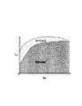
高負荷運転領域Hi−Loadは、エンジントルクTeとエンジン回転数Neのマップ上で予め規定されており、図2のROM20dの中に保持されている。ECU20は、エンジントルクとエンジン回転数から、現在の運転条件が高負荷運転領域Hi−Loadであるか、通常運転領域Normalであるかを判定する。
The high load operation region Hi-Load is defined in advance on the map of the engine torque Te and the engine speed Ne, and is held in the
この領域を規定する基準としては、例えば、全ての領域において高負荷用燃料噴射を行わないと仮定した場合に、各運転条件において熱効率が最も高くなる最適点火時期(MBT)と実際に設定する点火時期が等しい領域を通常運転領域、両者の値に差がある領域を高負荷運転領域とする。 As a standard for defining this region, for example, when it is assumed that high-load fuel injection is not performed in all regions, the optimum ignition timing (MBT) at which the thermal efficiency is the highest in each operating condition and the ignition actually set A region where the times are equal is a normal operation region, and a region where the two values are different is a high load operation region.
高負荷運転とは、火花点火機関の吸入空気量を制御するために備えられたスロットルの開度を全開にしている時、もしくは現在の運転条件において最も熱効率が高くなる最適点火時期よりも実際の点火時期を遅角側に設定している時である。 High-load operation means that the throttle opening provided to control the intake air amount of the spark ignition engine is fully opened, or the actual ignition condition is higher than the optimum ignition timing at which the thermal efficiency is the highest under the current operating conditions. This is when the ignition timing is set to the retard side.
次に、図4〜図7を用いて、本実施形態による火花点火式内燃機関の制御装置における燃料噴射方法について説明する。
最初に、図4を用いて、本実施形態による火花点火式内燃機関の制御装置における燃料噴射制御内容について説明する。
図4は、本発明の第1の実施形態による火花点火内燃機関の制御装置における燃料噴射制御内容を示すフローチャートである。
Next, the fuel injection method in the control device for the spark ignition type internal combustion engine according to the present embodiment will be described with reference to FIGS.
First, the fuel injection control contents in the control device for the spark ignition type internal combustion engine according to the present embodiment will be described with reference to FIG.
FIG. 4 is a flowchart showing the contents of fuel injection control in the control apparatus for the spark ignition internal combustion engine according to the first embodiment of the present invention.
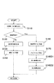
図4に示す制御内容は、ECU20によって、所定の周期で繰り返し実行される。
The control content shown in FIG. 4 is repeatedly executed by the
ステップS110において、ECU20は、現在のエンジン運転条件に関する情報(エンジン回転数、エンジントルクなど)を読み込む。
In step S110, the
次に、ステップS120において、ECU20は、予め記憶されたマップなどから、現在の運転条件が高負荷運転領域であるか否かを判定する。高負荷領域でない場合は、通常運転領域であると判断し、ステップ130において、ECU20は、通常燃料噴射制御を行う。通常燃料噴射制御の内容については、図5を用いて後述する。
Next, in step S120, the
これに対し、高負荷領域である場合、ステップ140において、ECU20は、高負荷用噴射制御Aを行う。通常燃料噴射制御の内容については、図6を用いて後述する。
On the other hand, in the case of the high load region, in
次に、図5を用いて、本実施形態による火花点火式内燃機関の制御装置による通常運転領域での燃料噴射制御内容について説明する。
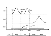
図5は、本発明の第1の実施形態による火花点火内燃機関の制御装置による通常運転領域での燃料噴射制御内容を示すタイミングチャートである。
Next, the fuel injection control contents in the normal operation region by the control device for the spark ignition type internal combustion engine according to the present embodiment will be described with reference to FIG.
FIG. 5 is a timing chart showing the contents of fuel injection control in the normal operation region by the control device for the spark ignition internal combustion engine according to the first embodiment of the present invention.
図5において、横軸は時間tを示している。図5(A)の縦軸はバルブリフト量Lvを示している。なお、図5(A)において、実線V−EXTは排気バルブのリフト量を示し、実線V−INTは吸気バルブのリフト量を示している。また、排気バルブと吸気バルブとの両方が開いている期間が、バルブオーバラップ期間V−ovlpである。図5(B)の縦軸は、シリンダ内圧力Pcを示している。図5(C)の縦軸は、燃料噴射信号Injを示している。 In FIG. 5, the horizontal axis indicates time t. The vertical axis in FIG. 5A indicates the valve lift amount Lv. In FIG. 5A, a solid line V-EXT indicates the lift amount of the exhaust valve, and a solid line V-INT indicates the lift amount of the intake valve. Further, a period in which both the exhaust valve and the intake valve are open is a valve overlap period V-ovlp. The vertical axis | shaft of FIG. 5 (B) has shown the cylinder internal pressure Pc. The vertical axis in FIG. 5C indicates the fuel injection signal Inj.
図5(A)の実線V−EXTに示すように、排気バルブは、膨張行程(EXP)の終盤で開き始め、吸気行程(INT)の初盤で閉じる。また、図5(A)の実線V−INTに示すように、吸気バルブは、排気行程(EXT)の終盤で開き始め、圧縮行程(CMP)の初盤で閉じる。従って、排気バルブと吸気バルブとの両方が開いているバルブオーバラップ期間V−ovlpが存在する。 As shown by a solid line V-EXT in FIG. 5A, the exhaust valve starts to open at the end of the expansion stroke (EXP) and closes at the first stage of the intake stroke (INT). Further, as shown by a solid line V-INT in FIG. 5A, the intake valve starts to open at the end of the exhaust stroke (EXT) and closes at the first stage of the compression stroke (CMP). Therefore, there is a valve overlap period V-ovlp in which both the exhaust valve and the intake valve are open.
図5(B)の実線は、シリンダ内圧力Pcの変化を示している。 The solid line in FIG. 5B indicates the change in the cylinder pressure Pc.
図5(C)に示すように、ECU20は、通常運転領域では、通常燃料噴射制御を行う。具体的には、充填効率の確保や混合気の均質化の観点から、基本的に吸気行程(INT)の中盤で燃料噴射を行う。
As shown in FIG. 5C, the
次に、図6を用いて、本実施形態による火花点火式内燃機関の制御装置による高負荷運転領域での燃料噴射制御内容について説明する。
図6は、本発明の第1の実施形態による火花点火内燃機関の制御装置による高負荷運転領域での燃料噴射制御内容を示すタイミングチャートである。
Next, the fuel injection control content in the high load operation region by the control device for the spark ignition type internal combustion engine according to the present embodiment will be described with reference to FIG.
FIG. 6 is a timing chart showing the fuel injection control contents in the high load operation region by the control device for the spark ignition internal combustion engine according to the first embodiment of the present invention.
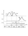
図6において、横軸は時間tを示している。図6(A)の縦軸はバルブリフト量Lvを示している。なお、図6(A)において、実線V−EXTは排気バルブのリフト量を示し、実線V−INTは吸気バルブのリフト量を示している。また、排気バルブと吸気バルブとの両方が開いている期間が、バルブオーバラップ期間V−ovlpである。図6(B)の縦軸は、シリンダ内圧力Pcを示している。図6(C)の縦軸は、燃料噴射信号Injを示している。 In FIG. 6, the horizontal axis indicates time t. The vertical axis in FIG. 6A indicates the valve lift amount Lv. In FIG. 6A, a solid line V-EXT indicates the lift amount of the exhaust valve, and a solid line V-INT indicates the lift amount of the intake valve. Further, a period in which both the exhaust valve and the intake valve are open is a valve overlap period V-ovlp. The vertical axis in FIG. 6B indicates the cylinder pressure Pc. The vertical axis in FIG. 6C indicates the fuel injection signal Inj.
図6(A)の実線V−EXTに示すように、排気バルブは、膨張行程(EXP)の終盤で開き始め、吸気行程(INT)の初盤で閉じる。また、図6(A)の実線V−INTに示すように、吸気バルブは、排気行程(EXT)の終盤で開き始め、圧縮行程(CMP)の初盤で閉じる。従って、排気バルブと吸気バルブとの両方が開いているバルブオーバラップ期間V−ovlpが存在する。 As shown by a solid line V-EXT in FIG. 6A, the exhaust valve starts to open at the end of the expansion stroke (EXP) and closes at the first stage of the intake stroke (INT). Further, as indicated by a solid line V-INT in FIG. 6A, the intake valve starts to open at the end of the exhaust stroke (EXT), and closes at the first plate of the compression stroke (CMP). Therefore, there is a valve overlap period V-ovlp in which both the exhaust valve and the intake valve are open.
図6(B)の実線は、シリンダ内圧力Pcの変化を示している。 A solid line in FIG. 6B indicates a change in the cylinder pressure Pc.
図6(C)に示すように、ECU20は、高負荷運転領域では、高負荷用燃料噴射制御Aを行う。具体的には、燃料噴射を2回に分割し、第1回目の噴射(第1噴射)INJ1の開始を上死点近傍とし、第2回目の噴射(第2噴射)INJ2の開始を吸気行程中盤から終盤に設定する。第1噴射INJ1は内部EGRへ向けた噴射を狙ったもので、気化冷却効果により効率的に内部EGRのみを冷却し、燃焼室内でのホットスポットの生成を抑制する。第2噴射INJ2は、空気と内部EGRの混合気を冷却し、燃焼室内の平均温度を低下させる。また、全ての燃料を吸気バルブが閉じるまでに噴射し終えることで、充填効率(トルク)を確保するとともに、燃料と新気の混合時間を確保して混合気の均質化を図り、排気の悪化を防止している。
As shown in FIG. 6C, the
次に、図7を用いて、本実施形態による火花点火式内燃機関の制御装置による高負荷運転領域における、第1噴射時の燃焼室内の状態について説明する。
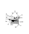
図7は、本発明の第1の実施形態による火花点火内燃機関の制御装置による高負荷運転領域における、第1噴射時の燃焼室内の状態の説明図である。なお、図1と同一符号は、同一部分を示している。
Next, the state in the combustion chamber at the time of the first injection in the high load operation region by the control device for the spark ignition internal combustion engine according to the present embodiment will be described with reference to FIG.
FIG. 7 is an explanatory diagram of a state in the combustion chamber at the time of the first injection in the high load operation region by the control device for the spark ignition internal combustion engine according to the first embodiment of the present invention. The same reference numerals as those in FIG. 1 indicate the same parts.
上死点TDCの近傍で燃料噴射を行うため、燃焼室に存在するガスの大部分が高温の内部EGR(Int−EGR)である。そのため、インジェクタ3から噴射する第1噴射INJ1の冷却効果を内部EGRに対してのみに適用することができる。
Since fuel injection is performed in the vicinity of the top dead center TDC, most of the gas present in the combustion chamber is high-temperature internal EGR (Int-EGR). Therefore, the cooling effect of the first injection INJ1 injected from the
ここで、内部EGRのみを効率的に冷却するためには、第1噴射開始時期を上死点前15°から上死点後15°の範囲となるように制御する必要がある。図6(A)に示したバルブオーバラップ期間V−ovlpが上死点前15°から上死点後15°の範囲である。第1噴射の開始時期は、バルブオーバラップ期間V−ovlp内であって、図6(C)に示したように、吸気上死点TDC−i付近とする。 Here, in order to efficiently cool only the internal EGR, it is necessary to control the first injection start timing so as to be in the range of 15 ° before top dead center to 15 ° after top dead center. The valve overlap period V-ovlp shown in FIG. 6A ranges from 15 ° before top dead center to 15 ° after top dead center. The start timing of the first injection is within the valve overlap period V-ovlp and is in the vicinity of the intake top dead center TDC-i as shown in FIG.
このように、上死点近傍にて燃料噴射をすると、ピストンとインジェクタとの距離が近いためにピストンへの燃料付着が生じやすい。そこで、図6(C)に示したように、第2噴射量(噴射パルス幅)INJ2に対して、第1噴射量(噴射パルス幅)INJ1を少なくすることで、燃料噴霧のペネトレーションを制御し、ピストンへの燃料付着を避けることができる。 As described above, when fuel is injected near the top dead center, the distance between the piston and the injector is short, so that fuel is likely to adhere to the piston. Therefore, as shown in FIG. 6C, the fuel spray penetration is controlled by reducing the first injection amount (injection pulse width) INJ1 with respect to the second injection amount (injection pulse width) INJ2. , Fuel adhesion to the piston can be avoided.
以上説明したように、本実施形態によれば、高負荷領域において排気行程が終了する上死点近傍で燃料噴射を行い、内部EGRを効率的に冷却することによって、燃焼室内のホットスポットの生成を抑え、ノックを抑制することができる。従って、点火リタード制御による熱効率およびトルクの低下を抑えることが可能となる。 As described above, according to this embodiment, the fuel injection is performed near the top dead center where the exhaust stroke ends in the high load region, and the internal EGR is efficiently cooled, thereby generating hot spots in the combustion chamber. And knocking can be suppressed. Accordingly, it is possible to suppress a decrease in thermal efficiency and torque due to ignition retard control.
また、残留ガスの吸引装置も不要である。 Also, a residual gas suction device is not required.
さらに、第2噴射INJ2の開始を吸気行程中盤から終盤としているため、すすの増加による排気ガスの悪化の問題も解消できる。 Furthermore, since the start of the second injection INJ2 is from the middle of the intake stroke to the end, the problem of exhaust gas deterioration due to an increase in soot can be solved.
次に、図8及び図9を用いて、本発明の第2の実施形態による火花点火式内燃機関の制御装置の構成及び動作について説明する。本実施形態による火花点火式内燃機関の制御装置を自動車用ガソリンエンジンに適用させたシステムの構成は、図1と同様である。本実施形態による火花点火式内燃機関の制御装置の構成は、図2と同様である。本実施形態による火花点火式内燃機関の制御装置における高負荷運転領域は、図3と同様である。本実施形態による火花点火式内燃機関の制御装置における燃料噴射制御内容は、図4と同様である。 Next, the configuration and operation of the control device for the spark ignition type internal combustion engine according to the second embodiment of the present invention will be described with reference to FIGS. The configuration of a system in which the control device for the spark ignition type internal combustion engine according to the present embodiment is applied to an automobile gasoline engine is the same as that shown in FIG. The configuration of the spark ignition type internal combustion engine control device according to the present embodiment is the same as that shown in FIG. The high load operation region in the control device for the spark ignition type internal combustion engine according to the present embodiment is the same as FIG. The fuel injection control content in the control device for the spark ignition type internal combustion engine according to the present embodiment is the same as in FIG.
図8は、本発明の第2の実施形態による火花点火内燃機関の制御装置による高負荷運転領域での燃料噴射制御内容を示すタイミングチャートである。図9は、本発明の第2の実施形態による火花点火内燃機関の制御装置による高負荷運転領域における、第1噴射時の燃焼室内の状態の説明図である。なお、図9において、図1と同一符号は、同一部分を示している。 FIG. 8 is a timing chart showing the fuel injection control contents in the high load operation region by the control device for the spark ignition internal combustion engine according to the second embodiment of the present invention. FIG. 9 is an explanatory diagram of the state in the combustion chamber at the time of the first injection in the high load operation region by the control device for the spark ignition internal combustion engine according to the second embodiment of the present invention. In FIG. 9, the same reference numerals as those in FIG. 1 denote the same parts.
本実施形態では、第1の実施形態とは、高負荷運転領域での燃料噴射制御内容が相違している。 In this embodiment, the fuel injection control content in the high load operation region is different from that of the first embodiment.
図8において、横軸は時間tを示している。図8(A)の縦軸はバルブリフト量Lvを示している。なお、図8(A)において、実線V−EXTは排気バルブのリフト量を示し、実線V−INTは吸気バルブのリフト量を示している。また、排気バルブと吸気バルブとの両方が開いている期間が、バルブオーバラップ期間V−ovlpである。図8(B)の縦軸は、シリンダ内圧力Pcを示している。図8(C)の縦軸は、燃料噴射信号Injを示している。 In FIG. 8, the horizontal axis represents time t. The vertical axis in FIG. 8A indicates the valve lift amount Lv. In FIG. 8A, a solid line V-EXT indicates the lift amount of the exhaust valve, and a solid line V-INT indicates the lift amount of the intake valve. Further, a period in which both the exhaust valve and the intake valve are open is a valve overlap period V-ovlp. The vertical axis | shaft of FIG. 8 (B) has shown the cylinder internal pressure Pc. The vertical axis in FIG. 8C indicates the fuel injection signal Inj.
図8(A)の実線V−EXTに示すように、排気バルブは、膨張行程(EXP)の終盤で開き始め、吸気行程(INT)の初盤で閉じる。また、図8(A)の実線V−INTに示すように、吸気バルブは、排気行程(EXT)の終盤で開き始め、圧縮行程(CMP)の初盤で閉じる。従って、排気バルブと吸気バルブとの両方が開いているバルブオーバラップ期間V−ovlpが存在する。 As shown by a solid line V-EXT in FIG. 8A, the exhaust valve starts to open at the end of the expansion stroke (EXP) and closes at the first stage of the intake stroke (INT). Further, as indicated by a solid line V-INT in FIG. 8A, the intake valve starts to open at the end of the exhaust stroke (EXT) and closes at the first stage of the compression stroke (CMP). Therefore, there is a valve overlap period V-ovlp in which both the exhaust valve and the intake valve are open.
図8(B)の実線は、シリンダ内圧力Pcの変化を示している。 A solid line in FIG. 8B indicates a change in the cylinder pressure Pc.
図8(C)に示すように、ECU20は、高負荷運転領域では、高負荷用燃料噴射制御Bを行う。具体的には、燃料噴射を2回に分割し、第1噴射INJ1の開始を排気弁が閉じた直後としている。第2噴射INJ2の開始は、第1の実施形態と同様に、吸気行程中盤から終盤に設定する。また、点火SPKの時期は、圧縮行程の終盤としている。
As shown in FIG. 8C, the
第1の実施形態同様、第1噴射INJ1は内部EGRへ向けた噴射を行うことで、燃焼室内でのホットスポットの生成を抑制し、第2噴射INJ2は、空気と内部EGRの混合気を冷却し、燃焼室内の平均温度を低下させる。また、全ての燃料を吸気バルブが閉じるまでに噴射し終えることで、充填効率(トルク)を確保するとともに、燃料と新気の混合時間を確保して混合気の均質化を図り、排気の悪化を防止している。 As in the first embodiment, the first injection INJ1 suppresses the generation of hot spots in the combustion chamber by performing injection toward the internal EGR, and the second injection INJ2 cools the mixture of air and internal EGR. And lowering the average temperature in the combustion chamber. In addition, by ensuring that all fuel is injected before the intake valve closes, the charging efficiency (torque) is ensured, and the mixing time of the fuel and fresh air is ensured to homogenize the air-fuel mixture and exhaust deterioration Is preventing.
次に、図9を用いて、本実施形態による高負荷運転領域における、第1噴射時の燃焼室内の状態について説明する。本実施形態では、排気バルブが閉じた後に第1燃料噴射INJ1を開始するため、燃料がそのまま排気バルブ8を通って排気管へ吹き抜けることを防止できる。さらに、上死点よりもピストンが下がった状態で燃料噴射を開始することになるため、ピストンへの燃料付着が起こりにくくなり第1噴射量を増量できる。従って、より大きい内部EGR冷却効果を得ることが可能となる。
Next, the state in the combustion chamber at the time of the first injection in the high load operation region according to the present embodiment will be described using FIG. In the present embodiment, since the first fuel injection INJ1 is started after the exhaust valve is closed, it is possible to prevent the fuel from being blown through the
本実施形態によれば、高負荷領域において排気バルブが閉じた直後に燃料噴射を開始して内部EGRを効率的に冷却することによって、燃焼室内のホットスポットの生成を抑えてノックを抑制できると同時に、排気管への燃料の吹き抜けを防止し、排気や燃費の悪化を避けることができる。 According to the present embodiment, the fuel injection is started immediately after the exhaust valve is closed in the high load region and the internal EGR is efficiently cooled, thereby suppressing the generation of hot spots in the combustion chamber and suppressing knocking. At the same time, fuel can be prevented from being blown into the exhaust pipe, and deterioration of exhaust and fuel consumption can be avoided.
また、第1噴射量を増量して、内部EGRの冷却効果を大きくすることができる。 Also, the cooling effect of the internal EGR can be increased by increasing the first injection amount.
また、残留ガスの吸引装置も不要である。 Also, a residual gas suction device is not required.
さらに、第2噴射INJ2の開始を吸気行程中盤から終盤としているため、すすの増加による排気ガスの悪化の問題も解消できる。 Furthermore, since the start of the second injection INJ2 is from the middle of the intake stroke to the end, the problem of exhaust gas deterioration due to an increase in soot can be solved.
次に、図10〜図12を用いて、本発明の第3の実施形態による火花点火式内燃機関の制御装置の構成及び動作について説明する。本実施形態による火花点火式内燃機関の制御装置を自動車用ガソリンエンジンに適用させたシステムの構成は、図1と同様である。本実施形態による火花点火式内燃機関の制御装置の構成は、図2と同様である。本実施形態による火花点火式内燃機関の制御装置における高負荷運転領域は、図3と同様である。 Next, the configuration and operation of the control device for the spark ignition internal combustion engine according to the third embodiment of the present invention will be described with reference to FIGS. The configuration of a system in which the control device for the spark ignition type internal combustion engine according to the present embodiment is applied to an automobile gasoline engine is the same as that shown in FIG. The configuration of the spark ignition type internal combustion engine control device according to the present embodiment is the same as that shown in FIG. The high load operation region in the control device for the spark ignition type internal combustion engine according to the present embodiment is the same as FIG.
図10は、本発明の第3の実施形態による火花点火内燃機関の制御装置における燃料噴射制御内容を示すフローチャートである。図11は、本発明の第3の実施形態による火花点火内燃機関の制御装置による高負荷運転領域での燃料噴射制御内容を示すタイミングチャートである。図12は、本発明の第3の実施形態による火花点火内燃機関の制御装置による高負荷運転領域における、第1噴射時の燃焼室内の状態の説明図である。なお、図12において、図1と同一符号は、同一部分を示している。 FIG. 10 is a flowchart showing the fuel injection control contents in the control apparatus for the spark ignition internal combustion engine according to the third embodiment of the present invention. FIG. 11 is a timing chart showing the fuel injection control contents in the high load operation region by the control device for the spark ignition internal combustion engine according to the third embodiment of the present invention. FIG. 12 is an explanatory diagram of the state in the combustion chamber at the time of the first injection in the high load operation region by the control device for the spark ignition internal combustion engine according to the third embodiment of the present invention. In FIG. 12, the same reference numerals as those in FIG. 1 denote the same parts.
本実施形態では、第1や第2の実施形態とは、高負荷運転領域での燃料噴射制御および可変バルブ制御内容が相違している。 In the present embodiment, the fuel injection control and variable valve control contents in the high load operation region are different from those in the first and second embodiments.
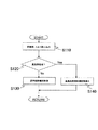
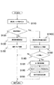
最初に、図10により、本実施形態による燃料噴射制御および可変バルブ制御処理の内容について説明する。図10に示す制御内容は、ECU20によって、所定の周期で繰り返し実行される。
First, the contents of the fuel injection control and variable valve control processing according to the present embodiment will be described with reference to FIG. The control content shown in FIG. 10 is repeatedly executed by the
ステップS110において、ECU20は、現在のエンジン運転条件に関する情報(エンジン回転数、エンジントルクなど)を読み込む。
In step S110, the
次に、ステップS120において、ECU20は、予め記憶されたマップなどから、現在の運転条件が高負荷運転領域であるか否かを判定する。高負荷領域でない場合は、通常運転領域であると判断し、ステップS130において、ECU20は、通常燃料噴射制御を行う。そして、ステップS150において、ECU20は、通常バルブ制御を行う。
Next, in step S120, the
これに対し、ステップS120で高負荷領域であると判定された場合、ステップS140Cにおいて、ECU20は、高負荷用噴射制御Cを行う。そして、ステップS160において、ECU20は、高負荷用バルブ制御を行う。
On the other hand, when it is determined in step S120 that the vehicle is in the high load region, in step S140C, the
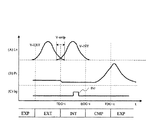
次に、図11において、横軸は時間tを示している。図11(A)の縦軸はバルブリフト量Lvを示している。なお、図11(A)において、実線V−EXTは排気バルブのリフト量を示し、実線V−INTは吸気バルブのリフト量を示している。また、排気バルブと吸気バルブとの両方が閉じている期間が、負のバルブオーバラップ期間V−mi−ovlpである。図11(B)の縦軸は、シリンダ内圧力Pcを示している。図11(C)の縦軸は、燃料噴射信号Injを示している。 Next, in FIG. 11, the horizontal axis indicates time t. The vertical axis in FIG. 11A indicates the valve lift amount Lv. In FIG. 11A, a solid line V-EXT indicates the lift amount of the exhaust valve, and a solid line V-INT indicates the lift amount of the intake valve. Further, a period in which both the exhaust valve and the intake valve are closed is a negative valve overlap period V-mi-ovlp. The vertical axis in FIG. 11B indicates the cylinder pressure Pc. The vertical axis in FIG. 11C indicates the fuel injection signal Inj.
ECU20は、高負荷運転領域では、高負荷用バルブ制御を行う。具体的には、図11(A)の実線V−INTに示すように、吸気バルブの開く時期を遅角化し、吸気バルブ及び排気バルブがともに閉じている期間である、負のオーバーラップ期間V−mi−ovlpを設けるよう、可変バルブを制御する。この時、図11(A)の実線V−EXTに示すように、排気バルブが閉じる時期は、内部EGRが出来る限り燃焼室に残留しないよう、吸気上死点TDC−i近傍に設定されている。
The
図11(B)の実線は、シリンダ内圧力Pcの変化を示している。 The solid line in FIG. 11B shows the change in the cylinder pressure Pc.
図11(C)に示すように、ECU20は、高負荷運転領域では、高負荷用燃料噴射制御Cを行う。具体的には、燃料噴射を分割し、第1噴射INJ1の開始を負のオーバーラップ期間V−mi−ovlpに設定し、第2噴射INJ2の開始は、第1や第2の実施形態と同様に、吸気行程中盤から終盤に設定する。
As shown in FIG. 11C, the
第1や第2の実施形態と同様に、第1噴射INJ1は内部EGRへ向けた噴射を行うことで、燃焼室内でのホットスポットの生成を抑制し、第2噴射INJ2は、空気と内部EGRの混合気を冷却し、燃焼室内の平均温度を低下させる。また、全ての燃料を吸気バルブが閉じるまでに噴射し終えることで、充填効率(トルク)を確保するとともに、燃料と新気の混合時間を確保して混合気の均質化を図り、排気の悪化を防止している。 Similar to the first and second embodiments, the first injection INJ1 performs injection toward the internal EGR, thereby suppressing the generation of hot spots in the combustion chamber, and the second injection INJ2 includes air and internal EGR. The air-fuel mixture is cooled to lower the average temperature in the combustion chamber. In addition, by ensuring that all fuel is injected before the intake valve closes, the charging efficiency (torque) is ensured, and the mixing time of the fuel and fresh air is ensured to homogenize the air-fuel mixture and exhaust deterioration Is preventing.
次に、図12を用いて、本実施形態による高負荷運転領域における、第1噴射時の燃焼室内の状態について説明する。本実施形態では、排気バルブの閉時期を吸気上死点TDC−iの近傍とし、吸気バルブの開時期を吸気上死点よりも遅角化することにより、上死点より後に負のオーバーラップ期間V−mi−ovlpを設けている。このようなバルブタイミングに設定することで、できる限り内部EGRを残留させずに、上死点以降も内部EGRのみが燃焼室内に存在する状態を長期間作ることができる。その上で、第1噴射INJ1を負のオーバーラップ期間中に開始することで、完全に内部EGRのみへ向けた噴射が可能となり、燃料の気化冷却効果を全て内部EGRに対して適用することが可能となる。 Next, the state in the combustion chamber at the time of the first injection in the high load operation region according to the present embodiment will be described with reference to FIG. In the present embodiment, the closing timing of the exhaust valve is set in the vicinity of the intake top dead center TDC-i, and the opening timing of the intake valve is retarded from the intake top dead center, thereby causing a negative overlap after the top dead center. A period V-mi-ovlp is provided. By setting such valve timing, it is possible to create a state in which only the internal EGR exists in the combustion chamber after the top dead center without causing the internal EGR to remain as long as possible. In addition, by starting the first injection INJ1 during the negative overlap period, it is possible to completely inject only the internal EGR, and the fuel evaporative cooling effect can be applied to the internal EGR. It becomes possible.
また、排気バルブが閉じた後に燃料噴射を開始するため、燃料がそのまま排気バルブを通って排気管へ吹き抜けることを防止できる。さらに、上死点よりもピストンが下がった状態で燃料噴射を開始することになるため、ピストンへの燃料付着が起こりにくくなり第1噴射量を増量できる。従って、より大きい内部EGR冷却効果を得ることが可能となる。 Further, since the fuel injection is started after the exhaust valve is closed, it is possible to prevent the fuel from being blown through the exhaust valve as it is to the exhaust pipe. Furthermore, since the fuel injection is started in a state where the piston is lowered from the top dead center, it is difficult for the fuel to adhere to the piston and the first injection amount can be increased. Therefore, a larger internal EGR cooling effect can be obtained.
さらに、吸気バルブを遅開きにすることにより、吸気行程初期に燃焼室内が負圧となるため、吸気バルブが開いた直後における、吸気管から燃焼室へ吸入される空気の流速が大きくなる。この現象により、燃焼室内に強い流動(乱れ)が生成されて内部EGRと空気との混合が促進され、ホットスポットの生成を抑えることもできる。 Furthermore, by slowly opening the intake valve, the pressure in the combustion chamber becomes negative at the beginning of the intake stroke, so that the flow rate of air drawn from the intake pipe into the combustion chamber immediately after the intake valve is opened increases. Due to this phenomenon, a strong flow (turbulence) is generated in the combustion chamber, the mixing of the internal EGR and air is promoted, and the generation of hot spots can also be suppressed.
本実施形態によれば、高負荷領域において、上死点以降に負のオーバーラップ期間を設け、その期間中に第1噴射を開始することで完全に内部EGRのみへ向けた噴射が可能となり、燃料の気化冷却効果の全てを内部EGRに対して適用することが可能となる。これにより、燃焼室内のホットスポットの生成を抑えてノックを抑制できると同時に、排気管への燃料の吹き抜けを防止し、排気や燃費の悪化を避けることができる。 According to the present embodiment, in the high load region, a negative overlap period is provided after the top dead center, and by starting the first injection during that period, it is possible to completely inject only to the internal EGR, All of the fuel evaporative cooling effect can be applied to the internal EGR. Thereby, generation of hot spots in the combustion chamber can be suppressed and knocking can be suppressed, and at the same time, fuel can be prevented from being blown into the exhaust pipe, and deterioration of exhaust gas and fuel consumption can be avoided.
また、第1噴射量を増量できるので、より大きい内部EGR冷却効果を得ることができる。 Further, since the first injection amount can be increased, a larger internal EGR cooling effect can be obtained.
さらに、吸気バルブを遅開きにすることにより、ホットスポットの生成を抑えることもできる。 Furthermore, the generation of hot spots can be suppressed by slowly opening the intake valve.
また、残留ガスの吸引装置も不要である。 Also, a residual gas suction device is not required.
さらに、第2噴射INJ2の開始を吸気行程中盤から終盤としているため、すすの増加による排気ガスの悪化の問題も解消できる。 Furthermore, since the start of the second injection INJ2 is from the middle of the intake stroke to the end, the problem of exhaust gas deterioration due to an increase in soot can be solved.
次に、図13及び図14を用いて、本発明の第4の実施形態による火花点火式内燃機関の制御装置の構成及び動作について説明する。本実施形態による火花点火式内燃機関の制御装置を自動車用ガソリンエンジンに適用させたシステムの構成は、図1と同様である。本実施形態による火花点火式内燃機関の制御装置の構成は、図2と同様である。本実施形態による火花点火式内燃機関の制御装置における高負荷運転領域は、図3と同様である。 Next, the configuration and operation of the control device for the spark ignition internal combustion engine according to the fourth embodiment of the present invention will be described with reference to FIGS. 13 and 14. The configuration of a system in which the control device for the spark ignition type internal combustion engine according to the present embodiment is applied to an automobile gasoline engine is the same as that shown in FIG. The configuration of the spark ignition type internal combustion engine control device according to the present embodiment is the same as that shown in FIG. The high load operation region in the control device for the spark ignition type internal combustion engine according to the present embodiment is the same as FIG.
図13は、本発明の第4の実施形態による火花点火内燃機関の制御装置における燃料噴射制御内容を示すフローチャートである。図14は、本発明の第4の実施形態による火花点火内燃機関の制御装置による高負荷運転領域での燃料噴射制御内容を示すタイミングチャートである。 FIG. 13 is a flowchart showing the contents of fuel injection control in the control apparatus for a spark ignition internal combustion engine according to the fourth embodiment of the present invention. FIG. 14 is a timing chart showing the fuel injection control contents in the high load operation region by the control device for the spark ignition internal combustion engine according to the fourth embodiment of the present invention.
図10〜図12にて説明した第3の実施形態では、1サイクルおきに設定を切り替えることが可能な燃料噴射制御(第1噴射量制御)に対し、同じく1サイクルおきに設定を切り替えることが可能な高応答の可変バルブ機構を想定していたため、両者の目標値を同時に切り替えることが可能であった。 In the third embodiment described with reference to FIGS. 10 to 12, the setting can be switched every other cycle as opposed to the fuel injection control (first injection amount control) in which the setting can be switched every other cycle. Since a possible variable valve mechanism with high response was assumed, it was possible to simultaneously switch the target values of both.
それに対して、本実施形態では、目標値を変更した際に、目標値に到達するまで最低でも数サイクルの期間を必要とする可変バルブ機構を搭載したエンジンを想定する。この場合、燃料噴射量とバルブタイミングの目標値を同時に切り替えると、燃料噴射量に対してバルブタイミングに遅れが生じ、バルブタイミングが目標値に達するまでの期間において、ピストン付着などの問題が発生する。 On the other hand, in this embodiment, when the target value is changed, an engine equipped with a variable valve mechanism that requires a period of several cycles at the minimum to reach the target value is assumed. In this case, if the fuel injection amount and the target value of the valve timing are switched simultaneously, the valve timing is delayed with respect to the fuel injection amount, and problems such as piston adhesion occur during the period until the valve timing reaches the target value. .
そこで、本実施形態では、高負荷領域での燃料噴射制御方法が、第3の実施形態とは異なる。具体的には、運転条件の変化などにより目標値の変更があった際、バルブタイミング(例えば排気バルブの閉じる時期)の応答速度に合わせて第1噴射量を徐々に増量させるとともに、バルブタイミングが目標値に達するまでの間、過渡的なノックを抑制するために、点火時期を一時的に現在の運転条件における目標値よりもリタードする。 Therefore, in the present embodiment, the fuel injection control method in the high load region is different from that in the third embodiment. Specifically, when the target value is changed due to a change in operating conditions or the like, the first injection amount is gradually increased in accordance with the response speed of the valve timing (for example, the closing timing of the exhaust valve), and the valve timing is In order to suppress a transient knock until reaching the target value, the ignition timing is temporarily retarded from the target value under the current operating conditions.
最初に、図13により、本実施形態による燃料噴射制御および可変バルブ制御処理の内容について説明する。図13に示す制御内容は、ECU20によって、所定の周期で繰り返し実行される。
First, the contents of fuel injection control and variable valve control processing according to this embodiment will be described with reference to FIG. The control content shown in FIG. 13 is repeatedly executed by the
ステップS110において、ECU20は、現在のエンジン運転条件に関する情報(エンジン回転数、エンジントルクなど)を読み込む。
In step S110, the
次に、ステップS120において、ECU20は、予め記憶されたマップなどから、現在の運転条件が高負荷運転領域であるか否かを判定する。高負荷領域でない場合は、通常運転領域であると判断し、ステップS130において、ECU20は、通常燃料噴射制御を行う。そして、ステップS150において、ECU20は、通常バルブ制御を行う。
Next, in step S120, the
これに対し、ステップS120で高負荷領域であると判定された場合、ステップS160において、ECU20は、高負荷用バルブ制御を行う。
On the other hand, if it is determined in step S120 that the region is a high load region, in step S160, the
次に、ステップS170において、ECU20は、現在のバルブタイミングを検出する。
Next, in step S170, the
次に、ステップS140D1において、ECU20は、ステップS170で検出された現在のバルブタイミングに基づいて、第1噴射量を決定する。さらに、ステップS140D2において、ECU20は、現在のバルブタイミングに基づいて、現在の運転条件での点火時期設定値に対する点火リタード量を決定する。
Next, in step S140D1, the
次に、図14において、横軸は時間tを示している。図11(A)の縦軸はバルブリフト量Lvを示している。ここでは、排気バルブの閉じるタイミングを例にして図示している。図14(A)において、破線は、排気バルブのバルブリフト量の指令値Lv−istを示している。実線は、排気バルブのバルブリフト量の実測値Lv−msを示している。図14(A)に破線で示すように、排気バルブのバルブリフト量の指令値Lv−istを可変バルブ機構に指令を出力しても、可変バルブ機構のバルブタイミングに遅れにより、実際のバルブリフト量は、実線で示すバルブリフト量の実測値Lv−msのように変化する。このバルブリフト量の実測値Lv−msは、図13のステップS170によって、バルブタイミングとして検出される。 Next, in FIG. 14, the horizontal axis indicates time t. The vertical axis in FIG. 11A indicates the valve lift amount Lv. Here, the closing timing of the exhaust valve is illustrated as an example. In FIG. 14A, a broken line indicates a command value Lv-ist of the valve lift amount of the exhaust valve. The solid line indicates the actual measurement value Lv-ms of the valve lift amount of the exhaust valve. As indicated by a broken line in FIG. 14A, even if a command value Lv-ist for the valve lift amount of the exhaust valve is output to the variable valve mechanism, the actual valve lift is delayed due to a delay in the valve timing of the variable valve mechanism. The amount changes like a measured value Lv-ms of the valve lift amount indicated by a solid line. The actual measured value Lv-ms of the valve lift amount is detected as the valve timing in step S170 of FIG.
また、図14(B)の縦軸は、燃料噴射信号Injを示している。 Moreover, the vertical axis | shaft of FIG.14 (B) has shown the fuel-injection signal Inj.
図14(B)に示すように、ECU20は、高負荷運転領域では、高負荷用燃料噴射制御D及び点火時期制御を行う。具体的には、図11(C)と同様に、燃料噴射を分割し、第1噴射INJ1の開始を負のオーバーラップ期間V−mi−ovlpに設定し、第2噴射INJ2の開始は、吸気行程中盤から終盤に設定する。
As shown in FIG. 14B, the
ここで、膨張行程−排気行程−吸気行程−圧縮行程を1サイクルとして、通常運転領域Normalから高負荷運転領域H−Loadに切り替わった時を、第1サイクルとし、順次、第2サイクル、第3サイクルと続く場合、第1サイクルにおける第1噴射INJ1−1の噴射量(図14(B)における第1噴射INJ1−1のパルスの幅)に対して、第2サイクルにおける第1噴射INJ1−2の噴射量(図14(B)における第1噴射INJ1−2のパルスの幅)を増加させる。さらに、第2サイクルにおける第1噴射INJ1−2の噴射量(図14(B)における第1噴射INJ1−2のパルスの幅)に対して、第3サイクルにおける第1噴射INJ1−3の噴射量(図14(B)における第1噴射INJ1−3のパルスの幅)を増加させる。このように、バルブリフト量の応答遅れに応じて、第1噴射INJ1の噴射量を徐々に増加させる。 Here, the expansion stroke-exhaust stroke-intake stroke-compression stroke is defined as one cycle, and when the normal operation region Normal is switched to the high load operation region H-Load, the first cycle is designated as the second cycle, the third cycle. When the cycle continues, the first injection INJ1-2 in the second cycle with respect to the injection amount of the first injection INJ1-1 in the first cycle (the pulse width of the first injection INJ1-1 in FIG. 14B). Is increased (the pulse width of the first injection INJ1-2 in FIG. 14B). Furthermore, with respect to the injection amount of the first injection INJ1-2 in the second cycle (the pulse width of the first injection INJ1-2 in FIG. 14B), the injection amount of the first injection INJ1-3 in the third cycle (The pulse width of the first injection INJ1-3 in FIG. 14B) is increased. Thus, the injection amount of the first injection INJ1 is gradually increased according to the response delay of the valve lift amount.
また、点火時期について見ると、第1サイクルにおける点火SPK−1の時期は、圧縮行程の終盤としている。これは、現在の運転条件における目標値SPK−tgtよりもリタードしたタイミングである。そして、第1サイクルにおける点火SPK−1の時期に対して、第2サイクルにおける点火SPK−2の時期を少し進角させ、現在の運転条件における目標値SPK−tgtに近づける。さらに、第2サイクルにおける点火SPK−2の時期に対して、第3サイクルにおける点火SPK−3の時期を進角させ、図示の状態では、現在の運転条件における目標値に一致している。 Looking at the ignition timing, the timing of the ignition SPK-1 in the first cycle is at the end of the compression stroke. This is the timing retarded from the target value SPK-tgt under the current operating conditions. Then, the timing of the ignition SPK-2 in the second cycle is slightly advanced with respect to the timing of the ignition SPK-1 in the first cycle, and approaches the target value SPK-tgt in the current operating conditions. Further, the timing of the ignition SPK-3 in the third cycle is advanced with respect to the timing of the ignition SPK-2 in the second cycle.
本実施形態でも、第1噴射INJ1は内部EGRへ向けた噴射を行うことで、燃焼室内でのホットスポットの生成を抑制し、第2噴射INJ2は、空気と内部EGRの混合気を冷却し、燃焼室内の平均温度を低下させる。 Also in this embodiment, the first injection INJ1 performs injection toward the internal EGR, thereby suppressing the generation of hot spots in the combustion chamber, and the second injection INJ2 cools the mixture of air and internal EGR, Reduce the average temperature in the combustion chamber.
また、バルブタイミングの応答速度に合わせて、第1噴射量を徐々に増量させるとともに、バルブタイミングが目標値に達するまでの間、過渡的なノックを抑制するために、点火時期を一時的に現在の運転条件における目標値よりもリタードする。 In addition, the first injection amount is gradually increased according to the response speed of the valve timing, and the ignition timing is temporarily set in order to suppress transient knock until the valve timing reaches the target value. It retards more than the target value in the operating conditions.
本実施形態によれば、高負荷領域において、第1噴射を内部EGRに向けて噴射することで、燃料の気化冷却効果の全てを内部EGRに対して適用することが可能となる。これにより、燃焼室内のホットスポットの生成を抑えてノックを抑制できると同時に、排気管への燃料の吹き抜けを防止し、排気や燃費の悪化を避けることができる。 According to this embodiment, it is possible to apply all of the fuel evaporative cooling effect to the internal EGR by injecting the first injection toward the internal EGR in the high load region. Thereby, generation of hot spots in the combustion chamber can be suppressed and knocking can be suppressed, and at the same time, fuel can be prevented from being blown into the exhaust pipe, and deterioration of exhaust gas and fuel consumption can be avoided.
また、高負荷領域において運転条件が変化した際に、可変バルブ機構の応答性を考慮して、燃料噴射制御および点火リタード制御を行うことで、バルブタイミングが目標値に達するまでの期間における過渡的なノックや排気悪化を抑制することができる。 In addition, when the operating conditions change in the high load region, the fuel injection control and ignition retard control are performed in consideration of the responsiveness of the variable valve mechanism, so that the transient in the period until the valve timing reaches the target value. It is possible to suppress knocking and exhaust deterioration.
また、残留ガスの吸引装置も不要である。 Also, a residual gas suction device is not required.
さらに、第2噴射INJ2の開始を吸気行程中盤から終盤としているため、すすの増加による排気ガスの悪化の問題も解消できる。 Furthermore, since the start of the second injection INJ2 is from the middle of the intake stroke to the end, the problem of exhaust gas deterioration due to an increase in soot can be solved.
次に、図15〜図18を用いて、本発明の第5の実施形態による火花点火式内燃機関の制御装置の構成及び動作について説明する。本実施形態による火花点火式内燃機関の制御装置の構成は、図2と同様である。本実施形態による火花点火式内燃機関の制御装置における高負荷運転領域は、図3と同様である。 Next, the configuration and operation of the control device for the spark ignition type internal combustion engine according to the fifth embodiment of the present invention will be described with reference to FIGS. The configuration of the spark ignition type internal combustion engine control device according to the present embodiment is the same as that shown in FIG. The high load operation region in the control device for the spark ignition type internal combustion engine according to the present embodiment is the same as FIG.
最初に、図15を用いて、本実施形態による火花点火式内燃機関の制御装置を自動車用ガソリンエンジンに適用させたシステムの構成について説明する。
図15は、本発明の第1の実施形態による火花点火式内燃機関の制御装置を自動車用ガソリンエンジンに適用させたシステムの構成を示すシステム構成図である。なお、図1と同一符号は、同一部分を示している。
First, the configuration of a system in which the control device for the spark ignition internal combustion engine according to the present embodiment is applied to an automobile gasoline engine will be described with reference to FIG.
FIG. 15 is a system configuration diagram showing a configuration of a system in which the control device for the spark ignition type internal combustion engine according to the first embodiment of the present invention is applied to an automobile gasoline engine. The same reference numerals as those in FIG. 1 indicate the same parts.
本実施形態では、図1に示した内燃機関のシステム構成に対して、さらに、ノックセンサ15を備えたものである。ノックセンサ15は、シリンダ7の適宜位置にを備えている。ノックセンサ15は、エンジン100の振動状態を計測するもので、この出力信号に基づいて、ECU20は、エンジン100においてノックが生じているか否かを判定する。
In the present embodiment, a
次に、図16〜図18を用いて、本実施形態による火花点火内燃機関の制御装置による燃料噴射制御内容について説明する。
図16は、本発明の第5の実施形態による火花点火内燃機関の制御装置における燃料噴射制御内容を示すフローチャートである。図17は、本発明の第5の実施形態による火花点火内燃機関の制御装置による通常運転領域での燃料噴射制御内容を示すタイミングチャートである。図18は、本発明の第5の実施形態による火花点火内燃機関の制御装置による高負荷運転領域での燃料噴射制御内容を示すタイミングチャートである。
Next, the contents of fuel injection control by the control device for the spark ignition internal combustion engine according to the present embodiment will be described with reference to FIGS.
FIG. 16 is a flowchart showing the contents of fuel injection control in the control apparatus for a spark ignition internal combustion engine according to the fifth embodiment of the present invention. FIG. 17 is a timing chart showing the contents of fuel injection control in the normal operation region by the controller for the spark ignition internal combustion engine according to the fifth embodiment of the present invention. FIG. 18 is a timing chart showing the fuel injection control contents in the high load operation region by the control device for the spark ignition internal combustion engine according to the fifth embodiment of the present invention.
最初に、図16により、本実施形態による燃料噴射制御および可変バルブ制御処理の内容について説明する。図16に示す制御内容は、ECU20によって、所定の周期で繰り返し実行される。
First, the contents of fuel injection control and variable valve control processing according to the present embodiment will be described with reference to FIG. The control content shown in FIG. 16 is repeatedly executed by the
ステップS110において、ECU20は、現在のエンジン運転条件に関する情報(エンジン回転数、エンジントルクなど)を読み込む。
In step S110, the
次に、ステップS120において、ECU20は、予め記憶されたマップなどから、現在の運転条件が高負荷運転領域であるか否かを判定する。高負荷領域でない場合は、通常運転領域であると判断し、ステップS130において、ECU20は、通常燃料噴射制御を行う。そして、ステップS150において、ECU20は、通常バルブ制御を行う。
Next, in step S120, the
これに対し、ステップS120において高負荷領域であると判定された場合、ステップS140Cにおいて、ECU20は、図10及び図11にて説明したように、高負荷用噴射制御Cを行う。そして、ステップS160において、ECU20は、高負荷用バルブ制御を行う。
On the other hand, when it is determined in step S120 that the vehicle is in the high load region, in step S140C, the
次に、ステップS180において、ECU20は、現在ノックが検出されているか否かを判定する。ノックが検出されている場合は、ステップS185において、ECU20は、第1噴射量を増量する。その後、さらに、ステップS190において、ECU20は、負のオーバーラップ期間を長期化し、さらに、ステップS185において、ECU20は、現在の噴射量およびバルブタイミングの設定値を記憶する。
Next, in step S180, the
図17は、ノックが発生していない場合の、高負荷運転領域におけるタイムチャートである。この時の燃料噴射およびバルブの設定は、第3の実施形態と同様である。図18は、ノックが発生した場合の、高負荷運転領域におけるタイムチャートである。 FIG. 17 is a time chart in the high-load operation region when knocking does not occur. The fuel injection and valve settings at this time are the same as in the third embodiment. FIG. 18 is a time chart in the high load operation region when knocking occurs.
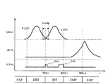
図17及び図18において、横軸は時間tを示している。図17(A)及び図18(A)の縦軸はバルブリフト量Lvを示している。なお、図17(A)及び図18(A)において、実線V−EXTは排気バルブのリフト量を示し、実線V−INTは吸気バルブのリフト量を示している。また、排気バルブと吸気バルブとの両方が閉じている期間が、負のバルブオーバラップ期間V−mi−ovlpである。図17(B)及び図18(B)の縦軸は、シリンダ内圧力Pcを示している。図17(C)及び図18(C)の縦軸は、燃料噴射信号Injを示している。 17 and 18, the horizontal axis indicates time t. The vertical axis | shaft of FIG. 17 (A) and FIG. 18 (A) has shown the valve lift amount Lv. In FIGS. 17A and 18A, a solid line V-EXT indicates the lift amount of the exhaust valve, and a solid line V-INT indicates the lift amount of the intake valve. Further, a period in which both the exhaust valve and the intake valve are closed is a negative valve overlap period V-mi-ovlp. The vertical axis | shaft of FIG. 17 (B) and FIG. 18 (B) has shown the cylinder internal pressure Pc. The vertical axes in FIGS. 17C and 18C indicate the fuel injection signal Inj.
図17においては、ノックが発生していない場合であり、高負荷運転領域における、燃料噴射およびバルブの設定は、第3の実施形態と同様である。 In FIG. 17, there is no knocking, and fuel injection and valve setting in the high-load operation region are the same as in the third embodiment.
図18は、ノックが発生した場合を示しており、ノックが発生すると、図18(C)に示すように、第1噴射INJ1’の噴射量を増量する。この時、第1噴射量を増量した分だけ、第2噴射INJ2’の噴射量を減量する。また、第1噴射量の増量に伴って、図18(A)に示すように、吸気バルブV−INTが開く時期を遅らせて、負のオーバーラップ期間V−mi−ovlpを長期化する。 FIG. 18 shows a case where knocking occurs. When knocking occurs, the injection amount of the first injection INJ1 'is increased as shown in FIG. 18C. At this time, the injection amount of the second injection INJ2 'is decreased by an amount corresponding to the increase in the first injection amount. Further, as the first injection amount increases, as shown in FIG. 18A, the opening time of the intake valve V-INT is delayed and the negative overlap period V-mi-ovlp is lengthened.
このような制御により、エンジン100の経年変化や環境変化により、エンジン100の耐ノック性能に変化が生じた際にも、第1噴射量および負のオーバーラップ量を適正に制御して、壁面付着を抑えつつ内部EGRを冷却することで、耐ノック性能を維持することが可能となる。
By such control, even when a change in the anti-knock performance of the
なお、以上の説明では、エンジンの振動を検知するノックセンサ15による検出結果に基づき、第1燃料噴射量や負のオーバーラップ量の変更を行ったが、筒内圧力センサ信号を用いたノック検出結果もしくはノック前兆検出結果に基づき、第1燃料噴射量や負のオーバーラップ量の変更を行ってもよい。
In the above description, the first fuel injection amount and the negative overlap amount are changed based on the detection result by the
また、ノックを検出した際、第1燃料噴射量や負のオーバーラップ期間の変更のみによりノックを回避しているが、これら噴射およびバルブ制御を、通常の点火リタードによるノック回避制御と組み合わせて行ってもよい。 In addition, when a knock is detected, the knock is avoided only by changing the first fuel injection amount and the negative overlap period. However, these injection and valve control are performed in combination with the knock avoidance control by the normal ignition retard. May be.
また、1サイクルおきに設定を変更することが可能な高応答可変バルブ機構を搭載したエンジンシステムを想定したが、第4の実施形態のように、目標値に到達するまで最低でも数サイクルの期間を必要とする可変バルブ機構を搭載したエンジンである場合は、まずバルブ制御を先行して行い、検出された現在の負のオーバーラップ量に基づいて、第1噴射量を決定するようにしてもよい。さらに、負のオーバーラップ量が目標値に達するまでの期間は、過渡時のノックを抑制するために、点火時期をリタード制御してもよい。 In addition, an engine system equipped with a highly responsive variable valve mechanism capable of changing the setting every other cycle is assumed. As in the fourth embodiment, a period of at least several cycles until the target value is reached. In the case of an engine equipped with a variable valve mechanism that requires the first, the valve control is performed first, and the first injection amount is determined based on the detected current negative overlap amount. Good. Further, during the period until the negative overlap amount reaches the target value, the ignition timing may be retarded to suppress knocking during transition.
以上説明したように、本実施形態によれば、ノック検出時に、第1噴射を増量し、それに応じて負のオーバーラップ期間を長期化することで、エンジンの経年変化や環境変化により、エンジンの耐ノック性能に変化が生じた際にも、燃料による冷却効果を最適に制御して、排気の悪化や熱効率の低下を抑えつつ、ノックを抑制することができる。 As described above, according to the present embodiment, when the knock is detected, the first injection is increased, and the negative overlap period is lengthened accordingly. Even when there is a change in the anti-knock performance, the cooling effect by the fuel can be optimally controlled to suppress the knock while suppressing the deterioration of exhaust gas and the decrease in thermal efficiency.
また、残留ガスの吸引装置も不要である。 Also, a residual gas suction device is not required.
さらに、第2噴射INJ2の開始を吸気行程中盤から終盤としているため、すすの増加による排気ガスの悪化の問題も解消できる。 Furthermore, since the start of the second injection INJ2 is from the middle of the intake stroke to the end, the problem of exhaust gas deterioration due to an increase in soot can be solved.
なお、本発明は、前記各実施形態に限定されるものではなく、特許請求の範囲に記載された発明の精神を逸脱しない範囲で、設計において種々の変更ができる。
The present invention is not limited to the above embodiments, and various changes can be made in the design without departing from the spirit of the invention described in the claims.
1…エアフローセンサ
2…電子制御スロットル
3…インジェクタ
4…点火プラグ
5…可変バルブ
5a…吸気バルブ
5b…排気バルブ
6…吸気管
7…シリンダ
8…排気管
9…空燃比センサ
10…三元触媒
11…排気温度センサ
12…クランク軸
13…クランク角度センサ
14…ピストン
15…ノックセンサ
20…ECU
100…エンジン
201…入力回路
202…入力ポート
203…RAM
204…ROM
205…CPU
206…電子スロットル開路
207…インジェクタ駆動回路
208…点火出力回路
209…可変バルブ駆動回路
DESCRIPTION OF SYMBOLS 1 ...
DESCRIPTION OF
204 ... ROM
205 ... CPU
206 ... Electronic throttle opening 207 ... Injector drive circuit 208 ... Ignition output circuit 209 ... Variable valve drive circuit
Claims (8)
前記火花点火式内燃機関は、吸気弁及び排気弁の開閉時期を制御可能な可変動弁機構を備え、
前記火花点火機関が高負荷運転する時に、
燃料を複数回に分割して噴射するとともに、
第1回目の燃料噴射を、吸気上死点を含み前記吸気弁及び前記排気弁が共に開いている正のオーバーラップ期間中、又は、前記吸気弁及び前記排気弁が共に閉じている負のオーバーラップ期間中に、前記火花点火機関の燃焼室内に存在する内部EGRへ向けて行う制御手段を備え、
前記制御手段は、前記第1回目の燃料噴射を、排気行程が終了する吸気上死点を基準として、クランク角で−15°から+15°の間に開始することを特徴とする火花点火式内燃機関の制御装置。 An in-cylinder injection type spark ignition type internal combustion engine control device,
The spark ignition internal combustion engine includes a variable valve mechanism that can control opening and closing timings of an intake valve and an exhaust valve,
When the spark ignition engine operates at a high load,
Fuel is divided into multiple injections and
The first fuel injection is performed during a positive overlap period in which both the intake valve and the exhaust valve are open, including the intake top dead center, or a negative overload in which both the intake valve and the exhaust valve are closed. during overlap period, Bei give a control means for performing towards internal EGR present in the combustion chamber of the spark-ignition engine,
The spark ignition type internal combustion engine characterized in that the control means starts the first fuel injection between −15 ° and + 15 ° in crank angle with reference to an intake top dead center at which an exhaust stroke ends. Engine control device.
前記制御手段は、前記第1回目の燃料噴射を排気行程が終了する吸気上死点近傍に開始するように制御することを特徴とする火花点火式内燃機関の制御装置。 Te controller smell of a spark ignition type internal combustion engine according to claim 1,
Before SL control means before Symbol control apparatus for a spark ignition internal combustion engine in which the exhaust stroke of the fuel injection of the first time, characterized in that the control to start near intake top dead center to end.
前記制御手段は、前記吸気弁が開く時期が吸気上死点よりも遅角側になるように前記可変動弁を制御して、前記負のオーバーラップ期間が吸気上死点より遅角側になるよう設定するとともに、
前記第1回目の燃料噴射を前記負のオーバーラップ期間に開始するように制御することを特徴とする火花点火式内燃機関の制御装置。 The control device for a spark ignition type internal combustion engine according to claim 1 ,
The control means controls the variable valve so that the timing when the intake valve opens is retarded from the intake top dead center, and the negative overlap period is retarded from the intake top dead center. As well as
A control device for a spark ignition type internal combustion engine, characterized in that the first fuel injection is controlled to start during the negative overlap period.
前記火花点火機関は、現在のバルブタイミングを検出するバルブタイミング検出手段を備え、
前記制御手段は、前記火花点火機関が高負荷運転する時に、前記バルブタイミング検出手段によって検出されたバルブタイミングに基づいて、前記第1回目の燃料噴射量を決定することを特徴とする火花点火式内燃機関の制御装置。 The control apparatus according to claim 2 Symbol placement of a spark ignition type internal combustion engine,
The spark ignition engine includes valve timing detection means for detecting a current valve timing,
The control means determines the first fuel injection amount based on the valve timing detected by the valve timing detection means when the spark ignition engine operates at a high load. Control device for internal combustion engine.
前記制御手段は、前記バルブタイミング検出手段によって検出された現在のバルブタイミングが、バルブタイミングの目標値に到達するまでの期間は、現在の運転条件における点火時期の設定値よりも点火時期を遅角するように制御することを特徴とする火花点火式内燃機関の制御装置。 The control device for a spark ignition type internal combustion engine according to claim 4 ,
The control means retards the ignition timing from the set value of the ignition timing under the current operating conditions during a period until the current valve timing detected by the valve timing detection means reaches a target value of the valve timing. A control device for a spark ignition type internal combustion engine, characterized in that the control is carried out.
前記高負荷運転とは、前記火花点火機関の吸入空気量を制御するために備えられたスロットルの開度を全開にしている時、もしくは現在の運転条件において最も熱効率が高くなる最適点火時期よりも実際の点火時期を遅角側に設定している時、のうちのいずれかであることを特徴とする火花点火式内燃機関の制御装置。 The control device for a spark ignition type internal combustion engine according to claim 1,
The high load operation means that the throttle opening provided for controlling the intake air amount of the spark ignition engine is fully opened, or the optimum ignition timing at which the thermal efficiency is the highest under the current operating conditions. A control device for a spark ignition type internal combustion engine, characterized in that the actual ignition timing is set to one of the retarded angle side.
前記火花点火機関は、ノックを検出するノック検出手段を備え、
前記制御手段は、前記ノック検出手段によってノックが生じていると判定された時に、前記第1回目の燃料噴射の噴射量を増量するように制御することを特徴とする火花点火式内燃機関の制御装置。 The control device for a spark ignition type internal combustion engine according to claim 1,
The spark ignition engine includes knock detection means for detecting knock,
The control means controls the spark ignition type internal combustion engine to increase the injection amount of the first fuel injection when it is determined by the knock detection means that knocking has occurred. apparatus.
前記制御手段は、前記ノック検出手段によってノックが生じていると判定された時に、前記第1回目の燃料噴射の噴射量を増量するように制御するとともに、前記負のオーバーラップ期間を長期化するよう制御することを特徴とする火花点火式内燃機関の制御装置。 The control device for a spark ignition type internal combustion engine according to claim 7 ,
The control means controls to increase the injection amount of the first fuel injection when the knock detection means determines that a knock has occurred, and prolongs the negative overlap period. A control apparatus for a spark ignition internal combustion engine, characterized in that
Priority Applications (2)
| Application Number | Priority Date | Filing Date | Title |
|---|---|---|---|
| JP2007316923A JP4863980B2 (en) | 2007-12-07 | 2007-12-07 | Control device for spark ignition internal combustion engine |
| US12/329,386 US8078387B2 (en) | 2007-12-07 | 2008-12-05 | Control apparatus for spark-ignition engine |
Applications Claiming Priority (1)
| Application Number | Priority Date | Filing Date | Title |
|---|---|---|---|
| JP2007316923A JP4863980B2 (en) | 2007-12-07 | 2007-12-07 | Control device for spark ignition internal combustion engine |
Publications (2)
| Publication Number | Publication Date |
|---|---|
| JP2009138655A JP2009138655A (en) | 2009-06-25 |
| JP4863980B2 true JP4863980B2 (en) | 2012-01-25 |
Family
ID=40722473
Family Applications (1)
| Application Number | Title | Priority Date | Filing Date |
|---|---|---|---|
| JP2007316923A Expired - Fee Related JP4863980B2 (en) | 2007-12-07 | 2007-12-07 | Control device for spark ignition internal combustion engine |
Country Status (2)
| Country | Link |
|---|---|
| US (1) | US8078387B2 (en) |
| JP (1) | JP4863980B2 (en) |
Families Citing this family (19)
| Publication number | Priority date | Publication date | Assignee | Title |
|---|---|---|---|---|
| JP2009024682A (en) * | 2007-07-24 | 2009-02-05 | Denso Corp | Control device for spray guide type cylinder injection internal combustion engine |
| US7720593B2 (en) * | 2007-10-02 | 2010-05-18 | Ford Global Technologies, Llc | Fuel injection strategy for gasoline direct injection engine during high speed/load operation |
| JP5046190B2 (en) * | 2008-01-22 | 2012-10-10 | スズキ株式会社 | In-cylinder injection internal combustion engine control device |
| CN101946074B (en) * | 2008-02-15 | 2013-03-13 | 通用汽车环球科技运作公司 | Method for controlling a spark-ignition direct-injection internal combustion engine at low loads |
| US8316819B2 (en) * | 2008-09-26 | 2012-11-27 | Mazda Motor Corporation | Control of spark ignited internal combustion engine |
| JP5334791B2 (en) * | 2009-10-19 | 2013-11-06 | 三菱電機株式会社 | Control device for internal combustion engine |
| JP5293638B2 (en) * | 2010-02-25 | 2013-09-18 | 三菱自動車工業株式会社 | Engine valve timing control device |
| US20130263819A1 (en) * | 2010-12-28 | 2013-10-10 | Toyota Jidosha Kabushiki Kaisha | Direct-injection internal combustion engine |
| JP2012149552A (en) * | 2011-01-18 | 2012-08-09 | Toyota Motor Corp | Internal combustion engine controller |
| JP2013007305A (en) * | 2011-06-23 | 2013-01-10 | Toyota Motor Corp | Internal combustion engine |
| JP5549784B2 (en) * | 2011-08-29 | 2014-07-16 | トヨタ自動車株式会社 | Control device for internal combustion engine |
| DE102011081844A1 (en) * | 2011-08-31 | 2013-02-28 | Ford Global Technologies, Llc | Method for operating a supercharged internal combustion engine and internal combustion engine for carrying out such a method |
| AT511604B1 (en) | 2011-10-06 | 2013-01-15 | Avl List Gmbh | INTERNAL COMBUSTION ENGINE WITH AN INTAKE TRAIN |
| JP2013151874A (en) * | 2012-01-24 | 2013-08-08 | Daihatsu Motor Co Ltd | Spark-ignited internal combustion engine |
| US11212962B2 (en) | 2013-02-20 | 2022-01-04 | Deere & Company | Field condition determination |
| JP6806483B2 (en) * | 2015-12-11 | 2021-01-06 | 現代自動車株式会社Hyundai Motor Company | Vehicle injector control system |
| JP6904071B2 (en) * | 2017-06-06 | 2021-07-14 | トヨタ自動車株式会社 | Internal combustion engine control device |
| JP6960370B2 (en) | 2018-04-19 | 2021-11-05 | 日立Astemo株式会社 | Internal combustion engine fuel injection control device |
| JP7700488B2 (en) * | 2021-03-30 | 2025-07-01 | 株式会社デンソー | Engine Control Unit |
Family Cites Families (12)
| Publication number | Priority date | Publication date | Assignee | Title |
|---|---|---|---|---|
| JPH07217478A (en) * | 1994-01-28 | 1995-08-15 | Toyota Motor Corp | Fuel injection control device for in-cylinder spark ignition engine |
| DE19936201A1 (en) * | 1999-07-31 | 2001-02-08 | Bosch Gmbh Robert | Method for operating an internal combustion engine |
| JP2002004913A (en) * | 2000-06-26 | 2002-01-09 | Nissan Motor Co Ltd | Compression self-ignition internal combustion engine |
| US6467452B1 (en) * | 2000-07-13 | 2002-10-22 | Caterpillar Inc | Method and apparatus for delivering multiple fuel injections to the cylinder of an internal combustion engine |
| JP3963144B2 (en) * | 2002-10-04 | 2007-08-22 | マツダ株式会社 | Control device for spark ignition engine |
| DE10242226A1 (en) * | 2002-09-12 | 2004-03-25 | Daimlerchrysler Ag | Operating externally-ignited combustion engine involves injecting two sub-quantities during induction, third during compression, ignition between 0 and 100 degrees after end of third sub-quantity |
| DE10344428B4 (en) * | 2003-09-25 | 2015-02-19 | Daimler Ag | Method for operating an internal combustion engine |
| JP2006077711A (en) | 2004-09-10 | 2006-03-23 | Toyota Motor Corp | Internal combustion engine |
| EP1681452A1 (en) * | 2005-01-13 | 2006-07-19 | Ford Global Technologies, LLC | Internal combustion engine and method for auto-ignition operation of said engine |
| JP4100401B2 (en) * | 2005-02-24 | 2008-06-11 | トヨタ自動車株式会社 | Internal combustion engine |
| JP2006329158A (en) | 2005-05-30 | 2006-12-07 | Toyota Motor Corp | Control device for spark ignition type cylinder injection type internal combustion engine |
| JP2007224908A (en) * | 2006-02-20 | 2007-09-06 | Robert Bosch Gmbh | Operation method of internal combustion engine |
-
2007
- 2007-12-07 JP JP2007316923A patent/JP4863980B2/en not_active Expired - Fee Related
-
2008
- 2008-12-05 US US12/329,386 patent/US8078387B2/en not_active Expired - Fee Related
Also Published As
| Publication number | Publication date |
|---|---|
| JP2009138655A (en) | 2009-06-25 |
| US8078387B2 (en) | 2011-12-13 |
| US20090150052A1 (en) | 2009-06-11 |
Similar Documents
| Publication | Publication Date | Title |
|---|---|---|
| JP4863980B2 (en) | Control device for spark ignition internal combustion engine | |
| JP4836088B2 (en) | Control device and control method for compression self-ignition internal combustion engine | |
| US6330796B1 (en) | Control device for direct injection engine | |
| US6318074B1 (en) | Control device for direct injection engine | |
| EP1019623B1 (en) | Catalyst light-off method and device for direct injection engine | |
| CN102884300B (en) | Control method of spark ignition engine and spark ignition engine | |
| US8050846B2 (en) | Apparatus and method for controlling engine | |
| JP2006105047A (en) | Diesel engine control device | |
| JP2009287482A (en) | Control device for spark-ignition internal combustion engine | |
| JP2017020355A (en) | Control device for engine | |
| US10677187B2 (en) | Combustion control device for compression autoignition engine | |
| JP2016089733A (en) | Engine control device | |
| CN115680862A (en) | engine system | |
| JP5560237B2 (en) | In-cylinder injection internal combustion engine control device | |
| US6848435B2 (en) | Control system for compression ignition internal combustion engine | |
| JP7647425B2 (en) | Engine System | |
| WO2018066328A1 (en) | Internal combustion engine control device | |
| JP5087569B2 (en) | Control device for compression self-ignition internal combustion engine | |
| JP4539476B2 (en) | In-cylinder direct injection spark ignition internal combustion engine controller | |
| JP4492399B2 (en) | In-cylinder direct injection spark ignition internal combustion engine control device and control method | |
| JP2004232580A (en) | Control of internal combustion engine during compression ratio change period | |
| JP2010223039A (en) | Method for controlling misfire inhibition in transient state of internal combustion engine | |
| JP7238571B2 (en) | Engine control method and engine control device | |
| JP2004052634A (en) | Start control device for spark ignition type internal combustion engine | |
| JP4360323B2 (en) | In-cylinder direct injection spark ignition internal combustion engine controller |
Legal Events
| Date | Code | Title | Description |
|---|---|---|---|
| A621 | Written request for application examination |
Free format text: JAPANESE INTERMEDIATE CODE: A621 Effective date: 20091204 |
|
| A711 | Notification of change in applicant |
Free format text: JAPANESE INTERMEDIATE CODE: A712 Effective date: 20100113 |
|
| A977 | Report on retrieval |
Free format text: JAPANESE INTERMEDIATE CODE: A971007 Effective date: 20100419 |
|
| A131 | Notification of reasons for refusal |
Free format text: JAPANESE INTERMEDIATE CODE: A131 Effective date: 20100511 |
|
| A521 | Request for written amendment filed |
Free format text: JAPANESE INTERMEDIATE CODE: A523 Effective date: 20100712 |
|
| A131 | Notification of reasons for refusal |
Free format text: JAPANESE INTERMEDIATE CODE: A131 Effective date: 20110208 |
|
| A521 | Request for written amendment filed |
Free format text: JAPANESE INTERMEDIATE CODE: A523 Effective date: 20110408 |
|
| TRDD | Decision of grant or rejection written | ||
| A01 | Written decision to grant a patent or to grant a registration (utility model) |
Free format text: JAPANESE INTERMEDIATE CODE: A01 Effective date: 20111011 |
|
| A01 | Written decision to grant a patent or to grant a registration (utility model) |
Free format text: JAPANESE INTERMEDIATE CODE: A01 |
|
| A61 | First payment of annual fees (during grant procedure) |
Free format text: JAPANESE INTERMEDIATE CODE: A61 Effective date: 20111108 |
|
| FPAY | Renewal fee payment (event date is renewal date of database) |
Free format text: PAYMENT UNTIL: 20141118 Year of fee payment: 3 |
|
| R150 | Certificate of patent or registration of utility model |
Ref document number: 4863980 Country of ref document: JP Free format text: JAPANESE INTERMEDIATE CODE: R150 Free format text: JAPANESE INTERMEDIATE CODE: R150 |
|
| S533 | Written request for registration of change of name |
Free format text: JAPANESE INTERMEDIATE CODE: R313533 |
|
| R350 | Written notification of registration of transfer |
Free format text: JAPANESE INTERMEDIATE CODE: R350 |
|
| LAPS | Cancellation because of no payment of annual fees |