JP4863696B2 - Ventilation equipment - Google Patents
Ventilation equipment Download PDFInfo
- Publication number
- JP4863696B2 JP4863696B2 JP2005322612A JP2005322612A JP4863696B2 JP 4863696 B2 JP4863696 B2 JP 4863696B2 JP 2005322612 A JP2005322612 A JP 2005322612A JP 2005322612 A JP2005322612 A JP 2005322612A JP 4863696 B2 JP4863696 B2 JP 4863696B2
- Authority
- JP
- Japan
- Prior art keywords
- suction port
- suction
- fan
- airflow
- ventilator according
- Prior art date
- Legal status (The legal status is an assumption and is not a legal conclusion. Google has not performed a legal analysis and makes no representation as to the accuracy of the status listed.)
- Active
Links
Images


Landscapes
- Structures Of Non-Positive Displacement Pumps (AREA)
Description
本発明は、建築物の空調設備の一部として天井裏空間あるいは側壁外面などに配置される換気装置に関する。 The present invention relates to a ventilator arranged in a ceiling space or a side wall outer surface as a part of a building air conditioner.
遠心ファンが用いられた換気装置においては、従来、装置の薄型化を主眼とした本体のコンパクト化が要請され続けており、これに対応するため、遠心ファンとその吸込口に向かう吸込経路との配置形態の改善あるいは遠心ファンや吸込経路の薄型化などの技術開発が行われている。特に、遠心ファンのファンケーシング部に開設された吸込口に対して、当該遠心ファンの回転軸と交差する方向から空気流を吸込む吸込流路を備えた換気装置の場合、装置の薄型化を実現するためには吸込経路の薄型化を図ることが効果的である。 Conventionally, in a ventilator using a centrifugal fan, there has been a demand for a compact body with the main aim of making the device thinner, and in order to cope with this, a centrifugal fan and a suction path toward the suction port are provided. Technological developments such as improvement of the arrangement form and thinning of the centrifugal fan and the suction path have been carried out. In particular, in the case of a ventilator equipped with a suction channel that sucks in an air flow from the direction intersecting the rotation axis of the centrifugal fan, the device is made thinner for the suction port established in the fan casing of the centrifugal fan. In order to achieve this, it is effective to reduce the thickness of the suction path.
一方、空調設備が配備された建築物において、実際に空調が行われている室内に外の空気を直接取り入れると、夏は冷房中の室内に暑い空気が流れ、冬は暖房中の室内に冷たい空気が流れることとなり、居住者に不快感を与えることとなる。そこで、外の空気を取り入れる際に、その温度を室内気温に近づけるため、室内から外へ排出する空気流と、外から室内へ取り入れる空気流との間で熱交換を行う機能を備えた換気装置(全熱交換ユニット)が提案されている(例えば、特許文献1参照。)。 On the other hand, if the outside air is taken directly into the air-conditioned room in a building with air conditioning equipment, hot air flows in the air-conditioned room in summer and cold in the heated room in winter. Air will flow, giving residents discomfort. Therefore, when taking in outside air, in order to bring the temperature close to the room temperature, the ventilator has a function of exchanging heat between the air flow discharged from the room to the outside and the air flow taken into the room from the outside. (Total heat exchange unit) has been proposed (see, for example, Patent Document 1).
特許文献1記載の「熱交換形換気装置」においては、排気通路と吸気通路の交差部に設けた熱交換素子の両側に、排気用送風機ユニットと給気用送風ユニットが配置され、本体下面に設けた開口部より熱交換素子、排気用送風機ユニットおよび給気用送風機ユニットが着脱可能である。 In the “heat exchange ventilator” described in Patent Document 1, an exhaust fan unit and an air supply fan unit are disposed on both sides of a heat exchange element provided at an intersection of an exhaust passage and an intake passage, The heat exchange element, the exhaust fan unit, and the air supply fan unit are detachable from the provided opening.
遠心ファンを内蔵した換気装置の薄型化を図る場合、遠心ファンと対向する領域における吸込経路を狭隘化(薄型化)するのが近道であるが、吸込経路を薄型化すると、ファン吸込口の近くで流速が増大し、吸込経路の終端部側に位置する吸込口の一部へ多くの空気が流入するため、ファン吸込口全体に均一に空気が流入せず、その結果として、ファン効率が低下してしまう。このため、換気装置として必要とされるファン効率を維持しながら、要請に応えられる程度まで装置を薄型化することは実現できないのが実状である。 To reduce the thickness of a ventilator with a built-in centrifugal fan, it is a shortcut to narrow the suction path in the area facing the centrifugal fan (thinning), but if the suction path is made thinner, it will be closer to the fan inlet. The flow rate increases and a large amount of air flows into a part of the suction port located on the end side of the suction path, so that the air does not flow uniformly into the entire fan suction port, resulting in a decrease in fan efficiency. Resulting in. Therefore, in reality, it is impossible to reduce the thickness of the device to the extent that it can meet the demand while maintaining the fan efficiency required for the ventilation device.
一方、空調設備の一部として建築物の天井裏空間に配置される換気装置の場合、施工現場となる天井裏空間は狭い場合が多く、高さ方向のスペースに制約を受けるので、高さ寸法を抑えた薄型の換気装置(例えば、全熱交換器)が要請されている。そこで、大径の薄型の遠心ファンを水平に配置することによって、遠心ファンの吸込口付近の吸込流路の高さ寸法を低く抑制することが考えられる。この場合、遠心ファンの吸込口が上面(または下面)に開口する構造となるが、吸込口近傍の流路の高さも制限されるため、吸込口に流れ込む空気流の流速が増加することとなる。このため、遠心ファンの吸込口へ空気流が均一に吸い込まれなくなり、遠心ファンのファン効率が低下することがある。 On the other hand, in the case of a ventilator that is placed in the ceiling space of a building as part of an air conditioning facility, the ceiling space that is the construction site is often narrow and is restricted by the space in the height direction. There is a demand for a thin ventilation device (for example, a total heat exchanger) that suppresses the above. Therefore, it is conceivable to suppress the height dimension of the suction flow path in the vicinity of the suction port of the centrifugal fan by disposing the large-diameter thin centrifugal fan horizontally. In this case, the suction port of the centrifugal fan has a structure that opens to the upper surface (or the lower surface), but the height of the flow path in the vicinity of the suction port is also limited, so that the flow velocity of the airflow flowing into the suction port increases. . For this reason, the air flow is not uniformly sucked into the suction port of the centrifugal fan, and the fan efficiency of the centrifugal fan may be reduced.
また、遠心ファン、モータなどが故障してメンテナンスが必要となった場合、本体の下面などに設けられた点検口から必要部品のみを取り出せる構造が求められている。ところが、特許文献1記載の「熱交換形換気装置」においては、ファンモータと発泡合成樹脂製のファンケーシングとがユニットとして一体化されているため、モータ故障時は、ユニットを取り出した後、さらにファンケーシングからモータを取り外す作業が必要となる。また、修理完了後は、ファンケーシングに再びモータを組み込んで本体に戻さなければならないので、作業が面倒である。さらに、ファンケーシング外形と本体とのクリアランスが狭いので、組み込み作業も困難である。 Further, when a centrifugal fan, a motor, or the like breaks down and maintenance is necessary, there is a demand for a structure in which only necessary parts can be taken out from an inspection port provided on the lower surface of the main body. However, in the “heat exchanging ventilator” described in Patent Document 1, the fan motor and the foamed synthetic resin fan casing are integrated as a unit. The operation | work which removes a motor from a fan casing is needed. In addition, after the repair is completed, the motor must be assembled again in the fan casing and returned to the main body, which is troublesome. Furthermore, since the clearance between the fan casing outer shape and the main body is narrow, the assembling work is difficult.
本発明が解決しようとする課題は、ファン効率の低下を招くことなく、薄型化を主眼とした装置のコンパクト化を図ることができる換気装置を提供することにある。 SUMMARY OF THE INVENTION An object of the present invention is to provide a ventilator that can reduce the size of a device that is mainly designed to be thin without reducing the fan efficiency.
本発明の換気装置は、遠心ファンを内蔵するファンケーシング部に開設された吸込口に連通し、前記遠心ファンの回転軸と交差する方向から空気流を吸い込む吸込流路を備えた換気装置において、前記吸込流路内面の少なくとも前記吸込口と対向する部分に、当該吸込口に向かって突出した突状部を設け、前記ファンケーシング部の一部を着脱可能な分割体で形成し、前記分割体を離脱させると開口する遠心ファン取出口を設けたことを特徴とする。このような構成とすれば、遠心ファンの回転軸と交差する方向に沿って吸込流路内を流れてきた空気流は突状部に衝突し、衝突した空気流が遠心ファンの吸込口全体に誘導されるため、吸込流路を薄型化してもファン効率が低下することがない。
The ventilator of the present invention is a ventilator provided with a suction passage that communicates with a suction port established in a fan casing part containing a centrifugal fan and sucks an air flow from a direction intersecting with the rotation axis of the centrifugal fan. Protruding portions projecting toward the suction port are provided on at least a portion of the inner surface of the suction channel facing the suction port, and a part of the fan casing portion is formed as a detachable divided body, and the divided body A centrifugal fan take-out port is provided that opens when the fan is detached . With such a configuration, the air flow flowing in the suction flow path along the direction intersecting the rotation axis of the centrifugal fan collides with the protruding portion, and the collided air flow is spread over the entire suction port of the centrifugal fan. Therefore, even if the suction flow path is thinned, the fan efficiency does not decrease.
突状部無しの従来方式の換気装置において吸込流路を薄型化すると、吸込口付近における空気流の流速が増大するため、吸込口の領域内に空気流を多く吸い込む部分と吸い込まない部分とが生じる結果、空気流が吸込口全体に均一に吸い込まれない現象が発生していたが、本発明の構成とすれば、空気流が突状部に衝突して誘導されるため、従来方式では吸い込まない部分となっていた部分にも吸い込まれるようになる結果、吸込口全体に均一に空気流が吸い込まれるようになる。従って、ファン効率の低下を招くことなく、吸込流路を薄型化することによって装置のコンパクト化も図ることができる。 If the suction flow path is made thin in a conventional ventilation device without a protrusion, the flow velocity of the air flow in the vicinity of the suction port increases.Therefore, there are a part that sucks in a large amount of air flow and a part that does not suck in the area of the suction port. As a result, there was a phenomenon that the air flow was not uniformly sucked into the entire suction port, but with the configuration of the present invention, the air flow is induced by colliding with the protruding portion, so that the conventional method sucks the air flow. As a result of being sucked into the part that was not present, the air flow is uniformly sucked into the entire suction port. Therefore, it is possible to reduce the size of the apparatus by reducing the thickness of the suction flow path without causing a decrease in fan efficiency.
ここで、前記吸込流路内面の前記吸込口と対向する部分に、前記吸込口に向かって傾斜した気流誘導面を設ければ、前述した突状部に衝突せず、その下流側に回り込もうとする空気流は気流誘導面により、遠心ファンの吸込口に向かうように誘導されるため、ファン効率の低下を抑制することができる。 Here, if an airflow guide surface inclined toward the suction port is provided in a portion facing the suction port on the inner surface of the suction flow path, it does not collide with the protruding portion described above, and wraps around downstream. Since the air flow to be directed is guided toward the suction port of the centrifugal fan by the air flow guide surface, it is possible to suppress a decrease in fan efficiency.
また、前記吸込口に臨む領域に空気流を集合させるための気流誘導ガイドを前記吸込流路に設ければ、吸込流路に沿って流れてくる空気流は気流誘導ガイドの働きにより、遠心ファンの吸込口に臨む領域に集められるため、吸込口へスムーズに流れ込むようになり、ファン効率の低下を抑制することができる。 Further, if an airflow guide for collecting airflow is provided in the area facing the suction port in the suction flow path, the airflow flowing along the suction flow path is a centrifugal fan by the function of the airflow guide. Therefore, the air flows smoothly into the suction port, and the fan efficiency can be prevented from being lowered.
一方、前記突状部において前記吸込口の対向部分に向かって流入する空気流が当接する領域の少なくとも一部に凸面部を設ければ、遠心ファンの吸込口の対向部分に向かって流入した空気流は凸面部に衝突し、衝突した空気流が遠心ファンの吸込口全体に誘導されるようになるため、前述した、吸込流路の薄型化ファンに伴うファン効率の低下を抑制する効果をさらに向上させることができる。 On the other hand, if a convex surface portion is provided in at least a part of the region where the airflow flowing in toward the facing portion of the suction port contacts in the protruding portion, the air flowing in toward the facing portion of the suction port of the centrifugal fan Since the flow collides with the convex surface portion and the collided air flow is guided to the entire suction port of the centrifugal fan, the above-described effect of suppressing the decrease in fan efficiency associated with the thin fan of the suction flow path is further improved. Can be improved.
ここで、前記吸込口から見た前記突状部の形状を楕円形、円形、多角形、半月形、三日月形、湾曲した板形状のいずれかとすれば、突状部において吸込口の対向部分に向かって流入する空気流が比較的多く当接する領域に、流速緩和作用に優れた突状部を配置することができる。また、突状部の形状をこのような形状とすれば、当該突状部の少なくとも一部を、一般に円形状である吸込口の円弧部分に沿った形状とすることができるので、吸込口の周囲から均一に空気流が吸い込まれるようになる。 Here, if the shape of the protruding portion viewed from the suction port is one of an oval, a circular shape, a polygonal shape, a half moon shape, a crescent shape, and a curved plate shape, the protruding portion has a portion facing the suction port. A projecting portion having an excellent flow rate relaxation effect can be disposed in a region where a relatively large amount of air flowing inward is in contact. Further, if the shape of the projecting portion is such a shape, at least a part of the projecting portion can be shaped along the arc portion of the suction port that is generally circular, Airflow is uniformly sucked from the surroundings.
この場合、前記突状部の形状を基端部から先端部に向かって先細り形状とすることが望ましい。このような構成とすれば、吸込口の対向部分に向かって流入した空気流は突状部に当接して流速が緩和され、その基端部から先端部に沿って流動しながら遠心ファンの吸込口に流れ込むようになるため、ファン効率を向上させることができる。 In this case, it is desirable that the shape of the protruding portion be tapered from the base end portion toward the tip end portion. With such a configuration, the air flow that flows in toward the opposite portion of the suction port comes into contact with the protruding portion, the flow velocity is relaxed, and the suction of the centrifugal fan is performed while flowing from the base end portion along the tip portion. Since it comes into the mouth, fan efficiency can be improved.
また、前記吸込口から見た前記気流誘導ガイドの形状を、前記吸込流路の上流から下流に向かって滑らかに縮幅する曲線形状とすれば、吸込流路内に沿って流動してきた空気流を、気流誘導ガイドが、突状部、気流誘導面に向かうように誘導するため、ファン効率の向上に有効である。 In addition, if the shape of the airflow guide as seen from the suction port is a curved shape that smoothly contracts from the upstream side to the downstream side of the suction channel, the air flow that has flowed along the suction channel Since the airflow guide is guided toward the projecting portion and the airflow guide surface, it is effective in improving the fan efficiency.
さらに、前記気流誘導面、前記気流誘導ガイドの少なくとも一方と前記突状部とを一体的に形成すれば、当該換気装置の製造工程を簡易化することができる。 Furthermore, if at least one of the airflow guide surface and the airflow guide and the projecting portion are integrally formed, the manufacturing process of the ventilation device can be simplified.
また、本発明の換気装置においては、前記ファンケーシング部の一部を着脱可能な分割体で形成し、前記分割体を離脱させると開口する遠心ファン取出口を設けているので、比較的小さな遠心ファン取出口を設けることにより、遠心ファンの取り出しが可能となるため、メンテナンス時の作業性が向上する。このような効果は、特に、遠心ファンを内蔵するファンケーシング部が、メンテナンス用の開口部を底面に有する箱体状の本体ケーシング内に収容された構造を有する全熱交換器において顕著である。 Further, the ventilator of the present invention, the fan forms part of the casing a detachable divided body, since Ru said when disengaging the divided body is provided a centrifugal fan outlet which opens Tei, relatively small centrifugal Since the centrifugal fan can be taken out by providing the fan outlet, the workability during maintenance is improved. Such an effect is particularly noticeable in a total heat exchanger having a structure in which a fan casing portion incorporating a centrifugal fan is accommodated in a box-shaped main body casing having a maintenance opening on the bottom surface.
本発明により、ファン効率の低下を招くことなく、薄型化を主眼とした装置のコンパクト化を図ることができる。 According to the present invention, it is possible to reduce the size of the apparatus mainly for thinning without lowering the fan efficiency.
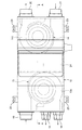
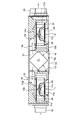
以下、図面に基づいて、本発明の実施の形態について説明する。図1は本発明の実施の形態である換気装置を下面側から見た状態で示す斜視図、図2は図1に示す換気装置の側面図、図3は図1に示す換気装置の底面図、図4は図1に示す換気装置から本体ケーシング底面部分および遠心ファンなどを取り外した状態を示す図、図5は図3のA−A線における断面図である。 Hereinafter, embodiments of the present invention will be described with reference to the drawings. 1 is a perspective view showing a ventilator according to an embodiment of the present invention as viewed from the lower surface side, FIG. 2 is a side view of the ventilator shown in FIG. 1, and FIG. 3 is a bottom view of the ventilator shown in FIG. 4 is a view showing a state in which the bottom portion of the main casing and the centrifugal fan are removed from the ventilation device shown in FIG. 1, and FIG. 5 is a cross-sectional view taken along the line AA of FIG.
図1〜図5に示すように、本実施形態の換気装置10は、直方体形状をした本体ケーシング15と、本体ケーシング15内に収容された本体ユニット16と、本体ユニット16内に配置された二つの遠心ファンユニット11,12と、これらの遠心ファンユニット11,12の間の収納部27に着脱可能に配置された熱交換素子17と、を備えている。本体ケーシング15の一方の端面には複数の室内側吐出口18と、室内側吸込口19が設けられ、他方の端面には室外側吐出口20と室外側吸込口21が設けられている。また、本体ケーシング15のその他の端面には、換気装置10を吊り下げ保持する吊り金具22を係止するためのフック部23が突設されている。
As shown in FIGS. 1 to 5, the
さらに、本体ケーシング15の底面の中央部には、熱交換素子17の交換やメンテナンスなどを行うための開口部15a(図5参照)が開設され、この開口部15aに開閉可能な蓋24が装着されている。詳しくは、図1に示すように、本体ケーシング15の底面の中央部は、複数のネジ15cによって固定された補助底板15bで構成され、この補助底板15bに開設された開口部15aに、蓋24がネジ24aによって開閉可能に装着されている。
Furthermore, an opening 15a (see FIG. 5) for exchanging and maintaining the
本体ケーシング15は換気装置10の外形を構成する箱体状の部材であり、本体ユニット16は本体ケーシング15内に配置された発泡合成樹脂製の部材であり、本体ケーシング15内の空間を区画して、後述する吸込流路13a,14aなどを形成している。遠心ファンユニット11,12は、遠心ファン11a,12aと、これを回転駆動するモータ11b,12bと、を一体化した部材である。遠心ファンユニット11,12は同様の構造、機能を有しているが、以下、給気ファンユニット11および排気ファンユニット12と表示する。
The
給気ファンユニット11および排気ファンユニット12は、それぞれ遠心ファン11a,12aおよびこれらを回転駆動するモータ11b,12bを備え、本体ユニット16に設けられたファンケーシング部13,14内に水平に配置されている。それぞれのファンケーシング部13,14には、遠心ファン11a,12a方向へ空気流を吸い込むために当該遠心ファン11a,12aに臨む位置に開設された吸込口13b,14bと、吸込口13b,14bから吸い込んだ空気流を排出するための排出流路13c,14cと、吸込口13b,14bとそれぞれ連通し遠心ファン11a,12aの回転軸11c,12cと直交する方向から空気流を吸込む吸込流路13a,14aと、が設けられている。
The air
給気ファンユニット11の稼働により、室外側吸込口21から吸い込まれた空気は、ファンケーシング部14側方の給気流路25内へ流れ込み、熱交換素子17を通過した後、吸込流路13aへ流れ込み、ここを通過して吸込口13bへ吸い込まれ、排出流路13cへ排出された後、複数の室内側吐出口18からそれぞれダクト(図示せず)を経由して各室内へ向かって吐出される。
Due to the operation of the air
また、排気ファンユニット12の稼働により、室内側吸込口19から吸い込まれた空気は、ファンケーシング部13側方の排気流路26へ流れ込み、熱交換素子17を通過した後、吸込流路14aへ流れ込み、ここを通過して吸込口14bへ吸い込まれ、排出流路14cへ排出された後、室外側吐出口20から室外へ向かって吐出される。
In addition, due to the operation of the
このように、換気装置10の給気ファンユニット11,排気ファンユニット12を稼働させることによって室内空気の室外への排出と、室外空気の室内への導入という二つの換気作用を得ることができる。また、室内空気および室外空気が熱交換素子17を通過する際に互いの間で熱交換が行われるため、室内の空調効率が低下することもない。
In this way, by operating the air
次に、図6〜図8を参照して、ファンケーシング部13,14の構造、機能などについて詳しく説明する。図6は図2のB−B線における一部省略断面図、図7は図4に示す本体ユニットの一部切欠斜視図、図8は図5の一部拡大図である。なお、ファンケーシング部13,14の吸込口付近は互いにほぼ同じ構造であるため、以下、ファンケーシング部14について説明する。
Next, the structure and function of the
図6〜図8に示すように、吸込流路14a内面においてファンケーシング部14の吸込口14bと対向する部分に、吸込口14bに向かって突出した突状部28と、吸込口14bに向かって傾斜した気流誘導面29とを設けている。また、吸込口14bに臨む領域に空気流を集合させるための気流誘導ガイド30を設けている。突状部28,気流誘導面29および気流誘導ガイド30は、吸込口14bに対向する部分に位置する吸込流路14aと一体的に形成されている。
As shown in FIGS. 6-8, in the inner surface of the
図6に示すように、排気ファンユニット12の稼働により、吸込流路14aに沿って流れてくる空気流は気流誘導ガイド30の働きにより、遠心ファン12aの吸込口14bに臨む領域に集められるため、吸込口14bへスムーズに流れ込むようになり、ファン効率の低下を抑制することができる。
As shown in FIG. 6, due to the operation of the
また、遠心ファン12aの回転軸12cと交差する方向に沿って吸込流路14a内を流れてきた空気流は突状部28の前面に衝突し、衝突した空気流が遠心ファン12aの吸込口14bに誘導されるため、吸込流路14aを薄型化しても、ファン効率が低下することがない。従って、吸込流路14aを薄型化することによって換気装置10全体のコンパクト化を図ることができる。さらに、本実施形態では、吸込口14bの対向部分に向かって流入する空気流が当接する領域である突状部28の前面を凸面部28aとしているため、吸込口14bの対向部分に向かって流入した空気流は凸面部28aに当接して流速が緩和されて、遠心ファン12aの吸込口14bに流れ込むこととなり、ファン効率を向上させることができる。このような効果は、本実施形態のように、吸込流路14a内における空気流の流入方向と、排出流路14c内における空気流の流出方向とがおおむね平行をなす構造を有する換気装置10において顕著である。
In addition, the air flow that has flowed through the
さらに、吸込流路14a内において、吸込口14bと対向する部分には、気流誘導面29が設けられているため、前述した突状部28に衝突せず、その下流側に回り込もうとする空気流は、この気流誘導面29により、遠心ファン12aの吸込口14bに向かうように誘導され、吸込口14bから均一に吸い込まれるため、ファン効率の低下を抑制することができる。
Furthermore, since the
本実施形態では、吸込口14bから見た突状部28の形状を楕円形とするとともに、その基端部から先端部に向かって先細り形状としているため、吸込口14bの対向部分に向かって流入した空気流は、楕円形をした突状部28に当接して流速が緩和され、その基端部から先端部に沿って流動しながら遠心ファン12aの吸込口14bに流れ込むようになるため、ファン効率の向上に有効である。なお、本実施形態では、突状部28の頂上部分に吸込口14bと略平行な平面部28bを設けることにより、突状部28の全体形状を略楕円錐台形状としているが、これに限定するものではない。
In the present embodiment, the shape of the projecting
一方、気流誘導ガイド30の形状は、吸込流路14aの上流から下流に向かって滑らかに縮幅する略放物線形状としているため、吸込流路14a内に沿って流動してきた空気流を気流誘導ガイド30が突状部28、気流誘導面29に向かうように誘導することができる。このため、ファン効率の低下を抑制する上で有効である。なお、本実施形態では、気流誘導面29、気流誘導ガイド30および突状部28を本体ユニット16と一体的に形成しているため、当該換気装置10の製造工程を簡易化することができる。
On the other hand, since the shape of the
次に、図9,図10を参照して、換気装置10における熱交換素子17の着脱方法およびメンテナンスなどについて説明する。図9は図1に示す換気装置の一部分解斜視図、図10は図1に示す換気装置の一部分解断面図である。
Next, with reference to FIG. 9, FIG. 10, the attachment or detachment method of the
メンテナンスや部品交換などを目的として熱交換素子17を取り出したい場合は、図9に示すような手順で行う。即ち、換気装置10の本体ケーシング15底面にあるネジ24aを緩めて蓋24を離脱させると、開口部15a(図5参照。)が現れるので、開口部15aから2枚の遮蔽板32を取り出せば、同様に開口部15aを通して熱交換素子17を取り出すことができる。また、熱交換素子17を取り付ける場合は、前述と逆の手順をとればよい。従って、熱交換素子17の着脱作業は容易である。
When it is desired to take out the
一方、本体ケーシング15内に配置されている給気ファンユニット11を取り出したい場合は、図10に示すような手順で行う。まず、図1で示したように、本体ケーシング15の底面にある複数のネジ15cを緩めると、蓋24とともに補助底板15bが離脱可能となり、これによって、本体ケーシング15の底面中央部分に、開口部15aよりも開口面積の広い開口部15dが現れる。従って、前述と同様、開口部15dから2枚の遮蔽板および熱交換素子17を取り出すことができる。
On the other hand, when it is desired to take out the air
そして、熱交換素子17の取り出しが終わった後、ファンケーシング部13を構成する着脱可能な分割体13dを収納部27方向へ移動させて開口部15dから取り出せば、この後、給気ファンユニット11を開口部15dに臨む位置までスライド移動させ、開口部15dを通して取り出すことができる。同様に、ファンケーシング部14を構成する着脱可能な分割体14dを収納部27方向へ移動させて開口部15aから取り出せば、排気ファンユニット12を開口部15dに臨む位置までスライド移動させて取り出すことができる。
Then, after the
このように、本体ケーシング15底面の複数のネジ15cを緩め、補助底板15bを取り外して開口部15dを開放すれば、開口部15dを通して、熱交換素子17だけでなく給気ファンユニット11,排気ファンユニット12を取り出し可能となるため、これらの給気ファンユニット11,排気ファンユニット12を構成する遠心ファン11a,12aやモータ11b,12bなどが故障したり、メンテナンスが必要となったりしたときの分解作業が容易であり、メンテナンス性に優れている。
In this way, if the plurality of
本発明の換気装置は、建築物に配備される空調設備あるいは換気設備などの一部として広く利用することができる。 The ventilator of the present invention can be widely used as a part of an air conditioner or a ventilator installed in a building.
10 換気装置
11 給気ファンユニット(遠心ファンユニット)
12 排気ファンユニット(遠心ファンユニット)
11a,12a 遠心ファン
11b,12b モータ
11c,12c 回転軸
13,14 ファンケーシング部
13a,14a 吸込流路
13b,14b 吸込口
13c,14c 排出流路
13d,14d 分割体
15 本体ケーシング
15a,15d 開口部
15b 補助底板
15c,24a ネジ
16 本体ユニット
17 熱交換素子
18 室内側吐出口
19 室内側吸込口
20 室外側吐出口
21 室外側吸込口
22 吊り金具
23 フック部
24 蓋
25 給気流路
26 排気流路
27 収納部
28 突状部
28a 凸面部
28b 平面部
29 気流誘導面
30 気流誘導ガイド
32 遮蔽板
10
12 Exhaust fan unit (centrifugal fan unit)
11a,
Claims (8)
Priority Applications (1)
| Application Number | Priority Date | Filing Date | Title |
|---|---|---|---|
| JP2005322612A JP4863696B2 (en) | 2005-11-07 | 2005-11-07 | Ventilation equipment |
Applications Claiming Priority (1)
| Application Number | Priority Date | Filing Date | Title |
|---|---|---|---|
| JP2005322612A JP4863696B2 (en) | 2005-11-07 | 2005-11-07 | Ventilation equipment |
Publications (2)
| Publication Number | Publication Date |
|---|---|
| JP2007127391A JP2007127391A (en) | 2007-05-24 |
| JP4863696B2 true JP4863696B2 (en) | 2012-01-25 |
Family
ID=38150183
Family Applications (1)
| Application Number | Title | Priority Date | Filing Date |
|---|---|---|---|
| JP2005322612A Active JP4863696B2 (en) | 2005-11-07 | 2005-11-07 | Ventilation equipment |
Country Status (1)
| Country | Link |
|---|---|
| JP (1) | JP4863696B2 (en) |
Cited By (1)
| Publication number | Priority date | Publication date | Assignee | Title |
|---|---|---|---|---|
| KR101828337B1 (en) * | 2017-07-03 | 2018-02-13 | 주식회사 에코이엔지 | Noise absorbing device and Air circulator for reducing noise |
Families Citing this family (7)
| Publication number | Priority date | Publication date | Assignee | Title |
|---|---|---|---|---|
| WO2010109662A1 (en) * | 2009-03-27 | 2010-09-30 | 三菱電機株式会社 | Heat exchange ventilation device |
| JP2011075119A (en) * | 2009-09-29 | 2011-04-14 | Sanyo Electric Co Ltd | Outside air treating air conditioner |
| JP5511560B2 (en) * | 2010-07-13 | 2014-06-04 | 三菱電機株式会社 | Heat exchange ventilator |
| JP5538298B2 (en) * | 2011-04-27 | 2014-07-02 | 三菱電機株式会社 | Heat exchange ventilator |
| EP3370002B1 (en) * | 2015-10-29 | 2020-03-11 | Mitsubishi Electric Corporation | Heat exchanging ventilation device |
| TWI614461B (en) * | 2016-01-27 | 2018-02-11 | 台達電子工業股份有限公司 | Total heat exchanger |
| JP6887491B2 (en) * | 2017-12-13 | 2021-06-16 | 三菱電機株式会社 | Blower |
Family Cites Families (7)
| Publication number | Priority date | Publication date | Assignee | Title |
|---|---|---|---|---|
| JPS6082733A (en) * | 1983-10-14 | 1985-05-10 | Hitachi Ltd | Air ventilation device having heat exchanger |
| JPH04309741A (en) * | 1991-04-09 | 1992-11-02 | Mitsubishi Electric Corp | Ventilating device |
| JP2931431B2 (en) * | 1991-04-09 | 1999-08-09 | 三菱電機株式会社 | Ventilation equipment |
| JP3072171B2 (en) * | 1991-12-25 | 2000-07-31 | 日本ノイズコントロール株式会社 | Air flow guide silencer on fan suction side |
| JP3307764B2 (en) * | 1994-03-31 | 2002-07-24 | 東芝キヤリア株式会社 | Air conditioner |
| JP3660954B2 (en) * | 1996-01-23 | 2005-06-15 | ダイキン工業株式会社 | Heat exchange ventilator |
| JPH10267341A (en) * | 1997-03-28 | 1998-10-09 | Matsushita Seiko Co Ltd | Ventilating device |
-
2005
- 2005-11-07 JP JP2005322612A patent/JP4863696B2/en active Active
Cited By (1)
| Publication number | Priority date | Publication date | Assignee | Title |
|---|---|---|---|---|
| KR101828337B1 (en) * | 2017-07-03 | 2018-02-13 | 주식회사 에코이엔지 | Noise absorbing device and Air circulator for reducing noise |
Also Published As
| Publication number | Publication date |
|---|---|
| JP2007127391A (en) | 2007-05-24 |
Similar Documents
| Publication | Publication Date | Title |
|---|---|---|
| JP4863696B2 (en) | Ventilation equipment | |
| JP6022003B2 (en) | Air conditioner indoor unit | |
| JP5030602B2 (en) | Air conditioner | |
| WO2006009047A1 (en) | Air conditioner | |
| JP4052264B2 (en) | Embedded ceiling air conditioner | |
| JP5012260B2 (en) | Duct fan | |
| JP6545293B2 (en) | Indoor unit of air conditioner | |
| US20050287945A1 (en) | Ventilating system | |
| KR20160044998A (en) | Centrifugal fan and Air conditioner having the same | |
| JP6639654B2 (en) | Air conditioner | |
| WO2006013836A1 (en) | Heat exchange type ventilator | |
| JP2005315536A (en) | Air conditioner | |
| JP2005221218A (en) | Air cleaner | |
| KR20190052388A (en) | Air Conditioner | |
| JP2012163255A (en) | Indoor unit of air conditioner | |
| JP2001248853A (en) | Indoor unit for air conditioner | |
| JP2014092333A (en) | Heat exchange ventilation device | |
| WO2017134744A1 (en) | Indoor unit for air conditioners | |
| KR100698910B1 (en) | Duct type air conditioner | |
| JP2017215091A (en) | Indoor machine of air conditioner | |
| KR20080062890A (en) | Airconditioner | |
| CN108474582B (en) | Air conditioning system | |
| KR20040015872A (en) | An air-conditioner | |
| JP2002022233A (en) | Air conditioning apparatus | |
| JP2006132884A (en) | Ventilating device |
Legal Events
| Date | Code | Title | Description |
|---|---|---|---|
| A621 | Written request for application examination |
Free format text: JAPANESE INTERMEDIATE CODE: A621 Effective date: 20081007 |
|
| A977 | Report on retrieval |
Free format text: JAPANESE INTERMEDIATE CODE: A971007 Effective date: 20110210 |
|
| A131 | Notification of reasons for refusal |
Free format text: JAPANESE INTERMEDIATE CODE: A131 Effective date: 20110222 |
|
| A521 | Written amendment |
Free format text: JAPANESE INTERMEDIATE CODE: A523 Effective date: 20110421 |
|
| TRDD | Decision of grant or rejection written | ||
| A01 | Written decision to grant a patent or to grant a registration (utility model) |
Free format text: JAPANESE INTERMEDIATE CODE: A01 Effective date: 20111025 |
|
| A01 | Written decision to grant a patent or to grant a registration (utility model) |
Free format text: JAPANESE INTERMEDIATE CODE: A01 |
|
| A61 | First payment of annual fees (during grant procedure) |
Free format text: JAPANESE INTERMEDIATE CODE: A61 Effective date: 20111108 |
|
| FPAY | Renewal fee payment (event date is renewal date of database) |
Free format text: PAYMENT UNTIL: 20141118 Year of fee payment: 3 |
|
| R150 | Certificate of patent or registration of utility model |
Ref document number: 4863696 Country of ref document: JP Free format text: JAPANESE INTERMEDIATE CODE: R150 Free format text: JAPANESE INTERMEDIATE CODE: R150 |
|
| R250 | Receipt of annual fees |
Free format text: JAPANESE INTERMEDIATE CODE: R250 |
|
| S531 | Written request for registration of change of domicile |
Free format text: JAPANESE INTERMEDIATE CODE: R313532 |
|
| R350 | Written notification of registration of transfer |
Free format text: JAPANESE INTERMEDIATE CODE: R350 |