JP4863348B2 - Plowing depth control device - Google Patents
Plowing depth control device Download PDFInfo
- Publication number
- JP4863348B2 JP4863348B2 JP2005323455A JP2005323455A JP4863348B2 JP 4863348 B2 JP4863348 B2 JP 4863348B2 JP 2005323455 A JP2005323455 A JP 2005323455A JP 2005323455 A JP2005323455 A JP 2005323455A JP 4863348 B2 JP4863348 B2 JP 4863348B2
- Authority
- JP
- Japan
- Prior art keywords
- deviation
- tilling
- control
- magnitude
- automatic
- Prior art date
- Legal status (The legal status is an assumption and is not a legal conclusion. Google has not performed a legal analysis and makes no representation as to the accuracy of the status listed.)
- Expired - Fee Related
Links
Images


Landscapes
- Lifting Devices For Agricultural Implements (AREA)
Description
本発明は、トラクタ等の車輌本体に対して昇降可能に連結された耕耘機の耕深深さを制御するための耕深制御装置に関する。 The present invention relates to a tilling depth control device for controlling a tilling depth of a tiller connected to a vehicle body such as a tractor so as to be movable up and down.
トラクタ等の車輌本体に対して昇降可能に連結された耕耘機の自動耕深制御を行う耕深制御装置として、例えば、前記耕耘機を前記車輌本体に対して昇降させる昇降用アクチュエータと、前記耕耘機の耕深深さを設定する耕深深さ設定手段と、前記耕耘機の耕耘位置を検出する耕耘位置検出手段と、前記昇降用アクチュエータを作動させる制御手段とを備えた耕深制御装置が知られている(例えば、下記特許文献1参照)。
As a tilling depth control device that performs automatic tilling control of a tiller that is connected to a vehicle body such as a tractor so as to be able to move up and down, for example, a lifting actuator that lifts and lowers the tiller with respect to the vehicle body, and the tillage A tilling depth control device comprising a tilling depth setting means for setting a tilling depth of the machine, a tilling position detecting means for detecting a tilling position of the tiller, and a control means for operating the lifting actuator. It is known (for example, refer to
詳しくは、前記耕耘機は、耕耘爪軸と、該耕耘爪軸に設けられた耕耘爪と、該耕耘爪の回転軌跡の上方を覆う耕耘上面カバーと、該耕耘上面カバーの後端部に揺動可能に連結された耕耘リヤカバーとを有している。
前記耕深深さ設定手段は、設定耕深位置(目標耕深位置)として、前記耕耘上面カバーに対する前記耕耘リヤカバーの回動角度を設定し、一方、前記耕深位置検出手段は、実耕深位置(検出耕深位置)として、前記耕耘上面カバーに対する前記耕耘リヤカバーの回動角度を検出している。
そして、前記制御手段は、前記検出耕深位置と前記設定耕深位置との偏差に基づいて、前記昇降用アクチュエータの制御条件を算出し、該制御条件に基づき前記検出耕深位置が前記設定耕深位置と一致するように前記昇降用アクチュエータを作動させることで、自動耕深制御を行っている。
Specifically, the cultivator includes a cultivating claw shaft, a cultivating claw provided on the cultivating claw shaft, a cultivating top cover that covers the rotation trajectory of the cultivating claw, and a rear end of the cultivating top cover. A tillable rear cover movably coupled thereto;
The tilling depth setting means sets a rotation angle of the tilling rear cover with respect to the tilling upper surface cover as a set tilling position (target tilling position), while the tilling position detecting means has an actual tilling depth As the position (detected tilling depth position), the rotation angle of the tilling rear cover with respect to the tilling top cover is detected.
Then, the control means calculates a control condition for the lifting actuator based on a deviation between the detected tilling position and the set tilling position, and the detected tilling position is calculated based on the control condition. Automatic tilling control is performed by operating the lifting actuator so as to coincide with the deep position.
ところで、従来の耕深制御装置においては、前記検出耕深位置と前記設定耕深位置との偏差の大きさに拘わらず、前記自動耕深制御における制御条件が一定とされていた為、枕地等の凹凸の多い場所を耕耘作業する際等のように前記偏差の大きさが変動する場合に制御が不安定となり、場合によっては、ハンチング現象が発生するという問題があった。 By the way, in the conventional plowing depth control device, the control condition in the automatic plowing depth control is constant regardless of the magnitude of the deviation between the detected plowing depth position and the set plowing depth position. There is a problem that the control becomes unstable when the magnitude of the deviation fluctuates, such as when plowing a place with many irregularities, such as a hunting phenomenon.
即ち、前記耕深制御装置においては、前記耕耘機の昇降動に伴う前記耕耘位置検出手段の検出感度変化による悪影響を補償する為に、前記偏差に基づく制御信号に制御ゲインを乗算して前記昇降用アクチュエータへ出力することが提案されている。
これに代えて、若しくは、加えて、前記偏差に対する不感帯幅を設けることや、前記検出耕深位置の入力経路及び/又は前記昇降用アクチュエータへの出力経路にフィルタを介挿させることも提案されている。
That is, in the tilling depth control device, in order to compensate for an adverse effect due to a change in detection sensitivity of the tillage position detecting means associated with the up and down movement of the tiller, the control signal based on the deviation is multiplied by a control gain and the lifting and lowering is performed. It has been proposed to output to an actuator.
Alternatively or in addition, it has also been proposed to provide a dead band width for the deviation, or to insert a filter in the input path of the detection depth position and / or the output path to the lifting actuator. Yes.
しかしながら、従来の耕深制御装置においては、前記制御ゲイン、前記不感帯幅及び前記フィルタによって遮断される周波数の範囲を含む前記制御条件が、前記偏差の大小に拘わらず一定とされていた。
従って、例えば、前記制御条件が、前記制御ゲイン「大」、前記不感帯幅「小」及び遮断周波数の範囲「大」に設定されていると、前記偏差が大きい場合に前記耕耘機の昇降量が過大になり、制御の不安定化が生じる。
However, in the conventional tilling depth control device, the control condition including the control gain, the dead band width, and the frequency range cut off by the filter is constant regardless of the magnitude of the deviation.
Therefore, for example, when the control condition is set to the control gain “large”, the dead band width “small”, and the cutoff frequency range “large”, the lift amount of the tiller is increased when the deviation is large. It becomes excessive and instability of control occurs.
又、前記従来の耕深制御装置においては、前記偏差の検出毎に前記昇降用アクチュエータを作動制御している。
従って、前輪が坂にさしかかった際や凹凸の多い場所を耕耘する際のように持続的な外乱の入力がある場合に、制御の不安定化を招き、ハンチング現象が生じやすいという問題があった。
Therefore, when there is a continuous disturbance input, such as when the front wheel approaches a slope or when plowing a place with a lot of unevenness, there is a problem that hunting phenomenon is likely to occur due to instability of control. .
本発明は、前記従来技術に鑑みなされたものであり、検出耕深位置と設定耕深位置との偏差の大小に拘わらず、耕耘機の昇降制御の安定化を図り得る構造簡単な耕深制御装置の提供を、一の目的とする。
又、本発明は、持続的な外乱の入力があった場合であっても、耕耘機の昇降制御の安定化を図り得る構造簡単な耕深制御装置の提供を、他の目的とする。
The present invention has been made in view of the above-described prior art, and has a structure with simple plowing depth control that can stabilize the lifting control of the tiller regardless of the deviation between the detected plowing depth position and the set plowing depth position. One object is to provide an apparatus.
Another object of the present invention is to provide a tilling depth control device having a simple structure that can stabilize the lifting control of the tiller even when a continuous disturbance is input.
本発明は、前記課題を解決するために、次の第1から第3態様の耕深制御装置を提供する。
(1)第1態様の耕深制御装置
リヤカバーの回動角度に基づき、車輌本体に対して昇降可能に連結された耕耘機の検出耕深位置を設定耕深位置に追従させる自動耕深制御を行うように構成された耕深制御装置であって、前記検出耕深位置と前記設定耕深位置との偏差の変化割合の大きさに基づき自動耕深制御における制御ゲインを変更するように構成したことを特徴とする耕深制御装置。
(2)第2態様の耕深制御装置
リヤカバーの回動角度に基づき、車輌本体に対して昇降可能に連結された耕耘機の検出耕深位置を設定耕深位置に追従させる自動耕深制御を行うように構成された耕深制御装置であって、前記検出耕深位置と前記設定耕深位置との偏差の変化割合の大きさに基づき自動耕深制御における不感帯幅を変更するように構成したことを特徴とする耕深制御装置。
(3)第3態様の耕深制御装置
リヤカバーの回動角度に基づき、車輌本体に対して昇降可能に連結された耕耘機の検出耕深位置を設定耕深位置に追従させる自動耕深制御を行うように構成された耕深制御装置であって、前記検出耕深位置と前記設定耕深位置との偏差の変化割合の大きさに基づき自動耕深制御におけるフィルタリング条件を変更するように構成したことを特徴とする耕深制御装置。
The present invention, in order to solve the previous SL problems, provides a tilling depth control device of the third embodiment from the first of the following.
( 1 ) Plowing depth control device according to the first aspect Based on the rotation angle of the rear cover, automatic plowing depth control is performed so that the detected plowing depth position of a cultivator coupled to the vehicle body so as to be movable up and down follows the set plowing depth position. A plowing depth control device configured to perform the plowing depth control device, wherein the control gain in the automatic plowing depth control is changed based on a magnitude of a change rate of deviation between the detected plowing depth position and the set plowing depth position. A plowing depth control device characterized by that.
( 2 ) Plowing depth control device of the second mode Automatic plowing depth control is performed based on the rotation angle of the rear cover so that the detection plowing position of a cultivator coupled to the vehicle body so as to be movable up and down follows the set plowing depth position. A plowing depth control device configured to perform, and configured to change a dead zone width in automatic plowing depth control based on a magnitude of a change rate of deviation between the detected plowing depth position and the set plowing depth position A plowing depth control device characterized by that.
( 3 ) Plowing depth control device according to the third aspect Based on the rotation angle of the rear cover, automatic plowing depth control is performed to make the detected plowing depth position of the cultivator coupled to the vehicle body so as to be movable up and down follow the set plowing depth position. A plowing depth control device configured to perform, and configured to change a filtering condition in automatic plowing depth control based on a magnitude of a change rate of deviation between the detected plowing depth position and the set plowing depth position A plowing depth control device characterized by that.
前記第1から第3態様の耕深制御装置において、前記偏差の変化割合の大きさとしては、代表的には、所定時間内(又は所定サンプリング数)における平均値を例示できる。ここで、前記平均値は、単純平均値、重みつき平均値、単純移動平均値、重みつき移動平均値等を含む概念である。また、前記平均値の概念と同様の観点から、前記偏差の大きさは、所定時間内(又は所定サンプリング数)における積分値であってもよい。 In the plowing depth control device according to the first to third aspects, the magnitude of the change ratio of the deviation can typically be exemplified by an average value within a predetermined time (or a predetermined number of samplings). Here, the average value is a concept including a simple average value, a weighted average value, a simple moving average value, a weighted moving average value, and the like. Further, from the same viewpoint as the concept of the average value, the magnitude of the deviation may be an integrated value within a predetermined time (or a predetermined sampling number).
また、本発明に係る第3態様の耕深制御装置において、前記フィルタリング条件としては、代表的には、前記検出耕深位置の入力経路及び/又は前記耕耘機を前記車輌本体に対して昇降させる昇降用アクチュエータへの出力経路に介挿されるフィルタの遮断周波数の範囲を例示できる。 Moreover, in the tilling depth control apparatus according to the third aspect of the present invention, as the filtering condition, typically, the input path of the detected tilling position and / or the tiller is moved up and down with respect to the vehicle body. The range of the cut-off frequency of the filter inserted in the output path to the lift actuator can be exemplified.
本発明の第1態様に係る耕深制御装置によれば、前記検出耕深位置と前記設定耕深位置との偏差の変化割合の大きさに基づき、自動耕深制御における制御ゲインを変更するように構成したので、前記偏差の大小に拘わらず自動耕深制御の安定化を図ることができる。
例えば、前記偏差の変化割合の大きさが大きくなるに従って前記制御ゲインを小さくすることができる。
これに代えて、前記偏差の変化割合の大きさが所定の閾値以内の場合には前記制御ゲインを所定の制御ゲインと等しいか又は前記所定制御ゲインより大きくし、且つ、前記偏差の変化割合の大きさが所定の閾値よりも大きい場合には前記制御ゲインを前記所定制御ゲインより小さくすることもできる。
これらの構成によれば、前記偏差が大きい場合におけるオーバーシュート現象を有効に防止しつつ、可及的速やかに耕深位置を設定耕深位置に追従させることができ、これにより、自動耕深制御の安定化を図ることができる。
According to the tilling depth control device according to the first aspect of the present invention, the control gain in the automatic tilling depth control is changed based on the magnitude of the change rate of the deviation between the detected tilling position and the set tilling position. Therefore, it is possible to stabilize the automatic tilling depth control regardless of the magnitude of the deviation.
For example, the control gain can be reduced as the change rate of the deviation increases.
Instead, if the magnitude of the deviation change rate is within a predetermined threshold, the control gain is equal to or greater than the predetermined control gain, and the deviation change rate When the magnitude is larger than a predetermined threshold, the control gain can be made smaller than the predetermined control gain.
According to these configurations, the plowing depth position can be made to follow the set plowing depth position as quickly as possible while effectively preventing the overshoot phenomenon when the deviation is large, thereby enabling automatic plowing depth control. Can be stabilized.
本発明の第2態様に係る耕深制御装置によれば、前記検出耕深位置と前記設定耕深位置との偏差の変化割合の大きさに基づき、自動耕深制御における不感帯幅を変更するように構成したので、前記偏差の変化割合の大小に拘わらず自動耕深制御の安定化を図ることができる。
例えば、前記偏差の変化割合の大きさが大きくなるに従って前記不感帯幅を大きくすることができる。
これに代えて、前記偏差の変化割合の大きさが所定の閾値以内の場合には前記不感帯幅を所定の不感帯幅と等しいか又は前記所定不感帯幅より小さくし、且つ、前記偏差の変化割合の大きさが所定の閾値よりも大きい場合には前記不感帯幅を前記所定不感帯幅より大きくすることもできる。
これらの構成によれば、前記偏差が大きい場合におけるオーバーシュート現象を有効に防止しつつ、可及的速やかに耕深位置を設定耕深位置に追従させることができ、これにより、自動耕深制御の安定化を図ることができる。
According to the tilling depth control apparatus according to the second aspect of the present invention, the dead zone width in the automatic tilling depth control is changed based on the magnitude of the change rate of the deviation between the detected tilling position and the set tilling position. Therefore, it is possible to stabilize the automatic tilling control regardless of the variation rate of the deviation.
For example, the dead zone width can be increased as the deviation change rate increases.
Instead, if the magnitude of the change rate of the deviation is within a predetermined threshold, the dead zone width is equal to or smaller than the predetermined dead zone width, and the deviation change rate When the size is larger than a predetermined threshold, the dead zone width can be made larger than the predetermined dead zone width.
According to these configurations, the plowing depth position can be made to follow the set plowing depth position as quickly as possible while effectively preventing the overshoot phenomenon when the deviation is large, thereby enabling automatic plowing depth control. Can be stabilized.
本発明の第3態様に係る耕深制御装置によれば、前記検出耕深位置と前記設定耕深位置との偏差の変化割合の大きさに基づき、自動耕深制御におけるフィルタリング条件を変更するように構成したので、前記偏差の大小に拘わらず自動耕深制御の安定化を図ることができる。
即ち、制御手段への検出耕深位置の入力経路及び/又は制御手段から昇降用アクチュエータへの出力経路に介挿されるフィルタによって遮断される周波数範囲(遮断周波数範囲)を、前記偏差の変化割合の大きさに基づいて変更することで、該偏差の大小に拘わらず自動耕深制御の安定化を図ることができる。
According to the tilling depth control apparatus according to the third aspect of the present invention, the filtering condition in the automatic tilling depth control is changed based on the magnitude of the change ratio of the deviation between the detected tilling position and the set tilling position. Therefore, it is possible to stabilize the automatic tilling depth control regardless of the magnitude of the deviation.
That is, a frequency range (cutoff frequency range) cut off by a filter inserted in the input path of the detected plowing depth position to the control means and / or the output path from the control means to the lifting / lowering actuator is set as the change rate of the deviation. By changing based on the size, it is possible to stabilize automatic tilling control regardless of the magnitude of the deviation.
例えば、前記偏差の変化割合の大きさが所定の閾値以内の場合には前記遮断周波数範囲を所定の遮断周波数範囲と等しいか又は前記所定遮断周波数範囲より大きくし、且つ、前記偏差の変化割合の大きさが所定の閾値よりも大きい場合には前記遮断周波数範囲を前記所定遮断周波数範囲より小さくすれば、前記偏差が小さい場合におけるオーバーシュート現象を防止しつつ、前記偏差が大きい場合における振動的動作を可及的速やかに収束させることができる。
これに代えて、前記偏差の変化割合が大きくなるに従って前記遮断周波数範囲を小さくしてもよい。この場合においても、前記偏差が小さい場合におけるオーバーシュート現象を防止しつつ、前記偏差が大きい場合における振動的動作を可及的速やかに収束させることができる。
For example, when the deviation change rate is within a predetermined threshold, the cutoff frequency range is equal to or larger than the predetermined cutoff frequency range, and the deviation change rate is When the magnitude is larger than a predetermined threshold, if the cut-off frequency range is made smaller than the predetermined cut-off frequency range, an overshoot phenomenon in the case where the deviation is small is prevented, and an oscillating operation in the case where the deviation is large. Can be converged as quickly as possible.
Alternatively, the cutoff frequency range may be reduced as the deviation change rate increases. Even in this case, it is possible to converge the vibrational operation when the deviation is large as quickly as possible while preventing the overshoot phenomenon when the deviation is small.
また、本発明の第1から第3態様に係る耕深制御装置において、前記偏差の変化割合の大きさが、所定時間内における平均値又は積分値である場合には、持続的な外乱の入力があった場合であっても、耕耘機の昇降制御の安定化を図ることができる。 Moreover, in the tilling depth control apparatus according to the first to third aspects of the present invention, when the magnitude of the change rate of the deviation is an average value or an integral value within a predetermined time, an input of continuous disturbance Even if there is, stabilization of the raising / lowering control of the tiller can be achieved.
以下、本発明の実施の形態について図面を参照しながら説明する。
図1は本実施の形態に係る耕深制御装置が適用される作業車輌の一例である農作業用トラクタの概略側面図である。図2は図1に示すトラクタの概略平面図である。図3は図1に示すトラクタにおける耕耘機用昇降機構の概略側面図である。図4は図3に示す耕耘機用昇降機構の概略平面図である。図5はロータリー耕耘機の図2におけるV−V線に沿った概略断面図である。図6は該ロータリー耕耘機の概略背面図である。図7は該トラクタの油圧回路図である。
Hereinafter, embodiments of the present invention will be described with reference to the drawings.
FIG. 1 is a schematic side view of a farm tractor which is an example of a working vehicle to which a plowing depth control apparatus according to the present embodiment is applied. FIG. 2 is a schematic plan view of the tractor shown in FIG. FIG. 3 is a schematic side view of the tiller lifting mechanism in the tractor shown in FIG. 4 is a schematic plan view of the tiller lifting mechanism shown in FIG. FIG. 5 is a schematic cross-sectional view of the rotary cultivator along line VV in FIG. FIG. 6 is a schematic rear view of the rotary cultivator. FIG. 7 is a hydraulic circuit diagram of the tractor.
図1乃至図4に示す如く、作業車輌としてのトラクタ100は、車輌本体50と、該車輌本体50の後部に連結されたロータリー耕耘機400とを備えている。
前記車輌本体50は、走行機体1と、該走行機体1を支持する左右一対の前車輪2及び左右一対の後車輪3と、該走行機体1の前部に搭載されたエンジン4とを備えており、前記エンジン4からの動力によって前記後車輪3及び前記前車輪2を作動的に駆動することにより、前後進走行するように構成されている。なお、図中の符号5は前記エンジン4を覆うボンネット5である。
さらに、前記トラクタ100は、前記走行機体1の上面に設けられたキャビン6を有している。該キャビン6の内部には、操縦座席7と、かじ取りすることによって前記前車輪2の操向方向を左右に動かすように構成された操縦ハンドル(丸ハンドル)8とが設置されている。前記キャビン6の外側部には、作業者が乗降するステップ9が設けられ、該ステップ9より内側で且つ該キャビン6の底部より下側には、前記エンジン4に燃料を供給する燃料タンク10が設けられている。
As shown in FIGS. 1 to 4, the
The
Further, the
図1乃至図4に示すように、前記走行機体1は、前バンパ11及び前車軸ケース12を有するエンジンフレーム13と、該エンジンフレーム13の後部にボルトにて着脱自在に固定される左右の機体フレーム15とを有している。
前記機体フレーム15の後部には、前記エンジン4の回転を適宜変速してそれぞれ後輪軸3a及び前輪軸2aを介して前記後車輪3及び前記前車輪2に伝達するためのミッションケース16が連結されている。前記後車輪3は、前記ミッションケース16の外側面から外向きに突出するように装着された後車軸ケース17を介して取付けられている。
なお、前記ミッションケース16の後端面には、前記ロータリー耕耘機400の駆動力を出力する為のPTO軸18が後向きに突出するように設けられている。
As shown in FIGS. 1 to 4, the traveling
A
A
前記ロータリー耕耘機400は、前記ミッションケース16の後部に、一対の左右ロワーリンク311,312及びトップリンク320からなる3点リンク機構300を介して連結される。
図1及び図3に示すように、前記左右ロワーリンク311,312は、前端側が前記ミッションケース16後部の左右側面のそれぞれにロワーリンクピン313を介して回動可能に連結され、且つ、後端側が前記ロータリー耕耘機400における下リンクフレーム440の前端部に下ヒッチピン314を介して連結されている。
前記トップリンク320は、前端側が下記作業機用昇降機構200の後部のトップリンクヒッチ210にトップリンクピン211を介して連結され、且つ、後端側が下記上リンクフレーム410の前端側に上ヒッチピン321を介して連結されている。
The
As shown in FIGS. 1 and 3, the left and right
The
図3及び図4に示すように、前記ミッションケース16の後部上面には、前記ロータリー耕耘機400を昇降動する為の油圧式作業機用昇降機構200が着脱可能に取付けられている。
図3及び図4及び図7に示すように、油圧式の作業機用昇降機構200は、昇降用アクチュエータとして作用する単動形の昇降制御油圧シリンダ220と、該油圧シリンダ220におけるピストンによって作動的に回動される左右一対のリフトアーム221,222とを有している。
As shown in FIGS. 3 and 4, a hydraulic working
As shown in FIGS. 3, 4, and 7, the hydraulic working
進行方向に向かって左側の前記リフトアーム221は、左リフトロッド231を介して対応する左側の前記ロワーリンク311に連結されている。
進行方向に向かって右側の前記リフトアーム222は、右リフトロッド232を介して対応する右側の前記ロワーリンク312に連結されている。
つまり、前記昇降制御油圧シリンダ220によって前記左右一対のリフトアーム221,222が車輌左右方向に沿った前記回動軸回りに揺動することで、前記ロータリー耕耘機400は、前記トップリンク320及び前記一対のロワーリンク311,312の前端部回りに昇降するようになっている。
The
The
That is, the lift control
前記右リフトロッド232には、前記ロータリー耕耘機400を前記車輌本体50に対して傾動させる傾動用アクチュエータとして作用する複動形の傾斜制御油圧シリンダ240が介挿されている。
つまり、前記傾斜制御油圧シリンダ240のピストンロッド241が進退することによって、前記ロータリー耕耘機440は、前記左右一対のリフトロッド231,232の他方(ここでは、左リフトロッド231)と該他方のリフトロッド231に対応したロワーリンク311との連結点(即ち、前記ロータリー耕耘機400の左右方向中心位置Dから一方側へ変位された位置)を支点Q(図2参照)として、傾動するようになっている。
A double-acting tilt control
That is, as the
図1、図2、図5及び図6に示すように、前記ロータリー耕耘機400は、横長筒状のメインビーム420と、前記メインビーム420の左右側端部にそれぞれ上端側が連結されたチェーンケース431及び軸受板432と、前記チェーンケース431及び前記軸受板432の下端側に左右両端部が回転自在に軸支された耕耘爪軸433と、前記耕耘爪軸433に放射状にて着脱可能に取り付けられた複数の耕耘爪434と、前記耕耘爪434の回転軌跡の上方を覆うように配置された耕耘上面カバー435と、前記耕耘爪434の回転軌跡の左右側方を覆うように配置された左右耕耘サイドカバー436と、前記耕耘爪434の回転軌跡の後方を覆うように配置された耕耘リヤカバー437と、前記メインビーム420に前端側が取付けられて後方に長く伸びる耕深調節フレーム438と、前記メインビーム420に回動可能に連結された前記上リンクフレーム410と、前記メインビーム420に一体的に連結された前記下リンクフレーム440と、前記上リンクフレーム410の後端側と前記耕深調節フレーム438の前後方向の中間部とをつなぐ伸縮調節可能な耕深調節軸439とを備えている。
As shown in FIGS. 1, 2, 5, and 6, the
詳しくは、前記トップリンク320は、ターンバックル320aの回転にて伸縮されて、該トップリンク320の長さを変更調節可能となるように構成されている(図3及び図4参照)。前記上リンクフレーム410は、前後方向の中間部において、耕深調節支点軸411を介して前記メインビーム420に回動可能に連結されている(図1参照)。そして、前記耕深調節フレーム438は、前端側が前記メインビーム420に一体的に連結されている。
斯かる構成を備えることにより、耕深調節ハンドル439a(図1参照)を回転操作して前記耕深調節軸439を伸縮させると、前記左右一対のロワーリンク311,312及びトップリンク320にて支持される前記ロータリー耕耘機400は、前傾又は後傾姿勢に変化するようになっており、これにより、前記耕耘爪434による耕深位置hD(耕耘深さ)が手動で変更できるように構成されている。
Specifically, the
By providing such a configuration, when the tilling
図1、図5及び図6に示すように、前記メインビーム420の左右中央部には、前記PTO軸18からの駆動力を入力するためのギヤケース450が配置されている。前記PTO軸18と前記ギヤケース450前面側のPTO入力軸451とは、両端に自在継手が備えられた伸縮自在な伝動軸452を介して連結されている。
前記PTO軸18からの動力は、前記ギヤケース450に内蔵されたベベルギヤ(図示せず)、前記メインビーム420に内蔵された回転軸(図示せず)、前記チェーンケース431に内蔵されたスプロケット及びチェーン(図示せず)等を介して前記耕耘爪軸433に伝達される。これにより、前記耕耘爪434が図1及び図5において反時計方向に回転される。
As shown in FIGS. 1, 5, and 6, a
The power from the
図5及び図6に示すように、前記耕耘上面カバー435の後端側には、車輌左右方向に沿った枢着軸437aを介して前記耕耘リヤカバー437が回動可能に連結されている。
さらに、前記耕耘上面カバー435の上面後部には、後方且つ上方へ延びる左右一対のハンガーフレーム441が立設されている。
そして、前記耕耘リヤカバー437の上面後端側と前記左右ハンガーフレーム441の後端側との間には左右一対のハンガー機構460が設けられており、前記耕耘リヤカバー437は、該ハンガー機構460によって、前記枢着軸437a回りに上下動し得るようになっている。
As shown in FIGS. 5 and 6, the tilling
Further, a pair of left and right hanger frames 441 extending rearward and upward are provided upright on the rear upper surface of the tilling
A pair of left and
詳しくは、前記各ハンガーフレーム441の後端部には、車輌左右方向に沿った軸線回り回動自在とされた受圧軸体442が配置されている。該受圧軸体442には、軸線と直交する方向に貫通孔が設けられている。
前記各ハンガー機構460は、前記受圧軸体442の前記貫通孔に摺動可能に挿通された細長い丸棒形のハンガーロッド461を有している。
前記ハンガーロッド461は、下端部が、車輌左右方向に沿った支軸461aを介して、前記耕耘リヤカバー437の後部上面に設けられたブラケット462に回動自在に連結されている(図5参照)。
前記ハンガーロッド461には、前記受圧軸体442より上方側において固設された下降規制ピン461bと、前記下降規制ピン461bと前記受圧軸体442との間に位置するように該ハンガーロッド461に軸線方向摺動可能に外挿された下降規制板463と、該ハンガーロッド461の下方側で且つ前記支軸461aより上方側において固設された上昇規制ピン461cと、前記上昇規制ピン461cによって下方への移動が規制された状態で該ハンガーロッド461に軸線方向摺動可能に外挿された下座板465と、前記下座板465及び前記受圧軸体442の間に位置するように該ハンガーロッド461に外挿された鎮圧用圧縮バネ466と、該鎮圧用圧縮バネ466の上端部と係合する上座板464とが設けられている。
Specifically, a pressure receiving
Each
The
The
斯かるハンガー機構460を備えた前記ロータリー耕耘機400は以下のように作動する。
即ち、前記昇降用アクチュエータによって前記ロータリー耕耘機400が地面Gから離れるように持上げられると、前記耕耘リヤカバー437の後端側が前記枢着軸437a回りに下方側に回動する。
この際、前記ハンガーロッド461は前記受圧軸体442に案内された状態で下方側へ移動するが、前記下降規制ピン461bが前記下降規制板463に当接し且つ該下降規制板463が前記受圧軸体442に当接することで、該ハンガーロッド461の下方側への移動が停止される。従って、前記耕耘リヤカバー437はその後端側を最下降させた姿勢に維持される。
The
That is, when the
At this time, the
一方、前記ロータリー耕耘機400が耕地上面に降ろされて前記耕耘爪434が着地しているときや耕耘作業中においては、前記耕耘リヤカバー437の後端側が、耕耘された耕土との接地圧にて前記枢着軸437a回りに上方に回動することになる。
この際、前記ハンガーロッド461は前記受圧軸体442に案内された状態で上方側へ移動する。斯かるハンガーロッド461の上方側への移動によって、前記上昇規制ピン461c及び前記下座板465を介して前記鎮圧用圧縮バネ466が圧縮される。
即ち、前記耕耘リヤカバー437が前記枢着軸437a回りに上方側へ回動する際には、該耕耘リヤカバー437は前記鎮圧用圧縮バネ466の付勢力に抗して動作することになり、従って、前記耕耘リヤカバー437の後方への土の飛散を有効に防止しつつ、該耕耘リヤカバーによる均平作用を有効に維持することができる。
On the other hand, when the
At this time, the
That is, when the tilling
前記トラクタ100は、さらに、昇降用アクチュエータとして作用する前記昇降制御油圧シリンダ220及び傾動用アクチュエータとして前記昇降制御油圧シリンダ220への作動油給排を行う油圧回路500を備えている。
図7に示すように、前記油圧回路500は、前記エンジン4によって作動的に回転駆動される作業機用油圧ポンプ501と、該油圧ポンプ501の吐出側に流体接続された分流弁505と、該分流弁505によって分岐された一方側油路及び他方側油路にそれぞれ配置された昇降制御用バルブ及び傾斜制御用バルブとを備えている。
本実施の形態においては、前記昇降制御用バルブは、上昇制御電磁弁502及び下降制御電磁弁503を有している。また、前記傾斜制御用バルブは、傾斜制御電磁弁504を有している。
なお、前記油圧回路500は、図7に示すように、リリーフ弁や流量調整弁、チェック弁、オイルクーラ、オイルフィルタ等も備えている。
The
As shown in FIG. 7, the
In the present embodiment, the lift control valve has a lift
As shown in FIG. 7, the
次に、前記キャビン6内に配置された各種操作手段の構成について説明する。
図1及び図2に示すように、前記操縦ハンドル8は、前記操縦座席7の前方に位置する操縦コラム19上に設けられている。
前記キャビン6内には、前記操縦座席7,前記操縦ハンドル8及び前記操縦コラム19に加えて、前記エンジン4の回転数(出力)を調節するためのスロットルレバー617と、前記走行機体1を制動操作するための左右ブレーキペダル20と、前記エンジンから前記前車輪2及び前記後車輪3への動力伝達の係脱操作を行う為のクラッチペダル21と、車輌本体50の走行速度を変速操作する為の走行変速レバー24と、前記エンジン4から前記後車輪3への動力伝達経路に介挿されるディファレンシャル機構をロック操作する為のデフロックペダル25と、前記PTO軸18からの出力回転数を変速操作する為のPTO変速レバー23とが配置されている。
Next, the structure of the various operation means arrange | positioned in the said
As shown in FIGS. 1 and 2, the steering handle 8 is provided on a
In the
さらに、前記キャビン6内には、作業機昇降レバー22,傾斜設定器623及び耕深設定器626が配置されている。
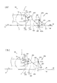
図8に、前記ロータリー耕耘機400の模式側面図を示す。なお、図8(a)は自動耕深制御時のロータリー耕耘機400の昇降状態を示しており、図8(b)は自動高さ制御時のロータリー耕耘機400の昇降状態を示している。
前記作業機昇降レバー22は、前記ロータリー耕耘機400の設定高さ位置(目標高さ位置)hS(図8(b)参照)を手動で変更操作するための上下位置操作手段として作用する。
前記上下位置操作手段は、前記設定高さ位置として、前記リフトアーム221,222の設定リフト角度(目標リフト角度)θS(図8(b)参照)を設定し得るように構成される。
図9に、前記ロータリー耕耘機400の模式背面図を示す。
前記傾斜設定器623は、前記ロータリー耕耘機400の傾斜状態tSを設定する傾斜設定手段として作用する。具体的には、図9に示すように、前記車輌本体50に対する前記ロータリー耕耘機400の左右方向に関する相対的な設定左右傾斜角度(目標左右傾斜角度)φsを予め設定する為のものであり、例えば、可変抵抗器を含み得る。
前記耕深設定器626は、前記ロータリー耕耘機400における耕耘爪434の設定耕深位置(目標耕深位置)hR(図8(a)参照)を設定する耕深深さ設定手段として作用する。
詳細は後述するが、前記ロータリー耕耘機400の耕深位置は、前記耕耘上面カバー435に対する前記耕耘リヤカバー437の回動角度に基づいて制御されるようになっている。従って、前記耕深深さ設定手段は、前記設定耕深位置として、前記耕耘上面カバー435に対する前記耕耘リヤカバー437の設定回動角度(目標回動角度)θR(図8(a)参照)を設定し得るように構成され、例えば、可変抵抗器を含み得る。なお、前記設定回動角度θRは、例えば、鉛直Vを基準にした回動角度とすることができる。
Further, a work implement elevating
FIG. 8 shows a schematic side view of the
The work implement elevating
The vertical position operating means is configured to set a set lift angle (target lift angle) θS (see FIG. 8B) of the
In FIG. 9, the model rear view of the said
The
The tilling
Although the details will be described later, the tilling position of the
(第1実施形態)
次に、本発明に係る耕深制御装置の第1実施形態について説明する。
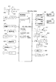
図10は、第1実施形態に係る耕深制御装置のブロック図である。
該耕深制御装置は、前記耕耘リアカバー437の回動角度に基づき、前記車輌本体50に対して昇降可能に連結された前記ロータリー耕耘機400の検出耕深位置hDを前記耕深設定器626による設定耕深位置hRに追従させる自動耕深制御を行うように構成されている。
(First embodiment)
Next, a first embodiment of a tilling depth control device according to the present invention will be described.
FIG. 10 is a block diagram of the tilling depth control apparatus according to the first embodiment.
The tilling depth control device uses the tilling
具体的には、図10に示すように、該耕深制御装置は、前記昇降用アクチュエータとして作用する前記昇降制御油圧シリンダ220と、前記耕深深さ設定手段として作用する前記耕深設定器626と、前記ロータリー耕耘機400の耕深位置を検出する耕深位置検出手段として作用するリヤカバーセンサ624と、前記自動耕深制御を司る制御手段として作用する耕深制御コントローラ600とを備えている。
Specifically, as shown in FIG. 10, the tilling depth control device includes the lifting control
前述の通り、前記リヤカバーセンサ624は、前記ロータリー耕耘機400の耕深位置hDを検出する耕深位置検出手段として作用する。
即ち、前記ロータリー耕耘機400の耕深位置hD(図8(a)参照)に応じて、前記耕耘上面カバー435に対する前記耕耘リヤカバー437の回動位置が変化する。従って、前記リヤカバーセンサ624によって、前記耕耘上面カバー435に対する前記耕耘リヤカバー437の回動位置を検出することによって、前記ロータリー耕耘機400の耕深位置hDを検出することができる。
詳しくは、前記リヤカバーセンサ624は、前記耕耘上面カバー435に対する前記耕耘リヤカバー437の回動位置として、前記耕耘上面カバー435に対する前記耕耘リヤカバー437の回動角度θD(図8(a)参照)を検出し得るように構成され、この検出回動角度θDは、例えば、鉛直Vを基準にした回動角度とすることができる。
本実施の形態においては、該リヤカバーセンサ624は、前記耕耘上面カバー435の後部上面に配置されたポテンショメータ型とされている(図2、図5、図6及び図8参照)。
なお、前記リヤカバーセンサ624と前記耕耘リヤカバー437とは、センサアーム437b及びセンサリンク437c等を介して連結されている(図2参照)。
As described above, the
That is, the rotation position of the tilling
Specifically, the
In the present embodiment, the
The
前記耕深制御コントローラ600は、前記種々の設定手段及びセンサからの信号を入力して、前記昇降用アクチュエータ及び前記傾動用アクチュエータへ制御信号を出力するように構成されている。
即ち、該耕深制御コントローラ600は、図10に示すように、入力系が前記耕深設定器626,前記リヤカバーセンサ624に電気的に接続されると共に、出力系が前記上昇制御電磁弁502及び前記下降制御電磁弁503に電気的に接続されている。
The
That is, as shown in FIG. 10, the
詳しくは、該耕深制御コントローラ600は、図10に示すように、前記各種センサ等から入力される信号に基づいて演算処理を実行する制御演算手段を含む中央処理装置601(以下CPUという)と、制御プログラム等を格納したり、後述する各種関係式又はマップに関する所定のデータ等を記憶するROM602と、前記CPU601の演算中に生成されるデータを一時的に保持するRAM603とを備えている。また、前記CPU601は時計用のタイマを内蔵している。
斯かる耕深制御コントローラ600は電源印加用キースイッチ611を介してバッテリ612に接続されている。なお、前記キースイッチ611は、前記エンジン4を始動するためのスタータ613に接続される。
Specifically, as shown in FIG. 10, the
Such a
なお、前記リアカバーセンサ624は、前記耕深制御コントローラ600に電気的に接続されている。前記耕深制御コントローラ600は、該リアカバーセンサ624の出力の中から限定された帯域の信号出力を取り出すためのフィルタ部625を有している。
斯かるフィルタ部625を設けることにより、前記リアカバーセンサ624の検出感度変化の影響を抑制することができる。これについては後ほど詳述する。
The
By providing such a
本実施の形態においては、前記耕深制御コントローラ600には、図10に示すように、前記エンジン4の回転を制御する電子ガバナコントローラ614が接続されている。
該電子ガバナコントローラ614には、前記エンジン4の燃料を調節するガバナ615と、前記エンジン4の回転数を検出するエンジン回転センサ616とが接続されている。
In the present embodiment, an
The
前記電子ガバナコントローラ614は、作業者にて前記スロットルレバー617が手動操作されると、該スロットルレバー617の回動位置を検出するスロットルポテンショメータ618の検出情報に基づいて、該スロットルレバー617の設定回転数と前記エンジン4の回転数とが一致するように、スロットルソレノイド619にて燃料調節ラック(図示省略)の位置を自動的に調節する制御を実行する。これにより、前記エンジン4の回転は、負荷の変動に拘わらず、前記スロットルレバー617の位置に応じた所定回転数に維持され得る。
When the
さらに、本実施の形態に係る前記耕深制御装置は、前記ロータリ耕耘機400の検出上下高さ位置hL(図8(b)参照)を、上下位置設定手段による設定高さ位置hSに追従させる自動高さ制御を行えるように構成されている。
具体的には、図10に示すように、該耕深制御装置は、前記構成に加えて、前記上下位置設定手段として作用する前記作業機昇降レバー22と、前記ロータリー耕耘機400の前記車輌本体に対する上下位置を検出する上下位置検出手段とを備えている。
本実施の形態においては、前記上下位置検出手段としてリフト角センサ627が備えられている。
該リフト角センサ627は、前記ロータリ耕耘機400の対機体高さ(前記車輌本体50に対する前記ロータリ耕耘機400の相対高さ)hLを検出し得るように構成されている。
具体的には、該リフト角センサ627は、前記リフトアーム221,222のリフト角度θL(図8(b)参照)を検出するように構成されており、例えば、ポテンショメータ型のものが使用され得る。
該リフト角センサ627は、前記作業機用昇降機構200と前記左リフトアーム221との連結箇所に配置されている(図3及び図4参照)。
Furthermore, the tilling depth control device according to the present embodiment causes the detected vertical height position hL (see FIG. 8B) of the
Specifically, as shown in FIG. 10, in addition to the above configuration, the tilling depth control device includes the working
In the present embodiment, a
The
Specifically, the
The
そして、前記耕深制御コントローラ600は、前記自動耕深制御に加えて、前記自動高さ制御を司るように構成されている。
具体的には、該耕深制御コントローラ600は、前記上下位置設定手段及び前記上下位置検出手段からの信号を入力して、前記昇降用アクチュエータへ制御信号を出力するように構成されている。
即ち、該耕深制御コントローラ600は、図10に示すように、入力系が前記作業機昇降レバー22及び前記リフト角センサ627にも電気的に接続されている。
The
Specifically, the
That is, as shown in FIG. 10, the
さらに、本実施の形態に係る前記耕深制御装置は、前記ロータリ耕耘機400の前記車輌本体50に対する検出傾斜状態t(図9参照)を前記傾斜設定器623による設定傾斜状態tSに追従させる自動傾き制御を行えるように構成されている。
具体的には、図10に示すように、該耕深制御装置は、前記構成に加えて、前記傾動用アクチュエータとして作用する前記傾斜制御油圧シリンダ240と、前記傾斜設定手段として作用する前記傾斜設定器623と、前記ロータリー耕耘機400の傾斜状態を検出する作業機傾斜状態検出手段として作用する作業機ポジションセンサ622とを備えている。
Further, the tilling depth control device according to the present embodiment automatically makes the detected tilt state t (see FIG. 9) of the
Specifically, as shown in FIG. 10, in addition to the above-described configuration, the tilling depth control device includes the tilt control
前記作業機ポジションセンサ622は、前記車輌本体50に対する前記ロータリー耕耘機400の左右方向に関する相対的な傾斜角度を検出するように構成されており、例えば、ポテンショメータ型のものが使用され得る。
該作業機ポジションセンサ622は、詳細は図示していないが、例えば、前記耕耘上面カバー435の上方に位置する前記メインビーム420の左右中央箇所に配置され得る。
The work
The work
そして、前記耕深制御コントローラ600は、前記自動耕深制御及び前記自動高さ制御に加えて、前記自動傾き制御を司るように構成されている。
具体的には、該耕深制御コントローラ600は、前記傾斜設定手段623及び前記作業機傾斜状態検出手段622からの信号を入力して、前記傾動用アクチュエータ240へ制御信号を出力するように構成されている。
即ち、該耕深制御コントローラ600は、図10に示すように、入力系が前記傾斜設定器623及び前記作業機ポジションセンサ622にも電気的に接続されると共に、出力系が前記傾斜制御電磁弁504に電気的に接続されている。
The
Specifically, the
That is, as shown in FIG. 10, the
さらに、本実施の形態に係る耕深制御装置には、機体ローリングセンサ621、前記車輌本体50の前後方向に関する傾斜状態を検出する車輌傾斜状態検出手段として作用するピッチング角センサ629及び車速センサ628が備えられている。
Further, the tilling depth control apparatus according to the present embodiment includes a
該機体ローリングセンサ621は、前記車輌本体50の左右方向に関する傾斜角度を検出する為のものであり、例えば、振子式のものが使用され得る。
本実施の形態においては、該機体ローリングセンサ621は、前記作業機用昇降機構200の上面で且つ前記操縦座席7の後方の箇所に配置されている(図1〜図4参照)。
前記ピッチング角センサ629は、前記車輌本体50の前後方向に関する傾斜角度を検出する為のものであり、例えば、振子式のものが使用され得る。
また該車速センサ628は、前後四輪2,3の回転速度(走行速度)を検出するためのものである。
The
In the present embodiment, the
The
The
図11は第1実施形態の耕深制御装置にてロータリー耕耘機400を耕深制御する際の制御ブロック線図である。
FIG. 11 is a control block diagram when plowing depth control is performed on the
該耕深制御コントローラ600は、さらに、前記ロータリー耕耘機400の検出耕深位置hDと前記耕深設定器626による設定耕深位置hRとの偏差Δhの大きさに基づき前記自動耕深制御における制御ゲインKp、Ki,Kdを変更するように構成されている。即ち、前記偏差Δhの大きさによって制御ゲインを選択するように構成されている(図11(a)参照)。
前記「偏差Δhの大きさによる制御ゲインの選択」に代えて、若しくは、加えて、該耕深制御コントローラ600は、前記タイマにて前記偏差Δhの大きさの所定時間内における積分値に基づき前記自動耕深制御における制御ゲインKp、Ki,Kdを変更するように構成されている。即ち、前記偏差Δhの積分値の大きさによって制御ゲインを選択するように構成されている(図11(b)参照)。
前記「偏差Δhの大きさによる制御ゲインの選択」及び/又は前記「偏差Δhの積分値の大きさによる制御ゲインの選択」に代えて、若しくは、加えて、該耕深制御コントローラ600は、前記偏差Δhの変化割合の大きさに基づき前記自動耕深制御における制御ゲインKp、Ki,Kdを変更するように構成されている。即ち、前記偏差Δhの微分値の大きさによって制御ゲインを選択するように構成されている(図11(c)参照)。
ここで、Kは制御ゲインであり、添字pのゲインは比例ゲイン、添字iのゲインは積分ゲイン、添字dのゲインは微分ゲインを示す。
The
Instead of or in addition to the “selection of control gain according to the magnitude of the deviation Δh”, the
In place of or in addition to the “selection of control gain based on the magnitude of the deviation Δh” and / or the “selection of control gain based on the magnitude of the integrated value of the deviation Δh”, the
Here, K is a control gain, the gain of subscript p indicates a proportional gain, the gain of subscript i indicates an integral gain, and the gain of subscript d indicates a differential gain.
斯かる構成を備えることにより、前記偏差Δh、前記偏差Δhの積分値及び前記偏差Δhの微分値の大きさのうち少なくとも一つに応じて前記制御ゲインKp、Ki,Kdを変更することができる。
本実施の形態においては、前記偏差Δh及び/又は前記偏差Δhの微分値の大きさが大きくなるに従って前記制御ゲインKp、Ki,Kdを小さくすることで、前記偏差Δhが大きい場合におけるオーバーシュート現象を有効に防止しつつ、可及的速やかに耕深位置hDを設定耕深位置hRに追従させることができるようになっている。これにより、自動耕深制御の安定化を図ることができる。
また、前記偏差Δhの積分値の大きさが所定の閾値以内の場合には前記制御ゲインKp、Ki,Kdを所定の制御ゲインと等しいか又は前記所定制御ゲインより大きくし、且つ、前記偏差Δhの積分値の大きさが前記所定閾値よりも大きい場合には前記制御ゲインKp、Ki,Kdを前記所定制御ゲインより小さくすることで、前記偏差Δhが大きい場合におけるオーバーシュート現象を有効に防止しつつ、可及的速やかに耕深位置hDを設定耕深位置hRに追従させることができるようにもなっている。これにより、自動耕深制御の安定化を図ることができる。また、この場合、持続的な外乱の入力があった場合であっても、前記ロータリ耕耘機400の昇降制御の安定化を図ることができる。
With such a configuration, the control gains Kp, Ki, and Kd can be changed according to at least one of the magnitude of the deviation Δh, the integral value of the deviation Δh, and the differential value of the deviation Δh. .
In the present embodiment, the control gain Kp, Ki, Kd is decreased as the deviation Δh and / or the differential value of the deviation Δh increases, so that an overshoot phenomenon occurs when the deviation Δh is large. In this way, the tilling position hD can be made to follow the set tilling position hR as quickly as possible. Thereby, stabilization of automatic tilling control can be aimed at.
When the magnitude of the integrated value of the deviation Δh is within a predetermined threshold, the control gains Kp, Ki, Kd are equal to or larger than the predetermined control gain, and the deviation Δh When the magnitude of the integrated value is larger than the predetermined threshold, the control gains Kp, Ki, Kd are made smaller than the predetermined control gain, thereby effectively preventing the overshoot phenomenon when the deviation Δh is large. However, the tilling position hD can be made to follow the set tilling position hR as quickly as possible. Thereby, stabilization of automatic tilling control can be aimed at. Further, in this case, even when there is a continuous disturbance input, the lifting control of the
なお、前記フィルタ部625の遮断周波数Fcの範囲は、本実施の形態では、基準となる固定の基準遮断周波数範囲としている。また、本実施の形態では、前記偏差Δhの大きさについて、所定時間内における積分値を求めるが、前記積分値に代えて、平均値を求めてもよい。この場合の平均値は、単純平均値、重みつき平均値、単純移動平均値、重みつき移動平均値のうち何れであってもよい。また、前記所定時間内における前記積分値や前記平均値を求めるようにしてもよいが、所定サンプリング数における前記積分値や前記平均値を求めるようにしてもよい。
In the present embodiment, the range of the cutoff frequency Fc of the
図12に、前記制御ゲインKpと前記偏差Δhの大きさ(絶対値)との関係の一例を示す制御ゲインマップを示す。
前記ROM602には、例えば、前記制御ゲインKpと前記偏差Δhの大きさとの関係を示す制御ゲイン演算用関係式又は制御ゲインマップが予め記憶されている。
この制御ゲイン演算用関係式を制御ゲインマップとした場合を図12に示している。図12では、前記偏差Δhの大きさを横軸に採り、制御ゲインKpを縦軸に採っている。
FIG. 12 shows a control gain map showing an example of the relationship between the control gain Kp and the magnitude (absolute value) of the deviation Δh.
In the
FIG. 12 shows a case where this control gain calculation relational expression is used as a control gain map. In FIG. 12, the horizontal axis represents the magnitude of the deviation Δh, and the vertical axis represents the control gain Kp.
斯かる構成を備えることにより、前記耕深制御コントローラ600は、前記偏差Δhの大きさが大きくなるに従って前記制御ゲインKpを小さくする。
なお、前記偏差Δhの大きさとこれに対応する制御ゲインKpとが関連づけられたデータを、テーブルマップとして前記ROM602に予め記憶させるようにしてもよい。
また、前記制御ゲインKp,Ki,Kdと前記偏差Δhの所定時間内(又は所定サンプリング数)における積分値(若しくは平均値)の大きさとの関係を得るための手段は、例えば、前記偏差Δhの所定時間内(又は所定サンプリング数)における積分値(若しくは平均値)の大きさとこれに対応する制御ゲインKp,Ki,Kdとが関連づけられた関係式又は制御ゲインマップ或いはテーブルマップであってもよい。
前記制御ゲインKp,Ki,Kdと前記偏差Δhの変化割合(微分値)の大きさとの関係を得るための手段は、例えば、前記偏差Δhの変化割合(微分値)の大きさとこれに対応する制御ゲインKp,Ki,Kdとが関連づけられた関係式又は制御ゲインマップ或いはテーブルマップであってもよい。
これらの関係は各制御ゲインKp,Ki,Kd共通でも独立でもかまわない。本実施形態では、各制御ゲインKp,Ki,Kd共通としている。なお、各制御ゲインKp,Ki,Kdのうち何れかのゲインを0「ゼロ」として不使用にすることができる。
By having such a configuration, the
Note that data in which the magnitude of the deviation Δh is associated with the control gain Kp corresponding thereto may be stored in advance in the
The means for obtaining the relationship between the control gains Kp, Ki, Kd and the magnitude of the integrated value (or average value) within a predetermined time (or a predetermined sampling number) of the deviation Δh is, for example, the deviation Δh It may be a relational expression, a control gain map, or a table map in which a magnitude of an integrated value (or an average value) within a predetermined time (or a predetermined sampling number) and a corresponding control gain Kp, Ki, Kd are associated with each other. .
The means for obtaining the relationship between the control gains Kp, Ki, Kd and the magnitude of the change rate (differential value) of the deviation Δh corresponds to the magnitude of the change rate (differential value) of the deviation Δh, for example. It may be a relational expression associated with the control gains Kp, Ki, Kd, a control gain map, or a table map.
These relationships may be common to each control gain Kp, Ki, Kd or independent. In this embodiment, each control gain Kp, Ki, Kd is common. It should be noted that any one of the control gains Kp, Ki, Kd can be set to 0 “zero” and not used.
前記制御ゲインKp,Ki,Kdと前記偏差Δhの微分値の大きさとの関係を得るための手段は、本実施の形態では、前記制御ゲインKp,Ki,Kdと前記偏差Δhの微分値の大きさとの関係を示す制御ゲイン演算用関係式又は制御ゲインマップ或いはテーブルマップであって、図12に示す関係と同様の関係を示すものを用いている。例えば、前記ROM602には、前記制御ゲインKp,Ki,Kdと前記偏差Δhの微分値の大きさとの関係を示す制御ゲイン演算用関係式又は制御ゲインマップも予め記憶されている。
斯かる構成を備えることにより、前記耕深制御コントローラ600は、前記偏差Δhの微分値の大きさが大きくなるに従って前記制御ゲインKp,Ki,Kdを小さくする。
In this embodiment, the means for obtaining the relationship between the control gains Kp, Ki, Kd and the magnitude of the differential value of the deviation Δh is the magnitude of the differential value of the control gains Kp, Ki, Kd and the deviation Δh. A control gain calculation relational expression, a control gain map, or a table map showing the relationship between the relationship and the relationship shown in FIG. 12 is used. For example, the
By providing such a configuration, the
また、前記偏差Δhの積分値の大きさに応じた前記制御ゲインKp,Ki,Kdは、本実施の形態では、次にようにして求めている。即ち、前記タイマによる所定時間内において、前記偏差Δhが予め決められた閾値偏差Δhtを上回ったとき、カウンタCを加算していき、該カウンタCの値が予め決められた閾値カウンタCtを超えたときに、前記制御ゲインKpに係数α(但し0<α<1)を掛ける一方、前記偏差Δhが予め決められた目標範囲Δhd以内にある場合は、該カウンタCをリセットし、前記制御ゲインKpを元の値に戻す。そして所定時間経過後に得られた制御ゲインKpを各制御ゲインKp,Ki,Kdとし、こうして各制御ゲインKp,Ki,Kdを得るようにしている。これについては後述する図14のフローチャートで詳述する。
斯かる構成を備えることにより、前記耕深制御コントローラ600は、前記偏差Δhの積分値の大きさが前記閾値偏差Δht以内の場合には前記制御ゲインKp,Ki,Kdを元の制御ゲインと等しいか又は大きく(ここでは等しく)し、且つ、前記積分値の大きさが前記閾値偏差Δhtより大きい場合には前記制御ゲインKp,Ki,Kdを元の制御ゲインより小さくする。
なお、前記閾値偏差Δht、前記閾値カウンタCt及び前記目標範囲Δhdは、前記ROM602に予め記憶されている。
In the present embodiment, the control gains Kp, Ki, and Kd corresponding to the magnitude of the integrated value of the deviation Δh are obtained as follows. That is, when the deviation Δh exceeds a predetermined threshold deviation Δht within a predetermined time by the timer, the counter C is incremented, and the value of the counter C exceeds the predetermined threshold counter Ct. When the control gain Kp is multiplied by a coefficient α (where 0 <α <1) while the deviation Δh is within a predetermined target range Δhd, the counter C is reset and the control gain Kp To the original value. The control gain Kp obtained after the lapse of a predetermined time is set as each control gain Kp, Ki, Kd, and thus each control gain Kp, Ki, Kd is obtained. This will be described in detail with reference to the flowchart of FIG.
By providing such a configuration, the tilling
The threshold deviation Δht, the threshold counter Ct, and the target range Δhd are stored in advance in the
次に、図11乃至図15を参照しながら前記耕深制御コントローラ600による前記ロータリー耕耘機400の耕深制御動作の一例を以下に詳述する。
(偏差Δhの大きさによる制御ゲインの選択)
先ず、第1実施形態に係る自動耕深制御において前記偏差Δhの大きさによって前記制御ゲインKp,Ki,Kdを選択する場合について説明する。
図13に、第1実施形態に係る自動耕深制御において前記偏差Δhの大きさによって前記制御ゲインKp,Ki,Kdを選択するためのフローチャートを示す。
Next, an example of the tilling depth control operation of the
(Selection of control gain according to deviation Δh)
First, the case where the control gains Kp, Ki, and Kd are selected according to the magnitude of the deviation Δh in the automatic tilling control according to the first embodiment will be described.
FIG. 13 shows a flowchart for selecting the control gains Kp, Ki, Kd according to the magnitude of the deviation Δh in the automatic tilling control according to the first embodiment.
図13に示す耕深制御では、ステップS1からの処理に先立ち、後述するステップS5の処理で用いる偏差の累積値Δhi及び変数Δh1に、初期値として「0(ゼロ)」が代入される。なお、変数Δh1はステップS8において前回の偏差Δhの値を格納しておく為のものである。 In the plowing depth control shown in FIG. 13, prior to the processing from step S1, “0 (zero)” is assigned as an initial value to the accumulated deviation value Δhi and variable Δh1 used in the processing of step S5 described later. The variable Δh1 is for storing the previous deviation Δh in step S8.
図13に示す耕深制御では、先ず、前記リヤカバーセンサ624による検出上下回動角度θDを読み込む(ステップS1)。該読み込まれた検出上下回動角度θDに基づく前記ロータリー耕耘機400の検出耕深位置hDと前記耕深設定器626による設定耕深位置hRとの偏差Δhを算出する(ステップS2)。
In the tilling depth control shown in FIG. 13, first, the detected vertical rotation angle θD by the
次に、前記ROM602に予め記憶された、制御ゲインと偏差の大きさとの関係を示す制御ゲイン演算用関係式又は制御ゲインマップを該ROM602から読み出す(ステップS3)。該読み出された制御ゲイン演算用関係式又は制御ゲインマップと、前記ステップS2で算出された偏差Δhとに基づき、前記偏差Δhの大きさに応じた制御ゲインKp,Ki,Kdを求める(ステップS4)。この場合の前記制御ゲインKp,Ki,Kdは、前記偏差Δhの大きさが大きくなるに従って小さい値になる(図12参照)。
Next, the control gain calculation relational expression or control gain map indicating the relationship between the control gain and the deviation magnitude stored in advance in the
次に、前記偏差Δhの積分・微分を計算する(ステップS5)。
具体的には、次の式(1)に示すように、偏差の累積値Δhiに前記偏差Δhを加算するとともに、次の式(2)に示すように、前記偏差Δhから前回の偏差Δh1(但し初期値は「0」)を差し引いた前回偏差との差Δhdを算出する。
Δhi=Δhi+Δh・・・式(1)
Δhd=Δh−Δh1・・・式(2)
Next, the integral / derivative of the deviation Δh is calculated (step S5).
Specifically, as shown in the following equation (1), the deviation Δh is added to the cumulative value Δhi of the deviation, and as shown in the following equation (2), the deviation Δh1 ( However, the difference Δhd from the previous deviation obtained by subtracting “0” as the initial value is calculated.
Δhi = Δhi + Δh (1)
Δhd = Δh−Δh1 (2)
次に、出力値Yを計算する(ステップS6)。
具体的には、前記ステップS2で得られた偏差Δhと、前記ステップS4で得られた制御ゲインKp,Ki,Kdと、前記ステップS5で得られた偏差の累積値Δhi及び前回偏差との差Δhdとを次の式(3)に代入して、出力値Yを算出する。
Y=KpΔh+KiΔhi+KdΔhd・・・式(3)
Next, the output value Y is calculated (step S6).
Specifically, the difference between the deviation Δh obtained in the step S2, the control gains Kp, Ki, Kd obtained in the step S4, the cumulative value Δhi of the deviation obtained in the step S5 and the previous deviation. The output value Y is calculated by substituting Δhd into the following equation (3).
Y = KpΔh + KiΔhi + KdΔhd Equation (3)
そして、出力値Yを出力する(ステップS7)。
これにより、耕深制御の際には、前記ステップS6で得られた出力値Yと、前記リヤカバーセンサ624で読み込まれた検出上下回動角度θDに基づく検出耕深位置hDとにより、該検出耕深位置hDが前記耕深設定器626の設定回動角度θRに基づく設定耕深位置hRとなるように前記昇降制御油圧シリンダ220の自動昇降制御量が算出される。こうして算出された自動昇降制御量にて前記上昇制御電磁弁502又は前記下降制御電磁弁503が作動され、前記昇降制御油圧シリンダ220による前記ロータリー耕耘機400の下降又は上昇の動作が実行される。
And the output value Y is output (step S7).
As a result, during tilling control, the detected tillage position hD based on the output value Y obtained in step S6 and the detected tilling position hD based on the detected vertical rotation angle θD read by the
次に、前記変数Δh1に前記ステップS2で算出された偏差Δhの値を代入し(ステップS8)、ステップS9に移行する。 Next, the value of the deviation Δh calculated in step S2 is substituted for the variable Δh1 (step S8), and the process proceeds to step S9.
ステップS9では、前記自動耕深制御動作終了か否かを判断し、自動耕深制御動作中と判断したときは、ステップS1〜ステップS8までの動作を順次繰り返す一方、自動耕深制御動作が終了したと判断したときには、前記自動耕深制御を終了する。 In step S9, it is determined whether or not the automatic tilling depth control operation is completed. When it is determined that the automatic tilling depth control operation is being performed, the operations from step S1 to step S8 are sequentially repeated while the automatic tilling depth control operation is completed. When it is determined that the automatic plowing depth control has been completed, the automatic plowing depth control is terminated.
(偏差Δhの積分値の大きさによる制御ゲインの選択)
次に、第1実施形態に係る自動耕深制御において前記偏差Δhの積分値の大きさによって前記制御ゲインKp,Ki,Kdを選択する場合について説明する。
図14に、第1実施形態に係る自動耕深制御において前記偏差Δhの積分値の大きさによって前記制御ゲインKp,Ki,Kdを選択するためのフローチャートを示す。
図14に示すフローチャートは、図13に示すフローチャートにおいて、前記ステップS1〜S4の代わりに前記偏差Δhの積分値を求めるステップS101〜S114を設けている。図14に示すフローチャートは、ステップS101〜S114以外は図13のフローチャートと実質的に同じものである。従って、ここでは、これらのステップを中心に説明する。
(Selection of control gain based on the integrated value of deviation Δh)
Next, the case where the control gains Kp, Ki, Kd are selected according to the magnitude of the integrated value of the deviation Δh in the automatic tilling control according to the first embodiment will be described.
FIG. 14 shows a flowchart for selecting the control gains Kp, Ki, Kd according to the magnitude of the integrated value of the deviation Δh in the automatic tilling control according to the first embodiment.
The flowchart shown in FIG. 14 includes steps S101 to S114 for obtaining an integrated value of the deviation Δh instead of the steps S1 to S4 in the flowchart shown in FIG. The flowchart shown in FIG. 14 is substantially the same as the flowchart of FIG. 13 except for steps S101 to S114. Therefore, here, these steps will be mainly described.
図14に示す耕深制御では、先ず、初期値としてカウンタCに「0」を代入する(ステップS101)。前記ROM602に予め記憶された前記閾値偏差Δht、閾値カウンタCt及び目標範囲Δhdを該ROM602から読み出す(ステップS102)。
In the tilling depth control shown in FIG. 14, first, “0” is substituted into the counter C as an initial value (step S101). The threshold deviation Δht, threshold counter Ct, and target range Δhd stored in advance in the
次に、前記制御ゲインKpの値を変数Kp’に代入する(ステップS103)。
前記リヤカバーセンサ624による検出上下回動角度θDを読み込み(ステップS104)、該読み込まれた検出上下回動角度θDに基づく前記ロータリー耕耘機400の検出耕深位置hDと前記耕深設定器626による設定耕深位置hRとの偏差Δhを算出する(ステップS105)。
Next, the value of the control gain Kp is substituted into a variable Kp ′ (step S103).
The detected vertical rotation angle θD detected by the
次に、前記ステップS105で算出された偏差Δhが前記ROM602から読み出された閾値偏差Δhtより大きいか否かを判断する(ステップS106)。
具体的には、前記偏差Δhが前記閾値偏差Δhtより大きいと判断した場合には、ステップS107に移行する一方、前記偏差Δhが前記閾値偏差Δhtと等しいか又は前記閾値偏差Δhtより小さいと判断した場合には、ステップS108に移行する。
前記ステップS106で前記偏差Δhが前記閾値偏差Δhtより大きいと判断した場合、前記カウンタCに1を加算する(ステップS107)。
Next, it is determined whether or not the deviation Δh calculated in step S105 is larger than the threshold deviation Δht read from the ROM 602 (step S106).
Specifically, when it is determined that the deviation Δh is larger than the threshold deviation Δht, the process proceeds to step S107, while it is determined that the deviation Δh is equal to or smaller than the threshold deviation Δht. In that case, the process proceeds to step S108.
If it is determined in step S106 that the deviation Δh is greater than the threshold deviation Δht, 1 is added to the counter C (step S107).
次に、前記カウンタCが前記ROM602から読み出された閾値カウンタCtより大きいか否かを判断する(ステップS108)。
具体的には、前記カウンタCが前記閾値カウンタCtより大きいと判断した場合には、ステップS109に移行する一方、前記カウンタCが前記閾値カウンタCtと等しいか又は前記閾値カウンタCtより小さいと判断した場合には、ステップS110に移行する。
前記ステップS108で前記カウンタCが前記閾値カウンタCtより大きいと判断した場合、前記制御ゲインKpに係数α(但し0<α<1、例えば、α=0.5)を掛ける(ステップS109)。
Next, it is determined whether or not the counter C is larger than a threshold counter Ct read from the ROM 602 (step S108).
Specifically, when it is determined that the counter C is larger than the threshold counter Ct, the process proceeds to step S109, while it is determined that the counter C is equal to or smaller than the threshold counter Ct. In the case, the process proceeds to step S110.
If it is determined in step S108 that the counter C is greater than the threshold counter Ct, the control gain Kp is multiplied by a coefficient α (where 0 <α <1, for example, α = 0.5) (step S109).
前記ステップS105で算出された偏差Δhが前記ROM602から読み出された目標範囲Δhd内にあるか否かを判断する(ステップS110)。
具体的には、前記偏差Δhが前記目標範囲Δhd内にあると判断した場合には、ステップS111に移行する一方、前記偏差Δhが前記目標範囲Δhd内にないと判断した場合には、ステップS113に移行する。
前記ステップS110で前記偏差Δhが前記目標範囲Δhd内にあると判断した場合、前記カウンタCを「0」にリセットする(ステップS111)。前記制御ゲインKpに前記変数Kp’の値を代入して該制御ゲインKpを元に戻し(ステップS112)、ステップS113に移行する。
It is determined whether or not the deviation Δh calculated in step S105 is within the target range Δhd read from the ROM 602 (step S110).
Specifically, when it is determined that the deviation Δh is within the target range Δhd, the process proceeds to step S111, while when it is determined that the deviation Δh is not within the target range Δhd, step S113 is performed. Migrate to
If it is determined in step S110 that the deviation Δh is within the target range Δhd, the counter C is reset to “0” (step S111). The value of the variable Kp ′ is substituted for the control gain Kp to restore the control gain Kp (step S112), and the process proceeds to step S113.
次に、前記タイマによって所定時間経過したか否かを判断する(ステップS113)。
具体的には、所定時間経過していないと判断した場合には、ステップS104に戻る一方、所定時間経過したと判断した場合には、ステップS114に移行する。
Next, it is determined whether or not a predetermined time has elapsed by the timer (step S113).
Specifically, when it is determined that the predetermined time has not elapsed, the process returns to step S104, whereas when it is determined that the predetermined time has elapsed, the process proceeds to step S114.
ステップS114では、所定時間経過後に得られた、前記偏差Δhの積分値の大きさに応じた制御ゲインkpの値を前記制御ゲインKi,Kdに代入する。
そして、前記ステップS6において前記ステップS101〜S114で得られた偏差Δh及び制御ゲインKp,Ki,Kdと、前記ステップS5で得られた偏差の累積値Δhi及び前回偏差との差Δhdとを前記式(3)に代入して、出力値Yを算出する。
In step S114, the value of the control gain kp corresponding to the magnitude of the integral value of the deviation Δh, obtained after a predetermined time has elapsed, is substituted into the control gains Ki and Kd.
In step S6, the deviation Δh and the control gains Kp, Ki, Kd obtained in steps S101 to S114, the accumulated deviation Δhi obtained in step S5, and the difference Δhd from the previous deviation are expressed by the above equation. Substituting into (3), the output value Y is calculated.
(偏差Δhの微分値の大きさによる制御ゲインの選択)
次に、第1実施形態に係る自動耕深制御において前記偏差Δhの微分値の大きさによって前記制御ゲインKp,Ki,Kdを選択する場合について説明する。
図15に、第1実施形態に係る自動耕深制御において前記偏差Δhの微分値の大きさによって前記制御ゲインKp,Ki,Kdを選択するためのフローチャートを示す。
図15に示すフローチャートは、図13に示すフローチャートにおいて、前記ステップS3及びS4の代わりにそれぞれステップS30及びS40を設け、ステップS2とS30との間にステップS21を、またステップS40とS5との間にステップS41を追加している。図14に示すフローチャートは、ステップS30,S40,S21及びS41以外は図13のフローチャートと実質的に同じものである。従って、ここでは、これらのステップを中心に説明する。
(Selection of control gain according to the differential value of deviation Δh)
Next, the case where the control gains Kp, Ki, Kd are selected according to the differential value of the deviation Δh in the automatic tilling control according to the first embodiment will be described.
FIG. 15 shows a flowchart for selecting the control gains Kp, Ki, Kd according to the magnitude of the differential value of the deviation Δh in the automatic tilling control according to the first embodiment.
The flowchart shown in FIG. 15 is different from the flowchart shown in FIG. 13 in that steps S30 and S40 are provided instead of steps S3 and S4, step S21 is provided between steps S2 and S30, and step S40 and S5 are provided. Step S41 is added. The flowchart shown in FIG. 14 is substantially the same as the flowchart of FIG. 13 except for steps S30, S40, S21, and S41. Therefore, here, these steps will be mainly described.
図15に示す耕深制御では、ステップS1からの処理に先立ち、後述するステップS21の処理で用いる変数Δh2に、初期値として「0(ゼロ)」が代入される。この変数Δh2はステップS41において一回前に処理された偏差Δhの値を格納する為のものである。 In the tilling depth control shown in FIG. 15, prior to the processing from step S <b> 1, “0 (zero)” is substituted as an initial value into a variable Δh <b> 2 used in the processing of step S <b> 21 described later. This variable Δh2 is for storing the value of the deviation Δh processed once in step S41.
ステップS21では、前記ステップS2で算出された偏差Δhの微分値を求める為に、次の式(4)に示すように、該偏差Δhと一回前に処理された偏差Δhの値を格納する変数Δh2(但し初期値は「0」)との差の絶対値を求め、該差の絶対値を変数Δhjに代入する。
Δhj=|Δh−Δh2|・・・式(4)
In step S21, in order to obtain the differential value of the deviation Δh calculated in step S2, the deviation Δh and the value of the deviation Δh processed once before are stored as shown in the following equation (4). The absolute value of the difference from the variable Δh2 (where the initial value is “0”) is obtained, and the absolute value of the difference is substituted into the variable Δhj.
Δhj = | Δh−Δh2 | (4)
ステップS30では、前記ROM602に予め記憶された、制御ゲインと偏差の微分値の大きさとの関係を示す制御ゲイン演算用関係式又は制御ゲインマップを該ROM602から読み出す。ステップS40では、該読み出された制御ゲイン演算用関係式又は制御ゲインマップと、前記ステップS21で算出された変数Δhjとに基づき、前記偏差Δhの微分値Δhj(変化割合)の大きさに応じた制御ゲインKp,Ki,Kdを求め、ステップS41に移行する。この場合の前記制御ゲインKp,Ki,Kdは、前記偏差Δhの微分値Δhjの大きさが大きくなるに従って小さい値になる。
In step S <b> 30, a control gain calculation relational expression or a control gain map indicating the relationship between the control gain and the differential value of the deviation stored in advance in the
ステップS41では、前記変数Δh2に前記ステップS2で算出された偏差Δhの値を代入する。
そして、前記ステップS6において、前記ステップS2で得られた偏差Δhと、前記ステップS40で得られた制御ゲインKp,Ki,Kdと、前記ステップS5で得られた偏差の累積値Δhi及び前回偏差との差Δhdとを前記式(3)に代入して、出力値Yを算出する。
In step S41, the value of the deviation Δh calculated in step S2 is substituted for the variable Δh2.
In step S6, the deviation Δh obtained in step S2, the control gains Kp, Ki, Kd obtained in step S40, the accumulated deviation Δhi obtained in step S5, and the previous deviation, The output value Y is calculated by substituting the difference Δhd into the equation (3).
なお、前記制御ゲインKp,Ki,Kdの変更に代えて、若しくは、加えて、前記自動耕深制御を行う際の不感帯幅δを変更することも可能である。
これについて、次の第2の実施形態を参照しながら説明する。
Note that, instead of or in addition to changing the control gains Kp, Ki, Kd, it is also possible to change the dead zone width δ when performing the automatic tilling depth control.
This will be described with reference to the second embodiment.
(第2実施形態)
以下、本発明に係る耕深制御装置の第2実施形態について説明する。
この第2実施形態に係る耕深制御装置は、図10に示す耕深制御装置とは耕深制御コントローラ600が異なる以外は実質的に同じものである。従って、第2実施形態に係る耕深制御装置のブロック図を図10に示すブロック図に代用させ、その詳細な説明を省略する。なお、耕深制御コントローラ600aの参照符号は図10に示す耕深制御コントローラ600の後の括弧内に付してある。後述する第3実施形態についても同様である。
(Second Embodiment)
Hereinafter, 2nd Embodiment of the tilling depth control apparatus which concerns on this invention is described.
The tilling depth control device according to the second embodiment is substantially the same as the tilling depth control device shown in FIG. 10 except that the tilling
第2実施形態に係る耕深制御装置の耕深制御コントローラ600aは、前記第1実施形態に係る耕深制御装置の耕深制御コントローラ600において前記ROM602の代わりにROM602aを備えている。なお、ROM602aの参照符号は図10に示すROM602の後の括弧内に付してある。後述する第3実施形態についても同様である。
The tilling
図16は第2実施形態の耕深制御装置にてロータリー耕耘機400を耕深制御する際の制御ブロック線図である。
FIG. 16: is a control block diagram at the time of plowing control of the
該耕深制御装置は、第1実施形態の耕深制御装置において、前記制御ゲインKp,Ki,Kdを変更する構成に代えて、前記ロータリー耕耘機400の検出耕深位置hDと前記耕深設定器626による設定耕深位置hRとの偏差Δhの大きさに基づき前記自動耕深制御における不感帯幅δを変更するように構成されている。即ち、前記偏差Δhの大きさによって不感帯幅を選択するように構成されている(図16(a)参照)。
前記「偏差Δhの大きさによる不感帯幅の選択」に代えて、若しくは、加えて、該耕深制御コントローラ600aは、前記タイマにて前記偏差Δhの所定時間内における積分値の大きさに基づき前記自動耕深制御における不感帯幅δを変更するように構成されている。即ち、前記偏差Δhの積分値の大きさによって不感帯幅を選択するように構成されている(図16(b)参照)。
前記「偏差Δhの大きさによる不感帯幅の選択」及び/又は前記「偏差Δhの積分値の大きさによる不感帯幅の選択」に代えて、若しくは、加えて、該耕深制御コントローラ600aは、前記偏差Δhの変化割合の大きさに基づき前記自動耕深制御における不感帯幅δを変更するように構成されている。即ち、前記偏差Δhの微分値の大きさによって不感帯幅を選択するように構成されている(図16(c)参照)。
The plowing depth control device is the plowing depth control device according to the first embodiment, instead of the configuration in which the control gains Kp, Ki, Kd are changed, the detected plowing depth position hD of the
Instead of or in addition to the “selection of the dead zone width depending on the magnitude of the deviation Δh”, the
In place of or in addition to the above-mentioned “selection of dead zone width by the magnitude of deviation Δh” and / or “selection of dead zone width by the magnitude of the integrated value of deviation Δh”, the
斯かる構成を備えることにより、前記偏差Δh、前記偏差Δhの積分値及び前記偏差Δhの微分値の大きさのうち少なくとも一つに応じて前記不感帯幅δを変更することができる。
本実施の形態においては、前記偏差Δh及び/又は前記偏差Δhの微分値の大きさが大きくなるに従って前記不感帯幅δを大きくすることで、前記偏差Δhが大きい場合におけるオーバーシュート現象を有効に防止しつつ、可及的速やかに耕深位置hDを設定耕深位置hRに追従させることができるようになっている。これにより、自動耕深制御の安定化を図ることができる。
また、前記偏差Δhの積分値の大きさが所定の閾値以内の場合には前記不感帯幅δを所定の不感帯幅と等しいか又は前記所定不感帯幅より小さくし、且つ、前記偏差Δhの積分値の大きさが前記所定閾値よりも大きい場合には前記不感帯幅δを前記所定不感帯幅より大きくすることで、前記偏差Δhが大きい場合におけるオーバーシュート現象を有効に防止しつつ、可及的速やかに耕深位置hDを設定耕深位置hRに追従させることができるようにもなっている。これにより、自動耕深制御の安定化を図ることができる。また、この場合、持続的な外乱の入力があった場合であっても、前記ロータリ耕耘機400の昇降制御の安定化を図ることができる。
With such a configuration, the dead zone width δ can be changed according to at least one of the magnitude of the deviation Δh, the integral value of the deviation Δh, and the differential value of the deviation Δh.
In the present embodiment, the dead zone width δ is increased as the deviation Δh and / or the differential value of the deviation Δh increases, thereby effectively preventing the overshoot phenomenon when the deviation Δh is large. However, the tilling position hD can be made to follow the set tilling position hR as quickly as possible. Thereby, stabilization of automatic tilling control can be aimed at.
When the integrated value of the deviation Δh is within a predetermined threshold, the dead band width δ is equal to or smaller than the predetermined dead band width, and the integrated value of the deviation Δh When the size is larger than the predetermined threshold value, the dead zone width δ is set larger than the predetermined dead zone width, thereby effectively preventing overshoot phenomenon when the deviation Δh is large, and cultivating as quickly as possible. The deep position hD can be made to follow the set tilling depth position hR. Thereby, stabilization of automatic tilling control can be aimed at. Further, in this case, even when there is a continuous disturbance input, the lifting control of the
なお、前記フィルタ部625の遮断周波数Fcの範囲は、前記第1実施形態と同様、基準となる固定の基準遮断周波数範囲としている。また、本実施の形態では、前記第1実施形態と同様、前記偏差Δhの大きさについて、所定時間内における積分値を求めるが、前記積分値に代えて、平均値を求めてもよい。この場合の平均値は、単純平均値、重みつき平均値、単純移動平均値、重みつき移動平均値のうち何れであってもよい。また、前記所定時間内における前記積分値や前記平均値を求めるようにしてもよいが、所定サンプリング数における前記積分値や前記平均値を求めるようにしてもよい。
The range of the cut-off frequency Fc of the
図17に、前記不感帯幅δと前記偏差Δhの大きさ(絶対値)との関係の一例を示す不感帯マップを示す。
前記ROM602aには、例えば、前記不感帯幅δと前記偏差Δhの大きさとの関係を示す不感帯幅演算用関係式又は不感帯マップが予め記憶されている。
この不感帯幅演算用関係式関係式を不感帯マップとした場合を図17に示している。図17では、前記偏差Δhの大きさを横軸に採り、前記不感帯幅δを縦軸に採っている。
FIG. 17 shows a dead zone map showing an example of the relationship between the dead zone width δ and the magnitude (absolute value) of the deviation Δh.
In the
FIG. 17 shows a case where the dead zone width calculation relational expression is a dead zone map. In FIG. 17, the magnitude of the deviation Δh is taken on the horizontal axis, and the dead zone width δ is taken on the vertical axis.
斯かる構成を備えることにより、前記耕深制御コントローラ600aは、前記偏差Δhの大きさが大きくなるに従って前記不感帯幅δを大きくする。
なお、前記偏差Δhの大きさとこれに対応する不感帯幅δとが関連づけられたデータを、テーブルマップとして前記ROM602aに予め記憶させるようにしてもよい。
ここで、不感帯とは、前記ロータリー耕耘機400の検出耕深位置hDが前記耕深設定器626による設定耕深位置hRを中心とする所定の上下幅範囲内にあれば、前記昇降制御油圧シリンダ220を非駆動とし、検出耕深位置hDが前記上下幅範囲から外れていれば、前記昇降制御油圧シリンダ220を昇降動させて前記ロータリ耕耘機400の耕深位置を設定耕深位置hRに近付ける動作隙間のことをいう。
また、前記不感帯幅δと前記偏差Δhの所定時間内(又は所定サンプリング数)における積分値(若しくは平均値)の大きさとの関係を得るための手段は、例えば、前記偏差Δhの所定時間内(又は所定サンプリング数)における積分値(若しくは平均値)の大きさとこれに対応する不感帯幅δとが関連づけられた関係式又は不感帯マップ或いはテーブルマップであってもよい。
前記不感帯幅δと前記偏差Δhの変化割合(微分値)の大きさとの関係を得るための手段は、例えば、前記偏差Δhの変化割合(微分値)の大きさとこれに対応する不感帯幅δとが関連づけられた関係式又は不感帯マップ或いはテーブルマップであってもよい。
By providing such a configuration, the
Note that data in which the magnitude of the deviation Δh and the dead zone width δ corresponding thereto are associated may be stored in advance in the
Here, the dead zone means that if the detected tilling position hD of the
The means for obtaining the relationship between the dead zone width δ and the magnitude of the integrated value (or average value) within a predetermined time (or a predetermined sampling number) of the deviation Δh is, for example, within a predetermined time of the deviation Δh ( Alternatively, it may be a relational expression, a dead zone map, or a table map in which the magnitude of the integrated value (or average value) in a predetermined sampling number) and the dead zone width δ corresponding thereto are associated.
The means for obtaining the relationship between the dead zone width δ and the magnitude of the change rate (differential value) of the deviation Δh is, for example, the magnitude of the change rate (differential value) of the deviation Δh and the corresponding dead zone width δ. May be a relational expression, a dead zone map, or a table map.
前記不感帯幅δと前記偏差Δhの微分値の大きさとの関係を得るための手段は、本実施の形態では、前記不感帯幅δと前記偏差Δhの微分値の大きさとの関係を示す不感帯幅演算用関係式又は不感帯マップ或いはテーブルマップであって、図17に示す関係と同様の関係を示すものを用いている。例えば、前記ROM602aには、前記不感帯幅δと前記偏差Δhの微分値の大きさとの関係を示す不感帯幅演算用関係式又は不感帯マップも予め記憶されている。
斯かる構成を備えることにより、前記耕深制御コントローラ600aは、前記偏差Δhの微分値の大きさが大きくなるに従って前記不感帯幅δを大きくする。
In this embodiment, the means for obtaining the relationship between the dead zone width δ and the magnitude of the differential value of the deviation Δh is a dead zone width calculation indicating the relationship between the dead zone width δ and the magnitude of the differential value of the deviation Δh. A relational expression, dead zone map, or table map that shows the same relationship as that shown in FIG. 17 is used. For example, the
By providing such a configuration, the
また、前記偏差Δhの積分値の大きさに応じた前記不感帯幅δは、係数αを除き前記第1実施形態と同様にして求めている。これについては後述する図19のフローチャートで説明する。
斯かる構成を備えることにより、前記耕深制御コントローラ600aは、前記偏差Δhの積分値の大きさが閾値偏差Δht’以内の場合には前記不感帯幅δを元の不感帯幅と等しいか又は大きく(ここでは等しく)し、且つ、前記積分値の大きさが前記閾値偏差Δht’より大きい場合には前記不感帯幅δを元の不感帯幅より大きくする。
なお、図19のフローチャートで用いる閾値偏差Δht’、閾値カウンタCt’及び目標範囲Δhd’は、前記ROM602aに予め記憶されている。
Further, the dead zone width δ corresponding to the magnitude of the integrated value of the deviation Δh is obtained in the same manner as in the first embodiment except for the coefficient α. This will be described later with reference to the flowchart of FIG.
By providing such a configuration, the
Note that the threshold deviation Δht ′, the threshold counter Ct ′, and the target range Δhd ′ used in the flowchart of FIG. 19 are stored in advance in the
次に、図16乃至図20を参照しながら前記耕深制御コントローラ600aによる前記ロータリー耕耘機400の耕深制御動作の一例を以下に詳述する。
(偏差Δhの大きさによる不感帯幅の選択)
先ず、第2実施形態に係る自動耕深制御において前記偏差Δhの大きさによって前記不感帯幅δを選択する場合について説明する。
図18に、第2実施形態に係る自動耕深制御において前記偏差Δhの大きさによって前記不感帯幅δを選択するためのフローチャートを示す。
Next, an example of the tilling depth control operation of the
(Selection of dead band width by deviation Δh)
First, the case where the dead zone width δ is selected according to the magnitude of the deviation Δh in the automatic tilling depth control according to the second embodiment will be described.
FIG. 18 shows a flowchart for selecting the dead zone width δ according to the magnitude of the deviation Δh in the automatic tilling control according to the second embodiment.
図18に示すフローチャートは、図13に示すフローチャートにおいて、前記ステップS3及びS4の代わりにそれぞれステップS3’及びS4’を設けている。図18のフローチャートは、S3’及びS4’以外は図13のフローチャートと実質的に同じものである。従って、ここでは、これらのステップを中心に説明する。 The flowchart shown in FIG. 18 is different from the flowchart shown in FIG. 13 in that steps S3 'and S4' are provided instead of steps S3 and S4. The flowchart in FIG. 18 is substantially the same as the flowchart in FIG. 13 except for S3 'and S4'. Therefore, here, these steps will be mainly described.
ステップS3’では、前記ROM602aに予め記憶された、不感帯幅と偏差の大きさとの関係を示す不感帯幅演算用関係式又は不感帯マップを該ROM602aから読み出す。
In step S3 ', a dead band calculation relational expression or a dead band map indicating the relationship between the dead band width and the magnitude of the deviation stored in advance in the
ステップS4’では、前記偏差Δhの大きさに応じた不感帯幅δによる不感帯処理を行う。
具体的には、該読み出された不感帯幅演算用関係式又は不感帯マップと、前記ステップS2で算出された偏差Δhとに基づき、前記偏差Δhの大きさに応じた不感帯幅δを求める。この場合の前記不感帯幅δは、前記偏差Δhの大きさが大きくなるに従って大きい値になる(図17参照)。
これにより、耕深制御の際には、前記検出耕深位置hDと前記設定耕深位置hRとの差量が前記偏差Δhの大きさに応じた不感帯幅δ内にあれば、前記昇降制御油圧シリンダ220が非駆動とされ、該差量が該不感帯幅δから外れていれば、前記自動傾き制御量にて前記昇降制御油圧シリンダ220が駆動される。
In step S4 ′, a dead zone process is performed with a dead zone width δ corresponding to the magnitude of the deviation Δh.
Specifically, the dead band width δ corresponding to the magnitude of the deviation Δh is obtained based on the read dead band calculation relational expression or dead band map and the deviation Δh calculated in step S2. In this case, the dead band width δ increases as the deviation Δh increases (see FIG. 17).
As a result, during the tilling control, if the difference between the detected tilling position hD and the set tilling position hR is within the dead zone width δ according to the magnitude of the deviation Δh, the lifting control hydraulic pressure If the
(偏差Δhの積分値の大きさによる不感帯幅の選択)
次に、第2実施形態に係る自動耕深制御において前記偏差Δhの積分値の大きさによって前記不感帯幅δを選択する場合について説明する。
図19に、第2実施形態に係る自動耕深制御において前記偏差Δhの積分値の大きさによって前記不感帯幅δを選択するためのフローチャートを示す。
図19に示すフローチャートは、図14に示すフローチャートにおいて、前記ステップS102、S103,S106,S108〜S110,S112及びS114の代わりにそれぞれステップS102’、S103’,S106’,S108’〜S110’,S112’及びS114’を設けている。図19に示すフローチャートは、ステップS102’、S103’,S106’,S108’〜S110’,S112’及びS114’以外は図14に示すフローチャートと実質的に同じものである。従って、ここでは、これらのステップを中心に説明する。
(Selection of dead band width based on the integrated value of deviation Δh)
Next, the case where the dead zone width δ is selected according to the magnitude of the integrated value of the deviation Δh in the automatic tilling control according to the second embodiment will be described.
FIG. 19 shows a flowchart for selecting the dead zone width δ according to the magnitude of the integrated value of the deviation Δh in the automatic tilling control according to the second embodiment.
The flowchart shown in FIG. 19 is different from the flowchart shown in FIG. 14 in that steps S102 ′, S103 ′, S106 ′, S108 ′ to S110 ′, and S112 are substituted for the steps S102, S103, S106, S108 to S110, S112, and S114, respectively. 'And S114' are provided. The flowchart shown in FIG. 19 is substantially the same as the flowchart shown in FIG. 14 except for steps S102 ′, S103 ′, S106 ′, S108 ′ to S110 ′, S112 ′, and S114 ′. Therefore, here, these steps will be mainly described.
ステップS102’では、前記ROM602aに予め記憶された前記閾値偏差Δht’、閾値カウンタCt’及び目標範囲Δhd’を該ROM602aから読み出す。
ステップS103’では、前記不感帯幅δの値を変数δ’に代入する。
In step S102 ′, the threshold deviation Δht ′, threshold counter Ct ′, and target range Δhd ′ stored in advance in the
In step S103 ′, the value of the dead zone width δ is substituted into a variable δ ′.
ステップS106’では、前記ステップS105で算出された偏差Δhが前記ROM602aから読み出された閾値偏差Δht’より大きいか否かを判断する。
具体的には、前記偏差Δhが前記閾値偏差Δht’より大きいと判断した場合には、ステップS107に移行する一方、前記偏差Δhが前記閾値偏差Δht’と等しいか又は前記閾値偏差Δht’より小さいと判断した場合には、ステップS108’に移行する。
In step S106 ′, it is determined whether or not the deviation Δh calculated in step S105 is larger than the threshold deviation Δht ′ read from the
Specifically, when it is determined that the deviation Δh is larger than the threshold deviation Δht ′, the process proceeds to step S107, while the deviation Δh is equal to or smaller than the threshold deviation Δht ′. If it is determined, the process proceeds to step S108 ′.
ステップS108’では、前記カウンタCが前記ROM602aから読み出された閾値カウンタCt’より大きいか否かを判断する。
具体的には、前記カウンタCが前記閾値カウンタCt’より大きいと判断した場合には、ステップS109’に移行する一方、前記カウンタCが前記閾値カウンタCt’と等しいか又は前記閾値カウンタCt’より小さいと判断した場合には、ステップS110’に移行する。
ステップS109’では、前記不感帯幅δに係数β1(但しβ1>1、例えば、β1=2)を掛ける。
In step S108 ′, it is determined whether or not the counter C is larger than a threshold counter Ct ′ read from the
Specifically, when it is determined that the counter C is larger than the threshold counter Ct ′, the process proceeds to step S109 ′, while the counter C is equal to the threshold counter Ct ′ or from the threshold counter Ct ′. If it is determined that the value is smaller, the process proceeds to step S110 ′.
In step S109 ′, the dead zone width δ is multiplied by a coefficient β1 (where β1> 1, for example, β1 = 2).
ステップS110’では、前記ステップS105で算出された偏差Δhが前記ROM602aから読み出された目標範囲Δhd’内にあるか否かを判断する。
具体的には、前記偏差Δhが前記目標範囲Δhd’内にあると判断した場合には、ステップS111に移行する一方、前記偏差Δhが前記目標範囲Δhd’内にないと判断した場合には、ステップS113に移行する。
ステップS112’では、前記不感帯幅δに前記変数δ’の値を代入して該不感帯幅δを元に戻し、ステップS113に移行する。
In step S110 ′, it is determined whether or not the deviation Δh calculated in step S105 is within the target range Δhd ′ read from the
Specifically, when it is determined that the deviation Δh is within the target range Δhd ′, the process proceeds to step S111, whereas when it is determined that the deviation Δh is not within the target range Δhd ′, The process proceeds to step S113.
In step S112 ′, the value of the variable δ ′ is substituted into the dead band width δ to return the dead band width δ to the original, and the process proceeds to step S113.
ステップS114’では、前記偏差Δhの積分値の大きさに応じた不感帯幅δによる不感帯処理を行う。
具体的には、所定時間経過後の前記偏差Δhの積分値の大きさに応じた不感帯幅δを得る。
これにより、耕深制御の際には、前記検出耕深位置hDと前記設定耕深位置hRとの差量が前記偏差Δhの積分値の大きさに応じた不感帯幅δ内にあれば、前記昇降制御油圧シリンダ220が非駆動とされ、該差量が該不感帯幅δから外れていれば、前記自動傾き制御量にて前記昇降制御油圧シリンダ220が駆動される。
In step S114 ′, a dead zone process is performed with a dead zone width δ corresponding to the magnitude of the integrated value of the deviation Δh.
Specifically, a dead zone width δ corresponding to the magnitude of the integrated value of the deviation Δh after a predetermined time has elapsed is obtained.
Thus, when plowing depth control is performed, if the difference between the detected plowing depth position hD and the set plowing depth position hR is within a dead zone width δ according to the magnitude of the integrated value of the deviation Δh, If the lift control
(偏差Δhの微分値の大きさによる不感帯幅の選択)
次に、第2実施形態に係る自動耕深制御において前記偏差Δhの微分値の大きさによって前記不感帯幅δを選択する場合について説明する。
図20に、第2実施形態に係る自動耕深制御において前記偏差Δhの微分値の大きさによって前記不感帯幅δを選択するためのフローチャートを示す。
図20に示すフローチャートは、図15に示すフローチャートにおいて、前記ステップS30及びS40の代わりにそれぞれステップS30’及びS40’を設けている。図20に示すフローチャートは、ステップS30’及びS40’以外は図15に示すフローチャートと実質的に同じものである。従って、ここでは、これらのステップを中心に説明する。
(Selection of dead band width based on differential value of deviation Δh)
Next, the case where the dead zone width δ is selected according to the magnitude of the differential value of the deviation Δh in the automatic tilling control according to the second embodiment will be described.
FIG. 20 shows a flowchart for selecting the dead zone width δ according to the differential value of the deviation Δh in the automatic tilling control according to the second embodiment.
The flowchart shown in FIG. 20 is different from the flowchart shown in FIG. 15 in that steps S30 ′ and S40 ′ are provided instead of steps S30 and S40. The flowchart shown in FIG. 20 is substantially the same as the flowchart shown in FIG. 15 except for steps S30 ′ and S40 ′. Therefore, here, these steps will be mainly described.
ステップS30’では、前記ROM602aに予め記憶された、不感帯幅と偏差の微分値の大きさとの関係を示す不感帯幅演算用関係式又は不感帯マップを該ROM602aから読み出す。
In step S30 ', a dead band calculation relational expression or a dead band map indicating the relationship between the dead band width and the magnitude of the differential value of the deviation, which is stored in advance in the
ステップS40’では、前記偏差Δhの微分値の大きさに応じた不感帯幅δによる不感帯処理を行う。
具体的には、該読み出された不感帯幅演算用関係式又は不感帯マップと、前記ステップS21で算出された変数Δhjとに基づき、前記偏差Δhの微分値Δhj(変化割合)の大きさに応じた不感帯幅δを求める。この場合の前記不感帯幅δは、前記偏差Δhの微分値の大きさが大きくなるに従って大きい値になる。
これにより、耕深制御の際には、前記検出耕深位置hDと前記設定耕深位置hRとの差量が前記偏差Δhの微分値の大きさに応じた不感帯幅δ内にあれば、前記昇降制御油圧シリンダ220が非駆動とされ、該差量が該不感帯幅δから外れていれば、前記自動傾き制御量にて前記昇降制御油圧シリンダ220が駆動される。
In step S40 ′, dead zone processing is performed with a dead zone width δ corresponding to the magnitude of the differential value of the deviation Δh.
Specifically, based on the read dead band calculation relational expression or dead band map and the variable Δhj calculated in step S21, the difference Δhj (change rate) of the deviation Δh is determined according to the magnitude. The dead zone width δ is obtained. In this case, the dead zone width δ increases as the differential value of the deviation Δh increases.
Thereby, when plowing depth control is performed, if the difference between the detected plowing depth position hD and the set plowing depth position hR is within the dead band width δ corresponding to the magnitude of the differential value of the deviation Δh, If the lift control
なお、前記制御ゲインKp,Ki,Kd及び/又は前記不感帯幅δの変更に代えて、若しくは、加えて、前記自動耕深制御を行う際の後述するフィルタ部625bの遮断周波数Fcの範囲を変更することも可能である。
これについて、次の第3の実施形態を参照しながら説明する。
In addition, instead of or in addition to the change of the control gains Kp, Ki, Kd and / or the dead zone width δ, the range of the cutoff frequency Fc of the
This will be described with reference to the following third embodiment.
(第3実施形態)
以下、本発明に係る耕深制御装置の第3実施形態について説明する。
この第3実施形態に係る耕深制御装置は、図10に示す耕深制御装置とは耕深制御コントローラ600が異なる以外は実質的に同じものである。
(Third embodiment)
Hereinafter, a third embodiment of the tilling depth control apparatus according to the present invention will be described.
The tilling depth control device according to the third embodiment is substantially the same as the tilling depth control device shown in FIG. 10 except that the tilling
第3実施形態に係る耕深制御装置の耕深制御コントローラ600bは、前記第1実施形態に係る耕深制御装置の耕深制御コントローラ600において前記ROM602及び前記フィルタ部625の代わりにROM602b及びフィルタ部625bを備えている。前記フィルタ部625bは、遮断周波数Fcの範囲が可変されるように構成されている。なお、前記フィルタ部625bの参照符号は図10に示すフィルタ部625の後の括弧内に付してある。
The
図21は第3実施形態の耕深制御装置にてロータリー耕耘機400を耕深制御する際の制御ブロック線図である。
FIG. 21 is a control block diagram when plowing depth control is performed on the
該耕深制御装置は、第1実施形態の耕深制御装置において、前記制御ゲインKp,Ki,Kdを変更する構成に代えて、前記ロータリー耕耘機400の検出耕深位置hDと前記耕深設定器626による設定耕深位置hRとの偏差Δhの大きさに基づき前記自動耕深制御における遮断周波数Fcの範囲を変更するように構成されている。即ち、前記偏差Δhの大きさによって遮断周波数範囲を選択するように構成されている(図21(a)参照)。
前記「偏差Δhの大きさによる遮断周波数範囲の選択」に代えて、若しくは、加えて、該耕深制御コントローラ600bは、前記タイマにて前記偏差Δhの所定時間内における積分値の大きさに基づき前記自動耕深制御における遮断周波数Fcの範囲を変更するように構成されている。即ち、前記偏差Δhの積分値の大きさによって遮断周波数範囲を選択するように構成されている(図21(b)参照)。
前記「偏差Δhの大きさによる遮断周波数範囲の選択」及び/又は前記「偏差Δhの積分値の大きさによる遮断周波数範囲の選択」に代えて、若しくは、加えて、該耕深制御コントローラ600bは、前記偏差Δhの変化割合の大きさに基づき前記自動耕深制御における遮断周波数の範囲を変更するように構成されている。即ち、前記偏差Δhの微分値の大きさによって遮断周波数範囲を選択するように構成されている(図21(c)参照)。
The plowing depth control device is the plowing depth control device according to the first embodiment, instead of the configuration in which the control gains Kp, Ki, Kd are changed, the detected plowing depth position hD of the
Instead of or in addition to the “selection of the cut-off frequency range depending on the magnitude of the deviation Δh”, the
Instead of or in addition to the “selection of the cut-off frequency range depending on the magnitude of the deviation Δh” and / or the “selection of the cut-off frequency range based on the magnitude of the integrated value of the deviation Δh”, the
斯かる構成を備えることにより、前記偏差Δh、前記偏差Δhの積分値及び前記偏差Δhの微分値の大きさのうち少なくとも一つに応じて前記遮断周波数Fcの範囲を変更することができる。
本実施の形態においては、前記偏差Δh及び/又は前記偏差Δhの微分値の大きさが大きくなるに従って前記遮断周波数Fcの範囲を小さくすることで、前記偏差Δhが大きい場合におけるオーバーシュート現象を有効に防止しつつ、可及的速やかに耕深位置hDを設定耕深位置hRに追従させることができるようになっている。これにより、自動耕深制御の安定化を図ることができる。
また、前記偏差Δhの積分値の大きさが所定の閾値以内の場合には前記遮断周波数Fcの範囲を所定の遮断周波数範囲と等しいか又は前記所定遮断周波数範囲より大きくし、且つ、前記偏差Δhの積分値の大きさが前記所定閾値よりも大きい場合には前記遮断周波数Fcの範囲を前記所定遮断周波数範囲より小さくすることで、前記偏差Δhが大きい場合におけるオーバーシュート現象を有効に防止しつつ、可及的速やかに耕深位置hDを設定耕深位置hRに追従させることができるようにもなっている。これにより、自動耕深制御の安定化を図ることができる。また、この場合、持続的な外乱の入力があった場合であっても、前記ロータリ耕耘機400の昇降制御の安定化を図ることができる。
By providing such a configuration, the range of the cutoff frequency Fc can be changed according to at least one of the magnitude of the deviation Δh, the integrated value of the deviation Δh, and the differential value of the deviation Δh.
In the present embodiment, the range of the cut-off frequency Fc is reduced as the deviation Δh and / or the differential value of the deviation Δh is increased, so that the overshoot phenomenon when the deviation Δh is large is effective. The plowing depth position hD can be made to follow the set plowing depth position hR as quickly as possible. Thereby, stabilization of automatic tilling control can be aimed at.
When the integrated value of the deviation Δh is within a predetermined threshold, the range of the cutoff frequency Fc is equal to or larger than the predetermined cutoff frequency range, and the deviation Δh When the magnitude of the integrated value is larger than the predetermined threshold, the range of the cutoff frequency Fc is made smaller than the predetermined cutoff frequency range, thereby effectively preventing the overshoot phenomenon when the deviation Δh is large. The tilling position hD can be made to follow the set tilling position hR as quickly as possible. Thereby, stabilization of automatic tilling control can be aimed at. Further, in this case, even when there is a continuous disturbance input, the lifting control of the
なお、本実施の形態では、前記第1実施形態と同様、前記偏差Δhの大きさについて、所定時間内における積分値を求めるが、前記積分値に代えて、平均値を求めてもよい。この場合の平均値は、単純平均値、重みつき平均値、単純移動平均値、重みつき移動平均値のうち何れであってもよい。また、前記所定時間内における前記積分値や前記平均値を求めるようにしてもよいが、所定サンプリング数における前記積分値や前記平均値を求めるようにしてもよい。 In the present embodiment, as in the first embodiment, an integrated value within a predetermined time is obtained for the magnitude of the deviation Δh, but an average value may be obtained instead of the integrated value. The average value in this case may be any of a simple average value, a weighted average value, a simple moving average value, and a weighted moving average value. Further, the integrated value and the average value within the predetermined time may be obtained, but the integrated value and the average value at a predetermined sampling number may be obtained.
前記フィルタ部625bとしては、低域フィルタ(ローパスフィルタ、LPF)、高域フィルタ(ハイパスフィルタ、HPF)、帯域フィルタ(バンドパスフィルタ、BPF)、又は帯域消去フィルタ(バンドエリミネ−ションフィルタ、BEF)を採用することができる。本実施の形態では、前記フィルタ部625bとして低域フィルタが採用されている。周知の通り、低域フィルタは、その遮断周波数Fcより高い周波数域の信号をほぼ0(ゼロ)とし、遮断周波数Fc以下の周波数域の信号をそのまま通過させるように構成されている。遮断周波数Fcは周波数の通過域と減衰域との境界値のことである。
本実施の形態では、既述のとおり、前記フィルタ部625bで採用される遮断周波数Fcは可変となっているが、この可変の構成としては、例えば、LCフィルタ(コイルとコンデンサとからなるフィルタ)の場合は、可変コンデンサを使用することで実現できる。また、RCフィルタ(抵抗とコンデンサとからなるフィルタ)の場合は、可変抵抗と可変コンデンサとの組合せで実現できる。
As the
In the present embodiment, as described above, the cutoff frequency Fc employed in the
図22に、前記遮断周波数Fcと前記偏差Δhの大きさ(絶対値)との関係の一例を示す遮断周波数範囲マップを示す。
前記ROM602bには、例えば、前記遮断周波数Fcと前記偏差Δhの大きさとの関係を示す遮断周波数範囲演算用関係式又は遮断周波数範囲マップが予め記憶されている。
この遮断周波数範囲演算用関係式を遮断周波数範囲マップとした場合を図22に示している。図22では、前記偏差Δhの大きさを横軸に採り、前記遮断周波数Fcを縦軸に採っている。
FIG. 22 shows a cut-off frequency range map showing an example of the relationship between the cut-off frequency Fc and the magnitude (absolute value) of the deviation Δh.
In the
FIG. 22 shows a case where the cutoff frequency range calculation relational expression is a cutoff frequency range map. In FIG. 22, the magnitude of the deviation Δh is taken on the horizontal axis, and the cutoff frequency Fc is taken on the vertical axis.
斯かる構成を備えることにより、前記耕深制御コントローラ600bは、前記偏差Δhの大きさが大きくなるに従って前記遮断周波数Fcの範囲を小さくする(本実施の形態では前記フィルタ部625bは低域フィルタであるので遮断周波数Fcを高くする)。
なお、前記偏差Δhの大きさとこれに対応する遮断周波数Fcとが関連づけられたデータを、テーブルマップとして前記ROM602bに予め記憶させるようにしてもよい。
また、前記遮断周波数Fcと前記偏差Δhの所定時間内(又は所定サンプリング数)における積分値(若しくは平均値)の大きさとの関係を得るための手段は、例えば、前記偏差Δhの所定時間内(又は所定サンプリング数)における積分値(若しくは平均値)の大きさとこれに対応する遮断周波数Fcとが関連づけられた関係式又は遮断周波数範囲マップ或いはテーブルマップであってもよい。
前記遮断周波数Fcと前記偏差Δhの変化割合(微分値)の大きさとの関係を得るための手段は、例えば、前記偏差Δhの変化割合(微分値)の大きさとこれに対応する遮断周波数Fcとが関連づけられた関係式又は遮断周波数範囲マップ或いはテーブルマップであってもよい。
By providing such a configuration, the
Note that data in which the magnitude of the deviation Δh is associated with the cutoff frequency Fc corresponding thereto may be stored in advance in the
The means for obtaining the relationship between the cutoff frequency Fc and the magnitude of the integrated value (or average value) within a predetermined time (or a predetermined sampling number) of the deviation Δh is, for example, within a predetermined time of the deviation Δh ( Alternatively, it may be a relational expression, a cutoff frequency range map, or a table map in which the magnitude of an integrated value (or average value) in a predetermined sampling number) and the cutoff frequency Fc corresponding thereto are associated.
The means for obtaining the relationship between the cutoff frequency Fc and the magnitude of the change rate (differential value) of the deviation Δh is, for example, the magnitude of the change rate (differential value) of the deviation Δh and the cutoff frequency Fc corresponding thereto. May be a relational expression, a cut-off frequency range map, or a table map.
前記遮断周波数Fcと前記偏差Δhの微分値の大きさとの関係を得るための手段は、本実施の形態では、前記遮断周波数Fcと前記偏差Δhの微分値の大きさとの関係を示す遮断周波数範囲演算用関係式又は遮断周波数範囲マップ或いはテーブルマップであって、図22に示す関係と同様の関係を示すものを用いている。例えば、前記ROM602bには、前記遮断周波数Fcと前記偏差Δhの微分値の大きさとの関係を示す遮断周波数範囲演算用関係式又は遮断周波数範囲マップも予め記憶されている。
斯かる構成を備えることにより、前記耕深制御コントローラ600bは、前記偏差Δhの微分値の大きさが大きくなるに従って前記遮断周波数Fcの範囲を小さくする(本実施の形態では遮断周波数Fcを高くする)。
In the present embodiment, the means for obtaining the relationship between the cutoff frequency Fc and the magnitude of the differential value of the deviation Δh is a cutoff frequency range indicating the relationship between the cutoff frequency Fc and the magnitude of the differential value of the deviation Δh. A calculation relational expression, a cut-off frequency range map, or a table map that shows the same relationship as that shown in FIG. 22 is used. For example, the
By providing such a configuration, the
また、前記偏差Δhの積分値の大きさに応じた前記遮断周波数Fcは、係数αを除き前記第1実施形態と同様にして求めている。これについては後述する図24のフローチャートで説明する。
斯かる構成を備えることにより、前記耕深制御コントローラ600bは、前記偏差Δhの積分値の大きさが閾値偏差Δht”以内の場合には前記遮断周波数Fcの範囲を元の遮断周波数の範囲と等しいか又は大きく(本実施の形態では遮断周波数Fcを等しく)し、且つ、前記積分値の大きさが前記閾値偏差Δht”より大きい場合には前記遮断周波数Fcの範囲を元の遮断周波数の範囲より小さくする(本実施の形態では遮断周波数Fcを高くする)。
なお、図24のフローチャートで用いる閾値偏差Δht”、閾値カウンタCt”及び目標範囲Δhd”は、前記ROM602bに予め記憶されている。
Further, the cut-off frequency Fc corresponding to the magnitude of the integrated value of the deviation Δh is obtained in the same manner as in the first embodiment except for the coefficient α. This will be described later with reference to the flowchart of FIG.
By providing such a configuration, the
Note that the threshold deviation Δht ″, the threshold counter Ct ″, and the target range Δhd ″ used in the flowchart of FIG. 24 are stored in advance in the
なお、前記フィルタ部625bは、前記遮断周波数Fcが伝送されることにより、遮断周波数をFcとするフィルタが形成される。
Note that the
次に、図21乃至図25を参照しながら前記耕深制御コントローラ600bによる前記ロータリー耕耘機400の耕深制御動作の一例を以下に詳述する。
(偏差Δhの大きさによる遮断周波数範囲の選択)
先ず、第3実施形態に係る自動耕深制御において前記偏差Δhの大きさによって前記遮断周波数Fcの範囲を選択する場合について説明する。
図23に、第3実施形態に係る自動耕深制御において前記偏差Δhの大きさによって前記遮断周波数Fcの範囲を選択するためのフローチャートを示す。
Next, an example of the tilling depth control operation of the
(Selection of cut-off frequency range depending on deviation Δh)
First, the case where the range of the cut-off frequency Fc is selected according to the magnitude of the deviation Δh in the automatic tilling control according to the third embodiment will be described.
FIG. 23 shows a flowchart for selecting the range of the cut-off frequency Fc according to the magnitude of the deviation Δh in the automatic tilling control according to the third embodiment.
図23に示すフローチャートは、図13に示すフローチャートにおいて、前記ステップS3及びS4の代わりにそれぞれステップS3”及びS4”を設けている。図23のフローチャートは、S3”及びS4”以外は図13のフローチャートと実質的に同じものである。従って、ここでは、これらのステップを中心に説明する。 The flowchart shown in FIG. 23 includes steps S3 ″ and S4 ″ in place of the steps S3 and S4 in the flowchart shown in FIG. The flowchart in FIG. 23 is substantially the same as the flowchart in FIG. 13 except for S3 ″ and S4 ″. Therefore, here, these steps will be mainly described.
ステップS3”では、前記ROM602bに予め記憶された、遮断周波数と偏差の大きさとの関係を示す遮断周波数範囲演算用関係式又は遮断周波数範囲マップを該ROM602bから読み出す。
In step S3 ″, a relational expression for cut-off frequency range calculation or a cut-off frequency range map indicating the relation between the cut-off frequency and the magnitude of deviation stored in advance in the
ステップS4”では、前記偏差Δhの大きさに応じた遮断周波数Fcによるフィルタ処理を行う。
具体的には、該読み出された遮断周波数範囲演算用関係式又は遮断周波数範囲マップと、前記ステップS2で算出された偏差Δhとに基づき、前記偏差Δhの大きさに応じた遮断周波数Fcを求める。この場合の前記遮断周波数Fcは、前記偏差Δhの大きさが大きくなるに従って高い値に(換言すれば遮断周波数Fcの範囲は小さく)なる(図22のハッチング部参照)。
これにより、耕深制御の際には、前記フィルタ部625bにおいて、前記偏差Δhの大きさに応じた遮断周波数Fcとするフィルタが形成され、該フィルタ部625bを介して前記リヤカバーセンサ624で検出上下回動角度θDに基づく検出耕深位置hDが検出され、この検出耕深位置hDが記耕深設定器626にて設定された設定耕深位置hRとなるように前記昇降制御油圧シリンダ220の自動昇降制御量が算出される。こうして算出された自動昇降制御量にて前記昇降制御油圧シリンダ220が駆動される。
In step S4 ″, a filtering process is performed with a cutoff frequency Fc corresponding to the magnitude of the deviation Δh.
Specifically, based on the read relational expression for cutoff frequency range calculation or cutoff frequency range map and the deviation Δh calculated in step S2, the cutoff frequency Fc corresponding to the magnitude of the deviation Δh is calculated. Ask. In this case, the cut-off frequency Fc becomes higher as the deviation Δh increases (in other words, the range of the cut-off frequency Fc becomes smaller) (see the hatched portion in FIG. 22).
As a result, during plowing control, a filter having a cutoff frequency Fc corresponding to the magnitude of the deviation Δh is formed in the
(偏差Δhの積分値の大きさによる遮断周波数範囲の選択)
次に、第3実施形態に係る自動耕深制御において前記偏差Δhの積分値の大きさによって前記遮断周波数Fcの範囲を選択する場合について説明する。
図24に、第3実施形態に係る自動耕深制御において前記偏差Δhの積分値の大きさによって前記遮断周波数Fcの範囲を選択するためのフローチャートを示す。
図24に示すフローチャートは、図14に示すフローチャートにおいて、前記ステップS102、S103,S106,S108〜S110,S112及びS114の代わりにそれぞれステップS102”、S103”,S106”,S108”〜S110”,S112”及びS114”を設けている。図24に示すフローチャートは、ステップS102”、S103”,S106”,S108”〜S110”,S112”及びS114”以外は図14に示すフローチャートと実質的に同じものである。従って、ここでは、これらのステップを中心に説明する。
(Selection of cut-off frequency range depending on the integrated value of deviation Δh)
Next, the case where the range of the cut-off frequency Fc is selected according to the magnitude of the integrated value of the deviation Δh in the automatic tilling control according to the third embodiment will be described.
FIG. 24 is a flowchart for selecting the range of the cut-off frequency Fc according to the magnitude of the integrated value of the deviation Δh in the automatic tilling control according to the third embodiment.
The flowchart shown in FIG. 24 is different from the flowchart shown in FIG. 14 in that steps S102 ″, S103 ″, S106 ″, S108 ″ to S110 ″, and S112 are replaced with steps S102, S103, S106, S108 to S110, S112, and S114, respectively. "And S114" are provided. The flowchart shown in Fig. 24 is substantially the same as the flowchart shown in Fig. 14 except for steps S102 ", S103", S106 ", S108" to S110 ", S112" and S114 ". It is. Therefore, here, these steps will be mainly described.
ステップS102”では、前記ROM602bに予め記憶された前記閾値偏差Δht”、閾値カウンタCt”及び目標範囲Δhd”を該ROM602bから読み出す。
ステップS103”では、前記遮断周波数Fcの値を変数Fc’に代入する。
In step S102 ″, the threshold deviation Δht ″, threshold counter Ct ″, and target range Δhd ”stored in advance in the
In step S103 ″, the value of the cutoff frequency Fc is substituted into a variable Fc ′.
ステップS106”では、前記ステップS105で算出された偏差Δhが前記ROM602bから読み出された閾値偏差Δht”より大きいか否かを判断する。
具体的には、前記偏差Δhが前記閾値偏差Δht”より大きいと判断した場合には、ステップS107に移行する一方、前記偏差Δhが前記閾値偏差Δht”と等しいか又は前記閾値偏差Δht”より小さいと判断した場合には、ステップS108”に移行する。
In step S106 ″, it is determined whether or not the deviation Δh calculated in step S105 is larger than the threshold deviation Δht ″ read from the
Specifically, if it is determined that the deviation Δh is larger than the threshold deviation Δht ″, the process proceeds to step S107, while the deviation Δh is equal to or smaller than the threshold deviation Δht ″. If it is determined, the process proceeds to step S108 ".
ステップS108”では、前記カウンタCが前記ROM602bから読み出された閾値カウンタCt”より大きいか否かを判断する。
具体的には、前記カウンタCが前記閾値カウンタCt”より大きいと判断した場合には、ステップS109”に移行する一方、前記カウンタCが前記閾値カウンタCt”と等しいか又は前記閾値カウンタCt”より小さいと判断した場合には、ステップS110”に移行する。
ステップS109”では、前記遮断周波数Fcに係数β2(但しβ2>1、例えば、β2=2)を掛ける。
In step S108 ″, it is determined whether or not the counter C is larger than a threshold counter Ct ″ read from the
Specifically, when it is determined that the counter C is greater than the threshold counter Ct ″, the process proceeds to step S109 ″, while the counter C is equal to or greater than the threshold counter Ct ″. If it is determined that the value is smaller, the process proceeds to step S110 ″.
In step S109 ″, the cutoff frequency Fc is multiplied by a coefficient β2 (where β2> 1, for example, β2 = 2).
ステップS110”では、前記ステップS105で算出された偏差Δhが前記ROM602bから読み出された目標範囲Δhd”内にあるか否かを判断する。
具体的には、前記偏差Δhが前記目標範囲Δhd”内にあると判断した場合には、ステップS111に移行する一方、前記偏差Δhが前記目標範囲Δhd”内にないと判断した場合には、ステップS113に移行する。
ステップS112”では、前記遮断周波数Fcに前記変数Fc’の値を代入して該遮断周波数Fcを元に戻し、ステップS113に移行する。
In step S110 ″, it is determined whether or not the deviation Δh calculated in step S105 is within the target range Δhd ″ read from the
Specifically, when it is determined that the deviation Δh is within the target range Δhd ″, the process proceeds to step S111, whereas when it is determined that the deviation Δh is not within the target range Δhd ″, The process proceeds to step S113.
In step S112 ″, the value of the variable Fc ′ is substituted for the cutoff frequency Fc to restore the cutoff frequency Fc, and the process proceeds to step S113.
ステップS114”では、前記偏差Δhの積分値の大きさに応じた遮断周波数Fcによるフィルタ処理を行う。
具体的には、所定時間経過後の前記偏差Δhの積分値の大きさに応じた遮断周波数Fcを得る。
これにより、耕深制御の際には、前記フィルタ部625bにおいて、前記偏差Δhの積分値の大きさに応じた遮断周波数Fcとするフィルタが形成され、該フィルタ部625bを介して前記リヤカバーセンサ624で検出上下回動角度θDに基づく検出耕深位置hDが検出され、この検出耕深位置hDが記耕深設定器626にて設定された設定耕深位置hRとなるように前記昇降制御油圧シリンダ220の自動昇降制御量が算出される。こうして算出された自動昇降制御量にて前記昇降制御油圧シリンダ220が駆動される。
In step S114 ″, a filtering process is performed with a cut-off frequency Fc corresponding to the magnitude of the integrated value of the deviation Δh.
Specifically, the cut-off frequency Fc corresponding to the magnitude of the integrated value of the deviation Δh after a predetermined time has elapsed is obtained.
As a result, during tilling control, a filter having a cutoff frequency Fc corresponding to the magnitude of the integrated value of the deviation Δh is formed in the
(偏差Δhの微分値の大きさによる遮断周波数範囲の選択)
次に、第3実施形態に係る自動耕深制御において前記偏差Δhの微分値の大きさによって前記遮断周波数Fcの範囲を選択する場合について説明する。
図25に、第3実施形態に係る自動耕深制御において前記偏差Δhの微分値の大きさによって前記遮断周波数Fcの範囲を選択するためのフローチャートを示す。
図25に示すフローチャートは、図15に示すフローチャートにおいて、前記ステップS30及びS40の代わりにそれぞれステップS30”及びS40”を設けている。図25に示すフローチャートは、ステップS30”及びS40”以外は図15に示すフローチャートと実質的に同じものである。従って、ここでは、これらのステップを中心に説明する。
(Selection of cut-off frequency range based on differential value of deviation Δh)
Next, the case where the range of the cut-off frequency Fc is selected according to the differential value of the deviation Δh in the automatic tilling control according to the third embodiment will be described.
FIG. 25 shows a flowchart for selecting the range of the cut-off frequency Fc according to the magnitude of the differential value of the deviation Δh in the automatic tilling control according to the third embodiment.
The flowchart shown in FIG. 25 is different from the flowchart shown in FIG. 15 in that steps S30 ″ and S40 ″ are provided instead of steps S30 and S40. The flowchart shown in FIG. 25 is substantially the same as the flowchart shown in FIG. 15 except for steps S30 ″ and S40 ″. Therefore, here, these steps will be mainly described.
ステップS30”では、前記ROM602bに予め記憶された、遮断周波数範囲と偏差の微分値の大きさとの関係を示す遮断周波数範囲演算用関係式又は遮断周波数範囲マップを該ROM602bから読み出す。
In step S30 ″, a cutoff frequency range calculation relational expression or cutoff frequency range map indicating the relationship between the cutoff frequency range and the magnitude of the differential value of deviation stored in advance in the
ステップS40”では、前記偏差Δhの微分値の大きさに応じた遮断周波数Fcによるフィルタ処理を行う。
具体的には、該読み出された遮断周波数範囲演算用関係式又は遮断周波数範囲マップと、前記ステップS21で算出された変数Δhjとに基づき、前記偏差Δhの微分値Δhj(変化割合)の大きさに応じた前記遮断周波数Fcを求める。この場合の前記遮断周波数Fcは、前記偏差Δhの微分値の大きさが大きくなるに従って高い値に(換言すれば遮断周波数Fcの範囲は小さく)なる。
これにより、耕深制御の際には、前記フィルタ部625bにおいて、前記偏差Δhの微分値の大きさに応じた遮断周波数Fcとするフィルタが形成され、該フィルタ部625bを介して前記リヤカバーセンサ624で検出上下回動角度θDに基づく検出耕深位置hDが検出され、この検出耕深位置hDが記耕深設定器626にて設定された設定耕深位置hRとなるように前記昇降制御油圧シリンダ220の自動昇降制御量が算出される。こうして算出された自動昇降制御量にて前記昇降制御油圧シリンダ220が駆動される。
In step S40 ″, a filtering process is performed with a cut-off frequency Fc corresponding to the magnitude of the differential value of the deviation Δh.
Specifically, based on the read relational expression for cut-off frequency range calculation or cut-off frequency range map and the variable Δhj calculated in step S21, the differential value Δhj (change ratio) of the deviation Δh is large. The cut-off frequency Fc corresponding to this is obtained. In this case, the cutoff frequency Fc increases as the differential value of the deviation Δh increases (in other words, the range of the cutoff frequency Fc decreases).
As a result, during tilling control, a filter having a cutoff frequency Fc corresponding to the magnitude of the differential value of the deviation Δh is formed in the
なお、前記フィルタ部625bは、本実施の形態では、図21に示すように、検出耕深位置の入力経路に介挿されているが、これに代えて、若しくは、加えて、前記昇降制御油圧シリンダ220への出力経路に介挿されてもよい。
In the present embodiment, as shown in FIG. 21, the
50…車輌本体 220…昇降用アクチュエータ 400…耕耘機 600…制御手段
624…リヤカバー 626…耕深深さ設定手段 hD…検出耕深位置
hR…設定耕深位置
DESCRIPTION OF
624 ... Rear cover 626 ... Plowing depth setting means hD ... Detected plowing depth position
hR: Set working depth position
Claims (4)
前記検出耕深位置と前記設定耕深位置との偏差の変化割合の大きさが大きくなるに従って、自動耕深制御における制御ゲインを小さくするように構成したことを特徴とする耕深制御装置。 A plowing depth control device configured to perform automatic plowing depth control based on a set plowing depth position based on a rotation angle of the rear cover so that a detected plowing depth position of a cultivator coupled to the vehicle body so as to be movable up and down. There,
A tilling depth control apparatus configured to reduce a control gain in automatic tilling depth control as a deviation rate between the detected tilling position and the set tilling position increases .
前記検出耕深位置と前記設定耕深位置との偏差の変化割合の大きさが大きくなるに従って、自動耕深制御における不感帯幅を大きくするように構成したことを特徴とする耕深制御装置。 A plowing depth control device configured to perform automatic plowing depth control based on a set plowing depth position based on a rotation angle of the rear cover so that a detected plowing depth position of a cultivator coupled to the vehicle body so as to be movable up and down. There,
A tilling depth control apparatus configured to increase the dead zone width in the automatic tilling depth control as the change rate of the deviation between the detected tilling position and the set tilling position increases .
前記検出耕深位置の入力経路及び/又は前記昇降用アクチュエータへの出力経路に介挿されるフィルタを備え、
前記検出耕深位置と前記設定耕深位置との偏差の変化割合の大きさが大きくなるに従って、自動耕深制御における、前記フィルタによって遮断される周波数範囲を小さくするように構成したことを特徴とする耕深制御装置。 Based on the rotation angle of the rear cover, automatic tilling control is performed by using the lifting actuator to make the detected tilling position of the tiller connected to the vehicle body up and down follow the set tilling position. Plowing depth control device,
A filter interposed in the input path of the detection plowing position and / or the output path to the lifting actuator;
The frequency range blocked by the filter in the automatic tilling depth control is reduced as the magnitude of the rate of change in deviation between the detected tilling position and the set tilling position increases. Working depth control device.
Priority Applications (1)
| Application Number | Priority Date | Filing Date | Title |
|---|---|---|---|
| JP2005323455A JP4863348B2 (en) | 2005-11-08 | 2005-11-08 | Plowing depth control device |
Applications Claiming Priority (1)
| Application Number | Priority Date | Filing Date | Title |
|---|---|---|---|
| JP2005323455A JP4863348B2 (en) | 2005-11-08 | 2005-11-08 | Plowing depth control device |
Publications (2)
| Publication Number | Publication Date |
|---|---|
| JP2007129914A JP2007129914A (en) | 2007-05-31 |
| JP4863348B2 true JP4863348B2 (en) | 2012-01-25 |
Family
ID=38152099
Family Applications (1)
| Application Number | Title | Priority Date | Filing Date |
|---|---|---|---|
| JP2005323455A Expired - Fee Related JP4863348B2 (en) | 2005-11-08 | 2005-11-08 | Plowing depth control device |
Country Status (1)
| Country | Link |
|---|---|
| JP (1) | JP4863348B2 (en) |
Families Citing this family (1)
| Publication number | Priority date | Publication date | Assignee | Title |
|---|---|---|---|---|
| JP6577382B2 (en) * | 2016-02-01 | 2019-09-18 | ヤンマー株式会社 | Work vehicle |
Family Cites Families (4)
| Publication number | Priority date | Publication date | Assignee | Title |
|---|---|---|---|---|
| JPH0249808A (en) * | 1988-08-10 | 1990-02-20 | Kubota Ltd | Method of changing water level in specific area in water zone and device therefor |
| JP3525466B2 (en) * | 1993-10-29 | 2004-05-10 | 井関農機株式会社 | Tillage control device |
| JPH09248014A (en) * | 1996-03-18 | 1997-09-22 | Komatsu Ltd | Plowing depth control method for cultivation work machine |
| JP2000041415A (en) * | 1998-07-28 | 2000-02-15 | Iseki & Co Ltd | Control device of tractor |
-
2005
- 2005-11-08 JP JP2005323455A patent/JP4863348B2/en not_active Expired - Fee Related
Also Published As
| Publication number | Publication date |
|---|---|
| JP2007129914A (en) | 2007-05-31 |
Similar Documents
| Publication | Publication Date | Title |
|---|---|---|
| WO2015019942A1 (en) | Work-apparatus orientation control device | |
| JP2007129918A (en) | Plowing depth-regulating device | |
| JP4895260B2 (en) | Attitude control device | |
| JP4863347B2 (en) | Attitude control device | |
| JP4863348B2 (en) | Plowing depth control device | |
| JP4587392B2 (en) | Tillage control device | |
| JP4863349B2 (en) | Lift control device | |
| JP4605652B2 (en) | Farming machine tillage control device | |
| JP4416437B2 (en) | Plowing control device for rotary tiller mounted on tractor | |
| JP4733422B2 (en) | Attitude control device for work equipment | |
| JP2006340619A (en) | Tilling control system for farming implement | |
| JP4589175B2 (en) | Rotary tillage device | |
| JP2017175970A (en) | Transplanter | |
| JP4693521B2 (en) | Agricultural machinery | |
| JP2006340621A (en) | Tilling control system for farming implement | |
| JP5524753B2 (en) | Work vehicle | |
| JP2007135531A (en) | Compaction mechanism | |
| JP3716605B2 (en) | Rolling control device for agricultural machinery | |
| JP4753287B2 (en) | Agricultural machinery | |
| JP6325210B2 (en) | Attitude control device for work equipment | |
| US20230150330A1 (en) | Work vehicle and controller for work vehicle | |
| JP2006314209A (en) | Apparatus for attitude control of implement | |
| JP3838111B2 (en) | Paddy field machine | |
| JP3880538B2 (en) | Farm machine control device | |
| JP2006340618A (en) | Tilling control system for farming implement |
Legal Events
| Date | Code | Title | Description |
|---|---|---|---|
| A621 | Written request for application examination |
Free format text: JAPANESE INTERMEDIATE CODE: A621 Effective date: 20080724 |
|
| A977 | Report on retrieval |
Free format text: JAPANESE INTERMEDIATE CODE: A971007 Effective date: 20100930 |
|
| A131 | Notification of reasons for refusal |
Free format text: JAPANESE INTERMEDIATE CODE: A131 Effective date: 20110617 |
|
| A521 | Written amendment |
Free format text: JAPANESE INTERMEDIATE CODE: A523 Effective date: 20110801 |
|
| TRDD | Decision of grant or rejection written | ||
| A01 | Written decision to grant a patent or to grant a registration (utility model) |
Free format text: JAPANESE INTERMEDIATE CODE: A01 Effective date: 20111104 |
|
| A01 | Written decision to grant a patent or to grant a registration (utility model) |
Free format text: JAPANESE INTERMEDIATE CODE: A01 |
|
| A61 | First payment of annual fees (during grant procedure) |
Free format text: JAPANESE INTERMEDIATE CODE: A61 Effective date: 20111104 |
|
| FPAY | Renewal fee payment (event date is renewal date of database) |
Free format text: PAYMENT UNTIL: 20141118 Year of fee payment: 3 |
|
| R150 | Certificate of patent or registration of utility model |
Free format text: JAPANESE INTERMEDIATE CODE: R150 |
|
| LAPS | Cancellation because of no payment of annual fees |