JP4862939B2 - Biological information measuring device - Google Patents
Biological information measuring device Download PDFInfo
- Publication number
- JP4862939B2 JP4862939B2 JP2009289230A JP2009289230A JP4862939B2 JP 4862939 B2 JP4862939 B2 JP 4862939B2 JP 2009289230 A JP2009289230 A JP 2009289230A JP 2009289230 A JP2009289230 A JP 2009289230A JP 4862939 B2 JP4862939 B2 JP 4862939B2
- Authority
- JP
- Japan
- Prior art keywords
- band
- wrist
- main body
- metal piece
- wristwatch
- Prior art date
- Legal status (The legal status is an assumption and is not a legal conclusion. Google has not performed a legal analysis and makes no representation as to the accuracy of the status listed.)
- Expired - Lifetime
Links
- 210000000707 wrist Anatomy 0.000 claims description 197
- 230000008602 contraction Effects 0.000 claims description 39
- 238000009958 sewing Methods 0.000 claims description 27
- 230000010349 pulsation Effects 0.000 claims description 9
- 238000001514 detection method Methods 0.000 claims description 8
- 210000001367 artery Anatomy 0.000 claims description 6
- 239000002184 metal Substances 0.000 description 134
- 239000011347 resin Substances 0.000 description 54
- 229920005989 resin Polymers 0.000 description 54
- 238000005192 partition Methods 0.000 description 11
- 125000002066 L-histidyl group Chemical group [H]N1C([H])=NC(C([H])([H])[C@](C(=O)[*])([H])N([H])[H])=C1[H] 0.000 description 10
- 239000000463 material Substances 0.000 description 10
- 210000000078 claw Anatomy 0.000 description 9
- 238000005452 bending Methods 0.000 description 8
- JOYRKODLDBILNP-UHFFFAOYSA-N Ethyl urethane Chemical compound CCOC(N)=O JOYRKODLDBILNP-UHFFFAOYSA-N 0.000 description 7
- 229920001971 elastomer Polymers 0.000 description 7
- 229910001220 stainless steel Inorganic materials 0.000 description 7
- 239000010935 stainless steel Substances 0.000 description 7
- 230000001105 regulatory effect Effects 0.000 description 6
- 229910052710 silicon Inorganic materials 0.000 description 5
- 239000010703 silicon Substances 0.000 description 5
- 229920002943 EPDM rubber Polymers 0.000 description 4
- 229910000831 Steel Inorganic materials 0.000 description 4
- 230000003796 beauty Effects 0.000 description 4
- 239000010985 leather Substances 0.000 description 4
- 239000004973 liquid crystal related substance Substances 0.000 description 4
- 125000006850 spacer group Chemical group 0.000 description 4
- 239000010959 steel Substances 0.000 description 4
- 210000004204 blood vessel Anatomy 0.000 description 3
- 210000000988 bone and bone Anatomy 0.000 description 3
- 210000004247 hand Anatomy 0.000 description 3
- 239000007769 metal material Substances 0.000 description 3
- 210000000623 ulna Anatomy 0.000 description 3
- 229920000122 acrylonitrile butadiene styrene Polymers 0.000 description 2
- 230000000694 effects Effects 0.000 description 2
- 239000013013 elastic material Substances 0.000 description 2
- 210000000245 forearm Anatomy 0.000 description 2
- 239000011521 glass Substances 0.000 description 2
- 238000009532 heart rate measurement Methods 0.000 description 2
- 239000002649 leather substitute Substances 0.000 description 2
- 239000007779 soft material Substances 0.000 description 2
- XECAHXYUAAWDEL-UHFFFAOYSA-N acrylonitrile butadiene styrene Chemical compound C=CC=C.C=CC#N.C=CC1=CC=CC=C1 XECAHXYUAAWDEL-UHFFFAOYSA-N 0.000 description 1
- 239000004676 acrylonitrile butadiene styrene Substances 0.000 description 1
- 239000008280 blood Substances 0.000 description 1
- 210000004369 blood Anatomy 0.000 description 1
- 230000036772 blood pressure Effects 0.000 description 1
- 230000010339 dilation Effects 0.000 description 1
- 230000004927 fusion Effects 0.000 description 1
- 210000004932 little finger Anatomy 0.000 description 1
- 238000005259 measurement Methods 0.000 description 1
- 238000000034 method Methods 0.000 description 1
- 230000000149 penetrating effect Effects 0.000 description 1
- 210000002321 radial artery Anatomy 0.000 description 1
- 210000003813 thumb Anatomy 0.000 description 1
- 210000002559 ulnar artery Anatomy 0.000 description 1
- 238000004073 vulcanization Methods 0.000 description 1
Images


Description
本発明は、生体情報測定装置に関する。 The present invention relates to a biological information measuring device.
近年、生体情報としての脈拍を測定する機能を有する腕時計が知られている。このような脈拍測定機能を有する腕時計には、例えば、ケース体に空気室が形成され、この空気室に連通するカフが設けられ、圧力センサが空気室内に臨むように設けられている。そして、この腕時計は、手首の血管の脈動に伴ってカフ内の空気が断続的に加圧され、気圧変動として空気室内に伝達される。そして、この空気室内の気圧変化が圧力センサによって検出され、血圧として表示されるようになっている。
ところで、上記のような腕時計を手首に装着するためのバンドとして、例えば、バンドに形成された孔に、美錠(尾錠ともいう)に設けられたつく棒を挿入して手首に固定することができるものが知られている(例えば、特許文献1参照。)。
In recent years, wristwatches having a function of measuring a pulse as biological information are known. In a wristwatch having such a pulse measuring function, for example, an air chamber is formed in a case body, a cuff communicating with the air chamber is provided, and a pressure sensor is provided so as to face the air chamber. In this wristwatch, the air in the cuff is intermittently pressurized in accordance with the pulsation of the blood vessel of the wrist, and is transmitted to the air chamber as a change in atmospheric pressure. The pressure change in the air chamber is detected by a pressure sensor and displayed as blood pressure.
By the way, as a band for attaching the wristwatch as described above to a wrist, for example, a stick provided on a beautiful lock (also called a buckle) may be inserted into a hole formed in the band and fixed to the wrist. What can be done is known (for example, see Patent Document 1).
しかしながら、上記特許文献1のバンドの場合、腕時計の手首への締め付けの度合いは、バンドに形成された孔の間隔に基づき調整するようになっているので、装着者がその孔の間隔に応じた長さ調整を行うこととなって、脈拍測定機能を有する腕時計の手首への締め付けの度合いは、装着者の好みによってそれぞれ異なる。従って、腕時計を手首に比較的きつめに装着する場合には、カフと手首とが密着するため、脈動がカフに確実に伝達され、測定に問題はないが、腕時計を手首に緩く装着した場合には、カフと手首との間に隙間ができてしまい、脈拍を確実に検出できないという問題があった。 However, in the case of the band described in Patent Document 1, the degree of tightening of the wristwatch wrist is adjusted based on the interval between the holes formed in the band. By adjusting the length, the degree of tightening of the wristwatch having a pulse measurement function on the wrist varies depending on the wearer's preference. Therefore, when wearing the watch relatively tightly on the wrist, the cuff and the wrist are in close contact, so the pulsation is reliably transmitted to the cuff and there is no problem with the measurement, but when the watch is worn loosely on the wrist However, there was a problem that a gap was formed between the cuff and the wrist, and the pulse could not be detected reliably.
そこで、本発明の課題は、装着者の手首へのバンドの締め付けの度合いにかかわらず、手首に密着させることができ、確実に生体情報を検出することができる生体情報測定装置を提供することである。 Accordingly, an object of the present invention is to provide a biological information measuring device that can be brought into close contact with the wrist regardless of the degree of tightening of the band on the wrist of the wearer and can reliably detect biological information. is there.
以上の課題を解決するため、請求項1記載の発明に係る生体情報測定装置(例えば、図1〜5の腕時計100、図9〜11の腕時計200、図13〜15の腕時計300、図16,17の腕時計400、図18,19の腕時計500)は、
手首(例えば、図3〜5、図10、図11、図14〜19の手首R)付近の動脈の脈動に基づいて生体情報を検出する生体情報検出部(例えば、図3〜6、図10、図11、図14〜19の脈拍検出部P)と、
この生体情報検出部を有する装置本体(例えば、図1〜5、図9〜11、図13〜19の装置本体1)を手首に装着するバンド(例えば、図1〜5のバンド2、図9〜11のバンド20、図13〜15のバンド30、図16,17のバンド40、図18,19のバンド50)と、を備え、
前記装置本体を、前記バンドを介して手首に装着した際において、前記生体情報検出部が前記脈動を検出するように、前記バンドの長手方向に伸縮自在な伸縮部(例えば、図1〜5,8の伸縮部21b,22b、図9〜11の伸縮金属駒2012,2022、図13〜15の樹脂駒3012a,3012b等、図16〜19の本体部401c,402c、501c,502c)を前記バンドの少なくとも一部に設けており、
前記伸縮部(例えば、図1〜5の伸縮部21b,22b)は、縫製により前記バンドの本体部(例えば、図1〜5の本体部21c,22c)と連結し、前記伸縮部と前記本体部との連結部(例えば、図2〜5の連結部C1,C2)の縫製長さは、前記本体部の幅よりも長く形成されており、
前記バンドの裏側には、当該バンドの前記手首の内側への移動を規制するガイド部(例えば、図1〜5のガイド部18a)を備えていることを特徴とする。
To solve the above problems, the biological information measuring apparatus according to the invention of claim 1 wherein (e.g., wristwatch 100 of FIGS. 1-5, the wristwatch 200 of Figure 9-11, wristwatch 300 of 13-15, 16, 17 watch 400, watch 500 of FIG. 18, 19) is,
A biological information detection unit (for example, FIGS. 3 to 6, 10) that detects biological information based on the pulsation of the artery near the wrist (for example, the wrist R in FIGS. 3 to 5, 10, 11, and 14 to 19). , FIG. 11 and FIGS.
A band (for example, the band 2 in FIGS. 1 to 5, FIG. 9) on which the apparatus main body (for example, the apparatus main body 1 in FIGS. 1 to 5, 9 to 11, and 13 to 19) having the biological information detection unit is attached to the wrist.
Said apparatus main body, in when worn on the wrist through the band, so that the living body information detection unit detects the pulsation, longitudinally telescoping telescopic portion of the band (e.g., FIGS. 1-5, 8 of the expansion / contraction portions 21b and 22b, the expansion / contraction metal pieces 2012 and 2022 of FIGS. 9 to 11, the
The stretchable parts (for example, the stretchable parts 21b and 22b in FIGS. 1 to 5) are connected to the band body parts (for example, the body parts 21c and 22c in FIGS. 1 to 5) by sewing, and the stretchable part and the body The sewing length of the connecting portion (for example, the connecting portions C1 and C2 in FIGS. 2 to 5) with the portion is formed longer than the width of the main body portion,
The back side of the band is provided with a guide part (for example, a
請求項1記載の発明によれば、バンドにより装置本体を手首に装着する場合において、バンドには装着者の操作によって引張力が作用し、この引張力によって伸縮部が伸び、伸縮部が伸びた状態で装置本体は手首に装着される。装置本体の装着後、装着者がバンドから手を離すと、伸びた状態の伸縮部には、元の状態に復元しようとする復元力が作用し、この復元力によって伸縮部は縮むこととなる。伸縮部が縮むことにより、バンドの外周は小さくなるので、バンドが増し締めされる。これにより、装着者がバンドを緩く締めた場合であっても、バンドの増し締めにより装置本体は手首に密着するようになる。
よって、装着者による装置本体の手首への締め付けの度合いにかかわらず、手首に装置本体を密着させることができ、確実に生体情報を検出することができる。
According to the first aspect of the present invention, when the apparatus main body is attached to the wrist by the band, a tensile force acts on the band by the operation of the wearer, and the elastic part is extended by the tensile force, and the elastic part is extended. In this state, the apparatus main body is attached to the wrist. When the wearer removes his / her hand from the band after the apparatus main body is mounted, a restoring force that restores the original state acts on the stretched portion of the stretched state, and the stretchable portion contracts due to the restoring force. . Since the outer periphery of the band is reduced by contraction of the expansion / contraction part, the band is tightened. Thus, even when the wearer tightens the band loosely, the apparatus main body comes into close contact with the wrist by tightening the band.
Therefore, regardless of the degree of tightening of the apparatus main body to the wrist by the wearer, the apparatus main body can be brought into close contact with the wrist, and biological information can be detected reliably.
請求項1記載の発明によれば、そればかりでなく、装置本体を手首に装着するバンドの伸縮部は、バンドの本体部と縫製により連結され、その連結部の縫製長さを本体部の幅よりも長くしたので、連結部に引張力等が作用した場合には、本体部の幅に沿って縫製した場合に比べて、単位長さ当たりに作用する引張力等は軽減される。よって、連結部が破断する限界を高めることができ、連結部の耐久性を向上させることができる。
請求項1に記載の発明によれば、さらに、バンドにより装置本体を手首に装着すると、バンドには装着者の操作によって引張力が作用し、この引張力によってバンドが手首の内側に向けて引っ張られるが、バンドの裏面側にはガイド部が設けられているので、ガイド部はバンドが手首の内側へ移動するのを規制する。このため、このガイド部の働きにより、バンドが手首から遠ざかる方向に延びた状態で装置本体は手首に装着される。これにより、装着者がバンドを緩く締めた場合であっても、バンドが手首から遠ざかる方向に延ばされた分だけバンドと手首との隙間がなくなるので、伸縮部が手首に接触しやすくなる。
According to the first aspect of the invention, it is not only stretchable portion of the band for attaching the device main body to the wrist is connected by sewing to the body portion of the band, the width of the main portion of the sewing length of the connecting portion Therefore, when a tensile force or the like is applied to the connecting portion, the tensile force or the like acting per unit length is reduced as compared with the case where the sewing is performed along the width of the main body portion. Therefore, the limit at which the connecting portion breaks can be increased, and the durability of the connecting portion can be improved.
According to the first aspect of the present invention, when the apparatus main body is attached to the wrist by the band, a tensile force acts on the band by the operation of the wearer, and the band is pulled toward the inside of the wrist by the tensile force. However, since the guide part is provided on the back side of the band, the guide part restricts the band from moving to the inside of the wrist. For this reason, the device body is attached to the wrist with the band extending in a direction away from the wrist by the action of the guide portion. Thus, even when the wearer loosely tightens the band, the gap between the band and the wrist is eliminated by the amount the band is extended in the direction away from the wrist, so that the stretchable part can easily come into contact with the wrist.
請求項2記載の発明は、請求項1記載の生体情報測定装置において、前記バンドは、前記装置本体の一方の端部に取り付けられた第1のバンド部(例えば、第1のバンド21)と、前記装置本体の中心を挟んで前記一方の端部と対向する他方の端部に取り付けられた第2のバンド部(例えば、第2のバンド22)と、を有し、前記第1のバンド部と前記第2のバンド部の何れか一方に凹凸部(例えば、図20の凹凸部61c)が形成されたラチェット部(例えば、図20のラチェット部61)を備えるとともに、他方に前記ラチェット部の凹凸部と係合する係合部(例えば、図20の係合部62)を備え、前記ラチェット部と前記係合部とにより長さ調整が可能なバックル部(例えば、図20のバックル部60)が構成されることを特徴とする。 According to a second aspect of the present invention, in the biological information measuring device according to the first aspect, the band includes a first band portion (for example, the first band 21) attached to one end of the device main body. A second band part (for example, a second band 22) attached to the other end part opposite to the one end part across the center of the apparatus main body, and the first band A ratchet portion (for example, the ratchet portion 61 in FIG. 20) in which a concavo-convex portion (for example, the concavo-convex portion 61c in FIG. 20) is formed in one of the second band portion and the second band portion, and the ratchet portion in the other. A buckle portion (for example, the buckle portion of FIG. 20) having an engagement portion (for example, the engagement portion 62 of FIG. 20) that can be adjusted by the ratchet portion and the engagement portion. 60) is constructed .
請求項2記載の発明によれば、請求項1記載の発明と同様の作用を奏するとともに、装置本体を手首に装着するバンドは、装置本体の一方の端部に取り付けられた第1のバンド部と、装置本体の中心を挟んで一方の端部と対向する他方の端部に取り付けられた第2のバンド部とを有する。その第1のバンド部と第2のバンド部の何れか一方にはラチェット部を備え、他方には係合部を備えている。
そして、ラチェット部には凹凸部が形成されており、係合部はその凹凸部と係合するようになっているとともに、ラチェット部と係合部とにより長さ調整が可能なバックル部が構成されている。
このような長さ調整が可能なバックル部を有するバンドであれば、バンドにより装置本体を手首に装着した後であっても、ラチェット部の凹凸部と係合部との係合を調節し、バンドの長手方向にその長さ調整を行うことができ、バンドの増し締めを行うことができる。つまり、装着者がバンドを緩く締めた場合であっても、バンドの増し締めを行うことにより装置本体は手首に密着するようになる。
よって、装着者による装置本体の手首への締め付けの度合いにかかわらず、手首に装置本体を密着させることができ、確実に生体情報を検出することができる。
According to the second aspect of the present invention, the band that has the same effect as the first aspect of the invention and that attaches the apparatus main body to the wrist is a first band part attached to one end of the apparatus main body. And a second band portion attached to the other end opposite to the one end with the center of the apparatus main body interposed therebetween. One of the first band portion and the second band portion is provided with a ratchet portion, and the other is provided with an engaging portion.
The ratchet portion has a concavo-convex portion, and the engaging portion engages with the concavo-convex portion, and a buckle portion whose length can be adjusted by the ratchet portion and the engaging portion is configured. Has been.
If it is a band having a buckle part capable of such length adjustment, even after the apparatus main body is attached to the wrist by the band, the engagement between the uneven part of the ratchet part and the engaging part is adjusted, The length can be adjusted in the longitudinal direction of the band, and the band can be tightened. That is, even if the wearer tightens the band loosely, the apparatus main body comes into close contact with the wrist by tightening the band.
Therefore, regardless of the degree of tightening of the apparatus main body to the wrist by the wearer, the apparatus main body can be brought into close contact with the wrist, and biological information can be detected reliably.
請求項1記載の発明によれば、バンドにより装置本体を手首に装着する場合において、バンドには装着者の操作によって引張力が作用し、この引張力によって伸縮部が伸び、伸縮部が伸びた状態で装置本体は手首に装着される。装置本体の装着後、装着者がバンドから手を離すと、伸びた状態の伸縮部には、元の状態に復元しようとする復元力が作用し、この復元力によって伸縮部は縮むこととなる。伸縮部が縮むことにより、バンドの外周は小さくなるので、バンドが増し締めされる。これにより、装着者がバンドを緩く締めた場合であっても、バンドの増し締めにより装置本体は手首に密着するようになる。
よって、装着者による装置本体の手首への締め付けの度合いにかかわらず、手首に装置本体を密着させることができ、確実に生体情報を検出することができる。
According to the first aspect of the present invention, when the apparatus main body is attached to the wrist by the band, a tensile force acts on the band by the operation of the wearer, and the elastic part is extended by the tensile force, and the elastic part is extended. In this state, the apparatus main body is attached to the wrist. When the wearer removes his / her hand from the band after the apparatus main body is mounted, a restoring force that restores the original state acts on the stretched portion of the stretched state, and the stretchable portion contracts due to the restoring force. . Since the outer periphery of the band is reduced by contraction of the expansion / contraction part, the band is tightened. Thus, even when the wearer tightens the band loosely, the apparatus main body comes into close contact with the wrist by tightening the band.
Therefore, regardless of the degree of tightening of the apparatus main body to the wrist by the wearer, the apparatus main body can be brought into close contact with the wrist, and biological information can be detected reliably.
請求項1記載の発明によれば、そればかりでなく、装置本体を手首に装着するバンドの伸縮部は、バンドの本体部と縫製により連結され、その連結部の縫製長さを本体部の幅よりも長くしたので、連結部に引張力等が作用した場合には、本体部の幅に沿って縫製した場合に比べて、単位長さ当たりに作用する引張力等は軽減される。よって、連結部が破断する限界を高めることができ、連結部の耐久性を向上させることができる。
請求項1に記載の発明によれば、さらに、バンドにより装置本体を手首に装着すると、バンドには装着者の操作によって引張力が作用し、この引張力によってバンドが手首の内側に向けて引っ張られるが、バンドの裏面側にはガイド部が設けられているので、ガイド部はバンドが手首の内側へ移動するのを規制する。このため、このガイド部の働きにより、バンドが手首から遠ざかる方向に延びた状態で装置本体は手首に装着される。これにより、装着者がバンドを緩く締めた場合であっても、バンドが手首から遠ざかる方向に延ばされた分だけバンドと手首との隙間がなくなるので、伸縮部が手首に接触しやすくなる。
According to the first aspect of the invention, it is not only stretchable portion of the band for attaching the device main body to the wrist is connected by sewing to the body portion of the band, the width of the main portion of the sewing length of the connecting portion Therefore, when a tensile force or the like is applied to the connecting portion, the tensile force or the like acting per unit length is reduced as compared with the case where the sewing is performed along the width of the main body portion. Therefore, the limit at which the connecting portion breaks can be increased, and the durability of the connecting portion can be improved.
According to the first aspect of the present invention, when the apparatus main body is attached to the wrist by the band, a tensile force acts on the band by the operation of the wearer, and the band is pulled toward the inside of the wrist by the tensile force. However, since the guide part is provided on the back side of the band, the guide part restricts the band from moving to the inside of the wrist. For this reason, the device body is attached to the wrist with the band extending in a direction away from the wrist by the action of the guide portion. Thus, even when the wearer loosely tightens the band, the gap between the band and the wrist is eliminated by the amount the band is extended in the direction away from the wrist, so that the stretchable part can easily come into contact with the wrist.
請求項2記載の発明によれば、装置本体を手首に装着するバンドは、装置本体の一方の端部に取り付けられた第1のバンド部と、装置本体の中心を挟んで一方の端部と対向する他方の端部に取り付けられた第2のバンド部とを有する。その第1のバンド部と第2のバンド部の何れか一方にはラチェット部を備え、他方には係合部を備えている。
そして、ラチェット部には凹凸部が形成されており、係合部はその凹凸部と係合するようになっているとともに、ラチェット部と係合部とにより長さ調整が可能なバックル部が構成されている。
このような長さ調整が可能なバックル部を有するバンドであれば、バンドにより装置本体を手首に装着した後であっても、ラチェット部の凹凸部と係合部との係合を調節し、バンドの長手方向にその長さ調整を行うことができ、バンドの増し締めを行うことができる。つまり、装着者がバンドを緩く締めた場合であっても、バンドの増し締めを行いことにより装置本体は手首に密着するようになる。
よって、装着者による装置本体の手首への締め付けの度合いにかかわらず、手首に装置本体を密着させることができ、確実に生体情報を検出することができる。
According to invention of Claim 2, the band which mounts an apparatus main body to a wrist has the 1st band part attached to one edge part of an apparatus body, and one edge part on both sides of the center of an apparatus body. And a second band portion attached to the other opposite end portion. One of the first band portion and the second band portion is provided with a ratchet portion, and the other is provided with an engaging portion.
The ratchet portion has a concavo-convex portion, and the engaging portion engages with the concavo-convex portion, and a buckle portion whose length can be adjusted by the ratchet portion and the engaging portion is configured. Has been.
If it is a band having a buckle part capable of such length adjustment, even after the apparatus main body is attached to the wrist by the band, the engagement between the uneven part of the ratchet part and the engaging part is adjusted, The length can be adjusted in the longitudinal direction of the band, and the band can be tightened. That is, even when the wearer tightens the band loosely, the apparatus main body comes into close contact with the wrist by tightening the band.
Therefore, regardless of the degree of tightening of the apparatus main body to the wrist by the wearer, the apparatus main body can be brought into close contact with the wrist, and biological information can be detected reliably.
以下、本発明に係る生体情報測定装置の最良の実施形態について詳細に説明する。なお、本実施形態においては、生体情報測定装置の一例として脈拍測定機能付きの腕時計を挙げて説明する。
(実施形態1)
最初に腕時計の構成について説明する。
図1は、腕時計100の平面図であり、図2は、腕時計100の正面図である。図3は図1におけるIII−III断面図であり、図4は図3の腕時計を手首に装着した状態を示す断面図である。また、図5は、腕時計100の装置本体の拡大断面図である。
図1及び図2に示すように、腕時計100には、時刻を計時するとともに脈拍測定を行う装置本体1、この装置本体1を手首Rに装着するバンド2等が備えられている。
BEST MODE FOR CARRYING OUT THE INVENTION Hereinafter, the best embodiment of a biological information measuring apparatus according to the present invention will be described in detail. In the present embodiment, a wristwatch with a pulse measuring function will be described as an example of the biological information measuring device.
(Embodiment 1)
First, the configuration of the wristwatch will be described.
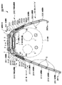
FIG. 1 is a plan view of the wristwatch 100, and FIG. 2 is a front view of the wristwatch 100. 3 is a cross-sectional view taken along the line III-III in FIG. 1, and FIG. 4 is a cross-sectional view showing a state where the wristwatch of FIG. 3 is attached to the wrist. FIG. 5 is an enlarged cross-sectional view of the main body of the wristwatch 100.
As shown in FIGS. 1 and 2, the wristwatch 100 includes a device main body 1 that measures time and measures a pulse, a band 2 that attaches the device main body 1 to a wrist R, and the like.
図3〜図5に示すように、装置本体1には、外側に配され、環状に形成されたケース体3が設けられ、ケース体3の上端部には時計ガラス4が設けられている。ケース体3内部には、時計ガラス4の下方に時刻や脈拍を表示する液晶表示部5が設けられ、液晶表示部5の下面側には、液晶表示部5に結線された時計計時部6が設けられている。また、ケース体3の外面には腕時計100の操作を行う操作キー7が設けられており、操作キー7の一端部はケース体3を貫通して時計計時部6に到達するように設けられている。すなわち、操作キー7を押下することにより、時計計時部6内の所定の回路が接続されて、この回路に対応する動作が実行されるようになっている。時計計時部6の下方には、ケース体3内の空間を仕切る仕切りプレート8が設けられている。仕切りプレート8は、例えば、ステンレス鋼板(SUS鋼板)から成形され、仕切りプレート8の上面側には、時計計時部6を支持する支持部材9が設けられている。また、仕切りプレート8の下面側には、生体情報検出部としての脈拍検出部Pが設けられている。
As shown in FIGS. 3 to 5, the apparatus main body 1 is provided with a
図6は、脈拍検出部Pの拡大断面図、図7は、裏蓋15の断面図、図8は、図5におけるVIII−VIII断面図である。
図6に示すように、脈拍検出部Pには、仕切りプレート8を固定するハウジング10が設けられ、ビス(図示略)によって仕切りプレート8はハウジング10に固着されている。ハウジング10は略円盤状に形成され、ハウジング10の中心から少し外れた位置に中心を有する凹部10aが形成されている。また、この凹部10aの底面の一部にはハウジング10の下面側に貫通する開口部10bが形成されている。さらに、凹部10aの底面には、溝部10cが環状に形成され、この溝部10cには弾性を有するゴム等から成形されたOリング11が設けられている。また、凹部10aの底面には、当該底面のほぼ全域及び開口部10bを覆うように薄型プレート12が設けられている。薄型プレート12は、例えば、ステンレス鋼板(SUS鋼板)から成形されており、仕切りプレート8よりも薄く形成されている。開口部10bに面する薄型プレート12の上面には、手首付近の血管の脈動を検出する圧電素子13が貼り付けられている。また、仕切りプレート8と薄型プレート12との間には、圧電素子13の周囲に空間ができるように形成されたスペーサ14が設けられ、このスペーサ14が仕切りプレート8により押圧されることにより、薄型プレート12を溝部10cに向かって押圧するようになっている。これにより、Oリング11に押圧力が作用して薄型プレート12の上面側と下面側との間の気密が図られるようになっている。なお、スペーサ14は、仕切りプレート8が容易に撓まないように、アクリロニトリルブタジエンスチレン樹脂(ABS樹脂)等の硬質材料から成形することが望ましい。
6 is an enlarged cross-sectional view of the pulse detector P, FIG. 7 is a cross-sectional view of the
As shown in FIG. 6, the pulse detector P is provided with a
ハウジング10の下面側には、ケース体3の内部を遮蔽する裏蓋15が設けられている。
裏蓋15は、腕時計100を装着した際に手首Rに接触する位置に設けられ、装着時の手首R付近の血管の脈動によって弾性変形可能な軟質材料から成形されている。ここで、軟質材料としては、例えば、ウレタンやシリコンを用いることが好ましい。裏蓋15は、押さえ板16によってケース体3に押さえ付けられる固定部15aと、外部に張り出し、装着時に手首Rに接する張出部15bとを備えている。固定部15aには、ケース体3側に突出する突出部15cが裏蓋15の全周に亘って設けられている。そして、裏蓋15をケース体3に固定した際に、突出部15cとケース体3の下端側に形成された凹部3aとが係合して、裏蓋15がずれないように位置決めされるようになっている。
A
The
また、図7に示すように、固定部15aには、突出部15cよりも内側でケース体3側に突出してケース体3に当接する第1の突部15dが形成されている。更に、第1の突部15dの背面側には、押さえ板16側に突出して押さえ板16に当接する第2の突部15eが形成されている。また、固定部15aには、第1の突部15dよりも内側でケース体3側に突出してハウジング10に当接する第3の突部15fが形成されている。
また、張出部15bは、ハウジング10から離間するように下方に張り出して形成され、ハウジング9と張出部15bとの間には気密空間Vが形成されている。
As shown in FIG. 7, the fixed
Further, the overhanging
押さえ板16は、例えば、ステンレス鋼板(SUS鋼板)等の硬質材料から成形され、裏蓋15の固定部15aをケース体3側に裏蓋15を少し変形させる程度、押さえ付けた状態で、ネジ(図示略)によりケース体3に取り付けられている。
この際、ケース体3に当接する第1の突部15dが変形することで、ケース体3と裏蓋15との間の気密が図られる。また、第2の突部15eが変形することで押さえ板16と裏蓋15との間の気密が図られる。さらに、第3の突部15fが変形することで、ハウジング9と裏蓋15との間の気密が図られる。これら、第1の突部15d、第2の突部15e、第3の突部15fとケース体3、裏蓋15、ハウジング10との間で、気密保持が行われる。
The
At this time, the first projecting
また、張出部15bの下面側には、ステンレス鋼板(SUS鋼板)等の硬質材料から成形された硬質プレート17が加硫接着により接着されている。この硬質プレート17は、手首Rから伝達される脈動を張出部15bに均等に作用させる役割を有する。
A hard plate 17 formed of a hard material such as a stainless steel plate (SUS steel plate) is bonded to the lower surface side of the overhanging
図1〜図5に示すように、バンド2は第1のバンド21と第2のバンド22とからなり、ケース体3の中心を挟んで対向する両端部にそれぞれ連結されている。
第1のバンド21には、一端部に設けられ、当該第1のバンド21をケース体3に連結するためのつく部21aと、このつく部21aに隣接して設けられ、第1のバンド21の長手方向に伸縮自在な伸縮部21bと、この伸縮部21bに隣接して設けられ、手首Rに巻きつけられる本体部21cとが備えられている。
つく部21aは、例えば、皮革やウレタン等から成形されており、このつく部21aには、つく棒211aが設けられている。そして、このつく棒211aをケース体3の両端部に形成された孔部に挿通させることにより第1のバンド21をケース体3に連結することができるようになっている。
伸縮部21bは、例えば、ゴム等の弾性材料から成る糸を網目状に縫製したものであり、一端部が縫製によってつく部21aに連結され、他端部が縫製によって本体部21cに連結されている。ここで、伸縮部21bと本体部21cとの連結部C1は、本体部21cの幅方向のみ縫製されるのではなく、例えば、縫製部が凹形状又は凸形状を成すように、本体部21cの幅方向と長手方向とに縫製されることにより、その縫製長さが本体部21cの幅よりも長くなるように縫製されている。また、連結部C1は、超音波・高周波等によってゴムが溶融されており、ゴムの弾性力によって縫製の糸がほどけないような構成となっている。
本体部21cは、例えば、本皮や合皮の皮革、ウレタン等から成形されており、長尺方向に沿って複数の装着孔211cが形成されている。
As shown in FIGS. 1 to 5, the band 2 includes a
The
The tacking
The expansion / contraction part 21b is formed by sewing a thread made of an elastic material such as rubber in a mesh shape, with one end connected to the
The main body portion 21c is formed from, for example, genuine leather, synthetic leather, urethane, or the like, and a plurality of mounting
第2のバンド22には、一端部に設けられ、当該第2のバンド22をケース体3に連結するためのつく部22aと、このつく部22aに隣接して設けられ、第2のバンド22の長手方向に伸縮自在な伸縮部22bと、この伸縮部22bに隣接して設けられ、手首Rに巻きつけられる本体部22cとが備えられている。
つく部22aは、例えば、皮革やウレタン等から成形されており、このつく部22aには、つく棒221aが設けられている。そして、このつく棒221aをケース体3の両端部に形成された孔部に挿通させることにより第2のバンド22をケース体3に連結することができるようになっている。
伸縮部22bは、例えば、ゴム等の弾性材料に対して網目状に縫製したものであり、一端部が縫製によってつく部22aに連結され、他端部が縫製によって本体部22cに連結されている。ここで、伸縮部22bと本体部22cとの連結部C2は、例えば、縫製部が凹形状又は凸形状を成すように、本体部22cの幅方向と長手方向とに縫製されることにより、その縫製長さが本体部22cの幅よりも長くなるように縫製されている。また、連結部C2は、超音波・高周波等によってゴムが溶融されており、ゴムの弾性力によって縫製の糸がほどけないような構成となっている。
本体部22cは、例えば、本皮や合皮の皮革、ウレタン等から成形されており、伸縮部22bと連結される端部の反対側の端部には、美錠221c、装着つく棒222cが設けられている。
The second band 22 is provided at one end, and is provided adjacent to the attaching
The tacking
The stretchable part 22b is, for example, sewn in a mesh shape with respect to an elastic material such as rubber, and one end part is connected to a
The main body 22c is formed from, for example, genuine leather, synthetic leather, urethane, or the like. At the end opposite to the end connected to the expansion / contraction part 22b, a
ケース体3の中心を挟んで対向する両端部には、第1のバンド21及び第2のバンド22の長手方向に延出したカバー部材18が設けられている。図5及び図8に示すように、カバー部材18は、第1のバンド21及び第2のバンド22のつく部21a,22a及び伸縮部21b,22bを囲むような略筒状に形成されている。このカバー部材18のうち、第1のバンド21及び第2のバンド22の裏面側には、つく部21a,22a及び伸縮部21b,22bの裏面側の全域を覆うように延出されたガイド部18aが形成されている。このガイド部18aは、腕時計100を手首Rに装着する際に、伸縮部21b,22bが弾性変形して手首R側に曲がらないように伸縮部21b,22bの伸縮方向を規制する役割を有するものである。
次に、腕時計100を手首Rに装着するときの作用について説明する。
図3、図4に示すように、硬質プレート17を手首Rの甲側に当てて、第1のバンド21及び第2のバンド22を手首Rに沿って巻きつけ、第1のバンド21の先端を第2のバンド22に設けられた美錠221cに挿通させる。この時の動作によって、第1のバンド21及び第2のバンド22には引張力が作用し、伸縮部21b,22bが伸びることとなる。装着者が第1のバンド21及び第2のバンド22を引っ張ると、伸縮部21b,22b、及び本体部21c,22cはつく棒211a,221aを回転中心として回転しつつ、手首Rの裏側付近に向けて引っ張られる。
ここで、伸縮部21b,22bは、カバー部材18のガイド部18aによって回転動作及び伸縮方向が規制され、ガイド部18aに沿って伸びる。また、本体部21c,22cは、手首Rによって回転動作が規制され、手首Rに沿って変形する。
これにより、第1のバンド21及び第2のバンド22は、伸縮部21b,22bが手首Rから遠ざかる方向に伸ばされてから本体部21c,22cが手首に巻回される。そして、装着者は、手首Rの太さや好みに合わせて、第2のバンド22の装着つく棒222cを第1のバンド21の装着孔211cに挿通させる。
その後、装着者が第1のバンド21及び第2のバンド22から手を離すと、伸びた状態の伸縮部21b、22bには、元の状態に復元しようとする復元力が作用し、この復元力によってバンド2が増し締めされる。
Next, an operation when the wristwatch 100 is worn on the wrist R will be described.
As shown in FIGS. 3 and 4, the
Here, the expansion and contraction portions 21 b and 22 b are restricted in rotational operation and expansion and contraction direction by the
As a result, the
Thereafter, when the wearer releases his / her hands from the
次に、腕時計100による脈拍測定の仕組みについて説明する。
図4に示すように、手首Rに腕時計100のケース体3が手の甲側になるようにバンド2で装着した場合、前腕の中の尺骨S及び橈骨Tの近傍を流れる尺骨動脈及び橈骨動脈に直交する方向にバンド2が配されることとなる。なお、前腕にある2本の骨のうち、小指側にある軸状の長骨を尺骨といい、親指側にある軸状の長骨を橈骨という。
Next, the mechanism of pulse measurement by the wristwatch 100 will be described.
As shown in FIG. 4, when the wrist body 100 is attached to the wrist R with the band 2 so that the
各動脈は、脈拍に同期して心臓から送り出される血液の圧力変動により、拡張と収縮を繰り返す。動脈が拡張すると、バンド2は、尺骨S及び橈骨Tに対して拡がる方向に力が作用し、動脈が収縮すると、バンド2は、拡がる方向に作用する力が開放され、戻ろうとする力が働く。このため、バンド2には、張力が作用するときと、張力から開放されるときとが交互に訪れる。この張力変動は、バンド2及びケース体3を介して脈拍検出部Pに伝達されるため、動脈が拡張したときは脈拍検出部Pにはバンド2に作用する張力が伝達され、脈拍検出部Pは手首Rに押し付けられる。
Each artery repeats dilation and contraction due to pressure fluctuations in blood pumped from the heart in synchronization with the pulse. When the artery is expanded, a force is applied to the band 2 in the expanding direction with respect to the ulna S and the radius T, and when the artery is contracted, the force applied in the expanding direction is released and the force to return the band 2 is applied. . For this reason, when the tension acts on the band 2 and when it is released from the tension alternately. Since this tension fluctuation is transmitted to the pulse detector P via the band 2 and the
脈拍検出部Pが手首Rに押し付けられることにより、硬質プレート17を介して裏蓋15がケース体3内部側に弾性変形し、裏蓋15とハウジング10との間に形成された気密空間Vが圧縮される。すると、気密空間V内の空気圧は上昇し、この空気圧が薄型プレート12を押圧する。押圧された薄型プレート12は凹部10a側に撓み、この撓みに伴って圧電素子13も撓む。そして、圧電素子13には、圧電素子13の撓みの大きさに応じた電圧が発生し、この電圧は、電気信号として時計計時部6に送られ、時計計時部6が脈拍を算出して、液晶表示部5に表示させる。
When the pulse detector P is pressed against the wrist R, the
本発明に係る実施形態1の腕時計100によれば、バンド2により装置本体1を手首Rに装着する場合において、バンド2には装着者の操作によって引張力が作用し、この引張力によってバンド2の一部である伸縮部21b,22bが伸び、伸縮部21b,22bが伸びた状態で装置本体1は手首Rに装着される。装置本体1の装着後、装着者がバンド2から手を離すと、伸びた状態の伸縮部21b,22bには、元の状態に復元しようとする復元力が作用し、この復元力によって伸縮部21b,22bは縮むこととなる。伸縮部21b,22bが縮むことにより、バンド2の外周は小さくなるので、バンド2が増し締めされる。これにより、装着者がバンド2を緩く締めた場合であっても、バンド2の増し締めにより装置本体1は手首Rに密着するようになる。
よって、装着者による装置本体1の手首Rへの締め付けの度合いにかかわらず、手首Rに装置本体1を密着させることができ、確実に脈拍を検出することができる。
According to the wristwatch 100 according to the first embodiment of the present invention, when the apparatus main body 1 is attached to the wrist R by the band 2, a tensile force acts on the band 2 by the operation of the wearer. The apparatus main body 1 is attached to the wrist R in a state where the expansion / contraction parts 21b and 22b which are a part of the expansion / contraction part 21b and 22b and 22b are extended. When the wearer removes his / her hand from the band 2 after the apparatus main body 1 is mounted, a restoring force for restoring the original state acts on the stretched portions 21b and 22b. 21b and 22b will shrink. The outer periphery of the band 2 is reduced by the contraction of the stretchable parts 21b and 22b, so that the band 2 is tightened. Thus, even when the wearer loosely tightens the band 2, the apparatus main body 1 comes into close contact with the wrist R due to the additional tightening of the band 2.
Therefore, regardless of the degree of tightening of the apparatus main body 1 to the wrist R by the wearer, the apparatus main body 1 can be brought into close contact with the wrist R, and the pulse can be reliably detected.
また、腕時計100によれば、カバー部材18のガイド部18aは、伸縮部21b,22bの裏側に設けられ、バンド2の長手方向に沿って延びるように形成されているので、装置本体1を手首Rに装着する場合において、バンド2に引張力が作用すると、伸縮部21b,22bは、ガイド部18aによって伸縮方向が規制され、バンド2の長手方向の伸縮が案内される。すなわち、伸縮部21b,22bはバンド2の長手方向に沿ってのみ伸縮することができる。
よって、バンド2は、伸縮部21b,22bがバンド2の長手方向に沿って一旦引っ張られた状態となってから手首Rに締め付けられることとなるので、装置本体1を確実に手首Rに密着した状態で装着させることができ、確実に脈拍を検出することができる。
Further, according to the wristwatch 100, the
Therefore, since the band 2 is tightened to the wrist R after the stretchable parts 21b and 22b are once pulled along the longitudinal direction of the band 2, the apparatus main body 1 is securely adhered to the wrist R. It can be worn in a state, and the pulse can be reliably detected.
さらに、腕時計100によれば、連結部C1,C2の縫製長さを本体部21c,22cの幅よりも長くしたので、連結部C1,C2に引張力等が作用した場合には、本体部21c,22cの幅に沿って縫製した場合に比べて、単位長さ当たりに作用する引張力等は軽減される。よって、連結部C1,C2が破断する限界を高めることができ、連結部C1,C2の耐久性を向上させることができる。 Furthermore, according to the wristwatch 100, since the sewing length of the connecting portions C1 and C2 is longer than the width of the main body portions 21c and 22c, when a tensile force or the like acts on the connecting portions C1 and C2, the main body portion 21c. , 22c, the tensile force acting per unit length is reduced compared to the case of sewing along the width of 22c. Therefore, the limit at which the connecting portions C1 and C2 are broken can be increased, and the durability of the connecting portions C1 and C2 can be improved.
(実施形態2)
次に、本発明に係る腕時計の実施形態2について図9〜図12を用いて説明する。なお、実施形態2の腕時計200が実施形態1の腕時計100と異なる点は、腕時計を手首に装着するためのバンドの構造が異なる点であるため、そのバンドについて説明し、その他の構成要素には同一符号を付して説明を省略する。
図9は、腕時計200の平面図であり、図10は図9におけるX−X断面図であり、図11は図10の腕時計を手首に装着した状態を示す断面図である。図12は図10におけるXII−XII断面図である。
(Embodiment 2)
Next, a second embodiment of the wristwatch according to the present invention will be described with reference to FIGS. The watch 200 of the second embodiment is different from the watch 100 of the first embodiment in that the structure of the band for attaching the watch to the wrist is different. The same reference numerals are given and the description is omitted.
9 is a plan view of the wristwatch 200, FIG. 10 is a sectional view taken along line XX in FIG. 9, and FIG. 11 is a sectional view showing a state in which the wristwatch of FIG. 12 is a cross-sectional view taken along line XII-XII in FIG.
図9〜図11に示すように、腕時計200には、時刻を計時するとともに脈拍測定を行う装置本体1と、この装置本体1を手首Rに装着するバンド20等が備えられている。
バンド20は第1のバンド201と第2のバンド202とからなり、ケース体3の対向する両端部にそれぞれ連結されている。
As shown in FIGS. 9 to 11, the wristwatch 200 includes a device main body 1 that measures time and measures a pulse, a
The
第1のバンド201には、一端部に設けられ、当該第1のバンド201をケース体3に連結するための第1の金属駒2011と、この金属駒2011に隣接して設けられ、第1のバンド201の長手方向に伸縮自在な伸縮部である第2の金属駒としての伸縮金属駒2012と、この伸縮金属駒2012から他端部側に順に連なる第3の金属駒2013、第4の金属駒2014、第5の金属駒2015、第6の金属駒2016、第7の金属駒2017が備えられている。
The first band 201 is provided at one end, and is provided adjacent to the
第1の金属駒2011は、ばね棒2011aを備えており、このばね棒2011aをケース体3の両端部に形成された孔部に挿通させることにより、この第1の金属駒2011をケース体3に連結することができるようになっている。
The
伸縮金属駒2012は、図10〜図12に示すように、第1の金属駒2011に取り付けられる第1の駒部材2012aと、この第1の駒部材2012aにバンド20の長手方向にスライド可能に設けられた第2の駒部材2012bと、第1の駒部材2012aと第2の駒部材2012bとが近づく方向に付勢する伸縮部材としてのコイルばね2012c等を備えている。
第1の駒部材2012aは、図12に示すように、第2の駒部材2012bを囲むような略筒状に形成されている。第1の駒部材2012aには、ストッパーとしてのばね棒2012dが備えられており、第2の駒部材2012bの端部を係止し、第2の駒部材2012bが第1の駒部材2012aから抜け出さないようになっている。
この第1の駒部材2012aと第2の駒部材2012bとの間に配設されたコイルばね2012cにより、第1の駒部材2012aと第2の駒部材2012bとがバンド20の長手方向に伸縮可能となっている。そして、伸縮金属駒2012は、連結する第1の金属駒2011と第3の金属駒2013が互いに近づく方向に付勢するとともに、各金属駒が第1のバンド201の長手方向にスライド可能で伸縮可能となるようにしている。
The telescopic metal piece 2012 is slidable in the longitudinal direction of the
As shown in FIG. 12, the
The
また、第1の駒部材2012aの第1の金属駒2011側にはつく部2121が形成されており、また、第2の駒部材2012bの第3の金属駒2013側にはつく部2122が形成されている。
そして、第1の駒部材2012aのつく部2121に挿通されるばね棒2012eにより、伸縮金属駒2012が第1の金属駒2011に連結される。同様に、第2の駒部材2012bのつく部2122に挿通されるばね棒2012fにより、伸縮金属駒2012が第3の金属駒2013に連結される。
また、第3の金属駒2013から第7の金属駒2017は、連結ねじ19により連結されている。そして、連結する金属駒の数は、装着者の手首の太さに合わせて調節可能になっている。
なお、第7の金属駒2017には、後述する第2のバンド202の第5の金属駒2025の係合突起2025aと係合する係合溝2017aが形成されている。
Further, a sticking
The stretchable metal piece 2012 is connected to the
Further, the
The
第2のバンド202には、一端部に設けられ、当該第2のバンド202をケース体3に連結するための第1の金属駒2021と、この第1の金属駒2021に隣接して設けられ、第2のバンド202の長手方向に伸縮自在な伸縮部である第2の金属駒としての伸縮金属駒2022と、この伸縮金属駒2022から他端部側に順に連なる第3の金属駒2023、第4の金属駒2024、第5の金属駒2025が備えられている。
The second band 202 is provided at one end, and is provided adjacent to the
第1の金属駒2021は、ばね棒2021aを備えており、このばね棒2021aをケース体3の両端部に形成された孔部に挿通させることにより第2のバンド202をケース体3に連結することができるようになっている。
The
伸縮金属駒2022は、図10〜図12に示すように、第1の金属駒2021に取り付けられる第1の駒部材2022aと、第1の駒部材2022aにバンド20の長手方向にスライド可能に設けられた第2の駒部材2022bと、第1の駒部材2022aと第2の駒部材2022bとが近づく方向に付勢する伸縮部材としてのコイルばね2022c等を備えている。
第1の駒部材2022aは、図12に示す第1の駒部材2012aと同様に、第2の駒部材2022bを囲むような略筒状に形成されている。第1の駒部材2022aには、ストッパーとしてのばね棒2022dが備えられており、第2の駒部材2022bの端部を係止し、第2の駒部材2022bが第1の駒部材2022aから抜け出さないようになっている。
この第1の駒部材2022aと第2の駒部材2022bとの間に配設されたコイルばね2022cにより、第1の駒部材2022aと第2の駒部材2022bとがバンド20の長手方向に伸縮可能となっている。そして、伸縮金属駒2022は、連結する第1の金属駒2021と第3の金属駒2023が互いに近づく方向に付勢するとともに、各金属駒が第2のバンド202の長手方向にスライド可能で伸縮可能となるようにしている。
As shown in FIGS. 10 to 12, the extendable metal piece 2022 is provided with a
Similar to the
The
また、第1の駒部材2022aの第1の金属駒2021側にはつく部2221が形成されており、また、第2の駒部材2022bの第3の金属駒2023側にはつく部2222が形成されている。
そして、第1の駒部材2022aのつく部2221に挿通されるばね棒2022eにより、伸縮金属駒2022が第1の金属駒2021に連結される。同様に、第2の駒部材2022bのつく部2222に挿通されるばね棒2022fにより、伸縮金属駒2022が第3の金属駒2023に連結される。
また、第3の金属駒2023から第5の金属駒2025は、連結ねじ19により連結されている。そして、連結する金属駒の数は、装着者の手首の太さに合わせて調節可能になっている。
なお、第5の金属駒2025には、第1のバンド201の第7の金属駒2017の係合溝2017aと係合する係合突起2025aが形成されている。
Further, a sticking
The expandable metal piece 2022 is connected to the
Further, the
The
なお、第1のバンド201、第2のバンド202を構成する各金属駒等は、例えば、ステンレス等の金属材料から成形されている。 In addition, each metal piece etc. which comprise the 1st band 201 and the 2nd band 202 are shape | molded from metal materials, such as stainless steel, for example.
ケース体3の中心を挟んで対向する両端部には、第1のバンド201及び第2のバンド202の長手方向に延出したガイド部としてのガイド部材180がそれぞれ設けられている。このガイド部材180は、第1のバンド201及び第2のバンド202の裏面側に位置するように配設されおり、それぞれ第1の金属駒(2011、2021)と伸縮金属駒(2012,2022)の裏面側の全域を覆うように形成されている。このガイド部材180は、腕時計200を手首Rに装着する際に、第1の金属駒(2011、2021)と伸縮金属駒(2012,2022)との間の連結箇所付近において、バンド20(第1のバンド201、第2のバンド202)が手首R側に近接しないように、その第1の金属駒(2011、2021)と伸縮金属駒(2012,2022)との連結箇所の屈曲方向を規制する役割を有する。
次に、腕時計200を手首Rに装着するときの作用について説明する。
図10、図11に示すように、硬質プレート17を手首Rの甲側に当てて、第1のバンド201及び第2のバンド202を手首Rに沿って巻きつけ、第2のバンド202の第5の金属駒2025の係合突起2025aを、第1のバンド201の第7の金属駒2017の係合溝2017aと係合させる。この時の動作によって、第1のバンド201及び第2のバンド202には引張力が作用し、それぞれの伸縮金属駒2012、2022が伸びることとなる。そして、伸びた状態の伸縮金属駒2012、2022には、元の状態に復元しようとする復元力が作用し、この復元力によってバンド20が増し締めされる。
このバンド20の伸縮金属駒2012、2022が縮む方向に力を作用させることにより、装置本体1の硬質プレート17が、手首Rに向けて押し当てられる。特に、ガイド部材180が、第1の金属駒(2011、2021)と伸縮金属駒(2012,2022)との連結箇所の屈曲方向を好適に規制することにより、硬質プレート17の面が、手首Rに対する付勢方向に対して垂直に押し当てられる。
Next, an operation when the wristwatch 200 is worn on the wrist R will be described.
As shown in FIGS. 10 and 11, the hard plate 17 is placed on the back side of the wrist R, the first band 201 and the second band 202 are wound around the wrist R, and the second band 202 The
The hard plate 17 of the apparatus main body 1 is pressed against the wrist R by applying a force in the direction in which the stretchable metal pieces 2012 and 2022 of the
本発明に係る実施形態2の腕時計200によれば、バンド20により装置本体1を手首Rに装着する場合において、バンド20には装着者の操作によって引張力が作用し、この引張力によってバンド20の一部である伸縮金属駒2012、2022が伸び、伸縮金属駒2012、2022が伸びた状態で装置本体1は手首Rに装着される。装置本体1の装着後、装着者がバンド20から手を離すと、伸びた状態の伸縮金属駒2012、2022には、元の状態に復元しようとする復元力が作用し、この復元力によって伸縮金属駒2012、2022は縮むこととなる。伸縮金属駒2012、2022が縮むことにより、バンド20の外周は小さくなるので、バンド20が増し締めされる。これにより、装着者がバンド20を緩く締めた場合であっても、バンド20の増し締めにより装置本体1は手首Rに密着するようになる。
よって、装着者による装置本体1の手首Rへの締め付けの度合いにかかわらず、手首Rに装置本体1を密着させることができ、確実に脈拍を検出することができる。
According to the wristwatch 200 of the second embodiment of the present invention, when the apparatus main body 1 is attached to the wrist R by the
Therefore, regardless of the degree of tightening of the apparatus main body 1 to the wrist R by the wearer, the apparatus main body 1 can be brought into close contact with the wrist R, and the pulse can be reliably detected.
また、腕時計200によれば、ガイド部材180は、バンド20における第1の金属駒(2011、2021)と伸縮金属駒(2012,2022)の裏面側に設けられ、第1の金属駒(2011、2021)と伸縮金属駒(2012,2022)との連結箇所の屈曲方向を好適に規制するようになっており、装置本体1の硬質プレート17の面が、手首Rに対する付勢方向に対して垂直に押し当てられるので、装置本体1を確実に手首Rに密着した状態で装着させることができ、確実に脈拍を検出することができる。
Further, according to the wristwatch 200, the
(実施形態3)
次に、本発明に係る腕時計の実施形態3について図13〜図15を用いて説明する。なお、実施形態3の腕時計300が実施形態1の腕時計100と異なる点は、腕時計を手首に装着するためのバンドの構造が異なる点であるため、そのバンドについて説明し、その他の構成要素には同一符号を付して説明を省略する。
図13は、腕時計300の平面図であり、図14は図13におけるXIV−XIV断面図であり、図15は図14の腕時計を手首に装着した状態を示す断面図である。
(Embodiment 3)
Next, a third embodiment of the wristwatch according to the present invention will be described with reference to FIGS. The wristwatch 300 of the third embodiment is different from the wristwatch 100 of the first embodiment in that the band structure for attaching the wristwatch to the wrist is different. The same reference numerals are given and the description is omitted.
13 is a plan view of the wristwatch 300, FIG. 14 is a cross-sectional view taken along the line XIV-XIV in FIG. 13, and FIG. 15 is a cross-sectional view illustrating a state in which the wristwatch of FIG.
図13〜図15に示すように、腕時計300には、時刻を計時するとともに脈拍測定を行う装置本体1と、この装置本体1を手首Rに装着するバンド30等が備えられている。
バンド30は第1のバンド301と第2のバンド302とからなり、ケース体3の対向する両端部にそれぞれ連結されている。
As shown in FIGS. 13 to 15, the wristwatch 300 includes a device main body 1 that measures time and measures a pulse, a band 30 that attaches the device main body 1 to a wrist R, and the like.
The band 30 includes a first band 301 and a second band 302 and is connected to opposite ends of the
第1のバンド301には、一端部に設けられ、当該第1のバンド301をケース体3に連結するための第1の金属駒3011、この金属駒3011に隣接して設けられる樹脂駒3012a,3012b、この樹脂駒3012a、3012bから他端部側に順に連なる金属駒3013、樹脂駒3014a,3014b、金属駒3015、樹脂駒3016a,3016b、金属駒3017、樹脂駒3018a,3018b、金属駒3019、樹脂駒3020a,3020b、係合金属駒3001が備えられている。
各金属駒は、例えば、ステンレス等の金属材料から成形されている。
また、各樹脂駒は、例えば、シリコン、NBR、EPDM等の伸縮自在な樹脂、伸縮材料から成形されており、特に、樹脂駒は、第1のバンド301の長手方向に伸縮自在となっている。
The first band 301 is provided at one end, a
Each metal piece is formed from a metal material such as stainless steel, for example.
Each resin piece is formed from, for example, a stretchable resin such as silicon, NBR, or EPDM, or a stretchable material. In particular, the resin piece is stretchable in the longitudinal direction of the first band 301. .
第1の金属駒3011は、ばね棒3011aを備えており、このばね棒3011aをケース体3の両端部に形成された孔部に挿通させることにより第1のバンド301をケース体3に連結することができるようになっている。
The
各金属駒は、第1のバンド301の幅方向の中央側に、第1のバンド301の長手方向に突出する突出部33を有している。そして、近接する金属駒の突出部33を第1のバンド301の幅方向に挟むように、一対の樹脂駒が配設されている。そして、各金属駒の突出部33に形成された貫通孔と、各樹脂駒に形成された貫通孔を連通するように、連結ピン190が挿通されて、金属駒と一対の樹脂駒とが連結されている。
このように、第1の金属駒3011から、樹脂駒3012a,3012b、金属駒3013、樹脂駒3014a,3014b、金属駒3015、樹脂駒3016a,3016b、金属駒3017、樹脂駒3018a,3018b、金属駒3019、樹脂駒3020a,3020b、係合金属駒3001までが、連結ピン190により連結されている。そして、連結する金属駒、樹脂駒の数は、装着者の手首の太さに合わせて調節可能になっている。
なお、係合金属駒3001には、後述する第2のバンド302の係合金属駒3002の係合突起3002aと係合する係合溝3001aが形成されている。
Each metal piece has a projecting
Thus, from the
The
第2のバンド302には、一端部に設けられ、当該第2のバンド302をケース体3に連結するための第1の金属駒3021、この金属駒3021に隣接して設けられる樹脂駒3022a,3022b、この樹脂駒3022a、3022bから他端部側に順に連なる金属駒3023、樹脂駒3024a,3024b、金属駒3025、樹脂駒3026a,3026b、係合金属駒3002が備えられている。
各金属駒は、例えば、ステンレス等の金属材料から成形されている。
また、各樹脂駒は、例えば、シリコン、NBR、EPDM等の伸縮自在な樹脂、伸縮材料から成形されており、特に、樹脂駒は、第2のバンド302の長手方向に伸縮自在となっている。
The second band 302 is provided at one end, a
Each metal piece is formed from a metal material such as stainless steel, for example.
Each resin piece is formed from, for example, a stretchable resin or stretchable material such as silicon, NBR, or EPDM. In particular, the resin piece is stretchable in the longitudinal direction of the second band 302. .
第1の金属駒3021は、ばね棒3021aを備えており、このばね棒3021aをケース体3の両端部に形成された孔部に挿通させることにより第2のバンド302をケース体3に連結することができるようになっている。
The
各金属駒は、第2のバンド302の幅方向の中央側に、第2のバンド302の長手方向に突出する突出部33を有している。そして、近接する金属駒の突出部33を第2のバンド302の幅方向に挟むように、一対の樹脂駒が配設されている。そして、各金属駒の突出部に形成された貫通孔と、各樹脂駒に形成された貫通孔を連通するように、連結ピン190が挿通されて、金属駒と一対の樹脂駒とを連結している。
このように、第1の金属駒3021から、樹脂駒3022a,3022b、金属駒3023、樹脂駒3024a,3024b、金属駒3025、樹脂駒3026a,3026b、係合金属駒3002までが、連結ピン190により連結されている。そして、連結する金属駒、樹脂駒の数は、装着者の手首の太さに合わせて調節可能になっている。
なお、係合金属駒3002には、第1のバンド301の係合金属駒3001の係合溝3001aと係合する係合突起3002aが形成されている。
Each metal piece has a projecting
In this way, the
The engaging
ケース体3の中心を挟んで対向する両端部には、第1のバンド301及び第2のバンド302の長手方向に延出したガイド部としてのガイド部材180がそれぞれ設けられている。このガイド部材180は、第1のバンド301及び第2のバンド302の裏面側に位置するように配設されおり、それぞれ第1の金属駒(3011、3021)と第1の金属駒に隣接する一対の樹脂駒の裏面側の全域を覆うように形成されている。このガイド部材180は、腕時計300を手首Rに装着する際に、第1の金属駒(3011、3021)と隣接する一対の樹脂駒との間の連結箇所付近において、バンド30(第1のバンド301、第2のバンド302)が手首R側に近接しないように、その第1の金属駒と一対の樹脂駒との連結箇所の屈曲方向を規制する役割を有する。
次に、腕時計300を手首Rに装着するときの作用について説明する。
図14、図15に示すように、硬質プレート17を手首Rの甲側に当てて、第1のバンド301及び第2のバンド302を手首Rに沿って巻きつけ、第2のバンド302の係合金属駒3002の係合突起3002aを、第1のバンド301の係合金属駒3001の係合溝3001aと係合させる。この時の動作によって、第1のバンド301及び第2のバンド302には引張力が作用し、それぞれの樹脂駒がバンド30の長手方向に伸びることとなる。そして、伸びた状態の樹脂駒には、元の状態に復元しようとする復元力が作用し、この復元力によってバンド30が増し締めされる。
このバンド30が縮む方向に力を作用させることにより、装置本体1の硬質プレート17が、手首Rに向けて押し当てられる。特に、ガイド部材180が、第1の金属駒(3011、3021)と隣接する一対の樹脂駒との連結箇所の屈曲方向及びを樹脂駒の伸縮方向を好適に規制することにより、硬質プレート17の面が、手首Rに対する付勢方向に対して垂直に押し当てられる。
Next, an operation when the wristwatch 300 is worn on the wrist R will be described.
As shown in FIGS. 14 and 15, the hard plate 17 is placed on the back side of the wrist R, the first band 301 and the second band 302 are wound around the wrist R, and the engagement of the second band 302 is performed. The
By applying a force in the direction in which the band 30 contracts, the hard plate 17 of the apparatus main body 1 is pressed toward the wrist R. In particular, the
本発明に係る実施形態3の腕時計300によれば、バンド30により装置本体1を手首Rに装着する場合において、バンド30には装着者の操作によって引張力が作用し、この引張力によってバンド30の一部である樹脂駒がバンドの長手方向に伸び、樹脂駒が伸びた状態で装置本体1は手首Rに装着される。装置本体1の装着後、装着者がバンド30から手を離すと、伸びた状態の樹脂駒には、元の状態に復元しようとする復元力が作用し、この復元力によって樹脂駒は縮むこととなる。樹脂駒が縮むことにより、バンド30の外周は小さくなるので、バンド30が増し締めされる。これにより、装着者がバンド30を緩く締めた場合であっても、バンド30の増し締めにより装置本体1は手首Rに密着するようになる。
よって、装着者による装置本体1の手首Rへの締め付けの度合いにかかわらず、手首Rに装置本体1を密着させることができ、確実に脈拍を検出することができる。
According to the wristwatch 300 of
Therefore, regardless of the degree of tightening of the apparatus main body 1 to the wrist R by the wearer, the apparatus main body 1 can be brought into close contact with the wrist R, and the pulse can be reliably detected.
また、腕時計300によれば、ガイド部材180は、バンド30における第1の金属駒(3011、3021)とそれに隣接する一対の樹脂駒の裏面側に設けられ、第1の金属駒(3011、3021)とその樹脂駒との連結箇所の屈曲方向を好適に規制するようになっており、装置本体1の硬質プレート17の面が、手首Rに対する付勢方向に対して垂直に押し当てられるので、装置本体1を確実に手首Rに密着した状態で装着させることができ、確実に脈拍を検出することができる。
Further, according to the wristwatch 300, the
(実施形態4)
次に、本発明に係る腕時計の実施形態4について図16、図17を用いて説明する。なお、実施形態4の腕時計400が実施形態1の腕時計100と異なる点は、腕時計を手首に装着するためのバンドの構造が異なる点であるため、そのバンドについて説明し、その他の構成要素には同一符号を付して説明を省略する。
図16及び図17は、腕時計400の断面図である。
(Embodiment 4)
Next, a fourth embodiment of the wristwatch according to the present invention will be described with reference to FIGS. The watch 400 of the fourth embodiment is different from the watch 100 of the first embodiment in that the structure of the band for attaching the watch to the wrist is different. Therefore, the band will be described, and other components will be described. The same reference numerals are given and the description is omitted.
16 and 17 are cross-sectional views of the wristwatch 400. FIG.
図16、図17に示すように、腕時計400には、時刻を計時するとともに脈拍測定を行う装置本体1と、この装置本体1を手首Rに装着するバンド40等が備えられている。
バンド40は第1のバンド401と第2のバンド402とからなり、ケース体3の中心を挟んで対向する両端部にそれぞれ連結されている。
As shown in FIGS. 16 and 17, the wristwatch 400 includes a device main body 1 that measures time and measures a pulse, a band 40 that attaches the device main body 1 to a wrist R, and the like.
The band 40 includes a first band 401 and a second band 402, and is connected to both ends opposed to each other across the center of the
第1のバンド401は、手首Rに巻きつけられる本体部401cと、この本体部401cと一体に形成され、第1のバンド401の一端部に設けられて当該第1のバンド401をケース体3に連結するためのつく部401aとを備えている。
この第1のバンド401の本体部401cは、例えば、シリコン、NBR、EPDM等の伸縮自在な樹脂、伸縮材料から成形されており、特に、第1のバンド401の長手方向に伸縮自在となっている。
また、本体部401cには、その長尺方向に沿って複数の装着孔(図示省略)が形成されている。
つく部401aには、つく棒411aが設けられている。そして、このつく棒411aをケース体3の両端部に形成された孔部に挿通させることにより第1のバンド401をケース体3に連結することができるようになっている。
The first band 401 is formed integrally with the
The
Further, a plurality of mounting holes (not shown) are formed in the
The sticking
第2のバンド402は、手首Rに巻きつけられる本体部402cと、この本体部402cと一体に形成され、第2のバンド402の一端部に設けられて当該第2のバンド402をケース体3に連結するためのつく部402aとを備えている。
この第2のバンド402の本体部402cは、例えば、シリコン、NBR、EPDM等の伸縮自在な樹脂、伸縮材料から成形されており、特に、第2のバンド402の長手方向に伸縮自在となっている。
また、本体部402cにおける、つく部402aとの反対側の端部には、美錠421c、装着つく棒422cが設けられている。
つく部402aには、つく棒412aが設けられている。そして、このつく棒412aをケース体3の両端部に形成された孔部に挿通させることにより第2のバンド402をケース体3に連結することができるようになっている。
The second band 402 is formed integrally with the
The
In addition, a
The sticking
ケース体3の中心を挟んで対向する両端部には、第1のバンド401及び第2のバンド402の長手方向に延出したカバー部材18が設けられている(図5、図8参照)。図5及び図8に示すように、カバー部材18は、バンド40(本体部401c、402c)のつく部401a,402a側を囲むような略筒状に形成されている。このカバー部材18のうち、バンド40の裏面側に位置する部分には、つく部401a,402a側の裏面側を覆うように延出されたガイド部18aが形成されている。このガイド部18aは、腕時計400を手首Rに装着する際に、バンド40のつく部401a,402a側の本体部401c、402cが弾性変形して手首R側に曲がらないように、その変形方向、伸縮方向を規制する役割を有する。
次に、腕時計400を手首Rに装着するときの作用について説明する。
図17に示すように、硬質プレート17を手首Rの甲側に当てて、第1のバンド401及び第2のバンド402を手首Rに沿って巻きつけ、第1のバンド401の先端を第2のバンド402に設けられた美錠421cに挿通させる。この時の動作によって、第1のバンド401及び第2のバンド402には引張力が作用し、本体部401c,402cがその長手方向に伸びることとなる。装着者が第1のバンド401及び第2のバンド402を引っ張ると、本体部401c,402cはつく棒411a,412aを回転中心として回転しつつ、手首Rの裏側付近に向けて引っ張られる。
ここで、第1のバンド401及び第2のバンド402のつく部401a,402a側の本体部401c,402cは、カバー部材18のガイド部18aによって回転動作及び伸縮方向が規制され、ガイド部18aに沿って伸びる。また、本体部401c,402cは、手首Rによって回転動作が規制され、手首Rに沿って変形する。
これにより、第1のバンド401及び第2のバンド402は、本体部401c,402cが手首Rから遠ざかる方向に伸ばされてから手首Rに巻回される。そして、装着者は、手首Rの太さや好みに合わせて、装着つく棒422cを第1のバンド401の装着孔(図示省略)に挿通させる。
その後、装着者が第1のバンド401と第2のバンド402から手を離すと、伸びた状態の本体部401c,402cには、元の状態に復元しようとする復元力が作用し、この復元力によってバンド40が増し締めされる。
そして、このバンド40(本体部401c、402c)が縮む方向に力を作用させることにより、装置本体1の硬質プレート17が、手首Rに向けて押し当てられる。特に、カバー部材18(ガイド部18a)が、バンド40のつく部401a,402a側の本体部401c、402cの変形方向、伸縮方向を好適に規制することにより、硬質プレート17の面が、手首Rに対する付勢方向に対して垂直に押し当てられる。
Next, an operation when the wristwatch 400 is worn on the wrist R will be described.
As shown in FIG. 17, the hard plate 17 is placed on the back side of the wrist R, the first band 401 and the second band 402 are wound along the wrist R, and the tip of the first band 401 is moved to the second side. Is inserted into a
Here, the
As a result, the first band 401 and the second band 402 are wound around the wrist R after the
Thereafter, when the wearer releases his / her hands from the first band 401 and the second band 402, a restoring force for restoring the original state acts on the
The hard plate 17 of the apparatus main body 1 is pressed against the wrist R by applying a force in a direction in which the band 40 (
本発明に係る実施形態4の腕時計400によれば、バンド40により装置本体1を手首Rに装着する場合において、バンド40には装着者の操作によって引張力が作用し、この引張力によってバンド40の本体部401c、402cがバンド40の長手方向に伸び、本体部401c、402cが伸びた状態で装置本体1は手首Rに装着される。装置本体1の装着後、装着者がバンド40から手を離すと、伸びた状態の本体部401c、402cには、元の状態に復元しようとする復元力が作用し、この復元力によって本体部401c、402cは縮むこととなる。本体部401c、402cが縮むことにより、バンド40の外周は小さくなるので、バンド40が増し締めされる。これにより、装着者がバンド40を緩く締めた場合であっても、バンド40の増し締めにより装置本体1は手首Rに密着するようになる。
よって、装着者による装置本体1の手首Rへの締め付けの度合いにかかわらず、手首Rに装置本体1を密着させることができ、確実に脈拍を検出することができる。
According to the wristwatch 400 according to the fourth embodiment of the present invention, when the apparatus main body 1 is attached to the wrist R by the band 40, a tensile force acts on the band 40 by the operation of the wearer. The apparatus body 1 is attached to the wrist R with the
Therefore, regardless of the degree of tightening of the apparatus main body 1 to the wrist R by the wearer, the apparatus main body 1 can be brought into close contact with the wrist R, and the pulse can be reliably detected.
また、腕時計400によれば、カバー部材18のガイド部18aは、バンド40におけるバンド40のつく部401a,402a側の本体部401c、402cの裏面側に設けられ、バンド40のつく部401a,402a側の本体部401c、402cの変形方向、伸縮方向を好適に規制するようになっており、装置本体1の硬質プレート17の面が、手首Rに対する付勢方向に対して垂直に押し当てられるので、装置本体1を確実に手首Rに密着した状態で装着させることができ、確実に脈拍を検出することができる。
Further, according to the wristwatch 400, the
(実施形態5)
次に、本発明に係る腕時計の実施形態5について図18、図19を用いて説明する。なお、実施形態5の腕時計500が実施形態1の腕時計100と異なる点は、腕時計を手首に装着するためのバンドの構造が異なる点であるため、そのバンドについて説明し、その他の構成要素には同一符号を付して説明を省略する。
図18及び図19は、腕時計500の断面図である。
(Embodiment 5)
Next, a fifth embodiment of the wristwatch according to the present invention will be described with reference to FIGS. The watch 500 of the fifth embodiment is different from the watch 100 of the first embodiment in that the structure of the band for attaching the wrist watch to the wrist is different. The same reference numerals are given and the description is omitted.
18 and 19 are cross-sectional views of the wristwatch 500. FIG.
図18、図19に示すように、腕時計500には、時刻を計時するとともに脈拍測定を行う装置本体1、この装置本体1を手首Rに装着するバンド50等が備えられている。
バンド50は第1のバンド501と第2のバンド502とからなり、ケース体3の中心を挟んで対向する両端部にそれぞれ連結されている。
As shown in FIGS. 18 and 19, the wristwatch 500 includes a device main body 1 that measures time and measures a pulse, a band 50 that attaches the device main body 1 to the wrist R, and the like.
The band 50 includes a first band 501 and a second band 502, and is connected to both ends facing each other across the center of the
第1のバンド501は、手首Rに巻きつけられる本体部501cと、この本体部501cと一体に形成され、第1のバンド501の一端部に設けられて当該第1のバンド501をケース体3に連結するためのつく部501aと、を備えている。
この第1のバンド501の本体部501cは、例えば、ウレタン等から成形されており、その長尺方向に沿って複数の装着孔(図示省略)が形成されている。また、本体部501cにおけるつく部501a側には、伸縮部としての波形状部501bが形成されている。
波形状部501bは、第1のバンド501の本体部501cの長手方向に沿って凹部および凸部が連続する波形状に形成されており、その波形状部分が弾性変形することにより、第1のバンド501の長手方向に伸縮自在となっている。つまり、第1のバンド501自体は、伸縮性の材料でなくとも、波形状部分を形成することにより、第1のバンド501が伸縮性を有するようになっている。
つく部501aには、つく棒511aが設けられている。そして、このつく棒511aをケース体3の両端部に形成された孔部に挿通させることにより第1のバンド501をケース体3に連結することができるようになっている。
The first band 501 is formed integrally with the
The
The
The sticking
第2のバンド502は、手首Rに巻きつけられる本体部502cと、この本体部502cと一体に形成され、第2のバンド502の一端部に設けられて当該第2のバンド502をケース体3に連結するためのつく部502aとを備えている。
この第2のバンド502の本体部502cは、例えば、ウレタン等から成形されており、その本体部502cにおける、つく部502aとの反対側の端部には、美錠521c、装着つく棒522cが設けられている。また、本体部502cにおけるつく部502a側には、伸縮部としての波形状部502bが形成されている。
波形状部502bは、第2のバンド502の本体部502cの長手方向に沿って凹部および凸部が連続する波形状に形成されており、その波形状部分が弾性変形することにより、第2のバンド502の長手方向に伸縮自在となっている。つまり、第2のバンド502自体は、伸縮性の材料でなくとも、波形状部分を形成することにより、第2のバンド502が伸縮性を有するようになっている。
つく部502aには、つく棒512aが設けられている。そして、このつく棒512aをケース体3の両端部に形成された孔部に挿通させることにより第2のバンド502をケース体3に連結することができるようになっている。
The second band 502 is formed integrally with the
The
The
The
ケース体3の中心を挟んで対向する両端部には、第1のバンド501及び第2のバンド502の長手方向に延出したカバー部材18が設けられている(図5、図8参照)。図5及び図8に示すように、カバー部材18は、バンド50(本体部501c、502c)のつく部501a,502a側を囲むような略筒状に形成されている。このカバー部材18のうち、バンド50の裏面側に位置する部分には、つく部501a,502a側の裏面側を覆うように延出されたガイド部18aが形成されている。このガイド部18aは、腕時計500を手首Rに装着する際に、第1のバンド501及び第2のバンド502の波形状部501b,502bが弾性変形して手首R側に曲がらないように、その変形方向、伸縮方向を規制する役割を有する。
次に、腕時計500を手首Rに装着するときの作用について説明する。
図19に示すように、硬質プレート17を手首Rの甲側に当てて、第1のバンド501及び第2のバンド502を手首Rに沿って巻きつけ、第1のバンド501の先端を第2のバンド502に設けられた美錠521cに挿通させる。この時の動作によって、第1のバンド501及び第2のバンド502には引張力が作用し、波形状部501b,502bが弾性変形し、その長手方向に伸びることとなる。装着者が第1のバンド501及び第2のバンド502を引っ張ると、本体部501c,502cはつく棒511a,512aを回転中心として回転しつつ、手首Rの裏側付近に向けて引っ張られる。
ここで、第1のバンド501及び第2のバンド502の波形状部501b,501bは、カバー部材18のガイド部18aによって回転動作及び伸縮方向が規制され、ガイド部18aに沿って伸びる。また、本体部501c,502cは、手首Rによって回転動作が規制され、手首Rに沿って変形する。
これにより、第1のバンド501及び第2のバンド502は、波形状部501b、502bが手首Rから遠ざかる方向に伸ばされてから手首Rに巻回される。そして、装着者は、手首Rの太さや好みに合わせて、装着つく棒522cを第1のバンド501の装着孔(図示省略)に挿通させる。
その後、装着者が第1のバンド501及び第2のバンド502から手を離すと、伸びた状態の波形状部501b,502bには、元の状態に復元しようとする復元力が作用し、この復元力によってバンド50が増し締めされる。
そして、この第1のバンド501及び第2のバンド502の波形状部501b,502bが縮む方向に力を作用させることにより、装置本体1の硬質プレート17が、手首Rに向けて押し当てられる。特に、カバー部材18(ガイド部18a)が、バンド50の波形状部501b,502bの変形方向、伸縮方向を好適に規制することにより、硬質プレート17の面が、手首Rに対する付勢方向に対して垂直に押し当てられる。
Next, an operation when the wristwatch 500 is worn on the wrist R will be described.
As shown in FIG. 19, the hard plate 17 is placed on the back side of the wrist R, the first band 501 and the second band 502 are wound around the wrist R, and the tip of the first band 501 is second Are inserted into a
Here, the wave-shaped
As a result, the first band 501 and the second band 502 are wound around the wrist R after the
Thereafter, when the wearer releases his / her hands from the first band 501 and the second band 502, a restoring force for restoring the original state acts on the expanded
The hard plate 17 of the apparatus main body 1 is pressed toward the wrist R by applying a force in a direction in which the
本発明に係る実施形態5の腕時計500によれば、バンド50により装置本体1を手首Rに装着する場合において、バンド50には装着者の操作によって引張力が作用し、この引張力によってバンド50の波形状部501b,502bがバンドの長手方向に伸び、波形状部501b,502bが伸びた状態で装置本体1は手首Rに装着される。装置本体1の装着後、装着者がバンド50から手を離すと、伸びた状態の波形状部501b,502bには、元の状態に復元しようとする復元力が作用し、この復元力によって波形状部501b,502bは縮むこととなる。波形状部501b,502bが縮むことにより、バンド50の外周は小さくなるので、バンド50が増し締めされる。これにより、装着者がバンド50を緩く締めた場合であっても、バンド50の増し締めにより装置本体1は手首Rに密着するようになる。
よって、装着者による装置本体1の手首Rへの締め付けの度合いにかかわらず、手首Rに装置本体1を密着させることができ、確実に脈拍を検出することができる。
According to the wristwatch 500 of the fifth embodiment of the present invention, when the apparatus main body 1 is attached to the wrist R by the band 50, a tensile force acts on the band 50 by the operation of the wearer, and the band 50 is caused by this tensile force. The apparatus main body 1 is attached to the wrist R in a state where the
Therefore, regardless of the degree of tightening of the apparatus main body 1 to the wrist R by the wearer, the apparatus main body 1 can be brought into close contact with the wrist R, and the pulse can be reliably detected.
また、腕時計500によれば、カバー部材18(ガイド部18a)は、バンド50におけるバンド50の波形状部501b,502bの裏面側に設けられ、バンド50の波形状部501b,502bの変形方向、伸縮方向を好適に規制するようになっており、装置本体1の硬質プレート17の面が、手首Rに対する付勢方向に対して垂直に押し当てられるので、装置本体1を確実に手首Rに密着した状態で装着させることができ、確実に脈拍を検出することができる。
Further, according to the wristwatch 500, the cover member 18 (guide
(実施形態6)
次に、本発明に係る腕時計の実施形態6について図20を用いて説明する。なお、実施形態6の腕時計が実施形態1の腕時計100と異なる点は、腕時計を手首に装着するためのバンドの構造が異なる点であるため、そのバンドについて説明し、その他の構成要素には同一符号を付して説明を省略する。
図20は、腕時計を手首に装着するためのバンドに備えられるバックル部60の斜視図である。
(Embodiment 6)
Next, a sixth embodiment of the wristwatch according to the present invention will be described with reference to FIG. The wristwatch of the sixth embodiment is different from the wristwatch 100 of the first embodiment in that the structure of the band for attaching the wristwatch to the wrist is different, so that the band will be described and the other components are the same. The reference numerals are attached and the description is omitted.
FIG. 20 is a perspective view of a buckle portion 60 provided in a band for attaching a wrist watch to a wrist.
バックル部60は、例えば、第2のバンド22の本体部22cの伸縮部22bと連結される端部の反対側の端部に備えられる。
バックル部60は、ラチェット部61と係合部62とにより構成されている。
For example, the buckle portion 60 is provided at an end portion on the opposite side of the end portion connected to the expansion / contraction portion 22 b of the main body portion 22 c of the second band 22.
The buckle portion 60 includes a ratchet portion 61 and an engaging portion 62.
ラチェット部61は、その一方の端部61aを後述する係合部62の係合孔62aに挿入するようになっている。また、他方の端部には第2のバンド22の本体部22cの端部を接続するための接続部61bが設けられている。
また、ラチェット部61には、バンドの長手方向に沿って凹部および凸部が連続する凹凸部61cが形成されている。
The ratchet portion 61 has one
Further, the ratchet portion 61 is formed with an uneven portion 61c in which a concave portion and a convex portion are continuous along the longitudinal direction of the band.
係合部62の一方の端部には、ラチェット部61の端部61aが挿入される係合孔62aが形成されている。
また、係合部62には、係合孔62aの軸方向と垂直な方向に弾性変形するフック部62cが形成されており、フック部62cの自由端部側には、係合孔62aの軸方向と垂直な方向に突出する爪部62dが形成されている。
また、係合部62には、フック部62cが弾性変形する方向と垂直な方向に弾性変形するプッシュ部62e,62eが形成されている。このプッシュ部62e,62eが係合部62の中央側に押し込められて弾性変形すると、フック部62cの爪部62dを押し上げ、フック部62cを押し上げるように弾性変形させるようになっている。
また、係合部62の他方の端部には、第1のバンド21の本体部21cの装着孔211cと第2のバンド22を結束するための、美錠62f、装着つく棒62gが設けられている。
そして、少なくともバンドを手首に装着する際には、第2のバンド部22にラチェット部61を備えるとともに、第1のバンド部21に係合部62が、美錠62fや装着つく棒62gにより連結されるようになっている。
An
Further, the engaging portion 62 is formed with a
The engaging portion 62 is formed with
Further, the other end of the engaging portion 62 is provided with a
At least when the band is attached to the wrist, the second band portion 22 is provided with a ratchet portion 61, and the engaging portion 62 is connected to the
次に、バックル部60のラチェット部61と係合部62を接続するときの作用について説明する。
図20に示すように、ラチェット部61の端部61aを係合部62の係合孔62aに挿入すると、ラチェット部61の凹凸部61cの凸部61dが、フック部62cの爪部62dと接触する。さらに、ラチェット部61の端部61aを挿入して押し込むと凸部61dが爪部62dを押し上げるように、フック部62cを弾性変形させる。
そして、爪部62dが凸部61dを越えると、その爪部62dは、凸部61dと凸部61dの間に係合するとともに、ラチェット部61と係合部62とが係合して、バックル部60がロックされる。そして、よりバンドを締め付ける場合には、ラチェット部61の端部61aを係合孔62aに押し込み、チェット部61の端部61aから離れる方向の凸部61dと凸部61dの間に爪部62dを係合させるようにする。
また、バンドの締め付けを緩める場合には、係合部62のプッシュ部62e,62eを係合部62の中央側に押し込み、フック部62c(爪部62d)を押し上げるように弾性変形させる。それにより、爪部62dが凸部61dと凸部61dの間から、その係合が解除されるので、ラチェット部61の端部61aを係合部62の係合孔62aから抜き出す方向に移動させることができ、バンドの締め付けを緩めることができる。
このように、バックル部60は、ラチェット部61と係合部62とにより長さ調整が可能に構成されている。
Next, an effect | action at the time of connecting the ratchet part 61 and the engaging part 62 of the buckle part 60 is demonstrated.
As shown in FIG. 20, when the
When the
Further, when loosening the band, the
As described above, the buckle portion 60 is configured to be adjustable in length by the ratchet portion 61 and the engaging portion 62.
このように、バックル部60はラチェット部61と係合部62とにより長さ調整が可能となっているので、このバックル部60を備えるバンドの長さ調整を行うことができることとなる。
つまり、装着者は、手首Rの太さや好みに合わせてバンドを手首に巻き付けた後でも、バックル部60を調整することにより、バンドの締め付け具合を調整することができる。
よって、装着者が、バンドを手首Rに緩めに巻き付けて腕時計を装着した場合でも、手首Rに装置本体1を付勢して脈拍を検出する際には、バックル部60を調整してバンドを増し締めするようにすることができる。
Thus, since the length of the buckle portion 60 can be adjusted by the ratchet portion 61 and the engaging portion 62, the length of the band including the buckle portion 60 can be adjusted.
That is, the wearer can adjust the tightening degree of the band by adjusting the buckle portion 60 even after the band is wound around the wrist according to the thickness or preference of the wrist R.
Therefore, even when the wearer wraps the band loosely around the wrist R and wears the wristwatch, when the apparatus body 1 is urged to the wrist R to detect the pulse, the buckle 60 is adjusted to adjust the band. It can be tightened.
本発明に係る実施形態6の腕時計によれば、バンドにより装置本体1を手首Rに装着する場合において、バックル部60を調整することにより、バンドの締め付け具合を調整することができる。
よって、装着者が、バンドを手首Rに緩めに巻き付けて腕時計を装着した場合でも、バックル部60のラチェット部61の端部61aを係合部62の係合孔62aに挿入することにより、バンドの外周は小さくなるのでバンドが増し締めされる。これにより、装着者がバンドを緩く締めた場合であっても、バンドの増し締めにより装置本体1は手首Rに密着するようになる。そして、手首Rに装置本体1を密着させることができ、確実に脈拍を検出することができる。
According to the wristwatch of the sixth embodiment of the present invention, when the apparatus main body 1 is attached to the wrist R with a band, the tightening degree of the band can be adjusted by adjusting the buckle portion 60.
Therefore, even when the wearer wraps the band loosely around the wrist R and wears the wristwatch, by inserting the
なお、本実施形態6においては、バックル部60の係合部62に、第1のバンド21の本体部21cの装着孔211cと第2のバンド22を結束するための美錠62fと装着つく棒62gを設けるようにしたが、美錠62fと装着つく棒62gを設けずに、第1のバンド21の本体部21cの端部を接続するための接続部を設けるようにしてもよい。
つまり、第1のバンド21の本体部21cの端部に係合部62を備え、第2のバンド22の本体部22cの端部にラチェット部61を備えるようにし、ラチェット部61と係合部62とを係合させることにより、第1のバンド21と第2のバンド22とを結束し、腕時計を手首Rに装着するようにしてもよい。
In the sixth embodiment, a stick that attaches to the engaging portion 62 of the buckle portion 60 and the
That is, the engagement portion 62 is provided at the end of the main body portion 21c of the
なお、本発明に係る腕時計は、上記実施形態に限られるものではない。例えば、伸縮部は両方のバンドに設ける必要はなく、何れか一方のバンドに設けていてもよい。また、伸縮部は、バンドの長手方向に沿った長さが伸縮するものであれば、その材料、構造を問わない。また、バンドの一部をガイド部材として形成してもよい。また、伸縮部と本体部との連結方法も、縫製に限られるものではなく、融着等であってもよい。 The wristwatch according to the present invention is not limited to the above embodiment. For example, the stretchable part need not be provided in both bands, and may be provided in any one of the bands. In addition, the stretchable part may be of any material and structure as long as the length along the longitudinal direction of the band is stretchable. Moreover, you may form a part of band as a guide member. Moreover, the connection method of an expansion-contraction part and a main-body part is not restricted to sewing, Fusion etc. may be sufficient.
また、ガイド部は、ガイド部材として別個の部材として取り付けてもよいし、或いは、装置本体とバンドを連結する連結するカバー部材を設けて、そのカバー部材の裏面側を長手方向に延出させてガイド部を構成してもよい。 The guide portion may be attached as a separate member as the guide member, or a cover member for connecting the apparatus main body and the band is provided, and the back side of the cover member is extended in the longitudinal direction. You may comprise a guide part.
また、金属駒や樹脂駒の形状や数も任意であり、その他、具体的な細部構造等についても適宜に変更可能であることは勿論である。 Also, the shape and number of the metal pieces and the resin pieces are arbitrary, and it is needless to say that other specific detailed structures can be appropriately changed.
1 装置本体
18 カバー部材
18a ガイド部
180 ガイド部材(ガイド部)
2、20、30、40、50 バンド
21、201、301、401、501 第1のバンド
22、202、302、402、502 第2のバンド
21b,22b 伸縮部
21c,22c 本体部
2011、2013、2014、2015、2016、2017、2021、2023 、2024、2025 金属駒
2012、2022 伸縮金属駒
2012a、2022a 第1の駒部材
2012b、2022b 第2の駒部材
2012c、2022c コイルばね(伸縮部材)
3011、3013、3015、3017、3019、3001、3021、3023 、3025、3002 金属駒(定形駒)
3012a,3012b、3014a,3014b、3016a,3016b、301 8a,3018b、3020a,3020b、3022a,3022b、3024a, 3024b、3026a,3026b 樹脂駒(伸縮駒)
401c,402c 本体部
501c,502c 本体部
501b,502b 波形状部(伸縮部、波形状部分)
60 バックル部
61 ラチェット部
61c 凹凸部
62 係合部
62c フック部
62e プッシュ部
100、200、300、400、500 腕時計(生体情報測定装置)
C1,C2 連結部
P 脈拍検出部(生体情報検出部)
R 手首
DESCRIPTION OF SYMBOLS 1 Apparatus
2, 20, 30, 40, 50
3011, 3013, 3015, 3017, 3019, 3001, 3021, 3023, 3025, 3002 Metal piece (standard piece)
3012a, 3012b, 3014a, 3014b, 3016a, 3016b, 3018a, 3018b, 3020a, 3020b, 3022a, 3022b, 3024a, 3024b, 3026a, 3026b Resin piece (expandable piece)
401c, 402c
60 Buckle part 61 Ratchet part 61c Concavity and convexity part 62
C1, C2 connecting part P Pulse detecting part (biological information detecting part)
R wrist
Claims (2)
この生体情報検出部を有する装置本体を手首に装着するバンドと、を備え、
前記装置本体を、前記バンドを介して手首に装着した際において、前記生体情報検出部が前記脈動を検出するように、前記バンドの長手方向に伸縮自在な伸縮部を前記バンドの少なくとも一部に設けており、
前記伸縮部は、縫製により前記バンドの本体部と連結し、前記伸縮部と前記本体部との連結部の縫製長さは、前記本体部の幅よりも長く形成されており、
前記バンドの裏側には、当該バンドの前記手首の内側への移動を規制するガイド部を備えていることを特徴とする生体情報測定装置。 A biological information detector that detects biological information based on the pulsation of an artery near the wrist;
A band for mounting the apparatus main body having the biological information detection unit on the wrist,
When the apparatus main body is attached to the wrist via the band, an expansion / contraction part that can expand and contract in the longitudinal direction of the band is formed on at least a part of the band so that the biological information detection unit detects the pulsation. set only and,
The elastic part is connected to the main body part of the band by sewing, and the sewing length of the connecting part between the elastic part and the main body part is longer than the width of the main body part,
A biological information measuring apparatus comprising a guide portion for restricting movement of the band to the inside of the wrist on the back side of the band .
前記装置本体の中心を挟んで前記一方の端部と対向する他方の端部に取り付けられた第2のバンドと、を有し、
前記第1のバンド部と前記第2のバンド部の何れか一方に凹凸部が形成されたラチェット部を備えるとともに、他方に前記ラチェット部の凹凸部と係合する係合部を備え、前記ラチェット部と前記係合部とにより長さ調整が可能なバックル部が構成されることを特徴とする請求項1記載の生体情報測定装置。
The band includes a first band part attached to one end of the apparatus main body,
A second band attached to the other end facing the one end across the center of the apparatus body,
The ratchet includes a ratchet portion having a concavo-convex portion formed on one of the first band portion and the second band portion, and an engaging portion that engages with the concavo-convex portion of the ratchet portion on the other side. The biological information measuring device according to claim 1, wherein a buckle portion capable of adjusting a length is configured by the portion and the engaging portion.
Priority Applications (1)
| Application Number | Priority Date | Filing Date | Title |
|---|---|---|---|
| JP2009289230A JP4862939B2 (en) | 2009-12-21 | 2009-12-21 | Biological information measuring device |
Applications Claiming Priority (1)
| Application Number | Priority Date | Filing Date | Title |
|---|---|---|---|
| JP2009289230A JP4862939B2 (en) | 2009-12-21 | 2009-12-21 | Biological information measuring device |
Related Parent Applications (1)
| Application Number | Title | Priority Date | Filing Date |
|---|---|---|---|
| JP2004013232A Division JP4487574B2 (en) | 2004-01-21 | 2004-01-21 | Biological information measuring device |
Publications (2)
| Publication Number | Publication Date |
|---|---|
| JP2010110634A JP2010110634A (en) | 2010-05-20 |
| JP4862939B2 true JP4862939B2 (en) | 2012-01-25 |
Family
ID=42299644
Family Applications (1)
| Application Number | Title | Priority Date | Filing Date |
|---|---|---|---|
| JP2009289230A Expired - Lifetime JP4862939B2 (en) | 2009-12-21 | 2009-12-21 | Biological information measuring device |
Country Status (1)
| Country | Link |
|---|---|
| JP (1) | JP4862939B2 (en) |
Cited By (1)
| Publication number | Priority date | Publication date | Assignee | Title |
|---|---|---|---|---|
| WO2016161225A1 (en) * | 2015-04-02 | 2016-10-06 | Microsoft Technology Licensing, Llc | Transducing pressure to a non-invasive pulse sensor |
Families Citing this family (4)
| Publication number | Priority date | Publication date | Assignee | Title |
|---|---|---|---|---|
| KR102270209B1 (en) | 2014-10-28 | 2021-06-29 | 삼성전자주식회사 | Wearable electronic device |
| JP2016096955A (en) | 2014-11-20 | 2016-05-30 | セイコーエプソン株式会社 | Biological information measurement apparatus |
| KR101685641B1 (en) * | 2016-06-30 | 2016-12-12 | 신민철 | Smart band for putting on ankle |
| DE212019000028U1 (en) * | 2019-08-07 | 2019-11-04 | Suzhou Kangfu Intelligent Technology Co., Ltd. | A portable flexible sensor device |
Family Cites Families (4)
| Publication number | Priority date | Publication date | Assignee | Title |
|---|---|---|---|---|
| JPS6020012B2 (en) * | 1983-01-19 | 1985-05-20 | メドトロニック・インコ−ポレ−テッド | heart rate monitoring device |
| JPH02141208A (en) * | 1988-11-22 | 1990-05-30 | Ushio Yuutec:Kk | Takeoff apparatus for molding article |
| JPH05329117A (en) * | 1992-05-28 | 1993-12-14 | Sanyo Electric Co Ltd | Band type information detection device |
| JP2001238710A (en) * | 2000-02-28 | 2001-09-04 | Seiko Corp | Band for wrist watch |
-
2009
- 2009-12-21 JP JP2009289230A patent/JP4862939B2/en not_active Expired - Lifetime
Cited By (1)
| Publication number | Priority date | Publication date | Assignee | Title |
|---|---|---|---|---|
| WO2016161225A1 (en) * | 2015-04-02 | 2016-10-06 | Microsoft Technology Licensing, Llc | Transducing pressure to a non-invasive pulse sensor |
Also Published As
| Publication number | Publication date |
|---|---|
| JP2010110634A (en) | 2010-05-20 |
Similar Documents
| Publication | Publication Date | Title |
|---|---|---|
| JP4862939B2 (en) | Biological information measuring device | |
| US4307727A (en) | Wrist band transducer support and tensioning apparatus | |
| US11925443B2 (en) | Blood pressure monitor, blood pressure measurement apparatus and blood pressure measurement method | |
| CN110198661B (en) | Sphygmomanometer, blood pressure measuring method and equipment | |
| US20040193059A1 (en) | Wrist type blood pressure meter cuff | |
| TWI631930B (en) | Physiology signal sensing device | |
| JP2018102859A5 (en) | ||
| US20080275356A1 (en) | Respiratory sensing belt using piezo film | |
| WO2018123372A1 (en) | Sphygmomanometer, blood pressure measurement method, and device | |
| US11298032B2 (en) | Wearable blood pressure measuring device | |
| WO2018123374A1 (en) | Sphygmomanometer, blood pressure measurement method, and device | |
| JP4487574B2 (en) | Biological information measuring device | |
| JP2005204804A (en) | Biological information measuring apparatus | |
| JP2010137110A (en) | Bioinformation measuring instrument | |
| JP2006271610A (en) | Band | |
| JP7077776B2 (en) | Blood pressure measuring device | |
| JP4561112B2 (en) | Biological information measuring device | |
| JP2002159457A (en) | Body-worn measuring device | |
| JP2005342163A (en) | Wrist-worn instrument | |
| JP2010075731A (en) | Bioinformation measuring device | |
| US20200315463A1 (en) | Information processing apparatus, information processing method, and non-transitory computer-readable storage medium | |
| JP2005211301A (en) | Body wearing type measured result display control device and program | |
| CN105700678B (en) | A kind of electronic equipment and detection method | |
| JP3961476B2 (en) | Pressure pulse wave sensor and pressure pulse wave measuring device | |
| CN107518537B (en) | Tightening device and method for operating a tightening device for tightening attachment to an object |
Legal Events
| Date | Code | Title | Description |
|---|---|---|---|
| TRDD | Decision of grant or rejection written | ||
| A01 | Written decision to grant a patent or to grant a registration (utility model) |
Free format text: JAPANESE INTERMEDIATE CODE: A01 Effective date: 20111011 |
|
| A01 | Written decision to grant a patent or to grant a registration (utility model) |
Free format text: JAPANESE INTERMEDIATE CODE: A01 |
|
| A61 | First payment of annual fees (during grant procedure) |
Free format text: JAPANESE INTERMEDIATE CODE: A61 Effective date: 20111024 |
|
| FPAY | Renewal fee payment (event date is renewal date of database) |
Free format text: PAYMENT UNTIL: 20141118 Year of fee payment: 3 |
|
| R150 | Certificate of patent or registration of utility model |
Ref document number: 4862939 Country of ref document: JP Free format text: JAPANESE INTERMEDIATE CODE: R150 Free format text: JAPANESE INTERMEDIATE CODE: R150 |
|
| EXPY | Cancellation because of completion of term |