JP4859250B2 - Distance adjustment apparatus and method for inspection object, inspection apparatus and method - Google Patents
Distance adjustment apparatus and method for inspection object, inspection apparatus and method Download PDFInfo
- Publication number
- JP4859250B2 JP4859250B2 JP2008165175A JP2008165175A JP4859250B2 JP 4859250 B2 JP4859250 B2 JP 4859250B2 JP 2008165175 A JP2008165175 A JP 2008165175A JP 2008165175 A JP2008165175 A JP 2008165175A JP 4859250 B2 JP4859250 B2 JP 4859250B2
- Authority
- JP
- Japan
- Prior art keywords
- distance
- transmission line
- terahertz wave
- inspection object
- unit
- Prior art date
- Legal status (The legal status is an assumption and is not a legal conclusion. Google has not performed a legal analysis and makes no representation as to the accuracy of the status listed.)
- Expired - Fee Related
Links
Images


Description
本発明は、物体(検査物)に関する距離調整装置及び方法、物体(検査物)の検査装置及び方法などに関する。特には、30GHz以上30THz以下の周波数範囲のうちの任意の周波数帯域を有する高周波電磁波(本明細書ではテラヘルツ波とも呼ぶ)を用いて検査物までの距離を調整する距離調整装置及び方法、検査物の検査装置及び検査方法に関する。 The present invention relates to a distance adjustment apparatus and method for an object (inspection object), an inspection apparatus and method for an object (inspection object), and the like. In particular, a distance adjustment apparatus and method for adjusting the distance to an inspection object using a high-frequency electromagnetic wave (also referred to as a terahertz wave in this specification) having an arbitrary frequency band within a frequency range of 30 GHz to 30 THz, and the inspection object The present invention relates to an inspection apparatus and an inspection method.
近年、テラヘルツ波を用いた非破壊なセンシング技術が開発されてきている。この周波数帯の電磁波の応用分野としては、X線に代わる安全な透視検査装置を用いてイメージングを行う技術が開発されている。また、物質内部の吸収スペクトルや複素誘電率を求めて結合状態などの物性を調べる分光技術、生体分子の解析技術、キャリア濃度や移動度を評価する技術なども開発されている。 In recent years, nondestructive sensing technology using terahertz waves has been developed. As an application field of electromagnetic waves in this frequency band, a technique for performing imaging using a safe fluoroscopic inspection apparatus replacing X-rays has been developed. In addition, a spectroscopic technique for obtaining an absorption spectrum and a complex dielectric constant inside a substance and examining physical properties such as a binding state, a biomolecule analysis technique, and a technique for evaluating carrier concentration and mobility have been developed.
テラヘルツ波を用いて物体を検査するための装置が、特許文献1に開示されている。この検査装置は、空間を伝播するテラヘルツ波を物体に照射し、物体からの透過波の伝播状態の変化により物体の構成材料の特性を測定する装置である。この提案においては、物体を2次元走査することで物体内部の透過イメージング像を得ている。 An apparatus for inspecting an object using terahertz waves is disclosed in Patent Document 1. This inspection apparatus is an apparatus that irradiates an object with a terahertz wave propagating in space and measures the characteristics of the constituent material of the object by changing the propagation state of the transmitted wave from the object. In this proposal, a transmission imaging image inside the object is obtained by scanning the object two-dimensionally.
一方、テラヘルツ波は、高周波電磁波信号の伝送に用いられる伝送線路を伝播することが知られている。この特性を利用するために、オンチップ(検査物を伝送線路に乗せること)により、検査物の物性を測定する検査装置が非特許文献1に開示されている。非特許文献1のセンサチップは、テラヘルツ波を発生させるための発生部、マイクロストリップ線路、テラヘルツ波を検出するための検出部がガラス基板上に集積されたものである。非特許文献1は、漏れ電磁界と該マイクロストリップライン上に塗布した水との相互作用によって、テラヘルツ波の強度の減衰と時間波形の遅延を計測している。ここで、漏れ電磁界とは、マイクロストリップラインを伝搬するテラヘルツ波が該マイクロストリップラインから微弱に漏れ出ることにより発生する電磁界のことである。
上述のセンサチップを用いたテラヘルツ波検査システムは、オンチップ計測であるが故に、以下のような課題を抱えている。 The terahertz wave inspection system using the above-described sensor chip has the following problems because it is on-chip measurement.
まず、多量の検査物を高速で計測する用途には向いているとは言えない。例えば、多種多様な生体分子や化学物質などのスクリーニング検査においては、精度と同時に高速性や経済性も求められる。しかしながら、従来のシステムでは、サンプル供給や検査装置へのチップの出し入れなどに工数がかかる為、高速な検査を実現することは容易ではない。 First of all, it cannot be said that it is suitable for the purpose of measuring a large amount of inspection objects at high speed. For example, in screening tests for a wide variety of biomolecules and chemical substances, high speed and economic efficiency are required as well as accuracy. However, in the conventional system, man-hours are required for supplying samples and inserting / withdrawing chips into / from the inspection apparatus, so it is not easy to realize high-speed inspection.
また、多量のサンプルを検査するにはサンプル数に応じたチップ数が必要となるが、一般的にテラヘルツ波の発生及び検出には半導体結晶が用いられることを考慮すれば、チップ数の増加に伴い検査コストが増大することが予想される。 In addition, in order to inspect a large amount of samples, the number of chips corresponding to the number of samples is required. However, in consideration of the fact that semiconductor crystals are generally used for generation and detection of terahertz waves, the number of chips increases. Along with this, the inspection cost is expected to increase.
本発明に係るテラヘルツ波を用いて検査物までの距離を調整するための装置は、
テラヘルツ波を発生させるための発生部、前記テラヘルツ波が伝搬するための伝送線路、前記伝送線路を伝搬するテラヘルツ波を検出するための検出部、を含み構成されるセンサ部と、
前記検出部が検出するタイミングを変えるための遅延部と、
前記遅延部を用いて得る、前記検出部が検出する信号をサンプリングすることにより、時間波形に関する情報を取得するための処理部と、
前記センサ部と前記検査物との距離を変化するための距離変化手段と、を備え、
前記時間波形に関する情報を用いて前記距離を調整することを特徴とする。
An apparatus for adjusting the distance to the inspection object using the terahertz wave according to the present invention,
A sensor unit including a generation unit for generating a terahertz wave, a transmission line for propagating the terahertz wave, and a detection unit for detecting the terahertz wave propagating through the transmission line;
A delay unit for changing the detection timing of the detection unit;
A processing unit for obtaining information on a time waveform by sampling a signal detected by the detection unit, obtained using the delay unit;
A distance changing means for changing a distance between the sensor unit and the inspection object,
The distance is adjusted using information on the time waveform.
また、本発明に係るテラヘルツ波により検査物までの距離を調整するための方法は、
テラヘルツ波が伝搬するための伝送線路と検査物間の第1の距離でテラヘルツ波を発生させる工程と、
前記第1の距離で発生させたテラヘルツ波を該第1の距離で検出する工程と、
前記第1の距離で検出したテラヘルツ波の時間波形に関する情報を取得する工程と、
前記第1の距離よりも短い第2の距離まで、前記伝送線路あるいは検査物を移動する工程と、
前記第2の距離でテラヘルツ波を発生させる工程と、
前記第2の距離で発生させたテラヘルツ波を該第2の距離で検出する工程と、
前記第2の距離で検出したテラヘルツ波の時間波形に関する情報を取得する工程と、
前記第1及び第2の距離で取得した時間波形に関する情報どうしを比較する工程と、
前記時間波形に関する情報の比較結果の変化の有無から、前記伝送線路を伝搬するテラヘルツ波による漏れ電磁界と検査物との相互作用の有無を判断する工程と、
を有することを特徴とする。
In addition, the method for adjusting the distance to the inspection object by the terahertz wave according to the present invention,
Generating a terahertz wave at a first distance between the transmission line and the inspection object for propagating the terahertz wave;
Detecting the terahertz wave generated at the first distance at the first distance;
Obtaining information regarding the time waveform of the terahertz wave detected at the first distance;
Moving the transmission line or inspection object to a second distance shorter than the first distance;
Generating a terahertz wave at the second distance;
Detecting the terahertz wave generated at the second distance at the second distance;
Obtaining information regarding the time waveform of the terahertz wave detected at the second distance;
Comparing the information about the time waveform acquired at the first and second distances;
From the presence or absence of a change in the comparison result of information on the time waveform, determining whether or not there is an interaction between the leakage electromagnetic field caused by the terahertz wave propagating through the transmission line and the inspection object,
It is characterized by having.
また、上記課題に鑑み、本発明の検査装置は、センサ部と、距離調整手段ないし距離変化手段と、を備え、センサ部の伝送線路を伝播するテラヘルツ波と検査物との相互作用の状態を反映するセンサ部の検出部の検出信号に基づき、検査物の情報を取得する。ここにおいて、センサ部は、テラヘルツ波発生部と伝送線路と検出部とを含む。距離調整手段は、テラヘルツ波発生部から発せられ伝送線路を伝播してきたテラヘルツ波を検出する検出部の検出信号に基づき伝送線路と検査物間の距離を調整する。 Further, in view of the above problems, the inspection apparatus of the present invention includes a sensor unit and a distance adjusting unit or a distance changing unit, and the interaction state between the terahertz wave propagating through the transmission line of the sensor unit and the inspection object is determined. Information on the inspection object is acquired based on the detection signal of the detection unit of the sensor unit to be reflected. Here, the sensor unit includes a terahertz wave generation unit, a transmission line, and a detection unit. The distance adjusting means adjusts the distance between the transmission line and the inspection object based on the detection signal of the detection unit that detects the terahertz wave emitted from the terahertz wave generation unit and propagated through the transmission line.
また、上記課題に鑑み、本発明の検査方法は、テラヘルツ波発生部と伝送線路と検出部とを含むセンサを用意するステップと、検査物配置ステップと、粗動ステップと、距離認識ステップと、距離設定ステップと、データ取得ステップと、を含む。ここにおいて、検査物配置ステップでは、センサの伝送線路と対向する位置に、検査物を配置する。粗動ステップでは、テラヘルツ波発生部から発せられ伝送線路を伝播してきたテラヘルツ波を検出する検出部の検出信号をモニタしながら、伝送線路と検査物間の距離を近付ける。距離認識ステップでは、検出部の検出信号の変化から、伝送線路からの漏れ電磁界と検査物の表面とが相互作用を開始する距離を認識する。距離設定ステップでは、前記距離の認識の後に、伝送線路と検査物間の距離を、漏れ電磁界と検査物とが相互作用する目標の距離に設定する。データ取得ステップでは、前記目標の距離に設定した状態において、伝送線路を伝播するテラヘルツ波と検査物との相互作用の状態を反映する検出部の検出信号に基づき、検査物の情報を取得する。 Further, in view of the above problems, the inspection method of the present invention includes a step of preparing a sensor including a terahertz wave generation unit, a transmission line, and a detection unit, an inspection object placement step, a coarse movement step, a distance recognition step, A distance setting step and a data acquisition step are included. Here, in the inspection object placement step, the inspection object is disposed at a position facing the transmission line of the sensor. In the coarse movement step, the distance between the transmission line and the inspection object is brought closer while monitoring the detection signal of the detection unit that detects the terahertz wave emitted from the terahertz wave generation unit and propagated through the transmission line. In the distance recognition step, the distance at which the leakage electromagnetic field from the transmission line and the surface of the inspection object start to interact is recognized from the change in the detection signal of the detection unit. In the distance setting step, after the distance is recognized, the distance between the transmission line and the inspection object is set to a target distance at which the leakage electromagnetic field and the inspection object interact. In the data acquisition step, the information on the inspection object is acquired based on the detection signal of the detection unit that reflects the state of interaction between the terahertz wave propagating through the transmission line and the inspection object in the state set to the target distance.
また、別の本発明に係るテラヘルツ波を用いて検査物までの距離を調整するための装置は、
テラヘルツ波を発生させるための発生部、前記テラヘルツ波が伝搬するための伝送線路、前記伝送線路を伝搬するテラヘルツ波を検出するための検出部、を含み構成されるセンサ部と、
前記センサ部と前記検査物間の距離を変化するための距離変化手段と、を備え、
前記検出部が検出するテラヘルツ波に関する情報を用いて前記距離を調整することを特徴とする。
In addition, an apparatus for adjusting the distance to an inspection object using a terahertz wave according to another present invention,
A sensor unit including a generation unit for generating a terahertz wave, a transmission line for propagating the terahertz wave, and a detection unit for detecting the terahertz wave propagating through the transmission line;
A distance changing means for changing a distance between the sensor unit and the inspection object,
The distance is adjusted using information on the terahertz wave detected by the detection unit.
また、別の本発明に係るテラヘルツ波により検査物までの距離を調整するための方法は、
テラヘルツ波が伝搬するための伝送線路と検査物間の第1の距離でテラヘルツ波を発生させる工程と、
前記第1の距離で発生させたテラヘルツ波を該第1の距離で検出する工程と、
前記第1の距離で検出したテラヘルツ波に関する情報を取得する工程と、
前記第1の距離よりも短い第2の距離まで、前記伝送線路あるいは検査物を移動する工程と、
前記第2の距離でテラヘルツ波を発生させる工程と、
前記第2の距離で発生させたテラヘルツ波を該第2の距離で検出する工程と、
前記第2の距離で検出したテラヘルツ波に関する情報を取得する工程と、
前記第1及び第2の距離で取得したテラヘルツ波に関する情報どうしを比較する工程と、
前記テラヘルツ波に関する情報の比較結果の変化の有無から、前記伝送線路を伝搬するテラヘルツ波による漏れ電磁界と検査物との相互作用の有無を判断する工程と、
を有することを特徴とする。
Further, a method for adjusting the distance to the inspection object by the terahertz wave according to another present invention,
Generating a terahertz wave at a first distance between the transmission line and the inspection object for propagating the terahertz wave;
Detecting the terahertz wave generated at the first distance at the first distance;
Obtaining information on the terahertz wave detected at the first distance;
Moving the transmission line or inspection object to a second distance shorter than the first distance;
Generating a terahertz wave at the second distance;
Detecting the terahertz wave generated at the second distance at the second distance;
Obtaining information about the terahertz wave detected at the second distance;
Comparing the information about the terahertz waves acquired at the first and second distances;
From the presence or absence of a comparison result of information on the terahertz wave, determining whether or not there is an interaction between the leakage electromagnetic field caused by the terahertz wave propagating through the transmission line and the inspection object;
It is characterized by having.
本発明の距離調整装置などによれば、上記の如き距離変化手段ないし距離調整手段を備えるため、伝送線路の漏れ電磁界と検査物とが十分な相互作用を生じる目標の距離まで伝送線路と検査物を近接させことができる。そして、例えば、目標の距離でテラヘルツ波の伝播特性を計測し、検査物の物性などの情報を取得することができる。 According to the distance adjusting device of the present invention, since the distance changing means or the distance adjusting means as described above is provided, the transmission line and the inspection up to the target distance where the leakage electromagnetic field of the transmission line and the test object sufficiently interact with each other. Things can be brought close together. For example, the propagation characteristic of the terahertz wave can be measured at a target distance, and information such as the physical properties of the test object can be acquired.
また、本発明の検査方法によれば、上記検出部の検出信号の変化から、伝送線路から微弱に漏れ出した漏れ電磁界と検査物表面とが相互作用を開始するのを認識することができる。そして、この開始距離は予め概ね分かっているので、この時点で、伝送線路と検査物間の相対的な距離を概ね認識することができる。更に、上記検出信号の変化に基づき、漏れ電磁界と検査物とが十分な相互作用を生じる目標の距離まで伝送線路と検査物を近接させていって、その距離でテラヘルツ波の伝播特性を計測し、検査物の物性などの情報を取得できる。この際、一旦、伝送線路と検査物間の相対的な距離を概ね認識できれば、後は制御された距離ずつ近づけていけばよいので、伝送線路と検査物間の距離を目標の所まで容易且つ確実に持っていくことができる。 Further, according to the inspection method of the present invention, it is possible to recognize that the leakage electromagnetic field leaking weakly from the transmission line and the surface of the inspection object start interaction from the change in the detection signal of the detection unit. . Since the starting distance is generally known in advance, the relative distance between the transmission line and the inspection object can be generally recognized at this point. Furthermore, based on the change in the detection signal, the transmission line and the inspection object are brought close to the target distance where the leakage electromagnetic field and the inspection object have sufficient interaction, and the propagation characteristic of the terahertz wave is measured at that distance. In addition, information such as physical properties of the inspection object can be acquired. At this time, once the relative distance between the transmission line and the inspection object can be generally recognized, the distance between the transmission line and the inspection object can be easily reached to the target. It can be taken with certainty.
本発明の実施形態について、図面を用いて説明する。前述した様に、本明細書では、30GHz以上30THz以下の周波数帯域内の電磁波をテラヘルツ波とも呼ぶ。なお、本発明は、以下の実施形態に係る装置、方法に限定されるものではない。 Embodiments of the present invention will be described with reference to the drawings. As described above, in this specification, an electromagnetic wave in a frequency band of 30 GHz to 30 THz is also referred to as a terahertz wave. In addition, this invention is not limited to the apparatus and method which concern on the following embodiment.
(装置)
本発明の一実施形態に係るテラヘルツ波を用いて距離を調整するための装置について、図9を用いて説明する。まず、901は、テラヘルツ波を発生させるための発生部である。例えば、低温で成長させたガリウムヒ素(LT-GaAs)やインジウムガリウムヒ素(InGaAs)などから成る光伝導膜により構成される。ここで、光伝導膜とは、光が照射されることによりキャリアが発生する膜のことである。なお、発生部901には、共鳴トンネルダイオードやガンダイオードなどの電磁波利得を有する半導体素子を用いることもできる。
(apparatus)
An apparatus for adjusting a distance using a terahertz wave according to an embodiment of the present invention will be described with reference to FIG. First, reference numeral 901 denotes a generator for generating terahertz waves. For example, it is composed of a photoconductive film made of gallium arsenide (LT-GaAs) or indium gallium arsenide (InGaAs) grown at a low temperature. Here, the photoconductive film is a film that generates carriers when irradiated with light. Note that a semiconductor element having electromagnetic wave gain, such as a resonant tunneling diode or a Gunn diode, can also be used for the generation unit 901.
次に、902は、前記発生部901から発生されたテラヘルツ波が伝搬するための伝送線路である。伝送線路902には、金属などの電気伝導性を有する材料から成るマイクロストリップラインなどを適用することができる。また、903は、伝送線路902を伝搬するテラヘルツ波を検出するための検出部である。検出部903には、上記光伝導膜を用いる。なお、検出部903には、ショットキーバリアダイオードなどの検波素子を用いることもできる。ここで、904は、発生部901、伝送線路902、検出部903を含み構成されるセンサ部である。 Next, reference numeral 902 denotes a transmission line through which the terahertz wave generated from the generating unit 901 propagates. As the transmission line 902, a microstrip line made of a material having electrical conductivity such as metal can be used. Reference numeral 903 denotes a detection unit for detecting a terahertz wave propagating through the transmission line 902. The detection unit 903 uses the photoconductive film. Note that a detection element such as a Schottky barrier diode can also be used for the detection unit 903. Here, reference numeral 904 denotes a sensor unit including a generation unit 901, a transmission line 902, and a detection unit 903.
また、905は、前記検出部903が検出するタイミングを変える(遅延する)ための遅延部である。前記遅延部905は、発生部901あるいは検出部903に照射する光の行路を変える手段により構成することができる。 Reference numeral 905 denotes a delay unit for changing (delaying) the timing detected by the detection unit 903. The delay unit 905 can be configured by means for changing the path of light irradiated to the generation unit 901 or the detection unit 903.
ここで、遅延部905の一例として、光学的に遅延する遅延部1005について、図10を用いて説明する。1010は、発生部901及び検出部903にレーザ(光)を照射するためのレーザ照射部である。また、1011は、前記レーザ照射部1010が照射するレーザを分割するためのビームスプリッターである。ビームスプリッター1011で分割されたレーザは、それぞれ、発生部901と検出部903に照射される。発生部901に照射されるレーザは遅延部1005を通過する。遅延部1005には、例えば可動ミラーを用いる。 Here, as an example of the delay unit 905, a delay unit 1005 that optically delays will be described with reference to FIG. Reference numeral 1010 denotes a laser irradiation unit for irradiating the generation unit 901 and the detection unit 903 with laser (light). Reference numeral 1011 denotes a beam splitter for dividing the laser irradiated by the laser irradiation unit 1010. The laser beams split by the beam splitter 1011 are irradiated to the generation unit 901 and the detection unit 903, respectively. The laser irradiated on the generation unit 901 passes through the delay unit 1005. For the delay unit 1005, for example, a movable mirror is used.
また、遅延部905は、前記テラヘルツ波が検出部903に到達する時間を遅延するような構成にすることもできる。テラヘルツ波が伝搬する距離を変えるために、発生部901に照射するレーザの照射位置を変えるような構成にすることもできる。また、テラヘルツ波が伝搬する速度を変えるために、伝搬する領域の屈折率を変えるような構成にすることもできる。 The delay unit 905 may be configured to delay the time for the terahertz wave to reach the detection unit 903. In order to change the distance at which the terahertz wave propagates, it is also possible to change the irradiation position of the laser irradiating the generator 901. Further, in order to change the propagation speed of the terahertz wave, it is possible to change the refractive index of the propagation region.
更に、遅延部905は、電気的に遅延するような構成にすることもできる。例えば、検出したテラヘルツ波の信号とのミキシングをするために発生させる電気信号の時間を遅延するような構成にすることができる。 Further, the delay unit 905 can be configured to be electrically delayed. For example, it is possible to adopt a configuration in which the time of an electric signal generated for mixing with a detected terahertz wave signal is delayed.
また、906は、前記遅延部905を用いて得る、前記検出部903が検出する信号を、サンプリングすることにより時間波形に関する情報を取得するための処理部である。サンプリングに関しては、例えば、前記レーザを照射する周期で行うことができるが、特に限定されるものではない。 Reference numeral 906 denotes a processing unit for acquiring information related to a time waveform by sampling a signal detected by the detection unit 903, which is obtained using the delay unit 905. Sampling can be performed, for example, in the cycle of laser irradiation, but is not particularly limited.
ここで、908は、検査物907を保持するための検査物保持部である。検査物保持部908は、例えば、テフロン(登録商標)やポリイミドなどのポリエチレン樹脂、アルミなどの金属、或いは石英やサファイアなどの無機材料から成る平板にすることができる。後述する内視鏡の例などの場合には、この検査物保持部を省略することもできる。検査物までの距離を良好に調整しやすいように、検査物の特徴に応じて、検査物保持部を設けたり省略したりすればよい。更に、909は、前記センサ部904と前記検査物保持部908あるいは検査物907との距離を変化するための距離変化手段(Z軸ステージ)である。前記距離変化手段には、圧電素子などを用いることができる。ただし、これに限定されるものではない。前記処理部906が取得した前記時間波形に関する情報を用いて前記距離変化手段909を動作させることにより、前記距離を調整する。 Here, reference numeral 908 denotes an inspection object holding unit for holding the inspection object 907. The inspection object holding unit 908 can be a flat plate made of, for example, a polyethylene resin such as Teflon (registered trademark) or polyimide, a metal such as aluminum, or an inorganic material such as quartz or sapphire. In the case of an endoscope to be described later, this inspection object holding unit can be omitted. In order to easily adjust the distance to the inspection object, the inspection object holder may be provided or omitted depending on the characteristics of the inspection object. Further, reference numeral 909 denotes distance changing means (Z-axis stage) for changing the distance between the sensor unit 904 and the inspection object holding unit 908 or the inspection object 907. A piezoelectric element etc. can be used for the distance changing means. However, it is not limited to this. The distance is adjusted by operating the distance changing means 909 using information on the time waveform acquired by the processing unit 906.
ここで、前記距離を調整するために、前記時間波形に関する情報を用いることは必須ではなく、前記検出部が検出するテラヘルツ波に関する情報を用いればよい。これにより、例えば、前記検出部が検出する信号の或る時間(Δt)における積分値から振幅の変化を知ることができる。また、前記時間波形に関する情報を用いると、テラヘルツ波の位相の変化などを知ることができる。 Here, in order to adjust the distance, it is not essential to use information related to the time waveform, and information related to the terahertz wave detected by the detection unit may be used. Thereby, for example, the change in the amplitude can be known from the integral value at a certain time (Δt) of the signal detected by the detection unit. Further, by using information on the time waveform, it is possible to know a change in the phase of the terahertz wave.
以上により、前記伝送線路902を伝搬するテラヘルツ波による漏れ電磁界と検査物907とが相互作用することにより、前記距離の調整を行うことができる。ここで、漏れ電磁界とは、前述した様に、前記伝送線路902を伝搬するテラヘルツ波が該伝送線路902から漏れ出ることにより発生する電磁界のことである。 As described above, the distance can be adjusted by the interaction between the leakage electromagnetic field caused by the terahertz wave propagating through the transmission line 902 and the test object 907. Here, the leakage electromagnetic field is an electromagnetic field generated when a terahertz wave propagating through the transmission line 902 leaks out of the transmission line 902 as described above.
前記処理部906には、検査物907と前記漏れ電磁界とが相互作用を生じていない状態のパルス波形に関する情報を記憶させることが好ましい。これにより、前記時間波形に関する情報が、前記パルス波形に関する情報に比べて減衰あるいは遅延するとき、前記相互作用が生じていると判断することができる。なお、上記記憶に関しては、必ずしも前記処理部906が行う必要はなく、上記記憶をするための記憶部を設けてもよい。 The processing unit 906 preferably stores information on a pulse waveform in a state where the inspection object 907 and the leakage electromagnetic field do not interact with each other. Thereby, when the information regarding the time waveform is attenuated or delayed as compared with the information regarding the pulse waveform, it can be determined that the interaction occurs. Note that the storage unit 906 does not necessarily need to perform the storage, and a storage unit for storing the storage may be provided.
また、検査物と前記漏れ電磁界とが相互作用を生じていない状態において前記検出部が検出したテラヘルツ波に関する情報を参照情報として記憶するための記憶部を有することが好ましい。これにより、前記検出部が検出するテラヘルツ波に関する情報が前記参照情報から変化するとき、前記相互作用が生じていると判断することができる。 Moreover, it is preferable to have a memory | storage part for memorize | storing the information regarding the terahertz wave which the said detection part detected in the state which has not produced the test object and the said leakage electromagnetic field as reference information. Thereby, when the information regarding the terahertz wave detected by the detection unit changes from the reference information, it can be determined that the interaction occurs.
(X-Yステージ)
前記検査物保持部908を、前記距離変化部が変化させる距離の方向に対して垂直方向に移動するための移動部(X-Yステージ)を有することが好ましい。前記移動部には、ステッピングモータを用いることができる。前記移動部が、前記漏れ電磁界の強度に基づいて前記検査物保持部を移動することにより、以下の効果がある。すなわち、前記距離が同じ場合でも、前記漏れ電磁界と検査物907との相互作用の強度及び該相互作用する領域を増加させることができる。
(XY stage)
It is preferable that the inspection object holding unit 908 has a moving unit (XY stage) for moving in a direction perpendicular to the direction of the distance changed by the distance changing unit. A stepping motor can be used for the moving part. When the moving unit moves the inspection object holding unit based on the strength of the leakage electromagnetic field, the following effects can be obtained. That is, even when the distances are the same, the strength of interaction between the leakage electromagnetic field and the inspection object 907 and the interacting region can be increased.
(伝送線路と検査物とを離間)
また、前記伝送線路と検査物とを離間して(すなわち両者を接触させないで)、前記相互作用をさせることが好ましい。これにより、センサ部904と検査物907とが接触することによって生じるセンサ部904の劣化を防止することができる。上記劣化の原因は、検査物907による、伝送線路902などの構成部品の材料の変質や破損によるものであると考えられる。上記劣化により、伝送線路907を伝播するテラヘルツ波の強度の低下や、漏れ電磁界の強度の変化といった問題が生じる。また、この問題により、検査結果にばらつきが生じてしまう。以上より、複数回同一のセンサ部904を使用すると、再現性の良い測定結果を得ることは困難であった。
(Separate transmission line and inspection object)
Moreover, it is preferable that the transmission line and the inspection object are separated from each other (that is, the two are not in contact with each other) to cause the interaction. Accordingly, it is possible to prevent deterioration of the sensor unit 904 caused by contact between the sensor unit 904 and the inspection object 907. The cause of the deterioration is considered to be due to the quality change or breakage of the material of the components such as the transmission line 902 due to the inspection object 907. The deterioration causes problems such as a decrease in the intensity of the terahertz wave propagating through the transmission line 907 and a change in the intensity of the leakage electromagnetic field. In addition, this problem causes variations in inspection results. As described above, when the same sensor unit 904 is used a plurality of times, it is difficult to obtain measurement results with good reproducibility.
ここで、上記劣化への対処として、通常、測定ごとにセンサ部904の洗浄や交換が行われている。そのため、コスト面で大きな負担となっている。発生部901や検出部903に使用されている半導体結晶は高価である。また、洗浄や交換には作業工程がかさむため、検査処理のスループットも問題となる。 Here, as a countermeasure against the above-described deterioration, the sensor unit 904 is usually cleaned or replaced for each measurement. Therefore, it is a great burden in terms of cost. The semiconductor crystals used in the generation unit 901 and the detection unit 903 are expensive. In addition, since the work process is bulky for cleaning and replacement, the throughput of the inspection process is also a problem.
(検査用及び距離調整用の伝送線路)
また、前記センサ部904が、検査用及び距離調整用の伝送線路を備えるように構成することが好ましい。ここで、上記2つの伝送線路は、前記距離の調整に用いる電磁波を伝送するための伝送線路と、検査物の検査に用いる電磁波を伝送するための伝送線路である。詳細については、後述する実施例2で説明する。
(Transmission line for inspection and distance adjustment)
Further, the sensor unit 904 is preferably configured to include transmission lines for inspection and distance adjustment. Here, the two transmission lines are a transmission line for transmitting an electromagnetic wave used for adjusting the distance and a transmission line for transmitting an electromagnetic wave used for inspection of an inspection object. Details will be described in Example 2 described later.
(内視鏡)
前記センサ部904は、内視鏡プローブの先端に設けることができる。この場合、前記センサ部904は、検査物と伝送線路間の距離を粗動で変化するための粗動部と、検査物と伝送線路間の距離を微動で変化するための微動部を備える距離変化手段を有していることが好ましい。また、前記距離調整装置が内視鏡プローブの先端に設けられ、前記検出部が検出するテラヘルツ波に関する情報に基づき検査物を検査することができる。詳細については、後述する実施例3で説明する。
(Endoscope)
The sensor unit 904 can be provided at the tip of the endoscope probe. In this case, the sensor unit 904 includes a coarse movement part for changing the distance between the inspection object and the transmission line by coarse movement, and a fine movement part for changing the distance between the inspection object and the transmission line by fine movement. It is preferable to have a changing means. Further, the distance adjusting device is provided at the tip of the endoscope probe, and the inspection object can be inspected based on information on the terahertz wave detected by the detection unit. Details will be described in Example 3 to be described later.
(動作)
次に、本実施形態に係るテラヘルツ波により前記距離を調整するあるいは検査物を検査するための方法について説明する。本実施形態に係る方法は、以下の工程を有する。
まず、テラヘルツ波が伝搬するための伝送線路と検査物間の第1の距離でテラヘルツ波を発生させる。ここで、前記第1の距離は、例えば、図5の[a]における伝送線路121と検査物102との距離(L>L0)である。
(Operation)
Next, a method for adjusting the distance or inspecting the inspection object using the terahertz wave according to the present embodiment will be described. The method according to this embodiment includes the following steps.
First, a terahertz wave is generated at a first distance between the transmission line for the propagation of the terahertz wave and the inspection object. Here, the first distance is, for example, the distance (L> L 0 ) between the
次に、前記第1の距離で発生させたテラヘルツ波を該第1の距離で検出する。そして、前記第1の距離で検出したテラヘルツ波の時間波形(例えば、図5の[a]の時間波形)に関する情報を取得する。ここで、前述したように、前記時間波形に関する情報を取得することは必須ではなく、テラヘルツ波に関する情報を取得すればよい。なお、前記テラヘルツ波に関する情報は、電磁波強度、時間波形、振幅、位相、フーリエ変換して取得される周波数スペクトルのうち、少なくとも1つであることが好ましい。また、時間波形に関する情報は、時間波形、時間波形の強度、時間波形の時間幅、フーリエ変換して取得される周波数スペクトルのうち、少なくとも1つであることが好ましい。 Next, the terahertz wave generated at the first distance is detected at the first distance. Then, information on the time waveform of the terahertz wave detected at the first distance (for example, the time waveform of [a] in FIG. 5) is acquired. Here, as described above, it is not essential to acquire information related to the time waveform, and information related to the terahertz wave may be acquired. The information regarding the terahertz wave is preferably at least one of electromagnetic wave intensity, time waveform, amplitude, phase, and frequency spectrum acquired by Fourier transform. Further, the information regarding the time waveform is preferably at least one of a time waveform, a time waveform intensity, a time width of the time waveform, and a frequency spectrum obtained by Fourier transform.
ここで、前記第1の距離よりも短い第2の距離まで、前記伝送線路あるいは検査物を移動する。ここで、前記第2の距離は、例えば、図5の[b]における伝送線路121と検査物102との距離(L0)である。この第2の距離でテラヘルツ波を発生させる。そして、前記第2の距離で発生させたテラヘルツ波を該第2の距離で検出する。更に、前記第2の距離で検出したテラヘルツ波の時間波形(例えば、図5の[b]の時間波形)に関する情報(あるいはテラヘルツ波に関する情報。以下も同様とする。)を取得する。
Here, the transmission line or the inspection object is moved to a second distance shorter than the first distance. Here, the second distance is, for example, the distance (L 0 ) between the
次に、前記第1及び第2の距離で取得した時間波形に関する情報どうしを比較する。そして、前記時間波形に関する情報の比較結果の変化の有無から、前記伝送線路を伝搬するテラヘルツ波による漏れ電磁界と検査物との相互作用の有無を判断する。ここで、前記相互作用が無い場合、前記第2の距離よりも短い第3の距離まで、前記伝送線路あるいは検査物を移動することが好ましい。例えば、前記第2の距離が前記第1の距離と同様にL>L0であった場合、L0となる第3の距離まで上記移動を行うことが好ましい。これにより、前記相互作用を伴う状態で測定を行うことができる。すなわち、前記伝送線路を伝搬するテラヘルツ波による漏れ電磁界と検査物102とが相互作用するように、前記時間波形に関する情報を用いて前記距離を調整した後に、時間波形に関する情報を取得して検査物の検査を行うことができる。
Next, information on the time waveforms acquired at the first and second distances is compared. Then, it is determined whether or not there is an interaction between the leakage electromagnetic field caused by the terahertz wave propagating through the transmission line and the inspection object, based on whether or not the comparison result of the information regarding the time waveform is changed. Here, when there is no interaction, it is preferable to move the transmission line or the inspection object to a third distance shorter than the second distance. For example, when the second distance is L> L 0 as in the case of the first distance, it is preferable that the movement is performed up to a third distance where L 0 is satisfied. Thereby, it can measure in the state accompanied by the said interaction. That is, after adjusting the distance using the information related to the time waveform so that the leakage electromagnetic field caused by the terahertz wave propagating through the transmission line interacts with the
前記第1の距離で取得した時間波形に関する情報は記憶することが好ましい。更に、前記記憶した情報を、前記第1の距離とは異なる距離で取得する時間波形に関する情報と比較するための参照信号として用いることが好ましい。これにより、前記相互作用を伴う状態であるか否かを判定することができる。 Information on the time waveform acquired at the first distance is preferably stored. Furthermore, it is preferable to use the stored information as a reference signal for comparing with information related to a time waveform acquired at a distance different from the first distance. Thereby, it can be determined whether it is a state with the said interaction.
また、前記距離を調整した後で、前記伝送線路からの漏れ電磁界の強度を増加させる工程を有することが好ましい。この工程は、前記検査物の検査を行う工程の前に実行することが好ましい。前記伝送線路からの漏れ電磁界の強度を増加させる工程では、漏れ電磁界の強度の弱い第1の伝送線路からこの第1の伝送線路より漏れ電磁界の強度がより強い第2の伝送線路に切替えることが好ましい。これにより、漏れ電磁界の強度を増加させることができる。また、前記伝送線路からの漏れ電磁界の強度を増加させる工程では、発生するテラヘルツ波の強度を増加させることが好ましい。これにより、漏れ電磁界の強度を増加させることができる。 Moreover, it is preferable to have the process of increasing the strength of the leakage electromagnetic field from the transmission line after adjusting the distance. This step is preferably performed before the step of inspecting the inspection object. In the step of increasing the strength of the leakage electromagnetic field from the transmission line, the first transmission line having a weak leakage electromagnetic field strength is changed to the second transmission line having a stronger leakage electromagnetic field strength than the first transmission line. It is preferable to switch. Thereby, the strength of the leakage electromagnetic field can be increased. In the step of increasing the strength of the leakage electromagnetic field from the transmission line, it is preferable to increase the strength of the generated terahertz wave. Thereby, the strength of the leakage electromagnetic field can be increased.
以下、本発明の具体的な実施例を説明する。 Hereinafter, specific examples of the present invention will be described.
(実施例1:漏れ電磁界を用いて距離を調整)
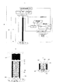
本発明に係る距離調整装置ないし方法、検査装置ないし方法の構成例と動作例について、図1乃至図5を用いて説明する。図1は、本発明の実施例1の検査装置100の構成を示す概略構成図である。図2は、本発明の実施例1である検査装置におけるセンサチップ120の構成図である。また、図3は、検査装置のうち、センサ部101と検査物102付近を拡大した部分の概略構成図である。
(Example 1: Adjusting the distance using a leakage electromagnetic field)
A configuration example and an operation example of the distance adjustment device or method and the inspection device or method according to the present invention will be described with reference to FIGS. FIG. 1 is a schematic configuration diagram illustrating a configuration of an
図4には、線幅2μmと10μmのマイクロストリップラインのセンサチップにおける、伝送線路と検査物間の距離とテラヘルツ波の伝播特性変化の解析例を示した。また、図5は、伝送線路と検査物間の距離を3種類の距離に設定した時に信号検出部108で計測したテラヘルツ波の伝播特性(パルス波形)と、各距離における検査物102と漏れ電磁界140との関係を模式的に説明した図である。
FIG. 4 shows an analysis example of the distance between the transmission line and the test object and the change in the propagation characteristics of the terahertz wave in the microstrip line sensor chip with line widths of 2 μm and 10 μm. 5 shows the propagation characteristics (pulse waveform) of the terahertz wave measured by the
まず、本実施例の検査装置100の構成について説明する。検査装置100は、センサ部101、検査物102を配置する為の検査物保持手段103、検査物102とセンサ部101間の距離を調整する為の距離調整手段110、漏れ電磁界強度調整手段114等を含む。距離調整手段110は、伝送線路と検査物間の距離を、伝送線路からの漏れ電磁界と検査物とが相互作用する距離に調整する為のものである。
First, the configuration of the
センサ部101の構成と動作について説明する。センサ部101には、テラヘルツ波の発生、伝送、検出を行う役割をもつセンサチップ120が実装されている。図2の様に、センサチップ120は、発生部132、伝送線路121、検出部133、GND(ground)層128、誘電体層125、貫通電極130等が基板129上に集積化された構成となっている。また、センサ部101はアーム115を介して、Z軸ステージ106に接続されている。Z軸ステージ106は、ステッピングモータによるμmオーダーの粗動と圧電アクチュエータによるnmオーダーの微動が行える精密ステージを使用しており、Z軸ステージ制御部107により制御される。
The configuration and operation of the sensor unit 101 will be described. A
センサチップ120について説明する。図2に示す様に、発生部132は、発生用信号線123、発生用半導体層126、発生用貫通電極130、GND層128、GND貫通電極134aから構成され、テラヘルツ波を発生する役割を果たす。発生部132は、発生用貫通電極130とGND貫通電極134aを介して、発生用電源112に電気的に接続されている。検出部133は、検出用信号線124、検出用半導体層127、検出用貫通電極131、GND層128、GND貫通電極134bから構成され、テラヘルツ波を検出する役割を果たす。検出部133は、検出用貫通電極131とGND貫通電極134bを介して、信号検出部108に電気的に接続されている。センサチップ120の裏面から、貫通電極を用いて、発生及び検出のための給電を行うことで、給電手段が介在して検査物102とセンサチップ120とが接触することを防止している。
The
本実施例の検査装置では、線幅2μmのマイクロストリップライン型の伝送線路121を用いている。発生部132で発生されたテラヘルツ波は、伝送線路121に結合され、上電極層122とGND層128に挟まれた誘電体中を伝搬する。そして、検出部133に結合され、電気信号として信号検出部108に取り出される。伝送線路121は、マイクロストリップラインに限られるものではなく、例えば、コプレナウェブガイド型の伝送線路等を用いてもよい。
In the inspection apparatus of this embodiment, a microstrip line
本実施例のセンサチップ120の構成材料について説明する。基板129の材料には、波長810nmの光パルスが透過する合成石英を使用した。発生用半導体層126及び検出用半導体層127は、膜厚2μmの低温成長ガリウムヒ素層であり、基板129上にAuの熱圧着法で転写されている。伝送線路121の上電極層122、発生用信号線123、検出用信号線124には、Ti/Au層(20nm/200nm)を用いた。GND層128には、Ti/Au/Ti層(20nm/500nm/20nm)を用いた。GND層128は熱圧着時の接合層としての役割も果たしている。誘電体層125は厚さ3μmであり、テラヘルツ帯において低損失の誘電体材料として実績のあるBCB(ベンゾシクロブテン)を用いた。また、発生用貫通電極130、GND貫通電極134a、検出用貫通電極131、GND貫通電極134bには、電気伝導性に優れ、埋め込み形成が容易なCuを用いた。なお、上記した構成材料は一例であり、これらに限られない。
The constituent materials of the
次に、本実施例のテラヘルツ波の発生及び検出について説明する。本検査装置では、テラヘルツ波の発生及び検出には、周知の光スイッチの方式を採用する。フェムト秒レーザ部113(チタンーサファイアレーザ、波長810nm)から、光学ゲート用の光パルス118を放射し、ビームスプリッタ(不図示)等により、発生用の光パルス118aと検出用の光パルス118bに分岐する。分岐した光パルスのうち発生用の光パルス118aは、センサ部101の発生部132に照射され、検出用の光パルス118bは、遅延光学系(不図示)を通過した後、センサ部101の検出部133に照射される。
Next, generation and detection of the terahertz wave according to the present embodiment will be described. In this inspection apparatus, a well-known optical switch system is adopted for generation and detection of terahertz waves. A femtosecond laser unit 113 (titanium-sapphire laser, wavelength 810 nm) emits a
発生用電源112により、発生用信号線123とGND層128に挟まれた発生用半導体層126の一部にバイアス電圧が印加されている。この状態で、GND層128に設けたスリット(不図示)を通じて、発生用半導体層126の電圧が印加された部分に光パルス118aが照射される。その結果、発生用半導体層126は光学的にゲートされ、光電流が励振されるのに伴いテラヘルツ波が発生する。発生したテラヘルツ波は、伝送線路121に結合する。
A bias voltage is applied to a part of the
伝送線路121中をテラヘルツ波が伝播する際、伝送線路121から微量の電磁界が漏れ出している。本明細書においては、こうした電磁界を漏れ電磁界140と呼ぶ。図3には、テラヘルツ波が紙面に垂直な方向に沿って伝播する際の、センサチップ120上のマイクロストリップラインに生じる電磁界が模式的に示されている。この漏れ電磁界140の強度は、主に、伝送線路の構成材料、形状、構造、テラヘルツ波信号の強度等により決まる。従って、周囲の状態や環境、雰囲気が略同じであれば、上記パラメータを決めることで、伝送線路からの漏れ電磁界の強度と、漏れ電磁界が影響を及ぼす領域が決まる。伝送線路121の近傍に検査物102がある場合、漏れ電磁界140と検査物102との間に相互作用が生じる。そのため、伝送線路121を伝播するテラヘルツ波の伝播特性が変化する。本発明の検査装置ないし方法は、この伝播特性の変化を利用して、検査物102の物性などの情報を取得する。
When the terahertz wave propagates through the
伝送線路121中を伝播したテラヘルツ波は検出部133に到達する。検出部133では、信号検出部108により、検出用信号線124とGND層128に挟まれた検出用半導体層127の一部にバイアス電圧が印加されている。そして、発生部と同様に、基板129裏面から、遅延光学系を通過してきた光パルス118bが照射される。光パルス118bにより、光学的にゲートされた検出用半導体層127に生じる光電流を信号検出部108でサンプリングすることで、テラヘルツ波の伝播特性が電気信号として検出される。
The terahertz wave that has propagated through the
なお、テラヘルツ波の発生及び検出方法は上記の方式に限られる訳ではない。例えば、発生部に、共鳴トンネルダイオードやガンダイオードなどの電磁波利得を有す半導体素子を用いてもよい。また、検出部にショットキーバリアダイオードなどの検波素子を用いる方式であってもよい。 The generation and detection method of the terahertz wave is not limited to the above method. For example, a semiconductor element having an electromagnetic wave gain such as a resonant tunneling diode or a Gunn diode may be used for the generating part. Further, a method using a detection element such as a Schottky barrier diode in the detection unit may be used.
センサ部101と検査物102周辺の構成について説明する。図3に示したように、検査物102は、検査物保持手段103により、センサ部101の伝送線路121と向き合うように、且つ伝送線路121と距離を離して配置されている。ここで、伝送線路121の表面と検査物102の表面との間の距離を『L』と定義する。本発明における装置ないし方法では、信号検出部108で検出するテラヘルツ波の検出信号の変化に応じて、距離調整手段110により、この距離Lが調整される。検査物102は、例えば、生体分子や薬品、高分子材料などであり、本実施例においては、リン酸緩衝溶液に溶解させたDNAを用いた。検査物102は、通常、乾いた状態で所定の厚みでもって配置される。
A configuration around the sensor unit 101 and the
また、検査物保持手段103は、例えば、テフロン(登録商標)やポリイミドなどの樹脂や、アルミなどの金属、或いは石英やサファイアなどの無機材料からなる平板である。本実施例では、比較的安価で成形加工が容易なポリエチレン樹脂を使用した。検査物102は、マイクロインジェクタなどの微小量滴下装置を使用して、検査物保持手段103上に数十ナノリットル程度滴下される。検査物保持手段103は、X-Yステージ104に機械的に固定されており、X-Yステージ制御部105によりX-Y面内で位置制御される。X-Yステージ104には、ステッピングモータによりμmオーダーの精度で動作可能な精密ステージを用いた。なお、検査効率(スループット)の向上のため、検査物102を、検査物保持手段103に複数個配置してもよい(図1参照)。この場合、各検査物102は、逐次、センサ部101の伝送線路121と向き合うように配置され、検査される。
The inspection object holding means 103 is a flat plate made of a resin such as Teflon (registered trademark) or polyimide, a metal such as aluminum, or an inorganic material such as quartz or sapphire. In this embodiment, a polyethylene resin that is relatively inexpensive and easy to mold is used. The
距離調整手段110及び漏れ電磁界強度調整手段114の構成について説明する。距離調整手段110は、信号検出部108、信号記録部109、演算処理部111、Z軸ステージ106、Z軸ステージ制御部107から構成され、これらは図1のように接続されている。また、演算処理部111は、比較部116と判断部117とを備えている。本実施例の検査装置100は、センサ部101上の伝送線路121表面と検査物102表面との間の距離Lを、センサ部101からの検出信号の変化に応じて調整可能な構成となっている。このような調整を実行する手段を本発明では距離調整手段110ないし距離変化手段と呼んでいる。
The configurations of the distance adjusting unit 110 and the leakage electromagnetic field intensity adjusting unit 114 will be described. The distance adjusting unit 110 includes a
また、演算処理部111から、漏れ電磁界強度調整手段114を介して、発生用電源112及びフェムト秒レーザ113に信号が送信される構成となっている。
In addition, a signal is transmitted from the arithmetic processing unit 111 to the generating
距離調整手段110は、以下のようなシステムにより、センサ部101からの検出信号の変化に応じて、センサチップ120と検査物102との間の距離を調整する。
The distance adjusting unit 110 adjusts the distance between the
センサ部101で検出されたテラヘルツ波は、信号検出部108においてサンプリングされて、検出信号はパルス波形として信号記録部109及び演算処理部111の比較部116に送信される。信号記録部109は、検出信号を保管すると共に、参照信号を比較部116に送信する役割を果たす。ここで、参照信号とは、典型的には、検査物102と漏れ電磁界140とが相互作用を生じていない状態における、信号検出部108で計測したテラヘルツ波の伝播特性(パルス波形)である(図5の[a]の状態参照)。
The terahertz wave detected by the sensor unit 101 is sampled by the
検査物102と漏れ電磁界140とが、既に相互作用を生じている場合には、参照信号は、距離Lを変化させる前の状態において検出したパルス波形であってもよい。この場合でも、検査物102とセンサチップ120を目標の距離まで精度良く調整することができる。
When the
比較部116においては、信号記録部109に保管された参照信号のパルス波形と、信号検出部108から送信された検出信号のパルス波形とが比較される。判断部117は、比較波形の有意差の有無を判断し、判断結果に応じて、Z軸ステージ制御部107に信号を送信しZ軸ステージ106をZ軸方向に動かす。尚、ここではセンサ部側を移動させるが、検査物保持手段側をZ軸方向に動かしてもよい。要は、センサ部101と検査物102が相対的にZ軸方向に動かされて、センサ部101上の伝送線路121表面と検査物102表面との間の距離が変化すればよい。
The
次に、距離調整手段110及び漏れ電磁界調整手段114を備えた本実施例の検査装置の検査方法について説明する。 Next, an inspection method of the inspection apparatus according to this embodiment provided with the distance adjustment unit 110 and the leakage electromagnetic field adjustment unit 114 will be described.
図5の[a]の状態のように、伝送線路と検査物とが十分に離れている場合、すなわち、伝送線路121からの漏れ電磁界140と検査物102との相互作用が生じていない距離Lでは、伝送線路121に特有のパルス波形[a]が得られる。これは、本実施例における参照信号であり、センサチップ120の構成とテラヘルツ波の強度によって決まる。参照信号は、図4の解析結果においては、距離Lが50μmの時のパルス波形に対応する。
As in the state of [a] in FIG. 5, when the transmission line is sufficiently separated from the inspection object, that is, the distance at which the interaction between the leakage
このように、センサ部101と検査物102とが十分に離れた場合には、信号検出部108からのパルス波形が参照信号と同じであるので、判断部117より変化無の信号がZ軸ステージ制御部107に送信される。信号を受けたZ軸ステージ制御部は、Z軸ステージを粗動のステップ(例えば、1mm乃至1μmのレンジのステップ)で動かし、再び、センサ部101においてテラヘルツ波の伝播特性の測定を行う。
As described above, when the sensor unit 101 and the
テラヘルツ波の伝播特性を測定しながらZ軸ステージ106を動かし、センサチップ120を検査物102に近づけていくと、やがて、参照信号に比べて、微量に減衰や遅延が生じたパルス波形[b]が得られる距離に到達する。図5の[b]の状態に示したように、この距離は、漏れ電磁界140と検査物102の表面とが相互作用を開始する距離(距離L0)である。距離L0は、伝送線路の構成材料、形状、構造、テラヘルツ波信号の強度等により決まり、相互作用の開始の検知で距離L0を検出することで、検査装置100のZ軸ステージ制御部107は、検査物102表面とセンサチップ120との相対的な距離を認識する。すなわち、解析結果から、本実施例のセンサチップにおいては、伝送線路と検査物間の距離Lを凡そ10μmに近接させることで、電界強度の変化及び位相遅延が生じることが分かっている。よって、Z軸ステージ制御部107は、検査物102表面とセンサチップ120との相対的な距離を認識することができる。図4は、電界強度(peak electric field intensity)の変化及び位相遅延(peak
position)が凡そ10μmの距離で顕著に現れ始めることを示している。
When the Z-
position) starts to appear prominently at a distance of approximately 10 μm.
この時、演算処理部111は、検出信号と参照信号のパルス波形に有意差があると判断し、Z軸ステージ制御部107に信号を送る。こうして、これの制御モードを、Z軸ステージ106を微動(例えば、1μm乃至10nmのレンジのステップ)で動作させるモードに切替える。
At this time, the arithmetic processing unit 111 determines that there is a significant difference between the pulse waveforms of the detection signal and the reference signal, and sends a signal to the Z-axis stage control unit 107. Thus, the control mode is switched to a mode in which the Z-
更に、テラヘルツ波の伝播特性を測定しつつ、Z軸ステージ106を動作して、センサチップ120と検査物102を距離Lmまで接近させる(例えばL=Lm=1μm、図5の[c]の状態参照)。この距離は、Z軸ステージ制御部107が距離L0を認識した後に、分かっている量ずつZ軸ステージ106を微動モードで移動して達成したものである。
Further, while measuring the propagation characteristics of the terahertz wave, the Z-
このとき、検査物102と漏れ電磁界140との間には十分に強い相互作用が生じる。言い換えると、伝送線路121を伝播するテラヘルツ波と検査物102とが強く相互作用を生じる状態となる。従って、伝送線路121を伝播するテラヘルツ波の伝播特性は変化するため、参照信号と比較して強い減衰と遅延が生じたパルス波形[c]が得られる。解析結果から、本実施例のセンサチップにおいては、距離Lを10μm以下に近接させた領域では、距離Lの変化に対して電界強度及び位相遅延は、ほぼ指数関数的に変化する。また、本実施例の距離条件(L=Lm=1μm)であれば、伝送線路と検査物の状態を非接触に保ちながら測定を行なうことも可能である。
At this time, a sufficiently strong interaction occurs between the
上記の検査方法は、テラヘルツ波発生部と伝送線路と検出部とを含むセンサを用意するステップと、検査物配置ステップと、粗動ステップと、距離認識ステップと、距離設定ステップと、データ取得ステップと、を含むものである。ここにおいて、検査物配置ステップでは、センサ120の伝送線路121と対向する位置に、伝送線路と離間して検査物102を配置する。粗動ステップでは、テラヘルツ波発生部132から発せられ伝送線路121を伝播してきたテラヘルツ波を検出する検出部133の検出信号をモニタしながら、伝送線路と検査物間の距離を近付ける。距離認識ステップでは、検出部133の検出信号の変化から、伝送線路121からの漏れ電磁界140と検査物102の表面とが相互作用を開始する距離L0を認識する。距離設定ステップでは、前記距離認識の後に、伝送線路121と検査物102間の距離を、漏れ電磁界と検査物とが相互作用する目標の距離に設定する。データ取得ステップでは、前記目標の距離に設定した状態において、伝送線路121を伝播するテラヘルツ波と検査物102との相互作用の状態を反映する検出部133の検出信号に基づき、検査物の情報を取得する。
The inspection method includes a step of preparing a sensor including a terahertz wave generation unit, a transmission line, and a detection unit, an inspection object placement step, a coarse movement step, a distance recognition step, a distance setting step, and a data acquisition step. And. Here, in the inspection object arranging step, the
次の様な動作を付加してもよい。すなわち、上記距離認識ステップと上記データ取得ステップの間で、演算処理部111から漏れ電磁界強度調整手段114に信号が送られ、発生用電源112により発生用半導体層126に印加されるバイアス電圧を5Vから20Vに変更してもよい。また、漏れ電磁界強度調整手段114からフェムト秒レーザ113に信号が送られ、発生用半導体層126を光ゲートする為の光パルス118の光出力が1mWから10mWに変更されてもよい。この時、発生部132から発生するテラヘルツ波の信号強度が増加する為、伝送線路121からの漏れ電磁界の強度が、更に増加する。この結果、検査物102と漏れ電磁界140との相互作用の強度と領域が実効的に増加する。そして、この状態において、テラヘルツ波の伝播特性を信号検出部108にて検出し、検査物の物性情報の取得を行う。この漏れ電磁界増加ステップは、例えば、上記距離認識ステップの後に、或いは上記距離設定ステップの後に実行することができる。
The following operation may be added. That is, between the distance recognition step and the data acquisition step, a signal is sent from the arithmetic processing unit 111 to the leakage electromagnetic field strength adjusting means 114, and the bias voltage applied to the
本実施例の装置ないし方法によれば、距離調整手段110により、センサ部101の伝送線路121を伝搬するテラヘルツ波の伝播特性をモニタし、検出信号と参照信号を比較しながら、センサ部100と検査物102を近づける。そして、伝送線路121表面から微弱に漏れ出した漏れ電磁界140と検査物102表面とが相互作用を開始する距離(L0)を認識する。すなわち、センサチップ120と検査物102間の相対的な距離を、テラヘルツ波の伝播特性の変化から認識することができる。また、距離調整手段110を用いて、距離L0から、検査物102とセンサチップ120を近接させて、漏れ電磁界140と検査物102間で十分な相互作用を生じる好適な距離にまで調整することが可能である。このように伝送線路と検査物間の距離を調整することで伝送線路と検査物間の状態を一義的に決めることが可能となるため、感度や再現性の良い計測が実現される。
According to the apparatus or method of the present embodiment, the distance adjustment unit 110 monitors the propagation characteristics of the terahertz wave propagating through the
また、本検査装置は、漏れ電磁界強度調整手段114を備え、伝送線路と検査物間の距離を、相互作用が生じる距離まで近接させた状態で、伝送線路からの漏れ電磁界の強度を増加させることも可能である。この状態で、伝送線路からの漏れ電磁界と検査物との相互作用の状態を、テラヘルツ波の伝播特性として取得することで、より感度良く検査物の物性データなどの情報を取得できる。 In addition, this inspection apparatus includes a leakage electromagnetic field strength adjusting means 114, and increases the strength of the leakage electromagnetic field from the transmission line while keeping the distance between the transmission line and the inspection object close to the distance at which the interaction occurs. It is also possible to make it. In this state, by acquiring the state of interaction between the leakage electromagnetic field from the transmission line and the test object as the propagation characteristic of the terahertz wave, information such as physical property data of the test object can be acquired with higher sensitivity.
このように、本実施例の装置ないし方法によれば、伝送線路と検査物間の距離を調整することで伝送線路と検査物間の状態を一義的に決めることが可能となるため、測定感度や再現性の良い検査が実現される。また、オンチップ計測に比べて、高速かつ低コストで漏れ電磁界を用いた計測を行なうことが可能となる。更に、漏れ電磁界を用いたテラヘルツ波計測を、顕微鏡などのその場観察手段として応用することが可能となる。また、伝送線路と検査物を非接触の状態でも測定可能となるので、センサの劣化や洗浄及び交換の頻度が低減され、より経済的な検査が可能となる。 Thus, according to the apparatus or method of the present embodiment, the state between the transmission line and the inspection object can be uniquely determined by adjusting the distance between the transmission line and the inspection object. Inspection with good reproducibility is realized. In addition, it is possible to perform measurement using a leakage electromagnetic field at high speed and low cost compared to on-chip measurement. Furthermore, terahertz wave measurement using a leakage electromagnetic field can be applied as an in-situ observation means such as a microscope. In addition, since the transmission line and the inspection object can be measured in a non-contact state, the frequency of sensor deterioration, cleaning and replacement is reduced, and more economical inspection is possible.
ここで、従来のオンチップ計測では、漏れ電磁界との相互作用を計測する方式を、顕微鏡等のその場観察やin−situ計測に用いることは難しい。なお、従来のオンチップ計測とは、例えば、非特許文献1(APL,88,212511、2006)に開示された計測のことである。測定感度や再現性の観点から、観察対象物と伝送線路の状態を一義的に決めることが重要となる。非特許文献1には、前記距離を調整する本発明の概念について、開示も示唆もされていない。 Here, in the conventional on-chip measurement, it is difficult to use the method of measuring the interaction with the leakage electromagnetic field for in-situ observation such as a microscope or in-situ measurement. The conventional on-chip measurement is, for example, the measurement disclosed in Non-Patent Document 1 (APL, 88, 212511, 2006). From the viewpoint of measurement sensitivity and reproducibility, it is important to uniquely determine the state of the observation object and the transmission line. Non-Patent Document 1 does not disclose or suggest the concept of the present invention for adjusting the distance.
なお、本発明は、前述したように、漏れ電磁界を利用して前記距離の調整を行うものである。本発明は、テラヘルツ波が発生されてから、該テラヘルツ波が検査物で反射して検出されるまでの伝搬時間を求めることによって、前記距離を導出するものとは異なる。 In the present invention, as described above, the distance is adjusted using a leakage electromagnetic field. The present invention is different from that in which the distance is derived by obtaining the propagation time from when the terahertz wave is generated until the terahertz wave is reflected and detected by the inspection object.
(実施例2:検査用及び距離調整用の伝送線路)
図6は、本発明の実施例2である距離調整装置ないし方法、検査装置ないし方法の構成を示す概略構成図である。図7は、本実施例の距離調整装置ないし方法、検査装置ないし方法に用いたセンサチップの構成図である。
(Example 2: Transmission line for inspection and distance adjustment)
FIG. 6 is a schematic configuration diagram showing a configuration of a distance adjustment device or method and an inspection device or method that are
本実施例の検査装置200も、センサ部101、検査物102を配置する為の検査物保持手段103、検査物102とセンサ部101間の距離を調整する距離調整手段110、漏れ電磁界強度調整手段114等から構成される。本実施例においては、実施例1と異なり、漏れ電磁界強度調整手段114は、X-Yステージ104をX-Y面内で移動・制御するX-Yステージ制御部105に接続されている。
The
本実施例では、図7の様に、センサチップ220は、発生部132、検査用伝送線路221、距離調整用伝送線路222、検出部133、GND層128、誘電体層125、貫通電極130等が基板129上に集積化された構成となっている。テラヘルツ波の発生及び検出には、実施例1と同様に、光スイッチの方式を採用している。また、検査用伝送線路221及び距離調整用伝送線路222には、実施例1と同様に、マイクロストリップライン型の伝送線路を用いている。
In this embodiment, as shown in FIG. 7, the
検査用伝送線路221は、長さが300μm、線幅が2μmのマイクロストリップラインであり、検査物102の検査に用いる。一方、距離調整用伝送線路222は、長さが300μm、線幅が10μmのマイクロストリップラインであり、検査物102とセンサチップ220の距離を調整するために用いる。検査用伝送線路221と距離調整用伝送線路222は、50μm離した位置に並列的に配置されている。
The
一般的に、伝送線路からの漏れ電磁界の強度は、伝送線路の構成材料、形状、構造、テラヘルツ波信号の強度等により決まる。マイクロストリップラインにおいては、他の構造が同じである場合、線幅の細い線路ほど漏れ電磁界の強度や漏れ出す領域が増加する。つまり、検査物と伝送線路の間の距離Lが同じであるとき、線幅の細い線路を伝播するテラヘルツ波は、検査物とより強く相互作用を生じることになる。 In general, the strength of the leakage electromagnetic field from the transmission line is determined by the constituent material, shape, structure, and strength of the terahertz wave signal of the transmission line. In the microstrip line, when the other structures are the same, the line with a narrower line width increases the strength of the leakage electromagnetic field and the leaked area. That is, when the distance L between the inspection object and the transmission line is the same, the terahertz wave propagating through the line having a narrow line width has a stronger interaction with the inspection object.
本実施例の検査装置においては、はじめに、距離調整用伝送線路222からの漏れ電磁界と検査物102との相互作用を用いて、距離調整用伝送線路222と検査物102との距離を調整する。実施例1と同様、距離調整手段110により、距離Lは、距離調整用伝送線路222を伝播するテラヘルツ波と検査物102とが相互作用を生じる距離にまで調整される。具体的な方法は、実施例1と同様であるため、説明は割愛する。
In the inspection apparatus of the present embodiment, first, the distance between the distance
ここで、距離調整手段110から漏れ電磁界強度調整手段114を介してX-Yステージ制御部105に信号が送られ、X-Yステージ104が水平方向に50μm移動させられ、検査部位が検査用伝送線路221の下に配置される。線幅の細い検査用伝送線路221においては、同じ距離Lでも、伝播するテラヘルツ波と検査物102との相互作用の強度と領域が実効的に増加する。この状態において、テラヘルツ波の伝播特性を信号検出部108にて検出し、検査物102の物性などの情報の取得を行う。検査用伝送線路221と距離調整用伝送線路222の間で、同じ距離Lにおいて電界強度の変化及び位相遅延がどの程度異なるかは、図4に示されている。
Here, a signal is sent from the distance adjusting unit 110 to the XY stage control unit 105 via the leakage electromagnetic field intensity adjusting unit 114, the
漏れ電磁界増加ステップとして、実施例1で述べた方法と本実施例で述べた方法の両方を行うこともできる。また、上記例では2種類の伝送線路を設けたが、漏れ電磁界の異なる3種類以上の伝送線路を設けてもよい。この場合、少なくとも1つが距離調整用伝送線路であって、少なくとも1つが検査用伝送線路である。 As the leakage electromagnetic field increasing step, both the method described in the first embodiment and the method described in the present embodiment can be performed. In the above example, two types of transmission lines are provided, but three or more types of transmission lines having different leakage electromagnetic fields may be provided. In this case, at least one is a distance adjustment transmission line and at least one is an inspection transmission line.
このように、漏れ電磁界強度の異なる2種類以上の伝送線路を配置し、弱い第1の漏れ電磁界の伝送線路で距離Lを調整して、第1の漏れ電磁界強度より強い第2の漏れ電磁界強度の伝送線路でテラヘルツ波の伝播特性を測定する。このことで、より高感度の測定が期待される。 In this way, two or more types of transmission lines having different leakage electromagnetic field strengths are arranged, and the distance L is adjusted by the transmission line of the weak first leakage electromagnetic field, so that the second stronger than the first leakage electromagnetic field strength. Measure the propagation characteristics of terahertz waves on transmission lines with leakage electromagnetic field strength. As a result, more sensitive measurement is expected.
また、実施例1と同様に、伝送線路と検査物間の距離を調整することで伝送線路と検査物間の状態を一義的に決めることが可能となるため、測定感度や再現性の良い検査が実現される。また、オンチップ計測に比べて、高速かつ低コストで、漏れ電磁界を用いた計測を行なうことが可能となる。更に、漏れ電磁界を用いたテラヘルツ波計測を、顕微鏡などのその場観察手段として応用することが可能となる。また、伝送線路と検査物が非接触の状態でも測定可能となるので、センサの劣化や洗浄及び交換の頻度が低減され、より経済的な検査が可能となる。 Also, as in Example 1, it is possible to uniquely determine the state between the transmission line and the inspection object by adjusting the distance between the transmission line and the inspection object, so that inspection with good measurement sensitivity and reproducibility is possible. Is realized. In addition, it is possible to perform measurement using a leakage electromagnetic field at high speed and low cost compared to on-chip measurement. Furthermore, terahertz wave measurement using a leakage electromagnetic field can be applied as an in-situ observation means such as a microscope. In addition, since measurement is possible even when the transmission line and the inspection object are not in contact with each other, the frequency of sensor deterioration, cleaning, and replacement is reduced, and more economical inspection is possible.
(実施例3:内視鏡)
図8は、本発明の第3の実施例である本発明の検査装置ないし方法を用いた内視鏡システムを示す概略構成図である。ここで、図8(a)は本システムの構成図、図8(b)は領域Aの拡大断面図、図8(c)は測定時におけるセンサ部の状態の一例である。なお、図8において実施例1と同様の構成要素には同一の符号を付し、詳細な説明は省略する。
(Example 3: Endoscope)
FIG. 8 is a schematic configuration diagram showing an endoscope system using the inspection apparatus or method of the present invention which is the third embodiment of the present invention. Here, FIG. 8A is a configuration diagram of the present system, FIG. 8B is an enlarged cross-sectional view of the region A, and FIG. 8C is an example of the state of the sensor unit during measurement. In FIG. 8, the same components as those in the first embodiment are denoted by the same reference numerals, and detailed description thereof is omitted.
本実施例の内視鏡システム300の構成について説明する。内視鏡システム300は、内視鏡プローブ320、検査物302とセンサ部301間の距離を調整する距離調整手段310、及び先の実施例で説明した各構成要素等から構成される。内視鏡プローブ320は、センサ部301、可撓管321、Z軸粗動部328、Z軸微動部329などから構成される。
A configuration of the
可撓管321には、主に発生用光ファイバ324、検出用光ファイバ325、信号線323、Z軸粗動部328などが内封されており、先端には圧電アクチュエータによるnmオーダーの微動が行えるZ軸微動部329が配置されている。ここでは、Z軸粗動部328には、μmオーダーの粗動が行なえる回転式のマイクロステージを用いた。回転式のマイクロステージでは、可撓管321内に回転可能に内挿され微細なめねじ内面を持つ円筒部材を回転して、センサチップ120が固定され微細なおねじ外面を持つ円板部材を可撓管321の軸方向に移動することで、センサ部301を動かす。図8(b)は、センサ部301のセンサチップ120が固定された円板部材が内方に退避した状態を示し、図8(c)は、この円板部材が外方に出た状態を示す。
The
センサ部301は、内視鏡320の先端に配置されたセンサチップ120(実施例1で説明済)から構成される。センサチップ120は、発生用光ファイバ324及び検出用光ファイバ325を介してフェムト秒レーザ部113と接続され、信号線323を介して発生用電源112及び信号検出部108と接続されている。また、センサチップ120の表面には保護膜330となるSOG(スピンオングラス)膜が約50nmコートされており、センサ部の劣化や損傷を防止している。本実施例においても、実施例1と同様に、テラヘルツ波の発生及び検出には光スイッチの方式を採用し、検査用伝送線路121にはマイクロストリップライン型の伝送線路を用いている。
The
本実施例の内視鏡システムは以下のように動作する。本実施例においては、体内に内視鏡プローブ320を挿入し体内器官の内壁面の検査を行なう場合を例に説明する。また、センサチップ120の動作は実施例1にて説明した通りである。
The endoscope system of the present embodiment operates as follows. In the present embodiment, a case where the
まず、第1の粗動ステップとなる内視鏡プローブ320の挿入により、検査物302となる内壁面と内視鏡プローブ320の先端が接触する。この際、内視鏡先端に位置する圧電アクチュエータからなるZ軸微動部329により内視鏡先端と検査物302の接触が検知される。
First, the insertion of the
次に、第2の粗動ステップとして、センサ部301におけるテラヘルツ波の伝播特性の測定を行いながらZ軸粗動部328を動作させ、センサチップ120を検査物102に近付ける。テラヘルツ波の伝播特性に変化が生じる相互作用の開始する距離L0を検知したら、微動ステップに切替え、Z軸微動部329を動作させて目標の距離までセンサチップ120を検査物102に接近させる(図8(c)参照)。漏れ電磁界140と検査物間で十分な相互作用を生じる好適な距離にまで調整した状態で、伝送線路121を伝播するテラヘルツ波と検査物との相互作用の状態を反映する検出部133の検出信号に基づき、体内器官内壁の物性情報を取得する。
Next, as a second coarse movement step, the Z-axis
このように、テラヘルツ波の漏れ電磁界を用いた計測を内視鏡に用いた場合でも、本発明の特徴である距離調整手段ないし距離変化手段を有することで、十分な相互作用が生じる好適な距離の条件での測定が可能となる。こうして、高感度でかつ再現性の良い内視鏡検査が実現される。本実施例では体内器官の検査についてのみ説明したが、本実施例の内視鏡システムは、例えば、微細な配管や隙間などを検査するための産業用内視鏡としても当然用いることができる。 As described above, even when the measurement using the leakage electromagnetic field of the terahertz wave is used for the endoscope, the distance adjustment unit or the distance change unit, which is a feature of the present invention, is suitable for causing sufficient interaction. Measurement under distance conditions is possible. Thus, endoscopic examination with high sensitivity and good reproducibility is realized. Although only the inspection of the internal organs has been described in the present embodiment, the endoscope system of the present embodiment can naturally be used as, for example, an industrial endoscope for inspecting fine pipes and gaps.
101、904、 センサ部(センサ)
102、302、907 検査物
103、908 検査物保持部(検査物保持手段)
104 移動部(X-Yステージ)
108、111、906 処理部(信号検出部、演算処理部)
109 記憶部(信号記録部)
110、310、909 距離調整手段(距離変化手段)
121、221、222、902 伝送線路
132、901 テラヘルツ波発生部
133、903 センサ部の検出部
905、1005 遅延部
108、111、906 処理部(信号検出部、演算処理部)
101, 904, sensor part (sensor)
102, 302, 907 Inspection object
103,908 Inspection object holding part (Inspection object holding means)
104 Moving part (XY stage)
108, 111, 906 Processor (signal detector, arithmetic processor)
109 Storage unit (signal recording unit)
110, 310, 909 Distance adjustment means (distance changing means)
121, 221, 222, 902 Transmission line
132,901 terahertz wave generator
133, 903 Sensor detector
905, 1005 delay section
108, 111, 906 Processor (signal detector, arithmetic processor)
Claims (12)
前記伝送線路を伝搬するテラヘルツ波を発生させるための発生部と、
前記伝送線路を伝搬したテラヘルツ波を検出するための検出部と、
前記伝送線路におけるテラヘルツ波の伝搬方向に対して交差する方向に前記距離を変更させるための距離変更手段と、
前記距離変更手段を制御するための制御部と、を備え、
前記伝送線路を伝搬するテラヘルツ波と前記検査物とが相互作用するように構成されており、
前記制御部は、前記検出部で検出したテラヘルツ波のうち、少なくとも該相互作用したテラヘルツ波に関する情報を用いて前記距離変更手段を制御することを特徴とする距離調整装置。 A distance adjustment device for adjusting a distance between the transmission line and an inspection object using the terahertz wave , including a transmission line for propagating the terahertz wave ,
A generator for generating a terahertz wave propagating through the transmission line ;
A detection unit for detecting a terahertz wave propagated through the transmission line,
A distance change means for varying exposed the distance in a direction intersecting the propagation direction of the terahertz wave in the transmission line,
A control unit for controlling the distance changing means ,
The terahertz wave propagating through the transmission line is configured to interact with the inspection object,
Wherein the control unit, the out of the terahertz wave detected by the detection unit, a distance adjusting device and controls the distance changing means using information on the terahertz waves at least said interaction.
前記検出部で検出したテラヘルツ波に関する情報が、前記参照情報から変化したとき、前記相互作用が生じたことを判断するための判断部と、を備えることを特徴とする請求項1あるいは2に記載の距離調整装置。 Said interaction Keru Contact the absence Ji raw said distance, a storage unit for storing information about the terahertz wave detected by the detecting unit as the reference information,
Information about the terahertz wave detected by the detection unit, when the change from the reference information, according to claim 1 or 2, characterized in that and a determination unit for determining that the interaction occurs Distance adjustment device.
前記判断部の結果を用いて、前記漏れ電磁界の強度を調整するための調整手段を備えることを特徴とする請求項3に記載の距離調整装置。The distance adjusting device according to claim 3, further comprising an adjusting unit configured to adjust the strength of the leakage electromagnetic field using a result of the determination unit.
前記検出部で検出したテラヘルツ波の信号であり、前記遅延部を用いて得る、前記タイミングの異なる複数の信号から、該テラヘルツ波の時間波形に関する情報を取得するための処理部と、を備えることを特徴とする請求項1乃至4のいずれか1項に記載の距離調整装置。 A delay unit for changing the timing of detecting the terahertz wave in the detection unit;
Wherein a terahertz wave signal detected by the detection unit, obtained using the delay unit, different from the plurality of signals said timing, be provided with a processing unit for obtaining information about the time waveform of the terahertz wave The distance adjusting device according to claim 1, wherein:
前記検査物を保持するための検査物保持部を備え、
前記テラヘルツ波に関する情報を用いて前記距離を決定し、該決定された距離で前記相互作用させ、該相互作用したテラヘルツ波に関する情報を用いて前記検査物を検査することを特徴とする検査装置。 An inspection device for inspecting the inspection object, comprising the distance adjusting device according to any one of claims 1 to 6 ,
An inspection object holding unit for holding the inspection object;
An inspection apparatus , wherein the distance is determined using information on the terahertz wave, the interaction is performed at the determined distance, and the inspection object is inspected using information on the interacted terahertz wave .
前記伝送線路を先端に設ける内視鏡プローブを備えることを特徴とする検査装置。 An inspection device for inspecting the inspection object, comprising the distance adjusting device according to any one of claims 1 to 6 ,
An inspection apparatus comprising an endoscope probe having the transmission line at a tip .
前記伝送線路と前記検査物との間の第1の距離において、前記伝送線路を伝搬したテラヘルツ波を検出する第1の検出工程と、A first detection step of detecting a terahertz wave propagated through the transmission line at a first distance between the transmission line and the inspection object;
前記伝送線路におけるテラヘルツ波の伝搬方向に対して交差する方向に関して、前記第1の距離を第2の距離に変更する変更工程と、Regarding the direction intersecting the propagation direction of the terahertz wave in the transmission line, a changing step of changing the first distance to a second distance;
前記第2の距離において、前記伝送線路を伝搬したテラヘルツ波を検出する第2の検出工程と、 A second detection step of detecting a terahertz wave propagated through the transmission line at the second distance;
前記第1及び第2の検出工程で検出したテラヘルツ波を用いて、前記伝送線路と前記検査物の距離を認識する認識工程と、を含み、Recognizing the distance between the transmission line and the inspection object using the terahertz waves detected in the first and second detection steps,
前記認識の後に決定された距離において、前記伝送線路を伝搬するテラヘルツ波と前記検査物とを相互作用させ、該相互作用したテラヘルツ波を用いて前記検査物を検査することを特徴とする検査方法。An inspection method characterized by causing a terahertz wave propagating through the transmission line to interact with the inspection object at a distance determined after the recognition, and inspecting the inspection object using the interacted terahertz wave .
前記第3の距離において、前記伝送線路を伝播するテラヘルツ波による漏れ電磁界と前記検査物との相互作用に関する情報を取得して前記検査物を検査することを特徴とする請求項9に記載の検査方法。10. The inspection object according to claim 9, wherein at the third distance, the inspection object is inspected by acquiring information on an interaction between a leakage electromagnetic field caused by a terahertz wave propagating through the transmission line and the inspection object. Inspection method.
前記テラヘルツ波を伝搬させるための伝送線路を、漏れ電磁界の強度の弱い第1の伝送線路から、第1の伝送線路より漏れ電磁界の強度が強い第2の伝送線路に切替えることで前記漏れ電磁界の強度を増加させるか、あるいは、
前記伝送線路を伝播するテラヘルツ波の強度を増加することで前記漏れ電磁界の強度を増加させることを特徴とする請求項11に記載の検査方法。
In the increasing step,
By switching the transmission line for propagating the terahertz wave from the first transmission line having a weak leakage electromagnetic field strength to the second transmission line having a stronger leakage electromagnetic field strength than the first transmission line, the leakage is caused. Increase the strength of the electromagnetic field, or
The inspection method according to claim 11, wherein the intensity of the leakage electromagnetic field is increased by increasing the intensity of the terahertz wave propagating through the transmission line.
Priority Applications (2)
| Application Number | Priority Date | Filing Date | Title |
|---|---|---|---|
| JP2008165175A JP4859250B2 (en) | 2007-08-31 | 2008-06-25 | Distance adjustment apparatus and method for inspection object, inspection apparatus and method |
| US12/201,745 US7737402B2 (en) | 2007-08-31 | 2008-08-29 | Distance adjusting apparatus and method, and object examining apparatus and method |
Applications Claiming Priority (3)
| Application Number | Priority Date | Filing Date | Title |
|---|---|---|---|
| JP2007224942 | 2007-08-31 | ||
| JP2007224942 | 2007-08-31 | ||
| JP2008165175A JP4859250B2 (en) | 2007-08-31 | 2008-06-25 | Distance adjustment apparatus and method for inspection object, inspection apparatus and method |
Publications (3)
| Publication Number | Publication Date |
|---|---|
| JP2009075071A JP2009075071A (en) | 2009-04-09 |
| JP2009075071A5 JP2009075071A5 (en) | 2010-03-11 |
| JP4859250B2 true JP4859250B2 (en) | 2012-01-25 |
Family
ID=40610163
Family Applications (1)
| Application Number | Title | Priority Date | Filing Date |
|---|---|---|---|
| JP2008165175A Expired - Fee Related JP4859250B2 (en) | 2007-08-31 | 2008-06-25 | Distance adjustment apparatus and method for inspection object, inspection apparatus and method |
Country Status (1)
| Country | Link |
|---|---|
| JP (1) | JP4859250B2 (en) |
Families Citing this family (3)
| Publication number | Priority date | Publication date | Assignee | Title |
|---|---|---|---|---|
| US9194829B2 (en) | 2012-12-28 | 2015-11-24 | Fei Company | Process for performing automated mineralogy |
| DE102018109250A1 (en) * | 2018-04-18 | 2019-10-24 | INOEX GmbH Innovationen und Ausrüstungen für die Extrusionstechnik | Method and THz measuring device for measuring a measurement object with electromagnetic radiation |
| CN115951221B (en) * | 2022-01-04 | 2023-07-25 | 国仪量子(合肥)技术有限公司 | Method and equipment for detecting leakage discharge performance of battery pack |
Family Cites Families (4)
| Publication number | Priority date | Publication date | Assignee | Title |
|---|---|---|---|---|
| JP3950820B2 (en) * | 2003-06-25 | 2007-08-01 | キヤノン株式会社 | High frequency electric signal control device and sensing system |
| JP2006218193A (en) * | 2005-02-14 | 2006-08-24 | Pentax Corp | Optical element |
| JP4636917B2 (en) * | 2005-03-28 | 2011-02-23 | キヤノン株式会社 | Sample holding device, sample detection apparatus and sample detection method using the same |
| JP2006275910A (en) * | 2005-03-30 | 2006-10-12 | Canon Inc | System and method for position sensing |
-
2008
- 2008-06-25 JP JP2008165175A patent/JP4859250B2/en not_active Expired - Fee Related
Also Published As
| Publication number | Publication date |
|---|---|
| JP2009075071A (en) | 2009-04-09 |
Similar Documents
| Publication | Publication Date | Title |
|---|---|---|
| JP4829669B2 (en) | Sample information acquisition apparatus and sample information acquisition method | |
| JP4546326B2 (en) | Sensing device | |
| JP4878180B2 (en) | Inspection equipment using electromagnetic waves | |
| JP4402026B2 (en) | Sensing device | |
| JP5037929B2 (en) | Information acquisition apparatus and method for an object using terahertz waves | |
| JP5173850B2 (en) | Inspection device | |
| US7737402B2 (en) | Distance adjusting apparatus and method, and object examining apparatus and method | |
| EP2217910A2 (en) | Inspection apparatus and inspection method using electromagnetic wave | |
| JP2015083964A (en) | Information acquisition device and information acquisition method for acquiring information of analyte by using terahertz wave | |
| JP2015049096A (en) | Polarization sensitivity terahertz wave detector | |
| KR100822680B1 (en) | A laser ultrasonic apparatus and method to detect micro multi-cracks | |
| JP4859250B2 (en) | Distance adjustment apparatus and method for inspection object, inspection apparatus and method | |
| JP2010281700A (en) | Apparatus and method for acquiring time waveform of terahertz wave | |
| US8981300B2 (en) | Electromagnetic wave pulse measuring device and method, and application device using the same | |
| US11644442B2 (en) | System and method for nanoscale photoacoustic tomography | |
| US7795588B2 (en) | Inspection apparatus | |
| JP2011085412A (en) | Terahertz focusing method, terahertz focusing device, and terahertz focusing program | |
| JP5301770B2 (en) | Thin film semiconductor crystallinity measuring apparatus and method | |
| JP5583934B2 (en) | Evaluation method of chemical degradation of concrete | |
| US20150241348A1 (en) | Information acquiring apparatus and information acquiring method | |
| CN109164046B (en) | Picosecond ultrasonic cell imaging device and method | |
| Koshikawa et al. | Application to thermal analysis using optical probe technique | |
| JP3853248B2 (en) | Electrical characteristic evaluation apparatus and method | |
| KR20240005356A (en) | Device and method for estimating residual stress | |
| CN100562743C (en) | Sensor device |
Legal Events
| Date | Code | Title | Description |
|---|---|---|---|
| A521 | Written amendment |
Free format text: JAPANESE INTERMEDIATE CODE: A523 Effective date: 20100119 |
|
| A621 | Written request for application examination |
Free format text: JAPANESE INTERMEDIATE CODE: A621 Effective date: 20100119 |
|
| A977 | Report on retrieval |
Free format text: JAPANESE INTERMEDIATE CODE: A971007 Effective date: 20110928 |
|
| TRDD | Decision of grant or rejection written | ||
| A01 | Written decision to grant a patent or to grant a registration (utility model) |
Free format text: JAPANESE INTERMEDIATE CODE: A01 Effective date: 20111004 |
|
| A01 | Written decision to grant a patent or to grant a registration (utility model) |
Free format text: JAPANESE INTERMEDIATE CODE: A01 |
|
| A61 | First payment of annual fees (during grant procedure) |
Free format text: JAPANESE INTERMEDIATE CODE: A61 Effective date: 20111031 |
|
| FPAY | Renewal fee payment (event date is renewal date of database) |
Free format text: PAYMENT UNTIL: 20141111 Year of fee payment: 3 |
|
| LAPS | Cancellation because of no payment of annual fees |