JP4851288B2 - Ultrasonic diagnostic equipment - Google Patents
Ultrasonic diagnostic equipment Download PDFInfo
- Publication number
- JP4851288B2 JP4851288B2 JP2006263967A JP2006263967A JP4851288B2 JP 4851288 B2 JP4851288 B2 JP 4851288B2 JP 2006263967 A JP2006263967 A JP 2006263967A JP 2006263967 A JP2006263967 A JP 2006263967A JP 4851288 B2 JP4851288 B2 JP 4851288B2
- Authority
- JP
- Japan
- Prior art keywords
- density
- ultrasonic
- beam scanning
- region
- area
- Prior art date
- Legal status (The legal status is an assumption and is not a legal conclusion. Google has not performed a legal analysis and makes no representation as to the accuracy of the status listed.)
- Expired - Fee Related
Links
Images


Classifications
-
- G—PHYSICS
- G01—MEASURING; TESTING
- G01S—RADIO DIRECTION-FINDING; RADIO NAVIGATION; DETERMINING DISTANCE OR VELOCITY BY USE OF RADIO WAVES; LOCATING OR PRESENCE-DETECTING BY USE OF THE REFLECTION OR RERADIATION OF RADIO WAVES; ANALOGOUS ARRANGEMENTS USING OTHER WAVES
- G01S7/00—Details of systems according to groups G01S13/00, G01S15/00, G01S17/00
- G01S7/52—Details of systems according to groups G01S13/00, G01S15/00, G01S17/00 of systems according to group G01S15/00
- G01S7/52017—Details of systems according to groups G01S13/00, G01S15/00, G01S17/00 of systems according to group G01S15/00 particularly adapted to short-range imaging
- G01S7/52085—Details related to the ultrasound signal acquisition, e.g. scan sequences
-
- A—HUMAN NECESSITIES
- A61—MEDICAL OR VETERINARY SCIENCE; HYGIENE
- A61B—DIAGNOSIS; SURGERY; IDENTIFICATION
- A61B8/00—Diagnosis using ultrasonic, sonic or infrasonic waves
- A61B8/13—Tomography
-
- A—HUMAN NECESSITIES
- A61—MEDICAL OR VETERINARY SCIENCE; HYGIENE
- A61B—DIAGNOSIS; SURGERY; IDENTIFICATION
- A61B8/00—Diagnosis using ultrasonic, sonic or infrasonic waves
- A61B8/48—Diagnostic techniques
- A61B8/483—Diagnostic techniques involving the acquisition of a 3D volume of data
Description
本発明は、超音波診断装置に関し、特に超音波ビームの走査技術に関する。 The present invention relates to an ultrasonic diagnostic apparatus, and more particularly to an ultrasonic beam scanning technique.
対象組織を含む三次元空間内で超音波ビームを走査することにより複数のエコーデータを取得し、取得された複数のエコーデータから対象組織を立体的に表現した三次元画像を形成する超音波診断装置が知られている。三次元画像を形成する際には、三次元的に複数のエコーデータを取得する必要があり、超音波ビームが三次元的に走査される。そのため、二次元画像の場合に比べて三次元画像を形成する場合には、超音波ビームの本数が増大して高いボリュームレート(単位時間あたりの画像枚数に関する指標値)を維持することが難しい。 Ultrasound diagnosis that acquires multiple echo data by scanning an ultrasonic beam in a three-dimensional space including the target tissue, and forms a three-dimensional image that three-dimensionally represents the target tissue from the acquired multiple echo data The device is known. When forming a three-dimensional image, it is necessary to acquire a plurality of echo data three-dimensionally, and the ultrasonic beam is scanned three-dimensionally. Therefore, when a three-dimensional image is formed as compared with a two-dimensional image, it is difficult to maintain a high volume rate (an index value related to the number of images per unit time) due to an increase in the number of ultrasonic beams.
動きを伴う対象組織、例えば、拍動している心臓を動画で表示する場合には、特に高いボリュームレートが要求される。一時相あたりの超音波ビーム本数を減らすことによりボリュームレートを高くすることは可能である。しかし、一時相あたりの超音波ビーム本数を単純に減らした場合には空間分解能が低下してしまう。つまり、ボリュームレートと空間分解能とは、互いにトレードオフの関係にある。 When displaying a target tissue with movement, for example, a beating heart as a moving image, a particularly high volume rate is required. It is possible to increase the volume rate by reducing the number of ultrasonic beams per temporary phase. However, when the number of ultrasonic beams per temporary phase is simply reduced, the spatial resolution is lowered. That is, the volume rate and the spatial resolution are in a trade-off relationship with each other.
こうした背景において、高ボリュームレートと高空間分解能とを両立させる試みがいくつか成されている。例えば、特許文献1には、広い範囲に亘って超音波ビームを粗く送受信してエコーデータを取得した後、狭い範囲に超音波ビームを密に送受信してエコーデータを取得し、広い範囲の画像と狭い範囲の画像とを合成処理する技術が開示されている。また、特許文献2には、特に注目すべき領域についてはビーム密度を密にしてそれ以外についてはビーム密度を低減させる旨の技術が開示されている。
Against this background, several attempts have been made to achieve both high volume rate and high spatial resolution. For example, in
ちなみに、特許文献3には、例えば、カラードプライメージング法に基づくドプラ画像を表示する装置において、画像に設定された関心領域内において高分解能なデータを得る技術が開示されている。
Incidentally,
上述したように、特に特許文献1や特許文献2に記載された技術により、注目すべき領域については高い空間分解能を維持しつつ高いボリュームレートを実現することが可能になる。本願発明者は、特許文献1や特許文献2に記載された画期的な技術をさらに改良した新しい超音波ビームの走査技術について研究を重ねてきた。
As described above, it is possible to realize a high volume rate while maintaining a high spatial resolution for a region to be noted by the techniques described in
本発明は、その研究の過程において成されたものであり、その目的は、高空間分解能と高ボリュームレートを実現する超音波ビームの走査に関する改良技術を提供することにある。 The present invention has been made in the course of its research, and an object thereof is to provide an improved technique related to scanning of an ultrasonic beam that realizes a high spatial resolution and a high volume rate.
上記目的を達成するために、本発明の好適な態様である超音波診断装置は、複数のビーム走査パターンを順次選択して各ビーム走査パターンに応じた走査制御を行うことにより、対象組織を含む三次元空間内で超音波ビームを走査する送受波手段と、超音波ビームを介して三次元空間内から得られる複数のエコーデータに基づいて、対象組織を三次元的に表現した超音波画像の画像データを形成する画像形成手段と、を有し、前記各ビーム走査パターンは、ビーム密度が高い高密度領域とビーム密度が低い低密度領域とを含むことを特徴とする。 In order to achieve the above object, an ultrasonic diagnostic apparatus that is a preferred embodiment of the present invention includes a target tissue by sequentially selecting a plurality of beam scanning patterns and performing scanning control according to each beam scanning pattern. Based on a plurality of echo data obtained from the three-dimensional space via the ultrasonic beam and the transmission / reception means for scanning the ultrasonic beam in the three-dimensional space, an ultrasonic image representing the target tissue three-dimensionally Image forming means for forming image data, and each of the beam scanning patterns includes a high density region having a high beam density and a low density region having a low beam density.
上記構成では、複数のビーム走査パターンが順次選択されて各ビーム走査パターンに応じて走査制御が行われる。その走査制御において、各ビーム走査パターンが高密度領域と低密度領域を備えているため、例えば、同時相内で高密度領域に対応した画像部分と低密度領域に対応した画像部分とを得ることが可能になる。 In the above configuration, a plurality of beam scanning patterns are sequentially selected, and scanning control is performed according to each beam scanning pattern. In the scanning control, each beam scanning pattern has a high-density region and a low-density region, so that, for example, an image portion corresponding to the high-density region and an image portion corresponding to the low-density region are obtained in the same phase. Is possible.
望ましい態様において、前記各ビーム走査パターンは、高密度領域と低密度領域とに加えて超音波ビームが走査されないブランク領域を含み、前記複数のビーム走査パターンが順次選択されて各ビーム走査パターンのブランク領域が他のビーム走査パターンの低密度領域によって埋め合わされることにより、ブランク領域に対応した空間部分を含む三次元空間内の全域に亘って超音波ビームが走査されることを特徴とする。 In a preferred embodiment, each of the beam scanning patterns includes a high-density region and a low-density region, and a blank region where the ultrasonic beam is not scanned, and the plurality of beam scanning patterns are sequentially selected to blank each beam scanning pattern. The region is filled with a low-density region of another beam scanning pattern, so that the ultrasonic beam is scanned over the entire three-dimensional space including the space portion corresponding to the blank region.
上記構成では、各ビーム走査パターンに超音波ビームが走査されないブランク領域が含まれるため、例えば、各ビーム走査パターンに応じた走査に要する時間が短縮され、ボリュームレートをさらに高めることが可能になる。また、各ビーム走査パターンに高密度領域が含まれるため、例えば、高密度領域に対応した画像部分において高空間分解能を維持することが可能になる。 In the above configuration, since each beam scanning pattern includes a blank area where the ultrasonic beam is not scanned, for example, the time required for scanning according to each beam scanning pattern is shortened, and the volume rate can be further increased. In addition, since each beam scanning pattern includes a high-density region, for example, it is possible to maintain high spatial resolution in an image portion corresponding to the high-density region.
望ましい態様において、前記複数のビーム走査パターンが順次選択されて複数のビーム走査パターンの高密度領域が互いに重ね合わされることにより、高密度領域に対応した空間部分に超音波ビームが高密度に走査されることを特徴とする。望ましい態様において、画像データを形成するにあたり、高密度領域に対応した画像部分と低密度領域に対応した画像部分との間のビーム密度差を補う補間処理を行うことを特徴とする。 In a preferred embodiment, the plurality of beam scanning patterns are sequentially selected and the high-density regions of the plurality of beam scanning patterns are overlapped with each other, so that the ultrasonic beam is scanned at a high density in a space corresponding to the high-density region. It is characterized by that. In a desirable mode, in forming image data, an interpolation process is performed to compensate for a beam density difference between an image portion corresponding to a high density region and an image portion corresponding to a low density region.
上記のとおり、本発明の好適な態様により、高空間分解能と高ボリュームレートを実現する超音波ビームの走査に関する改良技術が提供される。これにより、例えば、同時相内で高密度領域に対応した画像部分と低密度領域に対応した画像部分とを得ることが可能になる。また、例えば、各ビーム走査パターンにブランク領域を含めることにより、ボリュームレートをさらに高めることが可能になる。また、各ビーム走査パターンに高密度領域が含まれるため、例えば、高密度領域に対応した画像部分において高空間分解能を維持することが可能になる。 As described above, the preferred embodiments of the present invention provide an improved technique for scanning an ultrasonic beam that achieves a high spatial resolution and a high volume rate. Thereby, for example, it is possible to obtain an image portion corresponding to the high density region and an image portion corresponding to the low density region in the simultaneous phase. Further, for example, by including a blank area in each beam scanning pattern, the volume rate can be further increased. In addition, since each beam scanning pattern includes a high-density region, for example, it is possible to maintain high spatial resolution in an image portion corresponding to the high-density region.
以下、本発明の好適な実施形態を説明する。 Hereinafter, preferred embodiments of the present invention will be described.
図1には、本発明に係る超音波診断装置の好適な実施形態が示されており、図1はその全体構成を示す機能ブロック図である。 FIG. 1 shows a preferred embodiment of an ultrasonic diagnostic apparatus according to the present invention, and FIG. 1 is a functional block diagram showing the overall configuration thereof.
プローブ10は、図示しない複数の振動素子を備えており、例えば心臓などの対象組織を含む三次元空間内で超音波ビームを走査する。超音波ビームが走査される三次元空間(送受波空間)は、例えばr,θ,φの3つの座標(rθφ極座標系)によって定義される。例えば深さr方向に沿って形成される超音波ビームをθ方向に走査して走査面が形成され、この走査面をφ方向(エレベーション方向)に走査することにより三次元の送受波空間が構成される。
The
プローブ10は、電子走査と機械走査とを組み合わせたものであってもよいが、超音波ビームを二次元的に電子走査するものが好適である。後者の場合には公知の2Dアレイ振動子が用いられる。
The
送受信部12は、送信ビームフォーマおよび受信ビームフォーマとして機能する。つまり、送受信部12は、プローブ10が備える各振動素子に対してその振動素子に応じた送信信号を供給することにより送信ビームを形成し、また、複数の振動素子から得られる受信信号を整相加算処理して受信ビームを形成する。これにより、送受波空間内から複数のエコーデータが取得される。
The transmission /
本実施形態において、超音波ビームの走査は複数のビーム走査パターンに基づいて制御される。各ビーム走査パターンは、超音波ビームを送受波空間内において部分的に走査させるものである。そして、複数のビーム走査パターンが順次選択されて各ビーム走査パターンに応じた走査制御が実行されることにより、部分的な走査空間が合成されて送受波空間内の全域に超音波ビームが走査される。 In the present embodiment, the scanning of the ultrasonic beam is controlled based on a plurality of beam scanning patterns. Each beam scanning pattern causes an ultrasonic beam to partially scan in the transmission / reception space. A plurality of beam scanning patterns are sequentially selected and scanning control corresponding to each beam scanning pattern is executed, so that the partial scanning space is synthesized and the ultrasonic beam is scanned over the entire area of the transmission / reception space. The
ボリューム合成部14は、各ビーム走査パターンによって送受波空間内から部分的に取得される複数のエコーデータを取得し、複数のビーム走査パターンから得られる複数のエコーデータを組み合わせて、送受波空間内の全域から得られる複数のエコーデータを生成する。また、ボリューム合成部14は、エコーデータの組み合わせの際、各ビーム走査パターンから得られるビーム密度の異なるエコーデータの境界近傍において、ビームの密度差を補うための補間処理を行うようにしてもよい。
The
ビーム密度の異なる複数のエコーデータを単に重ね合わせると、データの境界が浮かび上がった不自然な画像が形成されるおそれがある。このため、ビーム密度の低いエコーデータの境界近傍に対し補間処理を行うことで、ビーム密度が異なるエコーデータの境界近傍の画像を滑らかにでき、組織の性状に近い画像を得ることができる。 If a plurality of echo data having different beam densities are simply overlapped, an unnatural image with the boundary of the data emerging may be formed. For this reason, by performing interpolation processing on the vicinity of the boundary of echo data having a low beam density, an image near the boundary of echo data having a different beam density can be smoothed, and an image close to the properties of the tissue can be obtained.
補間処理の例としては、ビーム密度の低いエコーデータの境界近傍において、隣り合う実際のビームの間に仮想のビームが走査されたものとして、その仮想ビームのエコーデータを近傍のビームのエコーデータに基づいて算出する方法が挙げられる。もちろん、他の方法を用いて補間処理を行っても良い。また、仮想ビームの設定本数や補間処理を施す領域については、任意に設定できるようにすることが望ましい。 As an example of the interpolation processing, it is assumed that a virtual beam is scanned between adjacent actual beams near the boundary of echo data having a low beam density, and the echo data of the virtual beam is converted into echo data of a nearby beam. The method of calculating based on this is mentioned. Of course, the interpolation process may be performed using other methods. In addition, it is desirable that the number of virtual beams to be set and the area to be subjected to interpolation processing can be arbitrarily set.
三次元画像形成部16は、送受波空間内の全域から得られる複数のエコーデータに基づいて画像形成処理を実行する。本実施形態では、対象組織を三次元的に映し出した超音波画像として、ボリュームレンダリング画像が形成される。ボリュームレンダリング画像の形成には周知の技術が利用される。例えば、特許第2883584号公報に記載された技術が好適である。
The three-dimensional
表示処理部18は、三次元画像形成部16の画像形成処理によって得られた画像データに基づいて表示画像を形成し、形成された表示画像がモニタ20に表示される。こうして、三次元画像形成部16によって形成された超音波画像(ボリュームレンダリング画像)がモニタ20に表示される。
The
制御部22はCPUおよびそのための動作プログラムによって構成され、図1に示される各構成の動作制御を行う。その制御部22には操作デバイス24が接続されている。操作デバイス24は、例えば、タッチパネルやキーボードやマウスなどのユーザインタフェースである。ユーザはその操作デバイス24を用いて超音波診断装置の動作モードの選択やパラメータの指定などの各種の入力操作を行うことができる。また、ユーザは操作デバイス24を用いてボリュームレンダリングにおける視点を好みの位置に設定することもできる。
The
本実施形態の概要は以上のとおりである。次に、図1の超音波診断装置の動作について詳述する。なお、図1に既に示した部分(各構成)については、以下の説明においても図1の符号を利用する。 The outline of the present embodiment is as described above. Next, the operation of the ultrasonic diagnostic apparatus in FIG. 1 will be described in detail. In addition, about the part (each structure) already shown in FIG. 1, the code | symbol of FIG. 1 is utilized also in the following description.
図2は、超音波ビームが走査される三次元空間を説明するための図である。プローブ10は、対象組織を含む三次元空間内で超音波ビームを走査する。超音波ビームが走査される三次元空間(送受波空間)は、例えばrθφ極座標系によって定義される。つまり、深さr方向に沿って形成される超音波ビームをθ方向に走査して走査面が形成され、この走査面をφ方向に走査することにより三次元の送受波空間が構成される。
FIG. 2 is a diagram for explaining a three-dimensional space in which an ultrasonic beam is scanned. The
本実施形態において、三次元の送受波空間は複数の領域に分割され、そして、各領域に応じたビーム密度で超音波ビームが走査される。図2において、送受波空間は領域1から領域3の3つの領域に分割されている。そして、中央に位置する領域1内で超音波ビームが高密度で走査され、領域2と領域3内において超音波ビームが低密度で走査される。この走査を実現するにあたり、本実施形態では、複数のビーム走査パターンが利用される。
In the present embodiment, the three-dimensional transmission / reception space is divided into a plurality of regions, and an ultrasonic beam is scanned with a beam density corresponding to each region. In FIG. 2, the transmission / reception space is divided into three regions,
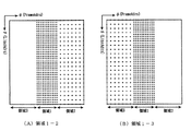
図3は、ビーム走査パターンを説明するための図であり、図3には二つのビーム走査パターンが示されている。つまり、図3(A)は領域1−2のパターンであり、図3(B)は領域1−3のパターンである。 FIG. 3 is a diagram for explaining a beam scanning pattern. FIG. 3 shows two beam scanning patterns. That is, FIG. 3A shows the pattern of the area 1-2, and FIG. 3B shows the pattern of the area 1-3.
図3において、各ビーム走査パターンは、横軸にフレームアドレスφを示して縦軸にラインアドレスθを示している。なお、図3におけるφとθは、各々、図2に示したφとθに対応している。そして、図3に示す各ビーム走査パターン内のドット(黒点)は、超音波ビームが形成されるアドレスを示している。 In FIG. 3, in each beam scanning pattern, the horizontal axis indicates the frame address φ and the vertical axis indicates the line address θ. Note that φ and θ in FIG. 3 correspond to φ and θ shown in FIG. 2, respectively. And the dot (black dot) in each beam scanning pattern shown in FIG. 3 has shown the address where an ultrasonic beam is formed.
図3(A)の領域1−2のパターンは、領域1内においてドットの密度が高い。そして、領域2においてドットの密度が低く、領域3にはドットが存在しない。つまり、領域1−2のパターンにおいて、領域1は超音波ビームが高密度に走査される高密度領域であり、領域2は超音波ビームが低密度に走査される低密度領域であり、領域3は超音波ビームが走査されないブランク領域である。ちなみに、図3(A)において、領域1のドットの密度は領域2のドットの密度の4倍である。
The pattern of the area 1-2 in FIG. 3A has a high dot density in the
これに対し、図3(B)の領域1−3のパターンは、領域1内においてドットの密度が高く、領域3においてドットの密度が低く、領域2にはドットが存在しない。つまり、領域1−3のパターンにおいて、領域1は超音波ビームが高密度に走査される高密度領域であり、領域2は超音波ビームが走査されないブランク領域であり、領域3は超音波ビームが低密度に走査される低密度領域である。
In contrast, the pattern of the area 1-3 in FIG. 3B has a high dot density in the
本実施形態では、これらのビーム走査パターンが交互に選択されて各ビーム走査パターンに応じた走査制御が行われることにより、ブランク領域に対応した空間部分を含む三次元空間内(送受波空間内)の全域に亘って超音波ビームが走査される。そして、送受波空間内の全域から得られる複数のエコーデータに基づいて画像形成処理が実行される。 In the present embodiment, these beam scanning patterns are alternately selected and scanning control is performed in accordance with each beam scanning pattern, whereby a three-dimensional space (in a transmission / reception space) including a space portion corresponding to a blank area is performed. The ultrasonic beam is scanned over the entire area. Then, an image forming process is executed based on a plurality of echo data obtained from the entire area in the transmission / reception space.
図4は、超音波ビームの走査から画像処理用のデータが形成されるまでの処理を説明するための図である。図4において横方向は時間の経過に対応している。つまり、時刻t,時刻t+1,時刻t+2,・・・と時間の経過が示されている。そして、図4において縦方向には各時刻に対応した処理内容が示されている。なお、図4は、あくまでも複数の処理内容の対応関係を示した図であり、例えば、同じ時刻に対応した複数の処理内容が必ずしも同時に進行されるとは限らない。
FIG. 4 is a diagram for explaining processing from scanning of an ultrasonic beam to formation of data for image processing. In FIG. 4, the horizontal direction corresponds to the passage of time. That is, time t,
まず、時刻tにおいてビーム走査パターンとして領域1−2のパターンが選択される。つまり、制御部22は、例えば、予め装置に登録されている領域1−2のパターン(図3(A))を選択する。そして、そのパターンに応じて、送受信部12が超音波ビームを走査する。これにより、領域1から高密度なエコーデータ「領域1(t)」が取得され、領域2から低密度なエコーデータ「領域2(t)」が取得される。領域1(t)と領域2(t)はボリューム合成部14に供給される。
First, at time t, the pattern of the area 1-2 is selected as the beam scanning pattern. That is, the
ボリューム合成部14は、3つのボリュームバッファを備えている。つまり、バッファ1からバッファ3を備えている。そして、時刻tに対応したデータである領域1(t)と領域2(t)が、バッファ1内の各々の記憶領域に書き込まれる。時刻tにおいて領域3に対応するエコーデータは存在しないため、バッファ1内の領域3の部分にはデータが書き込まれない。また、時刻tにおいて、バッファ2とバッファ3にはデータの書き込みが行われない。
The
次に、時刻t+1においてビーム走査パターンとして領域1−3のパターン(図3(B))が選択され、そのパターンに応じて送受信部12が超音波ビームを走査する。これにより、領域1から高密度なエコーデータ「領域1(t+1)」が取得され、領域3から低密度なエコーデータ「領域3(t+1)」が取得される。そして、時刻t+1に対応したデータである領域1(t+1)と領域3(t+1)はボリューム合成部14に供給され、バッファ1とバッファ2に書き込まれる。
Next, at
つまり、バッファ1内の領域1と領域3の記憶領域に、各々、領域1(t+1)と領域3(t+1)が書き込まれる。但し、時刻t+1に対応する領域2のエコーデータは取得されないため、バッファ1内の領域2の記憶領域にはデータの書き込みが行われない。そのため、バッファ1内の領域2のデータは領域2(t)が維持される。また、バッファ2内の領域1と領域3の記憶領域にも、各々、領域1(t+1)と領域3(t+1)が書き込まれる。時刻t+1において、バッファ3にはデータの書き込みが行われない。
That is, region 1 (t + 1) and region 3 (t + 1) are written in the storage regions of
次に、時刻t+2においてビーム走査パターンとして領域1−2のパターンが選択され、そのパターンに応じて、送受信部12が超音波ビームを走査する。これにより、領域1から高密度なエコーデータ「領域1(t+2)」が取得され、領域2から低密度なエコーデータ「領域2(t+2)」が取得される。そして、領域1(t+2)と領域2(t+2)はボリューム合成部14に供給され、バッファ2とバッファ3に書き込まれる。
Next, at
また、時刻t+2において、バッファ1は読み出し用バッファとして機能する。つまり、バッファ1内に記憶されたエコーデータ「領域1(t+1)」「領域2(t)」「領域3(t+1)」が画像処理用のデータ(画像処理データ)として三次元画像形成部16によって読み出される。こうして、三次元画像形成部16は、3つの領域の全てから得られるエコーデータに基づいて画像形成処理を実行する。
At
次に、時刻t+3においてビーム走査パターンとして領域1−3のパターンが選択され、そのパターンに応じて、送受信部12が超音波ビームを走査する。これにより、領域1から高密度なエコーデータ「領域1(t+3)」が取得され、領域3から低密度なエコーデータ「領域3(t+3)」が取得される。そして、領域1(t+3)と領域3(t+3)はボリューム合成部14に供給され、バッファ3とバッファ1に書き込まれる。
Next, at
また、時刻t+3において、バッファ2は読み出し用バッファとして機能する。つまり、バッファ2内に記憶されたエコーデータ「領域1(t+2)」「領域2(t+2)」「領域3(t+1)」が画像処理データとして読み出される。
At
さらに、時刻t+4以降においても、2つのビーム走査パターンが交互に利用され、各ビーム走査パターンに応じて得られるエコーデータが、3つのバッファのうちから循環的に選択される2つのバッファに書き込まれる。また、書き込みが行われない残り1つのバッファからデータが読み出される。こうして、図4に示すように、各時刻ごとに画像処理データが読み出される。 Further, after time t + 4, two beam scanning patterns are alternately used, and echo data obtained in accordance with each beam scanning pattern is written into two buffers that are cyclically selected from the three buffers. . Further, data is read from the remaining one buffer that is not written. Thus, as shown in FIG. 4, the image processing data is read at each time.
図4の時刻t+2から時刻t+5までの画像処理データが示すように、高密度領域である領域1のデータは、各時刻ごとに新しいデータに書き換えられている。また、低密度領域である領域2と領域3のデータは、各々、2時刻に1度だけデータの取得が行われるため、領域2と領域3のエコーデータの収集に要する走査時間を小さくすることができる。つまり、本実施形態では、領域1において高密度に超音波を走査して高空間分解能を実現し、且つ、領域2と領域3における走査時間を小さくして高フレームレートを維持することが可能になる。また、領域2と領域3のうちのいずれか一方のデータは、領域1のデータと同じ時刻のものである。つまり、本実施形態では、同時相内で高密度領域に対応した画像部分と低密度領域に対応した画像部分とを得ることが可能になる。
As shown in the image processing data from time t + 2 to time t + 5 in FIG. 4, the data in the high-
次に、図5および図6を利用して、本実施形態における超音波ビームの走査手順について詳述する。図5は、本実施形態で利用されるビームディレイテーブルの説明図であり、図6は、本実施形態で利用されるビームシーケンステーブルの説明図である。 Next, an ultrasonic beam scanning procedure in this embodiment will be described in detail with reference to FIGS. 5 and 6. FIG. 5 is an explanatory diagram of a beam delay table used in the present embodiment, and FIG. 6 is an explanatory diagram of a beam sequence table used in the present embodiment.
図5に示すビームディレイテーブルは、横軸をラインアドレスθとして縦軸をフレームアドレスφとしている。そして、ビームディレイテーブル上において、ラインアドレスθの値とフレームアドレスφの値によって、♯1から♯1600の各超音波ビームのディレイデータが特定される。各超音波ビームのディレイデータには、その超音波ビームを形成する際に複数の振動素子の各々に与えられる遅延量などのデータが含まれている。
In the beam delay table shown in FIG. 5, the horizontal axis represents the line address θ and the vertical axis represents the frame address φ. On the beam delay table, the delay data of the
ビームディレイテーブルは、例えば、θ方向の走査角、φ方向の走査角、1ボリュームを構成する設定可能最大フレーム数、1フレームを構成する設定可能最大ライン数、診断レンジなどのパラメータから、制御部22によって求められ、装置の初期化時などに制御部22から送受信部12内のメモリなどに設定される。
The beam delay table includes, for example, a control unit based on parameters such as a scanning angle in the θ direction, a scanning angle in the φ direction, the maximum number of frames that can be configured in one volume, the maximum number of lines that can be configured in one frame, and the
さらに、制御部22は、超音波ビームを送受信する順に応じて、ビームシーケンステーブルにビーム番号またはビームアドレスを設定する。図6に示すビームシーケンステーブルには、超音波ビームを送受信する順がビーム番号(♯1〜♯1600)によって設定されている。ビームシーケンステーブルは、先に説明したビーム走査パターンに基づいて設定される。
Furthermore, the
例えば、図3に示すビーム走査パターンが利用される場合には、まず、領域1−2のパターンに応じたビームシーケンスが設定される。つまり、図6に示すように領域1内の複数の超音波ビーム(♯601〜♯1000)がビームシーケンステーブルに設定され、続いて、領域2内の複数の超音波ビーム(♯1001〜♯1600)がビームシーケンステーブルに設定される。
For example, when the beam scanning pattern shown in FIG. 3 is used, first, a beam sequence corresponding to the pattern of the region 1-2 is set. That is, as shown in FIG. 6, a plurality of ultrasonic beams (# 601 to # 1000) in the
そして、領域1−2のパターンに応じたビームシーケンスが設定されると、続いて、領域1−3のパターンに応じたビームシーケンスが設定される。つまり、図6に示すように、領域2に関するビームシーケンスに続けて、領域1内の複数の超音波ビーム(♯601〜♯1000)がビームシーケンステーブルに設定され、続いて、領域3内の複数の超音波ビーム(♯1〜♯600)がビームシーケンステーブルに設定される。
When the beam sequence corresponding to the pattern of the area 1-2 is set, subsequently, the beam sequence corresponding to the pattern of the area 1-3 is set. That is, as shown in FIG. 6, following the beam sequence related to the
なお、領域1は高密度領域であるため、図5のビームディレイテーブル内の領域1に対応する全てのビーム番号が図6のビームシーケンステーブルに設定される。これに対し、領域2と領域3は低密度領域であるため、図5のビームシーケンステーブル内の領域2と領域3に対応した複数のビーム番号のうちの選択されたビーム番号のみが図6のビームシーケンステーブルに設定される。例えば、近接する4つのビームのうちの一つのビームのみが選択される。
Since
超音波の送受信が開始されると、制御部22は、ビームカウンタをスタートさせる。ビームカウンタはそのカウント値を一つずつカウントアップしていく。そして、ビームカウンタのカウント値に応じて、ビームシーケンステーブルの先頭からビーム番号が次々に送受信部12に伝えられる。つまり、図6に示すビームシーケンステーブルの例では、ビーム番号♯601から、♯602,♯603,・・・とビーム番号が次々に送受信部12に伝えられる。
When transmission / reception of an ultrasonic wave is started, the
そして、送受信部12は、ビームシーケンステーブルに従って次々に伝えられるビーム番号を参照して、ビームディレイテーブルからそのビーム番号のディレイデータを読み出して、そのディレイデータに応じて超音波ビームの送受信処理を実行する。こうして、プローブ10から送受波空間内に超音波ビームが走査される。
Then, the transmission /
以上説明したように、本実施形態では、複数のビーム走査パターンを利用して各ビーム走査パターンに応じた走査制御を行うことにより、三次元空間内(送受波空間内)で超音波ビームを走査させている。従って、ビーム走査パターンを変更することにより、様々な超音波ビームの走査態様を実現することができる。図7から図11は、複数のビーム走査パターンであるビーム走査パターンセットの様々な態様を示している。 As described above, in the present embodiment, by performing scanning control according to each beam scanning pattern using a plurality of beam scanning patterns, an ultrasonic beam is scanned in a three-dimensional space (in a transmission / reception space). I am letting. Accordingly, various ultrasonic beam scanning modes can be realized by changing the beam scanning pattern. 7 to 11 show various modes of a beam scanning pattern set that is a plurality of beam scanning patterns.
図7には、ビーム走査パターンセット1〜3が示されている。各ビーム走査パターンセットは、ビーム走査パターンAとビーム走査パターンBの二つのパターンで構成されており、ビーム走査パターンAに応じた走査とビーム走査パターンBに応じた走査が交互に繰り返して実行される。 FIG. 7 shows beam scanning pattern sets 1 to 3. Each beam scanning pattern set is composed of two patterns, a beam scanning pattern A and a beam scanning pattern B, and scanning according to the beam scanning pattern A and scanning according to the beam scanning pattern B are executed alternately and repeatedly. The
なお、図7〜11の各ビーム走査パターンセットで示される各ビーム走査パターン内において、格子縞の部分は超音波ビームが形成される領域を示しており、格子縞の密な部分は高密度領域であり格子縞の粗な部分は低密度領域である。また、格子縞が存在しない空白部分はブランク領域である。 In each of the beam scanning patterns shown in each of the beam scanning pattern sets of FIGS. 7 to 11, the lattice fringes indicate regions where ultrasonic beams are formed, and the dense portions of the lattice fringes are high-density regions. The rough portion of the checkered pattern is a low density region. In addition, a blank portion where no checkered stripe exists is a blank region.
ビーム走査パターンセット1は、先に説明した図3のビーム走査パターンに相当する。また、ビーム走査パターンセット2,3は、中央に形成された高密度領域を環状の低密度領域が取り囲むパターンである。 The beam scanning pattern set 1 corresponds to the beam scanning pattern of FIG. 3 described above. Further, the beam scanning pattern sets 2 and 3 are patterns in which a high density region formed in the center is surrounded by an annular low density region.
図8には、ビーム走査パターンセット4〜7が示されている。図8に示す各ビーム走査パターンセットは、図7のビーム走査パターンセット1〜3と同様に、二つのビーム走査パターンで構成されており、二つのビーム走査パターンの各々に応じた走査が交互に繰り返して実行される。 FIG. 8 shows beam scanning pattern sets 4 to 7. Each beam scanning pattern set shown in FIG. 8 is composed of two beam scanning patterns, similarly to the beam scanning pattern sets 1 to 3 in FIG. 7, and scanning corresponding to each of the two beam scanning patterns is alternately performed. It is executed repeatedly.
図9には、ビーム走査パターンセット8〜10が示されている。各ビーム走査パターンセットは、ビーム走査パターンAとビーム走査パターンBとビーム走査パターンCの三つのパターンで構成されており、ビーム走査パターンA→ビーム走査パターンB→ビーム走査パターンC→ビーム走査パターンA→・・・の順に三つのパターンが順次選択されて各パターンに応じた走査が順次実行される。 FIG. 9 shows beam scanning pattern sets 8 to 10. Each beam scanning pattern set is composed of three patterns: a beam scanning pattern A, a beam scanning pattern B, and a beam scanning pattern C. Beam scanning pattern A → beam scanning pattern B → beam scanning pattern C → beam scanning pattern A Three patterns are sequentially selected in the order of... And scanning corresponding to each pattern is sequentially executed.
図10には、ビーム走査パターンセット11,12が示されている。各ビーム走査パターンセットは、四つのビーム走査パターンで構成されている。例えば、ビーム走査パターンセット11は、ビーム走査パターンAからビーム走査パターンDの四つのパターンで構成されており、ビーム走査パターンA→ビーム走査パターンB→ビーム走査パターンC→ビーム走査パターンD→ビーム走査パターンA→・・・の順に四つのパターンが順次選択されて各パターンに応じた走査が順次実行される。また、ビーム走査パターンセット12についても、それに含まれる四つのパターンが順次選択されて各パターンに応じた走査が順次実行される。 FIG. 10 shows beam scanning pattern sets 11 and 12. Each beam scanning pattern set is composed of four beam scanning patterns. For example, the beam scanning pattern set 11 includes four patterns of a beam scanning pattern A to a beam scanning pattern D. The beam scanning pattern A → beam scanning pattern B → beam scanning pattern C → beam scanning pattern D → beam scanning. Four patterns are sequentially selected in the order of pattern A →... And scanning corresponding to each pattern is sequentially executed. For the beam scanning pattern set 12, four patterns included in the beam scanning pattern set 12 are sequentially selected, and scanning corresponding to each pattern is sequentially executed.
さらに、図11には、ビーム走査パターンセット13,14が示されている。各ビーム走査パターンセットは、四つのビーム走査パターンで構成されている。そして、図10に示したビーム走査パターンセット11,12と同様に、ビーム走査パターンセット13,14は、各々、四つのパターンが順次選択されて各パターンに応じた走査が順次実行される。 Further, FIG. 11 shows beam scanning pattern sets 13 and 14. Each beam scanning pattern set is composed of four beam scanning patterns. Similarly to the beam scanning pattern sets 11 and 12 shown in FIG. 10, in the beam scanning pattern sets 13 and 14, four patterns are sequentially selected, and scanning corresponding to each pattern is sequentially executed.
図7から図11に示したように、ビーム走査パターンセットには様々な態様が存在する。なお、図示したビーム走査パターンセット1〜14のいずれのセットについても、各セットに含まれる一つのビーム走査パターンのブランク領域が他のビーム走査パターンの低密度領域によって埋め合わされている。従って、各パターンに応じた走査が順次実行されることにより、ブランク領域に対応した空間部分を含む三次元空間内の全域に亘って超音波ビームが走査される。 As shown in FIGS. 7 to 11, there are various modes in the beam scanning pattern set. In any of the illustrated beam scanning pattern sets 1 to 14, a blank area of one beam scanning pattern included in each set is filled with a low-density area of another beam scanning pattern. Therefore, by sequentially executing scanning corresponding to each pattern, the ultrasonic beam is scanned over the entire area in the three-dimensional space including the space portion corresponding to the blank area.
以上、本発明の好適な実施形態を説明したが、上述した実施形態は、例えば次のような効果を奏する。本実施形態では、領域1から領域3によって構成される送受波空間の全域を観察しながら、注目すべき領域として領域1内で高空間分解能な画像を形成することが可能になる。
As mentioned above, although preferred embodiment of this invention was described, embodiment mentioned above has the following effects, for example. In the present embodiment, it is possible to form an image with high spatial resolution in the
また、本実施形態では、注目すべき領域1以外の領域2,3については、低密度で且つ2ボリュームに1回ずつエコーデータの収集を行うので、領域2,3のエコーデータ収集に費やす走査時間を小さくすることができ、領域1内における時間分解能を維持しつつ、領域1から領域3によって構成される広い範囲の画像を観察することが可能になる。
Further, in this embodiment, the
なお、上述した実施形態やその効果は、あらゆる点で単なる例示にすぎず、本発明の範囲を限定するものではない。本発明は、その本質を逸脱しない範囲で各種の変形形態を包含する。 In addition, embodiment mentioned above and its effect are only illustrations in all the points, and do not limit the scope of the present invention. The present invention includes various modifications without departing from the essence thereof.
12 送受信部、14 ボリューム合成部、16 三次元画像形成部、22 制御部。 12 transmission / reception unit, 14 volume composition unit, 16 three-dimensional image forming unit, 22 control unit.
Claims (4)
超音波ビームを介して三次元空間内から得られる複数のエコーデータに基づいて、対象組織を三次元的に表現した超音波画像の画像データを形成する画像形成手段と、
を有し、
前記各ビーム走査パターンは、ビーム密度が高い高密度領域とビーム密度が低い低密度領域とを含む、
ことを特徴とする超音波診断装置。 A transmission / reception unit that scans an ultrasonic beam in a three-dimensional space including the target tissue by sequentially selecting a plurality of beam scanning patterns and performing scanning control according to each beam scanning pattern;
Image forming means for forming image data of an ultrasonic image representing the target tissue three-dimensionally based on a plurality of echo data obtained from the three-dimensional space via an ultrasonic beam;
Have
Each of the beam scanning patterns includes a high density region having a high beam density and a low density region having a low beam density.
An ultrasonic diagnostic apparatus.
前記各ビーム走査パターンは、高密度領域と低密度領域とに加えて超音波ビームが走査されないブランク領域を含み、
前記複数のビーム走査パターンが順次選択されて各ビーム走査パターンのブランク領域が他のビーム走査パターンの低密度領域によって埋め合わされることにより、ブランク領域に対応した空間部分を含む三次元空間内の全域に亘って超音波ビームが走査される、
ことを特徴とする超音波診断装置。 The ultrasonic diagnostic apparatus according to claim 1,
Each of the beam scanning patterns includes a high-density region and a low-density region, and a blank region where the ultrasonic beam is not scanned,
The plurality of beam scanning patterns are sequentially selected, and blank areas of each beam scanning pattern are filled with low-density areas of other beam scanning patterns, so that the entire area in the three-dimensional space including a spatial portion corresponding to the blank area An ultrasonic beam is scanned over
An ultrasonic diagnostic apparatus.
前記複数のビーム走査パターンが順次選択されて複数のビーム走査パターンの高密度領域が互いに重ね合わされることにより、高密度領域に対応した空間部分において、超音波ビームの高密度走査が経時的に維持される、
ことを特徴とする超音波診断装置。 The ultrasonic diagnostic apparatus according to claim 2,
The plurality of beam scanning patterns are sequentially selected and the high-density regions of the plurality of beam scanning patterns are overlapped with each other, so that the high-density scanning of the ultrasonic beam is maintained over time in the space corresponding to the high-density region. To be
An ultrasonic diagnostic apparatus.
画像データを形成するにあたり、高密度領域に対応した画像部分と低密度領域に対応した画像部分との間のビーム密度差を補う補間処理を行う、
ことを特徴とする超音波診断装置。
The ultrasonic diagnostic apparatus according to claim 1,
In forming the image data, an interpolation process is performed to compensate for the beam density difference between the image portion corresponding to the high density region and the image portion corresponding to the low density region.
An ultrasonic diagnostic apparatus.
Priority Applications (1)
| Application Number | Priority Date | Filing Date | Title |
|---|---|---|---|
| JP2006263967A JP4851288B2 (en) | 2006-09-28 | 2006-09-28 | Ultrasonic diagnostic equipment |
Applications Claiming Priority (1)
| Application Number | Priority Date | Filing Date | Title |
|---|---|---|---|
| JP2006263967A JP4851288B2 (en) | 2006-09-28 | 2006-09-28 | Ultrasonic diagnostic equipment |
Publications (2)
| Publication Number | Publication Date |
|---|---|
| JP2008079885A JP2008079885A (en) | 2008-04-10 |
| JP4851288B2 true JP4851288B2 (en) | 2012-01-11 |
Family
ID=39351330
Family Applications (1)
| Application Number | Title | Priority Date | Filing Date |
|---|---|---|---|
| JP2006263967A Expired - Fee Related JP4851288B2 (en) | 2006-09-28 | 2006-09-28 | Ultrasonic diagnostic equipment |
Country Status (1)
| Country | Link |
|---|---|
| JP (1) | JP4851288B2 (en) |
Families Citing this family (5)
| Publication number | Priority date | Publication date | Assignee | Title |
|---|---|---|---|---|
| KR100949059B1 (en) * | 2006-10-17 | 2010-03-25 | 주식회사 메디슨 | Ultrasound system and method for forming ultrasound image |
| EP2575625B1 (en) * | 2010-05-26 | 2014-05-14 | Koninklijke Philips N.V. | High image rate 3d ultrasonic diagnostic imaging |
| JP5844353B2 (en) * | 2010-05-26 | 2016-01-13 | コーニンクレッカ フィリップス エヌ ヴェKoninklijke Philips N.V. | High volume rate 3D ultrasound imaging of the heart |
| JP2012196255A (en) * | 2011-03-18 | 2012-10-18 | Fujifilm Corp | Ultrasound diagnostic apparatus and method of producing ultrasound image |
| EP2607895A1 (en) * | 2011-12-21 | 2013-06-26 | Siemens Aktiengesellschaft | Phased array scans with selectable resolution |
Family Cites Families (5)
| Publication number | Priority date | Publication date | Assignee | Title |
|---|---|---|---|---|
| JPH1033535A (en) * | 1996-07-30 | 1998-02-10 | Toshiba Corp | Doppler ultrasonograph and its method |
| JP4382374B2 (en) * | 2003-03-12 | 2009-12-09 | アロカ株式会社 | Ultrasonic diagnostic equipment |
| JP2004290249A (en) * | 2003-03-25 | 2004-10-21 | Fuji Photo Film Co Ltd | Ultrasonic imaging apparatus and ultrasonic imaging method |
| JP2005152346A (en) * | 2003-11-26 | 2005-06-16 | Aloka Co Ltd | Ultrasonic diagnostic system |
| JP4730889B2 (en) * | 2005-07-26 | 2011-07-20 | 日立アロカメディカル株式会社 | Ultrasonic imaging system |
-
2006
- 2006-09-28 JP JP2006263967A patent/JP4851288B2/en not_active Expired - Fee Related
Also Published As
| Publication number | Publication date |
|---|---|
| JP2008079885A (en) | 2008-04-10 |
Similar Documents
| Publication | Publication Date | Title |
|---|---|---|
| JP4969985B2 (en) | Ultrasonic diagnostic apparatus and control program for ultrasonic diagnostic apparatus | |
| JP5283875B2 (en) | Ultrasonic diagnostic apparatus and control program for ultrasonic diagnostic apparatus | |
| JP5844353B2 (en) | High volume rate 3D ultrasound imaging of the heart | |
| JP5770189B2 (en) | Ultrasonic diagnostic equipment | |
| JP5134787B2 (en) | Ultrasonic diagnostic apparatus, ultrasonic image processing apparatus, and ultrasonic image processing program | |
| KR101100464B1 (en) | Ultrasound system and method for providing three-dimensional ultrasound image based on sub region of interest | |
| JP5438012B2 (en) | Ultrasonic diagnostic equipment | |
| WO2014010683A1 (en) | Ultrasonic inspection device | |
| US20130303913A1 (en) | Three-dimensional ultrasonic imaging methods and systems | |
| JP2007020908A (en) | Ultrasonic diagnostic equipment and control program of ultrasonic diagnostic equipment | |
| WO2010024023A1 (en) | Ultrasound diagnostic apparatus and method of displaying ultrasound image | |
| JP4851288B2 (en) | Ultrasonic diagnostic equipment | |
| JP4740695B2 (en) | Ultrasonic diagnostic equipment | |
| JP5965898B2 (en) | High volume rate 3D ultrasound imaging | |
| JPH11113902A (en) | Ultrasonograph and ultrasonography | |
| JP5058638B2 (en) | Ultrasonic diagnostic equipment | |
| JP2013165922A (en) | Ultrasonic diagnostic apparatus | |
| JP5331313B2 (en) | Ultrasonic diagnostic equipment | |
| JP3619425B2 (en) | Ultrasonic diagnostic equipment | |
| JP2005118081A (en) | Ultrasonic diagnostic apparatus | |
| JP5348829B2 (en) | Ultrasonic diagnostic apparatus, ultrasonic image display method, and ultrasonic image display program | |
| JP5395611B2 (en) | Ultrasonic diagnostic apparatus, image data generation apparatus, and control program for image data generation | |
| JP4987503B2 (en) | Ultrasonic diagnostic apparatus, image data display apparatus, and image data display control program | |
| JP5989735B2 (en) | Ultrasonic image processing apparatus, program, and ultrasonic image processing method | |
| JP6132665B2 (en) | Ultrasonic diagnostic equipment |
Legal Events
| Date | Code | Title | Description |
|---|---|---|---|
| A621 | Written request for application examination |
Free format text: JAPANESE INTERMEDIATE CODE: A621 Effective date: 20090727 |
|
| A977 | Report on retrieval |
Free format text: JAPANESE INTERMEDIATE CODE: A971007 Effective date: 20110727 |
|
| A131 | Notification of reasons for refusal |
Free format text: JAPANESE INTERMEDIATE CODE: A131 Effective date: 20110802 |
|
| A521 | Written amendment |
Free format text: JAPANESE INTERMEDIATE CODE: A523 Effective date: 20110913 |
|
| TRDD | Decision of grant or rejection written | ||
| A01 | Written decision to grant a patent or to grant a registration (utility model) |
Free format text: JAPANESE INTERMEDIATE CODE: A01 Effective date: 20111018 |
|
| A01 | Written decision to grant a patent or to grant a registration (utility model) |
Free format text: JAPANESE INTERMEDIATE CODE: A01 |
|
| A61 | First payment of annual fees (during grant procedure) |
Free format text: JAPANESE INTERMEDIATE CODE: A61 Effective date: 20111020 |
|
| R150 | Certificate of patent or registration of utility model |
Free format text: JAPANESE INTERMEDIATE CODE: R150 |
|
| FPAY | Renewal fee payment (event date is renewal date of database) |
Free format text: PAYMENT UNTIL: 20141028 Year of fee payment: 3 |
|
| R250 | Receipt of annual fees |
Free format text: JAPANESE INTERMEDIATE CODE: R250 |
|
| R250 | Receipt of annual fees |
Free format text: JAPANESE INTERMEDIATE CODE: R250 |
|
| S111 | Request for change of ownership or part of ownership |
Free format text: JAPANESE INTERMEDIATE CODE: R313111 |
|
| R350 | Written notification of registration of transfer |
Free format text: JAPANESE INTERMEDIATE CODE: R350 |
|
| LAPS | Cancellation because of no payment of annual fees |