JP4851280B2 - Image processing apparatus and method of using image processing apparatus - Google Patents
Image processing apparatus and method of using image processing apparatus Download PDFInfo
- Publication number
- JP4851280B2 JP4851280B2 JP2006251835A JP2006251835A JP4851280B2 JP 4851280 B2 JP4851280 B2 JP 4851280B2 JP 2006251835 A JP2006251835 A JP 2006251835A JP 2006251835 A JP2006251835 A JP 2006251835A JP 4851280 B2 JP4851280 B2 JP 4851280B2
- Authority
- JP
- Japan
- Prior art keywords
- latch member
- image processing
- opening
- processing apparatus
- hole
- Prior art date
- Legal status (The legal status is an assumption and is not a legal conclusion. Google has not performed a legal analysis and makes no representation as to the accuracy of the status listed.)
- Expired - Fee Related
Links
Images


Landscapes
- Control Or Security For Electrophotography (AREA)
- Facsimiles In General (AREA)
- Accessory Devices And Overall Control Thereof (AREA)
Description
本発明は、画像処理装置、画像処理装置の使用方法に関する。 The present invention relates to an image processing apparatus and a method of using the image processing apparatus.
近年、小型の携帯型記憶媒体(リムーバブルメモリメディア)が普及し、文書や撮影した画像等の記憶手段として利用されている。このようなリムーバブルメモリメディアとしては、例えば、スマートメディア、DVD(Didital Video Disk)、CD−R(Compact Disc Recordable)、CD―RW(Compact Disc Rewritable)、コンパクトフラッシュ(登録商標)、マルチメディアカード(MMC)、SDカード(Secure Digital)、メモリスティック等の各種記憶メディアがある。これらの記憶メディアに記憶されたデータを読み込んで所定枚数の画像出力をするプリント機能を備えた画像処理装置が店舗等に設置され、一般に使用可能になってきている。 In recent years, small portable storage media (removable memory media) have become widespread and are used as storage means for documents and captured images. Examples of such removable memory media include smart media, DVD (Digital Video Disk), CD-R (Compact Disc Recordable), CD-RW (Compact Disc Rewritable), Compact Flash (registered trademark), multimedia card ( There are various storage media such as MMC), SD card (Secure Digital), and memory stick. An image processing apparatus having a print function for reading data stored in these storage media and outputting a predetermined number of images is installed in a store or the like and is generally available.
一方、記憶メディアをメディアインターフェースに着脱可能に装着してデータの入出力を行う場合、途中で記憶メディアの脱落や引き抜き等が発生するのを防止するために、メディアインターフェース部に開閉型のカバーを取り付ける例がある。例えば、デジタルカメラ等の撮像装置で撮影された写真画像の画像データを記憶する記憶メディアが挿入口から挿入されると読み取って印刷出力する画像プリント装置で当該挿入口に開閉自在のカバーを設けた画像プリント装置の例がある(例えば、特許文献1、2参照)。
On the other hand, when a storage medium is detachably attached to the media interface and data is input / output, an open / close type cover is provided on the media interface to prevent the storage medium from dropping or pulling out during the process. There is an example to attach. For example, an image printing apparatus that reads and prints out when a storage medium that stores image data of a photographic image taken by an imaging device such as a digital camera is inserted through the insertion port is provided with an openable / closable cover at the insertion port. There is an example of an image printing apparatus (for example, see
画像処理装置としては、コピー機能、ファクシミリ機能(FAX機能)、プリント機能及びスキャナー機能を複合したMFP(Multi Function Peripheral)と称されるデジタル複合機が提供されている。
また、デジタルカラー複合機であって、半導体メディア等の記憶媒体に記憶されている画像データ等を読み取り、記憶媒体に対して画像データ等を書き込む外部メディア入出力装置を搭載したものがある(例えば、特許文献3参照)。
As an image processing apparatus, a digital multifunction peripheral called MFP (Multi Function Peripheral) in which a copy function, a facsimile function (FAX function), a print function, and a scanner function are combined is provided.
Also, there are digital color multifunction peripherals equipped with an external media input / output device that reads image data and the like stored in a storage medium such as a semiconductor medium and writes the image data and the like to the storage medium (for example, And Patent Document 3).
近年の画像処理装置では、携帯型記憶媒体のコネクターを装備したリムーバブルメモリメディアリーダー又はリムーバブルメモリメディアライターを搭載し、これらリムーバブルメモリメディアリーダー又はリムーバブルメモリメディアライターに装着された携帯型記憶媒体に記憶された情報をプリント出力したり、スキャナー機能により読み込んだ原稿情報や、キー操作で作成した文書データを携帯型記憶媒体に記憶させることも可能である。 In recent image processing apparatuses, a removable memory media reader or a removable memory media writer equipped with a connector for a portable storage medium is mounted, and stored in a portable storage medium attached to the removable memory media reader or the removable memory media writer. It is also possible to print out the printed information, and store the original information read by the scanner function and the document data created by the key operation in the portable storage medium.
携帯型記憶媒体は、リムーバブルメモリメディアリーダー又はリムーバブルメモリメディアライターのコネクターに直接、差し込んで使用するためユーザーは物理的には自由に抜き差し可能である一方、アクセス中に抜き取るとデータ破損やOS(Operating System)の動作に支障をきたすという問題がある。 The portable storage medium is directly plugged into the connector of the removable memory media reader or removable memory media writer so that the user can physically insert and remove it freely. There is a problem that the operation of System) is hindered.
前記したように、記憶メディアの脱落や引き抜き等が発生するのを防止するために、メディアインターフェース部に開閉型のカバーを取り付ける例があるが、該カバーを開けることによりアクセス中でも簡単に記憶メディアの取り外しが行われてしまう可能性がある。 As described above, there is an example in which an open / close type cover is attached to the media interface unit in order to prevent the storage medium from dropping or pulling out. However, by opening the cover, the storage medium can be easily accessed even during access. There is a possibility of removal.
本発明は、一定の場合に携帯型記憶媒体を覆う開閉カバーを自由に開けることができないように、携帯型記憶媒体に対する情報の書き込み又は情報の読み出し中など、アクセス中での携帯型記憶媒体の抜き取りを禁止し、データ破損やOSの動作に支障をきたさないようにした画像処理装置、画像処理装置の使用方法を提供することを課題とする。 The present invention provides a portable storage medium that is being accessed, such as when information is being written to or read from the portable storage medium, so that the open / close cover that covers the portable storage medium cannot be freely opened in certain cases. It is an object of the present invention to provide an image processing apparatus and a method of using the image processing apparatus that are prohibited from being extracted and that do not interfere with data corruption or OS operation.
前記課題を達成するため請求項1にかかる発明は、リムーバブルメモリメディアリーダー又はリムーバブルメモリメディアライターを搭載した画像処理装置であって、前記リムーバブルメモリメディアリーダー又は前記リムーバブルメモリメディアライターに装着された携帯型記憶媒体を覆う開閉カバーと、少なくとも前記携帯型記憶媒体に対する情報の書き込み中又は情報の読み出し中は該開閉カバーが開けられるのを阻止する開き動作阻止手段を具備し、
この開き動作阻止手段は、前記開閉カバーの側面部に設けられた穴又は凹部と、この穴又は凹部と嵌合可能なラッチ部材を備え、前記ラッチ部材を前記穴又は凹部に嵌合させる向きに付勢する付勢手段と、
前記付勢手段による前記ラッチ部材の移動を前記嵌合位置で止めるラッチ部材用ストッパと、
前記ラッチ部材を前記穴又は凹部に嵌合させ、また、嵌合を解除する係脱方向に移動可能に案内するラッチ部材案内手段と、
前記ラッチ部材に形成された嵌合穴に出入りする方向に往復動可能な可動軸部を具備したラッチ部材ロック・解除用の電磁駆動手段と、
前記ラッチ部材ロック・解除用の電磁駆動手段を前記係脱方向に移動可能に案内する電磁駆動手段案内手段と、
前記ラッチ部材ロック・解除用の電磁駆動手段を前記ラッチ部材の付勢方向と同じ方向に付勢する第2の付勢手段と、
前記第2の付勢手段による前記ラッチ部材ロック・解除用の電磁駆動手段の移動を前記可動軸部が前記嵌合穴に対峙する位置で停止させる電磁駆動手段用ストッパと、
ラッチ部材ロック・解除用の電磁駆動手段と一体的に移動する取っ手とを具備した。
請求項2にかかる発明は、請求項1に記載の画像処理装置において、
前記ラッチ部材及び前記ラッチ部材ロック・解除用の電磁駆動手段は指より小さい径の小孔が形成された保護カバーの内側に配置され、前記取っ手は前記保護カバーの外側に配置され、前記小孔から挿入される操作棒で前記ラッチ部材を押し動かすことができ、この押動動作により、前記ラッチ部材が前記穴部又は前記凹部に嵌合した状態のもとで、前記穴又は凹部に対する前記ラッチ部材による嵌合状態の解除を可能とした。
請求項3にかかる発明は、請求項1又は2に記載の画像処理装置において、
前記ラッチ部材には、前記操作棒により押し動かされる方向を前記ラッチ部材による前記開閉カバーに対する嵌合状態の解除方向に変換する傾斜面が形成されていることとした。
請求項4にかかる発明は、請求項1乃至3の何れかに記載の画像処理装置において、
前記ラッチ部材を前記穴又は凹部に嵌合させる向きに付勢する付勢手段と、
前記付勢手段による前記ラッチ部材の移動を前記嵌合位置で止めるラッチ部材用ストッパと、
前記ラッチ部材を前記穴又は凹部に嵌合させ、また、嵌合を解除する係脱方向に移動可能に案内するラッチ部材案内手段と、
前記ラッチ部材に形成された係止部に出入りする方向に往復動可能な可動軸部を具備したラッチ部材ロック・解除用の電磁駆動手段と、
前記ラッチ部材を、前記穴又は凹部から嵌合解除させる向きに押動させる押動部材とを具備することとした。
請求項5にかかる発明は、請求項1乃至4の何れかに記載の画像処理装置において、
前記開閉カバーと係合可能であり、前記リムーバブルメモリメディアリーダー又は前記リムーバブルメモリメディアライターの下方に位置する往復動部材と、
前記往復動部材を前記開閉カバーに係合させる向きに付勢する付勢手段と、
前記往復動部材を前記開閉カバーに係合させ、また、係合を解除する係脱方向に移動可能に案内するラッチ部材案内手段と、
前記往復動部材の移動を規制および規制解除する方向に往復動可能な可動軸部を具備した前記往復動部材規制用の電磁駆動手段とを具備することとした。
請求項6にかかる発明は、リムーバブルメモリメディアリーダー又はリムーバブルメモリメディアライターを備え、これらリムーバブルメモリメディアリーダー又はリムーバブルメモリメディアライターに携帯型記憶媒体を装着して画像処理を行う画像処理装置の使用方法であって、
前記携帯型記憶媒体を開閉カバーで覆い、前記開閉カバーに設けた穴部又は凹部に、保護カバーで覆われたラッチ部材を嵌合させることにより前記開閉カバーをロック状態にし、該ロック状態を解除する際には前記保護カバーの外部に設けた取っ手と一体的に前記嵌合解除方向に可動の電磁駆動手段の可動軸部を前記ラッチ部材に係合させて、前記取っ手及び前記電磁駆動手段と共に前記ラッチ部材を前記嵌合解除方向に移動可能とし、
少なくとも前記携帯型記憶媒体に対するデータ読み出し又は書き込み中には、前記電磁駆動手段の動作により前記可動軸部の前記ラッチ部材に対する嵌合を解除することにより前記取っ手の動きが前記ラッチ部材に伝わらないようにして前記取っ手を空送り状態にし、取っ手の操作による前記ロック状態の解除を不能にして前記開閉カバーが開けられるのを阻止することとした。
請求項7にかかる発明は、請求項6に記載の画像処理装置の使用方法において、
前記携帯型記憶媒体に対するデータ読み出し又は書き込み前又は後には、前記電磁駆動手段の動作により前記可動軸部を前記ラッチ部材に嵌合させることにより前記取っ手と前記ラッチ部材の連結状態を得て、取っ手の操作による前記ロック状態の解除を可能にすることとした。
In order to achieve the above object, an invention according to
The opening operation blocking means includes a hole or a recess provided in a side surface portion of the opening / closing cover, and a latch member that can be fitted to the hole or the recess, and is adapted to fit the latch member into the hole or the recess. A biasing means for biasing;
A latch member stopper for stopping movement of the latch member by the biasing means at the fitting position;
Latch member guide means for fitting the latch member into the hole or recess and guiding the latch member so as to be movable in a disengagement direction for releasing the fitting;
An electromagnetic drive means for latch member locking / releasing comprising a movable shaft portion reciprocally movable in a direction of entering and exiting a fitting hole formed in the latch member;
Electromagnetic drive means guide means for guiding the latch member lock / release electromagnetic drive means to be movable in the engagement / disengagement direction;
A second biasing means for biasing the electromagnetic driving means for locking and releasing the latch member in the same direction as the biasing direction of the latch member;
A stopper for electromagnetic driving means for stopping movement of the electromagnetic driving means for locking and releasing the latch member by the second urging means at a position where the movable shaft portion faces the fitting hole;
An electromagnetic driving means for locking / releasing the latch member and a handle that moves integrally are provided.
The invention according to
The latch member and the electromagnetic driving means for locking / releasing the latch member are disposed inside a protective cover in which a small hole having a diameter smaller than a finger is formed, and the handle is disposed outside the protective cover. The latch member can be pushed and moved by an operation rod inserted from the base, and the pushing operation allows the latch member to be latched with respect to the hole or the recess under a state in which the latch member is fitted into the hole or the recess. The fitting state by the member can be released .
The invention according to
Wherein the latch member, and a Rukoto been inclined surface formed to convert the direction of pushed by the operating rod in the release direction of the fitted state with respect to the cover by the latch member.
The invention according to claim 4 is the image processing apparatus according to any one of
A biasing means for biasing the latch member in a direction to fit the hole or the recess;
A latch member stopper for stopping movement of the latch member by the biasing means at the fitting position;
Latch member guide means for fitting the latch member into the hole or recess and guiding the latch member so as to be movable in a disengagement direction for releasing the fitting;
An electromagnetic drive means for latch member locking / releasing comprising a movable shaft portion capable of reciprocating in a direction to move in and out of a locking portion formed in the latch member;
The latch member is provided with a pushing member that pushes the latch member in a direction to release the fitting from the hole or the recess .
The invention according to
A reciprocating member that is engageable with the open / close cover and is located below the removable memory media reader or the removable memory media writer;
Biasing means for biasing the reciprocating member in a direction to engage the opening / closing cover;
Latch member guide means for engaging the reciprocating member with the opening / closing cover and for movably guiding the engagement member to disengage the engagement;
It was that it comprises an electromagnetic driving means for the reciprocating member restrainer provided with the reciprocable movable shaft moves in a direction to restrict and regulate releasing of the reciprocating member.
The invention according to
Cover the portable storage medium with an open / close cover, and lock the open / close cover by fitting a latch member covered with a protective cover into a hole or recess provided in the open / close cover. When doing so, the movable shaft portion of the electromagnetic drive means movable in the fitting release direction integrally with the handle provided outside the protective cover is engaged with the latch member, together with the handle and the electromagnetic drive means. The latch member is movable in the fitting release direction,
At least during reading or writing of data with respect to the portable storage medium, the movement of the handle is not transmitted to the latch member by releasing the fitting of the movable shaft portion to the latch member by the operation of the electromagnetic driving means. Thus, the handle is set to the idle feed state, and the unlocked state by the operation of the handle is disabled to prevent the opening / closing cover from being opened .
The invention according to
Before or after reading or writing data to or from the portable storage medium, the movable shaft portion is engaged with the latch member by the operation of the electromagnetic driving means to obtain a connected state of the handle and the latch member, and the handle it was decided to allow the release of the locked state by the operation.
この発明は、携帯型記憶媒体を覆う開閉カバーを自由に開けることができないようにして、携帯型記憶媒体に対する情報の書き込み又は情報の読み出し中など、アクセス中での携帯型記憶媒体の抜き取りを禁止し、データ破損やOSの動作に支障をきたさないようにした画像処理装置、画像処理装置の使用方法を提供することができる。 The present invention prohibits removal of the portable storage medium during access, such as writing information to or reading information from the portable storage medium, so that the open / close cover that covers the portable storage medium cannot be freely opened. In addition, it is possible to provide an image processing apparatus and a method for using the image processing apparatus that do not impair data corruption or OS operation.
以下に、この発明の実施の形態を説明する。
[1]例1
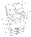
本発明にかかる画像処理装置の外観を図1、図2に示す。この画像処理装置1は、コピー機能、ファクシミリ機能(FAX機能)、プリント機能及びスキャナー機能を複合したデジタル複合機である。装置の最上部にはスキャナー2及び原稿搬送部3が位置している。
原稿搬送部3の原稿載置部3aに載置された原稿は自動送り中にスキャナー2で読み取られ、原稿排紙部3bに排出される。スキャナー2で読み取られた情報は、画像処理装置1の中段部に位置するプリンター4でシート状媒体にプリントすることができるし、また、FAX機能により希望の送信先へ送信することができる。プリントされたシート状媒体は排紙部6に排出される。
Embodiments of the present invention will be described below.
[1] Example 1
The external appearance of the image processing apparatus according to the present invention is shown in FIGS. The
The document placed on the
装置の最下部に位置する給紙部5は4段にわたるシート状媒体の収納領域を有し、各段の給紙トレイに異なるサイズ或いは種類のシート状媒体が収納され、画像形成プロセスの適時のタイミングでプリンター4にシート状媒体を供給する。
The
スキャナー2および原稿搬送部3はユニットとして構成されていて、図示しない透明板からなる原稿載置台の上部に載置されており、この原稿載置台に接する部位は柔軟に変形してコピー原稿を覆う弾性材からなる圧板になっている。
原稿載置台の下方には原稿を走査する走査手段が設けられていて、厚手の原稿などコピー原稿を露光走査して撮像素子に読み取り情報を取り込み、プリンター4でシート状媒体にプリントすることができる。
The
A scanning unit that scans the document is provided below the document placement table, and a copy document such as a thick document can be exposed and scanned to read information into the image sensor, and can be printed on a sheet-like medium by the printer 4. .
画像処理装置1の最上部であって、画像処理装置の操作者と相対する側には原稿搬送部3と隣接して操作部10がある。操作部10には、画像処理装置を操作するのに必要な各種操作キー7、スイッチ釦8、タッチキーなどスイッチ機能、情報表示機能をもつ操作パネル11等が配置されている。また、携帯型記憶媒体を覆う開閉カバー12がある。図2において、画像形成装置1の前面に対面したときの、操作部10の左方は排紙部6のうち、天井部分が抜けた排出確認領域6aになっている。
At the top of the
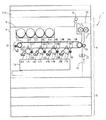
画像処理装置1のうち、プリンター4は電子写真方式により画像形成を行う画像形成機能を有する。その概略の構成及び画像形成プロセスを説明する。
本体ケース9内部の略中央部には、4つの作像部13(13Y、13C、13M、13K)と、光ビームを出射する光書込装置14と、中間転写ベルト15とが配置されている。各作像部13はそれぞれ異なる色の画像(トナー像)を形成する部分である。各作像部13の構成部品等に関し、本明細書及び図面の記載において、数字の後に付したY、C、M、Kの添え字は、各作像部に対応する各々イエロー、シアン、マゼンタ、ブラックの色を示している。
Of the
Four image forming units 13 (13Y, 13C, 13M, and 13K), an
4つの作像部13Y、13C、13M、13Kは、使用するトナーの色が異なるために形成される画像の色が異なるだけで、基本的な構造は同じである。各作像部13は、矢印方向へ回転駆動される感光体16(16Y、16C、16M、16K)、感光体16の周囲に配置された帯電部17、現像部18、クリーニング部19等により構成されている。
The four image forming units 13Y, 13C, 13M, and 13K have the same basic structure except that the colors of the formed images are different because the colors of the toners used are different. Each image forming unit 13 includes a photosensitive member 16 (16Y, 16C, 16M, 16K) that is rotationally driven in the direction of an arrow, a charging unit 17, a developing
感光体16は、円筒状に形成され、駆動源(図示せず)により回転駆動される。感光体16の外周面部には感光層が設けられており、感光体16の表面である外周面16aは被走査面とされている。光書込装置14から出射された光ビームが感光体16の外周面16aにスポット照射されることにより、感光体16の外周面16aには画像情報に応じた静電潜像が書き込まれる。
The photoconductor 16 is formed in a cylindrical shape and is rotationally driven by a drive source (not shown). A photosensitive layer is provided on the outer peripheral surface portion of the photoconductor 16, and the outer
帯電部17は、感光体16の外周面16aを一様に帯電するもので、感光体16に対して非接触方式のものが採用されている。現像部18は、感光体16へのトナーの供給を行い、供給されたトナーが感光体16の外周面16aに書き込まれた静電潜像に付着することにより感光体16上の静電潜像をトナー像として顕像化させるもので、感光体16に対して非接触方式のものが採用されている。
The charging unit 17 uniformly charges the outer
クリーニング部19は、感光体16の外周面16aに付着している残留トナーをクリーニングするもので、感光体16の外周面6aにブラシを接触させるブラシ接触方式のものが採用されている。
The
中間転写ベルト15は、樹脂フィルム又はゴムを基体として形成されたループ状のベルトで、感光体16上に形成されたトナー像が転写される。この中間転写ベルト15は、ローラにより支持されて矢印方向へ回転駆動される。
The
中間転写ベルト15の内周面側(ループの内側)には、各感光体16上のトナー像を中間転写ベルト15上に転写させるために中間転写ベルト15を感光体16に押圧する4個の転写ローラ24が配置されている。中間転写ベルト15の外周面16a側(ループの外側)には、中間転写ベルト15の外周面16aに付着した残留トナーや紙粉等をクリーニングするクリーニング部25が配置されている。
On the inner peripheral surface side (inside the loop) of the
給紙部5の4つの給紙トレイ中の何れかから分離給紙されたシート状媒体が搬送経路26を辿り、レジストローラ27を経て中間転写ローラ29、定着部30、排紙ローラ31の順に搬送される。
A sheet-like medium separated and fed from one of the four paper feed trays of the
レジストローラ29は、所定のタイミングで間欠的に回転駆動されるローラである。このレジストローラ29が間欠的に回転駆動されることにより、レジストローラ29の位置まで搬送されて停止していたシート状媒体が、中間転写ベルト15と中間転写ローラ29とにより挟まれる転写位置へ送り込まれ、この転写位置において中間転写ベルト15上のトナー像がシート状媒体に転写される。
The
定着部30は、シート状媒体上に転写されたトナー像に熱と圧力とを加えて定着させる部分である。定着部30内を通過する過程においてトナー像が定着されたシート状媒体は、排紙ローラ31により排紙部6に排紙される。
The fixing
図3に示した画像処理装置おいて、排紙部6の上方に位置する符号310で示した領域は、コピー原稿を露光走査する露光走査装置を配置する部位であり、さらにこの領域310の上方の符号32で示した領域は、図1、図2におけるスキャナー2や原稿搬送部3等が配置される領域である。
In the image processing apparatus shown in FIG. 3, an area denoted by
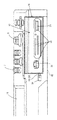
図1、図2に示した画像処理装置1の構成部分のうち、操作部10を取り出して示した図4、図5において、ユーザーは操作キー7によりコピー枚数の決定やスタートを行う。
操作キー7の下には操作基板32があって操作キー7等の押下を検知する。これら操作キー7や操作パネル11、スイッチ等の操作釦8等コピー枚数の決定やスタート指示を行うための操作手段を載せた操作基板32は奥側よりも前側が低くなるように水平面に対して傾斜して設けられている。これは、前側に対面して操作する操作者の操作性を良好にするためである。
In FIGS. 4 and 5 in which the
There is an
つまり、操作基板32は操作基板32に付帯して設けられた上記操作手段を操作する操作者に近い側(前側)が、操作者から遠い側(奥側)よりも低くなるように傾斜して設置されている。さらに、携帯型記憶媒体33を着脱可能に装着するコネクター34を備えたリムーバブルメモリメディアリーダー35は前記操作基板32の下方にて、操作者に近い側(前側)が操作者から遠い側(奥側)よりも高くなるように傾斜して設置されている。
つまり、リムーバブルメモリメディアリーダー35は操作基板32とは逆向きに傾斜して設けている。
That is, the
That is, the removable
これに対して、第1の比較例では図6に示すように、リムーバブルメモリメディアリーダー35を操作基板32の下方にて、操作者に近い側(前側)と操作者から遠い側(奥側)とで同じ高さになるように図5における位置とコネクター34の位置を変えずに、該コネクター部34を中心に回転した状態で比較した場合、リムーバブルメモリメディアリーダー35の前側端部が開閉カバー12にぶつかるようになる。したがって、操作部10の寸法を2点鎖線で示すように、前側に拡張しなければならなくなる。
On the other hand, in the first comparative example, as shown in FIG. 6, the removable
また、第2の比較例では図7に示すように、リムーバブルメモリメディアリーダー35を操作基板32の下方にて、操作者に近い側(前側)が操作者から遠い側(奥側)に対して低くなるように図5における位置とコネクター34の位置を変えずに、該コネクター部34を中心に回転した状態で比較した場合、リムーバブルメモリメディアリーダー35の前側端部が下に向くため該リムーバブルメモリメディアリーダー35のコネクター34に対する着脱時の操作性が著しく悪化する。操作性を改善するには、操作部10の寸法を2点鎖線で示すように、下側に拡張しなければならなくなる。
In the second comparative example, as shown in FIG. 7, the removable
なお、本明細書における画像処理装置1では、リムーバブルメモリメディアリーダー35に代えて、リムーバブルメモリメディアライターが搭載されることもあるが、図ではリムーバブルメモリメディアリーダー35を備えた例を示している。
In the
画像処理装置1は床面積を小さくしたいという要求があり、図6に2点鎖線で示したように操作部10はあまり前側に飛び出させることはできない。手前側に大きく飛び出すと操作部10が操作者の身体にあたってスキャナー2の操作性が悪くなるばかりか、図2に示した排出領域6aを縮めてしまうので、印刷を終えて排紙部6にでてきたシート状媒体の存在を確認しずらくなる。
The
これに対して、図5に示した例では、操作部10の幅(前側から奥側に向かう方向での幅寸法)を図6、図7の例に比べて小さくすることができ、リムーバブルメモリメディアリーダー又はリムーバブルメモリメディアライターおよび操作基板32が配置される操作部領域は、当該画像処理装置1から出力されるシート状記録媒体の排出を確認するために設けた排出確認領域6aに隣接して配置されているので、排紙部6に排出されたシート状媒体を確認するための排出確認領域6aを確保することができるので、排出されるシート状媒体の視認性が向上する。
On the other hand, in the example shown in FIG. 5, the width (width dimension in the direction from the front side to the back side) of the
本例ではリムーバブルメモリメディアリーダー又はリムーバブルメモリメディアライターを奥側に傾斜させて操作基板32と奥側が重なるように設置したので小型化が可能である。また、操作基板32及び操作キーなどの操作手段は画像処理装置1の上部の上面部に儲けられていることと相俟って、リムーバブルメモリメディアリーダー又はリムーバブルメモリメディアライターの前側(操作者にとっての手前側)が上向けになることでコネクター34が位置する奥を見やすくなるため、開閉カバー12を開いた状態での携帯型記憶媒体33の抜き差し時の操作性も向上する。図5において、携帯型記憶媒体33の抜き差し方向は双方向矢印で示した方向である。
In this example, the removable memory media reader or the removable memory media writer is inclined so that the
図8において、リムーバブルメモリメディアリーダー35に装着された携帯型記憶媒体33を覆う開閉カバー12が開いた状態を示している。開閉カバー12は任意の支点、本例ではコネクター34の上方部に設けた支点軸O―Oを中心に揺動自在である。支点軸O―Oを中心に揺動して開閉する構成としたので、スライド式開閉カバーに比べ直線的な移動ない分、スペースを有効利用できる。また、回転動作で迅速な開閉が可能である。
FIG. 8 shows a state in which the opening /
開閉カバー12は内部の携帯型記録媒体の有無を外部から視認可能の透明部を有することし、本例では全体を透明として携帯型記録媒体の装着を外部から視認できるようにした。
リムーバブルメモリメディアリーダー又はリムーバブルメモリメディアライターの下方に位置する下部構造体(本例では保護カバー42の一部として構成される)は、画像形成装置の胴内に位置する排紙部6に排紙されるシート状媒体を視認可能なように、全体若しくはその一部が透明になっている。開閉カバー12が透明であるので、これらを透かして排紙部6における排紙の状況を視認することができる。
開閉カバー12は携帯型記憶媒体33に対する情報の書き込み中又は情報の読み出し中は該開閉カバー12が開くのを、開き動作阻止手段により防止している。
かかる開き動作阻止手段の働きにより、携帯型記憶媒体に対する情報の書き込み又は情報の読み出し中など、アクセス中での携帯型記憶媒体の抜き取りを禁止し、データ破損やOSの動作に支障をきたさないようにした。
The opening /
The lower structure (configured as a part of the
The opening /
With the function of the opening operation prevention means, the portable storage medium is not allowed to be removed during access such as writing information to or reading information from the portable storage medium, so that data is not damaged or the operation of the OS is not hindered. I made it.
開閉カバー12は支点軸O―Oを中心にして自重モーメントで閉じ状態を維持し、操作者が開閉カバーの一部を手で掴んで持ち上げることにより開くことができるが、例えば、支点軸O―Oに捩りコイルバネなどを装着することにより開放方向に付勢して開き習性の構成とすることもできる。
The open /
開き習性の構成とした場合には、前記開き動作阻止手段によるロックを解除することによりリムーバブルメモリメディアリーダー33(又は前記リムーバブルメモリメディアライター)からの携帯型記憶媒体33の取り外しが可能な状態まで自動的に開いた位置で、適宜に設けたストッパに当接することで回動を止める。この場合、操作者は開閉カバー12の一部を手で掴んで開ける操作を必要としない。
In the case of an open behavior configuration, the
開き動作阻止手段による開閉カバーの開放阻止機能は、画像処理装置1の電源オフ時において解除可能とした。開き動作阻止手段を電動駆動とした場合、電源オフ時には開き動作阻止手段を駆動することができず、ロック状態の場合、携帯型記憶媒体33の取り出しが不能となるのでは不便である。そこで、電源オフ時でも開き動作阻止手段によるロックを解除することを可能にしている。電源オフ時には、携帯型記憶媒体に対する情報の読み書きは中断されているので、開き動作阻止手段による開閉カバー12のロックを解除し、携帯型記憶媒体の抜き出しを行っても問題はない。このロック解除機構については後述する。
The function of preventing the opening / closing cover from being opened by the opening operation preventing means can be canceled when the
上記したように電源オフ時には前記開き動作阻止手段は自動解除されるが、それ以外で操作者が任意に開閉カバー12を開きたいときには、操作キー7を操作する。或いは、操作パネル11に表示されるタッチキーを操作する。画像処理装置1の制御部は、少なくとも携帯型記憶媒体に対する情報の書き込み中又は情報の読み出し中は、かかるキー操作が行われても前記開き動作阻止手段を解除しない。これにより、携帯型記憶媒体の抜き出しが阻止され安全が維持される。なお、操作者に対しては、操作パネル11に開閉カバー12が開かない理由を表示する。
As described above, when the power is turned off, the opening operation prevention means is automatically released. Otherwise, the operator operates the
以下、開閉カバーの開き阻止手段について説明する。
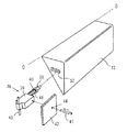
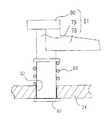
図9において、開き動作阻止手段36は、開閉カバー12の側面部に設けられた穴(又は凹部:以下同様)37と、この穴37と嵌合可能なラッチ部材38を具備する。図10に示すように、ラッチ部材38を穴37に嵌合させた状態では開閉カバー12を開けることができない。よって、携帯型記憶媒体33に対する情報の書き込み中又は情報の読み出し中はラッチ部材38を穴37に嵌合させた状態にすることで、操作者が誤って携帯型記憶媒体33をコネクター34から取り出すことを阻止することができる。また、情報の書き込み又は情報の読み出しを終えたらラッチ部材38を穴37から外すこと(嵌合解除)により。コネクター34に対する携帯型記憶媒体33の着脱が可能である。
The opening / closing cover opening preventing means will be described below.
In FIG. 9, the opening operation blocking means 36 includes a hole (or a recess: the same applies hereinafter) 37 provided in the side surface of the opening /
穴37に対するラッチ部材38の嵌合、嵌合解除は、ラッチ部材38を往復動させることで行う。この往復動をさせる手段として、開閉カバーロック・解除用の電磁駆動手段を用いた。本例では、開閉カバーロック・解除用の電磁駆動手段として電磁ソレノイド39を使用している。ラッチ部材38は、電磁ソレノイド39の動作軸部(通電のオン、オフにより往復動する軸体)と一体的に構成している。電磁ソレノイド39を使用することで、スイッチ操作により容易に開閉カバー12の開き動作の阻止及びその解除を行うことができる。
The
ラッチ部材38と一体的に構成された動作軸部40は該電磁ソレノイド39に対する通電オフの状態では伸長性のばね41の弾性により電磁ソレノイド本体から突出する習性を有し、通電をオンにするとばね41の弾性に勝る電磁力により引かれて引っ込む。
The operating
このように、電磁ソレノイド39に対する通電がオフの時にラッチ部材38が穴37に嵌合状態になるように動作軸部40(本例では、動作軸部40とラッチ部材38は一体)はばね41により付勢されて突出し、該嵌合状態で電磁ソレノイド38に組み込まれた適宜のストッパ手段によって突出を停止している。
Thus, the operating shaft portion 40 (in this example, the operating
こうしてラッチ部材38が穴37に嵌合状態となっている状態のもとで、電磁ソレノイド39に対する通電がオンされた時に、電磁力によってばね41の付勢力に抗して動作軸部40が引かれることにより、前記嵌合が解除される。
When the energization of the
図10は通電をオフにした状態を示し、ラッチ部材38が穴37に嵌合して開閉カバー12の開放を阻止している。通電をオンにするとラッチ部材38は穴37から引っ込み、開閉カバー12の開き動作を可能にする。手で開けることができるし、開き方向に付勢されている場合には、その付勢力で自動的に開く。
FIG. 10 shows a state in which the energization is turned off, and the
例えば、開閉カバー12が開き方向に付勢されている構成では、この付勢力により開閉カバー12が開こうとしても穴37とラッチ部材38とが嵌合しているため開閉カバー12を開くことができない。ラッチ部材38と穴37は常には嵌合を保つように付勢されていてソレノイド32を駆動してラッチ部材38を引っ張ると嵌合が解除されてカバー16が開く。
For example, in the configuration in which the opening /
電磁ソレノイド39は画像処理装置1の本体側に支持されている。例えば、操作キー7或いは操作パネル11のタッチキーを操作することで、電磁ソレノイド39に対する通電のオン、オフを行うことができる。
The
開閉カバー12が閉じられていて、かつ、電磁ソレノイド39に対する通電オフの状態のもとで緊急に開閉カバー12を開ける必要がある場合のロック解除機構を説明する。
図9において、電磁ソレノイド39は指より小さい径の小孔44が形成された保護カバー42(図1参照)の内側に配置されている。
The unlocking mechanism when the opening /
In FIG. 9, the
電磁ソレノイド39は、ラッチ部材38の往復動方向と交差する上下方向に長い支点軸43を中心に一体的に揺動可能である。支点軸43は画像処理装置1の本体部に枢着されている。電磁ソレノイド39は外力の作用で揺動可能であるが、外力が無くなったら原位置に復帰させる。この原位置復帰の手段として、図11に示すように支点軸43をばね45、46で直径方向に引くようにしている。これにより、支点軸43は外力で捩られても、外力がなくなると原位置に復帰する。かかる原位置にあるときに、ラッチ部材38は閉じ状態にある開閉カバー12の側面に形成された穴37に嵌合可能である。
The
穴37は、該ラッチ部材の揺動方向である横方向に長い長穴形状をしている。かかる穴37にラッチ部材38が嵌合している状態のもとで、保護カバー42に形成した小孔44より横方向から挿入される操作棒47で外力を作用されて電磁ソレノイド39を押し動かし、支点軸43を中心に揺動させることができる。
The
かかる揺動により、ラッチ部材38は穴37の長手方向に移動して穴37から外れ、穴37に対するラッチ部材38による穴37に対する嵌合状態が解除される。すなわち、緊急時には、操作棒47で電磁ソレノイド39の側部を押動して開き動作阻止手段による開閉カバー12の開き動作阻止機能を解除することができる。こうして、開閉カバー12を開いた後、操作棒47を小孔44から引き抜くと、電磁ソレノイド39は支点軸43の復元機能により原位置に復帰する。
By such swinging, the
開閉カバー12を開き、携帯型記憶媒体33の着脱動作など行ったのち、開閉カバー12を閉じる際には、ラッチ部材38の先端部が斜面(テーパ)になっているので、ばね41の力に抗して該斜面が開閉カバー12の端部に乗り上げ、摺動し、開閉カバー12を完全に閉じたときに、穴37に嵌合される。
After the opening /
このように、緊急時、例えば画像処理装置の動作が停止した場合や停電になった場合に、小孔44から挿入される操作棒47の操作で外部から電磁ソレノイド39を押し動かすことができ、この押動動作により、ラッチ部材38が穴37に嵌合した状態のもとで、穴37に対するラッチ部材38による嵌合状態を解除し、開閉カバー12を開くことが可能である。保護カバー42における小孔44の部分は操作棒47のガイド機能をはたすようにある程度の厚みを付すようにするとよい。
電磁ソレノイドは各種あり、通電のオン、オフにより上記と逆も動作を行うものもあるが、勿論そのようなタイプのものを使用することもできる。
Thus, in an emergency, for example, when the operation of the image processing apparatus is stopped or a power failure occurs, the
There are various types of electromagnetic solenoids. Some electromagnetic solenoids operate in the opposite direction when energization is turned on and off. Of course, those types can also be used.
画像処理装置1では一般に、通電オフになっている時間や、通電オフとなる頻度が高いので通電オフでラッチ部材38による穴37への嵌合状態となるタイプの電磁ソレノイドでは、部品の消耗度合いが小さくなる利点がある。
In general, in the
本例の開閉カバー12及び電磁ソレノイド39、操作棒47挿入用として保護カバー42に形成された穴44などを操作部10と共に図12に示す。
また、直接カバーの開閉を阻止するのではなく、以下のようにユーザーのロック解除動作を規制するように構成することもできる。
FIG. 12 shows the opening /
Further, instead of directly blocking the opening and closing of the cover, it is possible to restrict the user's unlocking operation as follows.
[2]例2
ケース1
図13乃至図17を参照しつつ説明する。
開閉カバー12は支点軸O−Oを中心に揺動して開閉可能である。図13に示した開閉カバー12は閉じ位置にあり、開くときには支点軸O−Oを中心にして矢印で示す反時計回りの向きに回動する。支点軸O−Oと同心の軸部70には捩りコイルばね71が装着されていて、該ねじりコイルばね71の一端部が開閉カバー12の縁部に、他端部が図示しないばねストッパにそれぞれ係止されており、開閉カバー12を開き方向に付勢している。
[2] Example 2
This will be described with reference to FIGS.
The open /
開閉カバー12の支点軸O−O方向の一方の側面部(図13に示した側部)には矩形の穴72(或いは凹部でもよい)が形成されている。図3に示した状態では、この穴72にラッチ部材73が嵌入している。ラッチ部材73は保護カバー42の一部として構成された取り付け板74に装着されている。
A rectangular hole 72 (or a recess may be formed) is formed in one side surface portion (side portion shown in FIG. 13) of the opening /
ここで、取り付け板74に対するラッチ部材73の装着態様を説明する。取り付け板74はその上面レベルが閉位置にある開閉カバー12の穴72の高さ位置と合っている。取り付け板74の上面であって穴72と対向した部位には、支点軸O−Oと平行に案内溝74aが形成されている。案内溝74aそのものの形状は図14、図15に示すように矩形の貫通孔である。
Here, how the
図13に示したラッチ部材73を説明の都合上、裏返して示した図16において、該ラッチ部材73の底部には案内溝74aに摺動可能に嵌合できる大きさの駒部材73aが一体形成されている。さらに、駒部材73aの底面には、ねじ76を用いて、抜け止め板75が固定されている。駒部材73aの支点軸O−O方向上での長さは、案内溝74aよりも小さい。よって、駒部材73aは案内溝74a内を往復動可能である。このようにして、ラッチ部材73は案内溝74aに案内されて所定のストロークで往復動可能である。所定のストロークとは、ラッチ部材73が開閉カバー12側に移動して穴72内に入った開閉カバー係止位置と、穴72の外部に退避した退避位置との間の距離をいう。
In FIG. 16, the
案内溝74a内には伸長性のばね77が組み込まれている。ばね77は駒部材73aと案内溝74aの長手方向端部との間に介在して、ラッチ部材73を常に、開閉カバー12へ向けて付勢している。
An
図13において、ばね77で付勢されたラッチ部材73は穴72に入った状態で開閉カバー係止位置で止まっている。このため、開閉カバー12は、開き習性を有するものの、ラッチ部材73により開き動作を阻止されている。開閉カバー12を開くためには、ラッチ部材73を退避位置に移動させねばならない。
In FIG. 13, the
ラッチ部材73を退避位置に移動させるための手段を説明する。ラッチ部材73は、図13、図16に示すようにくさび形をしている。つまり、図13に示すように、支点軸O−Oの方向上、開閉カバー12に近づくにつれて先細りとなる傾向に上片部が傾斜した傾斜面73bを有している。
A means for moving the
傾斜面73bの上方には押動片78が位置している。押動片78は軸部79及び押釦80と一体的に構成され、全体として押圧部材81を構成している。軸部79は取り付け板74に形成した貫通穴82(図13、図14、図17参照)を摺動可能に貫通嵌合している。軸部79はその底部に抜け止め部材83が固定されて抜け止めされている。軸部79の中間部には、鍔状をしたばね受け84が固定されている。このばね受け84と取り付け板74との間には軸部79を巻くようにして伸長性のばね85が装着されている。
A
このばね85の付勢力により、押釦80に外力が作用しない状態では、図13に示すように押動片78は傾斜面73bから離れた上方に位置している。開閉カバー12を開く必要があるとき、押釦80を押し下げると、押動片78が傾斜面73bに当接し、かつ、斜面に作用するよこ方向の分力によりラッチ部材73は、ばね77の弾性に抗して退避位置に移動する。これにより、開閉カバー12は捩りコイルばね71の弾性により、図13に示した矢印の向きに開く。
In a state where no external force is applied to the
開閉カバー12は図示しないストッパで係止される位置まで開いて止まる。また、押釦80は押すことを止めれば、押動片78は、ばね85の弾性により傾斜面73bの上方に復帰する。この位置では、抜け止め部材83が取り付け板74に当接している。
The opening /
開閉カバー12が開いた状態では、ラッチ部材73は開閉カバー係止位置まで前進しており、開閉カバー12の側縁部の閉じ動作経路上に位置している。この状態のもとで開閉カバー12を閉じる動作がなされると、やがて該開閉カバー12の側縁部が傾斜面73bに当接するようになり、さらに、傾斜面に作用する横方向の分力でラッチ部材73が押し動かされ、該ラッチ部73の先端部が開閉カバー12の側面部にばね77の弾性力で摺動する。やがて、ラッチ部材73と穴72とが合致するようになると該穴72にラッチ部材72が嵌入し、開閉カバー12が閉じ位置で保持される。
When the open /
このように、手動作で開閉カバー12を閉じると、予め定めた所定の閉じ位置でラッチ部材73が自動的に穴72に係合して閉じ状態が保持され、押釦81を押動することで開閉カバー12を開くことができる。なお、押釦80の押動、復帰動作を繰り返すうちに、軸部79が貫通穴82内で回動すると押動片78が傾斜面73bから外れてしまうので、これを避けるために、軸部79と貫通穴82間にキーとキー溝を設けるなどして、適宜の回り止め手段を講ずることは勿論である。
As described above, when the open /
かかる構成のもとで、携帯型記憶媒体に対する情報の書き込み中又は情報の読み出し中は該開閉カバー12が開けられるのを阻止する開き動作阻止手段を構成した。
取り付け板74上面に電磁ソレノイド86を取り付けている。図14に示した4つのねじ穴87は電磁ソレノイド86の取り付けねじ穴であり、図示のように、電磁ソレノイド86はラッチ部材73の近傍に位置する。
Under such a configuration, the opening operation blocking means is configured to block the opening /
An
電磁ソレノイド86の可動軸部86aは、電磁ソレノイド86が通電オンの状態で電磁力いより引っ込んでおり、通電オフで可動軸部86aに設けたばねの力で突出する。開閉カバー12が閉じ状態(開閉カバー係止位置)のもとで、電磁ソレノイド86を通電オフにすると、可動部材86aが図13に示した引っ込み位置から図示しない突出位置まで突出する。突出した状態では、可動部材86aはラッチ部材73の後壁部(係止部)73cと交差する。これにより、可動軸部86aがラッチ部材73の動きをロックする。
なお、ラッチ部材73に穴又は凹部を形成しておき、これに可動軸部86aを嵌入させてロックするようにすることも可能である。
The
It is also possible to form a hole or a recess in the
従って、通電オフ状態では、ラッチ部材73は機械的にロックされており、押釦80を押動しても、ロックを解除することができない。ロックを解除するには、電磁ソレノイド86を通電オンにすればよい。このように、電磁ソレノイド86に対する通電状態を制御することにより、携帯型記憶媒体に対する情報の書き込み中又は情報の読み出し中は該開閉カバーが誤って開けられるのを阻止することができる。
Therefore, in the energized off state, the
かかる構成において、ばね77は、ラッチ部材73を穴72(又は凹部)に嵌合させる向きに付勢する付勢手段の一例である。駒部材73a及び案内溝74aは、ばね77によるラッチ部材73の移動を穴72(又は凹部)に嵌合した位置で止めるラッチ部材用ストッパの一例である。また、駒部材73a及び案内溝74aは、ラッチ部材73を穴72(又は凹部)に嵌合させ、また、嵌合を解除する係脱方向に移動可能に案内するラッチ部材案内手段の一例である。電磁ソレノイド86は、ラッチ部材73に形成された係止部(後壁部73c、或いは穴、凹部でも可)に出入りする方向に往復動可能な可動軸部86aを具備したラッチ部材ロック・解除用の電磁駆動手段の一例である。押動部材81はラッチ部材73を、穴72(又は凹部)から嵌合解除させる向きに押動させる押動部材の一例である。
In such a configuration, the
ケース2
図18乃至図22を参照しつつ説明する。
開閉カバー12は支点軸O−Oを中心に揺動して開閉可能である。図18に示した開閉カバー12は閉じ位置にあり、開くときには支点軸O−Oを中心にして矢印で示す反時計回りの向きに回動する。支点軸O−Oと同心の軸部70には図示しないが前記ケース1で説明したと同様の捩りコイルばね71が装着されていて、開閉カバー12を開き方向に付勢している。
This will be described with reference to FIGS.
The open /
開閉カバー12は既に説明したように、リムーバブルメモリメディアリーダー又はリムーバブルメモリメディアライターに装着された携帯型記憶媒体を覆っている。開閉カバー12の下方には透明な筐体状をした容器からなる引き出し状の往復動部材90が位置している。
As described above, the opening /
往復動部材90は保護カバー42に形成された凹字型の案内溝91に嵌合しており、矢印92で示す係脱方向に規制された方向に出し入れすることができる。また、往復動部材の底部に形成した凸条が保護カバー42の蟻溝95に係合しているため、往復動部材90は上方に持ち上がることなく上記係脱方向に往復動可能である。
The reciprocating
開閉カバー12の往復動部材90との接合部であって支点軸O−O方向の中央部にはフック部93が構成されている。また、往復動部材90にはフック部93と対応する部位に、フック部93と係合する係合部94が構成されている。
A
図19乃至図21は、フック部93及び係合部94を通り、かつ、支点軸O−Oと直交する断面を示している。図19は図18に対応し開閉カバー12が閉じた状態にある。図10乃至図21において開閉カバー12は伸長性のばね940により左行する向きに付勢されている。
19 to 21 show cross sections that pass through the
図19において、鉤部93が係合部94に係合している。開閉カバー12は本来、軸部70を支点にして回動可能であるが、図19の状態では、ばね940の弾性で係合部93が鉤部93に食い込む傾向に付勢されているため係合は解除されず、開閉カバー12は閉じ状態を維持している。
In FIG. 19, the
図19に示した状態のもとにおいて、往復動部材90を保護カバー42に押し込む向きの右行方向に加圧すると、往復動部材90は保護カバー42に対して右行するので、図20に示すように鉤部93が係合部84から外れて係合が解除される。係合が解除されると、開閉カバー12は開き習性を有するので図20に矢印で示す方向に開く。
In the state shown in FIG. 19, when the reciprocating
保護カバー12を閉じる場合には、保護カバー12を手動作で図20に示した矢印の向きと逆向きに回動させれば、鉤部93が係合部94に掛かり、図19に示すように開閉カバー12の閉じ状態が保持される。
When the
このように、開閉カバー12が閉じ状態では、往復動部材90を押し込めば、鉤部93と係合部94の係合が解除されて開閉カバー12を開くことができるし、開閉カバー12を閉じれば、この閉じ動作に連動して自動的に鉤部93に係合部94が係合して閉じ状態が保持される。
In this way, when the opening /
かかる構成のもとで、携帯型記憶媒体に対する情報の書き込み中又は情報の読み出し中は該開閉カバー12が開けられるのを阻止する開き動作阻止手段を構成した。開閉カバー12が閉じ状態にあり、往復動部材90の係合部94に鉤部93が掛かっている状態のもとで、往復動部材90の後端部の外側直近の往復動部材90スライド面に電磁ソレノイド96を設置した。
Under such a configuration, the opening operation blocking means is configured to block the opening /
電磁ソレノイド90の通電オンの状態では、可動軸部96aは往復動部材90の移動を妨げない高さ位置に引っ込んでいる(図19、図20)。開閉カバー12が閉じ状態にあるときに、電磁ソレノイド90の通電オフにすると、可動軸部96に設けたばね97の力で可動軸部96は図21に示したように突出して往復動部材90の移動を妨げる。これにより、誤って開閉カバー12を開こうと思い、往復動部材90を押し動かそうとしても動かず、よって、誤操作を防止することができる。電磁ソレノイド90の通電オンにすると可動軸部96が引っ込むので往復動部材90を押し動かし、開閉カバー12を開くことができる。
When the
図22に電磁ソレノイド90を拡大して示した。保護カバー42に可動軸部96出入り用の開口98を設け、この開口部98の座部をばね受け99に当てて可動軸部96のストッパとすることができる。
FIG. 22 shows the
このように、電磁ソレノイド96に対する通電状態を制御することにより、携帯型記憶媒体に対する情報の書き込み中又は情報の読み出し中は該開閉カバーが誤って開けられるのを阻止することができる。
In this manner, by controlling the energization state of the
以上の如く、リムーバブルメモリメディアリーダー又はリムーバブルメモリメディアライターの下方に位置する往復動部材90は開閉カバー12の鉤部93と係合可能である。ばね940は往復動部材90を開閉カバー12に係合させる向きに付勢する付勢手段である。蟻溝95及びこの蟻溝95に嵌合している往復動部材の一部は往復動部材90を開閉カバー12に係合させ、また、係合を解除する係脱方向に移動可能に案内するラッチ部材案内手段の一例である。電磁ソレノイド96は往復動部材90の移動を規制および規制解除する方向に往復動可能な可動軸部96aを具備した往復動部材規制用の電磁駆動手段の一例である。
As described above, the reciprocating
これらの構成とすることで、特に開閉カバー12が解放方向に付勢されている装置の場合、ユーザーの意思とは無関係に開閉カバー12が開いてしまうのを防ぐことができる。
With these configurations, it is possible to prevent the opening /
ケース3
本例は、開き動作阻止手段の別例であり、図23乃至図27を参照して説明する。なお、共通の構成部材にはこれまでと同じ符号で説明する。
前記例1とは異なり、本例における開き動作阻止手段360では、ラッチ部材48は電磁ソレノイドとは別体である。ラッチ部材48はブロック状の形をしていて、開閉カバー12の側面に設けられた穴(又は凹部:以下同様)49に嵌合するくさび形の先端部48aを有している。ラッチ部材48は閉じ状態にある開閉カバー12の穴49に嵌合させる向きに付勢する付勢手段としての伸長性のばね50で付勢されている。
This example is another example of the opening operation preventing means, and will be described with reference to FIGS. The common constituent members will be described with the same reference numerals as before.
Unlike the first example, in the opening operation preventing means 360 in this example, the
ばね50によるラッチ部材48の移動を穴49への嵌合位置で止めるラッチ部材用ストッパ51が画像処理装置本体と一体的な部材に設けられている。
図示しないが、ラッチ部材48を穴49に嵌合させ、また、嵌合を解除する係脱方向55A、55Bに移動可能に案内するラッチ部材案内手段がある。このラッチ部材案内手段はラッチ部材48に形成した凸状部と、この凸状部に嵌合する上記係脱方向に長い溝で構成される。この溝は画像処理装置本体と一体的な部材に形成されている。
A
Although not shown, there is a latch member guiding means for fitting the
ラッチ部材48の上面には嵌合穴52(図24参照)が形成されている。ラッチ部材48の上方には嵌合穴52に出入りする方向(上下方向)に往復動可能な可動軸部53を具備したラッチ部材ロック・解除用の電磁駆動手段としての電磁ソレノイド54が配置されている。可動軸部53は伸長性のばね60によって突出方向に付勢されている。
A fitting hole 52 (see FIG. 24) is formed in the upper surface of the
電磁ソレノイド54を係脱方向55に移動可能に案内する電磁駆動手段案内手段がある。この電磁駆動手段案内手段は図示しないが、電磁ソレノイド54に形成した凸状部と、この凸状部に嵌合する上記係脱方向に長い溝で構成されている。この溝は画像処理装置本体と一体的な部材に形成されている。
There is electromagnetic drive means guide means for guiding the
電磁ソレノイド54をばね50によるラッチ部材48の付勢方向と同じ方向に付勢する第2の付勢手段としてのばね56がある。このばね56による電磁ソレノイド54の移動を、可動軸部53がストッパ51で止められたラッチ部材48の嵌合穴52に対峙する位置で停止させる電磁駆動手段用のストッパ57が画像処理装置本体と一体的な部材に設けられている。
電磁ソレノイド54と一体的に移動する取っ手58が、係脱方向55と平行な溝59にその一部を摺動可能に嵌合させて設けられている。
There is a
A
図13に示すように、開閉カバー12が閉じ状態にあり、電磁ソレノイド54への通電オフの状態で可動軸部53が嵌合穴52に嵌合している状態のもとで、操作者は開閉カバー12を開きたい時には取っ手58を溝59に沿って開閉カバー12から離れる向きに動かす。すると、取っ手58と一体となったソレノイド54とソレノイド54の可動軸部53と略嵌合しているラッチ部材48が開閉カバー12から離れる向きに動く。これにより、ラッチ部材48の穴49に対する嵌合が解除されることで、開き動作阻止手段の開き動作阻止す開閉カバー12を開くことが可能となる。
As shown in FIG. 13, the operator opens the open /
一方、図24に示すように、携帯型記憶媒体33に対するデータの読み出し中或いは書き込み中には、電磁ソレノイド54に通電オンとし、電磁ソレノイド32を駆動してばね60の弾性に抗して可動軸部53を引っ込める。すると、可動軸部53とラッチ部材48との嵌合が外れる。
On the other hand, as shown in FIG. 24, during reading or writing of data to / from the
この状態では、携帯型記憶媒体33に対するデータの読み出し中或いは書き込み中に、操作者が誤って開閉カバー12を開こうと、取っ手58を動かした場合、可動軸部53とラッチ部材48との嵌合が外れているので、取っ手58と電磁ソレノイド54とがばね56に逆らって矢印55Bの方向に移動するが、ラッチ部材48はばね50の力により開閉カバー12の穴49との嵌合を保持し続け開閉カバー12を開けることはできない。すなわち取っ手58は空振りし、開閉カバー12の開き動作は阻止された状態となり、データ破損やOSの動作に支障をきたす事態を回避できる。なお、取っ手58以外に電磁ソレノイド54と一体に動く部材を保護カバー42の表側に露出しない構成としておく。
In this state, when the operator accidentally moves the
開閉カバー12が閉じられていて、かつ、電磁ソレノイド54に対する通電オンの状態のもとでは、上記のように取っ手58が空振りしてラッチ部材48の先端部48aを穴49から抜くことができない。そこで、緊急に開閉カバー12を開ける必要がある場合のロック解除機構を説明する。
When the open /
ラッチ部材48を上から見た図を示した図25において、ラッチ部材48及び電磁ソレノイド54は指より小さい径の小孔61が形成された保護カバー42の内側に配置され、取っ手58保護カバー42外側に配置され、前記小孔61から挿入される操作棒(例えばクリップを伸ばしたもの)62でラッチ部材48を押し動かすことができるようにしてある。この押動動作により、ラッチ部材48が穴49に嵌合した状態のもとで、穴49に対するラッチ部材48による嵌合状態の解除を可能としている。
また、カバーを開ける(メディアを取り出すと)問題がある場合には取っ手が空振りするように構成することで、ロックがかかっているのか、単に動き(すべり)が悪くなっているのかがユーザーが明確に分かり、無理に力を加えて破損させる事がなくなる。
In FIG. 25 showing the top view of the
Also, if there is a problem of opening the cover (when the media is removed), the user can clearly see whether the handle is locked or the movement (slip) is getting worse by configuring the handle so that it swings empty. It is understood that it will not be damaged by applying force.
すなわち、ラッチ部材48には、操作棒62により押し動かされる方向をラッチ部材48による開閉カバー12に対する嵌合状態の解除方向(係脱方向55B)に変換する傾斜面48bを形成した。
That is, the
緊急時、例えば画像処理装置の動作が停止した場合や停電になった場合には、小孔61から操作棒62を挿入して傾斜面48bを押し動かすことによりラッチ部品48をばね50の力に逆らって矢印Bの方向に移動させる。この移動により開閉カバー12の穴49からラッチ部材48の先端部48aを抜くことで嵌合を解除し、開閉カバー12を開けることができるようになる。保護カバー42における小孔61の部分は操作棒62のガイド機能をはたすようにある程度の厚みを付すようにするとよい。
In an emergency, for example, when the operation of the image processing apparatus stops or when a power failure occurs, the
このように、携帯型記憶媒体33を開閉カバー12で覆い、開閉カバー12に設けた穴部49又は凹部に、保護カバー42で覆われたラッチ部材48の先端部48aを嵌合させることにより開閉カバー12をロック状態にし、該ロック状態を解除する際には保護カバー12の外部に設けた取っ手58と一体的に嵌合解除方向(係脱方向)に可動の電磁ソレノイド54の可動軸部53をラッチ部材48に嵌合或いは係合させて、取っ手58及び電磁ソレノイドと共にラッチ部材48を前記嵌合解除方向に移動可能とし、少なくとも携帯型記憶媒体に対するデータ読み出し又は書き込み中には、前記電磁ソレノイドの動作により可動軸部53のラッチ部材48に対する嵌合を解除することにより取っ手58の動きがラッチ部材48に伝わらないようにして取っ手58を空振り(空送り)状態にし、取っ手58の操作による前記ロック状態の解除を不能にして開閉カバー12が開けられるのを阻止することで画像処理装置及び携帯型記憶媒体の安全が保持される。
As described above, the
また、携帯型記憶媒体33に対するデータ読み出し又は書き込み前又は後には、前記電磁ソレノイド54の動作により可動軸部53をラッチ部材に嵌合させることにより取っ手58とラッチ部材48の連結状態を得て、取っ手58の操作による前記ロック状態の解除を可能にすることができる。
本発明では、携帯型記憶媒体はコネクターに直接差して使用するためユーザーは自由に抜き差し可能である一方、アクセス中に抜き取るとデータ破損やOSの動作に支障をきたすという問題に対して、開閉カバーとそのロック機構を設けることによりアクセス中のリムーバブルメモリメディア抜き取りを制限することで解決した。また、リムーバブルメモリメディアリーダー又はリムーバブルメモリメディアライターとそのカバーを設置しても画像処理装置全体の床面積が大きくならないよう小型化したいという要求、特に操作部については排紙の視認性を確保するため装置幅方向を小型化したい要求に対して操作キーの基板を手前に傾斜して設置しリムーバブルメモリメディアリーダー又はリムーバブルメモリメディアライター部を奥に傾斜させて基板と奥が重なるように配置したので装置、特に操作部の小型化を可能にしたと同時に操作性をも向上させた。
また、緊急時にはリムーバブルメモリメディアをメカ的に取り出す手段を提供したので装置全体の機能が停止した場合や停電状態に陥った場合でも携帯型記憶媒体の回収を可能にした。
In addition, before or after reading or writing data to or from the
In the present invention, since the portable storage medium is directly inserted into the connector and used by the user, the user can freely insert / remove, while the open / close cover prevents the problem of data corruption or troubles in the OS operation when removed during access. And a lock mechanism to limit the removal of removable memory media being accessed. In addition, in order to ensure the visibility of discharged paper, particularly for the operation unit, it is necessary to reduce the size so that the floor area of the entire image processing apparatus does not increase even if a removable memory media reader or removable memory media writer and its cover are installed. Since the operation key board is tilted forward and the removable memory media reader or removable memory media writer section is tilted back and the board overlaps with the back in response to the demand for downsizing the device width direction, the device Especially, the operation part can be downsized and the operability is improved.
In addition, in the event of an emergency, a means for mechanically removing the removable memory medium is provided, so that the portable storage medium can be recovered even when the function of the entire apparatus is stopped or a power failure occurs.
1 画像処理装置
7 操作キー
8 スイッチ釦
10 操作部
11 操作パネル
12 開閉カバー
33 携帯型記憶媒体
34 コネクター
35 リムーバブルメディアリーダー
36 開き動作阻止手段
38 ラッチ部材
39 (開閉カバーロック・解除用の電磁駆動手段としての)電磁ソレノイド
40 動作軸部
54 電磁ソレノイド(ラッチ部材ロック・解除用の電磁駆動手段としての)
70、79 軸部
71 捩りコイルばね
72 穴
73 ラッチ部材
73a 駒部材
73b 傾斜面
73c 後壁部
74 取り付け板
74a 案内溝
75 抜け止め板
78 押動片
80 押釦
81 押圧部材
82 貫通穴
83 抜け止め部材
85、77、94、97 ばね
86、96 電磁ソレノイド
86a 可動軸部
90 往復動部材
91 案内溝
93 フック部
95 蟻溝
96a 可動軸部
98 開口
99 ばね受け
DESCRIPTION OF
70, 79 Shaft portion 71
Claims (7)
この開き動作阻止手段は、前記開閉カバーの側面部に設けられた穴又は凹部と、この穴又は凹部と嵌合可能なラッチ部材を備え、前記ラッチ部材を前記穴又は凹部に嵌合させる向きに付勢する付勢手段と、
前記付勢手段による前記ラッチ部材の移動を前記嵌合位置で止めるラッチ部材用ストッパと、
前記ラッチ部材を前記穴又は凹部に嵌合させ、また、嵌合を解除する係脱方向に移動可能に案内するラッチ部材案内手段と、
前記ラッチ部材に形成された嵌合穴に出入りする方向に往復動可能な可動軸部を具備したラッチ部材ロック・解除用の電磁駆動手段と、
前記ラッチ部材ロック・解除用の電磁駆動手段を前記係脱方向に移動可能に案内する電磁駆動手段案内手段と、
前記ラッチ部材ロック・解除用の電磁駆動手段を前記ラッチ部材の付勢方向と同じ方向に付勢する第2の付勢手段と、
前記第2の付勢手段による前記ラッチ部材ロック・解除用の電磁駆動手段の移動を前記可動軸部が前記嵌合穴に対峙する位置で停止させる電磁駆動手段用ストッパと、
ラッチ部材ロック・解除用の電磁駆動手段と一体的に移動する取っ手とを具備したことを特徴とする画像処理装置。 An image processing apparatus equipped with a removable memory media reader or a removable memory media writer, and an open / close cover that covers the portable storage medium attached to the removable memory media reader or the removable memory media writer, and at least the portable storage medium during reading of the write in or information of information to the provided opening operation inhibiting means for preventing the said cover is opened,
The opening operation blocking means includes a hole or a recess provided in a side surface portion of the opening / closing cover, and a latch member that can be fitted to the hole or the recess, and is adapted to fit the latch member into the hole or the recess. A biasing means for biasing;
A latch member stopper for stopping movement of the latch member by the biasing means at the fitting position;
Latch member guide means for fitting the latch member into the hole or recess and guiding the latch member so as to be movable in a disengagement direction for releasing the fitting;
An electromagnetic drive means for latch member locking / releasing comprising a movable shaft portion reciprocally movable in a direction of entering and exiting a fitting hole formed in the latch member;
Electromagnetic drive means guide means for guiding the latch member lock / release electromagnetic drive means to be movable in the engagement / disengagement direction;
A second biasing means for biasing the electromagnetic driving means for locking and releasing the latch member in the same direction as the biasing direction of the latch member;
A stopper for electromagnetic driving means for stopping movement of the electromagnetic driving means for locking and releasing the latch member by the second urging means at a position where the movable shaft portion faces the fitting hole;
An image processing apparatus comprising: an electromagnetic driving means for locking and releasing a latch member; and a handle that moves integrally .
前記ラッチ部材及び前記ラッチ部材ロック・解除用の電磁駆動手段は指より小さい径の小孔が形成された保護カバーの内側に配置され、前記取っ手は前記保護カバーの外側に配置され、前記小孔から挿入される操作棒で前記ラッチ部材を押し動かすことができ、この押動動作により、前記ラッチ部材が前記穴部又は前記凹部に嵌合した状態のもとで、前記穴又は凹部に対する前記ラッチ部材による嵌合状態の解除が可能であることを特徴とする画像処理装置。 The image processing apparatus according to claim 1 .
The latch member and the electromagnetic driving means for locking / releasing the latch member are disposed inside a protective cover in which a small hole having a diameter smaller than a finger is formed, and the handle is disposed outside the protective cover. The latch member can be pushed and moved by an operation rod inserted from the base, and the pushing operation allows the latch member to be latched with respect to the hole or the recess under a state in which the latch member is fitted into the hole or the recess. the image processing apparatus according to claim capable der Rukoto release the fitting state by the member.
前記ラッチ部材には、前記操作棒により押し動かされる方向を前記ラッチ部材による前記開閉カバーに対する嵌合状態の解除方向に変換する傾斜面が形成されていることを特徴とする画像処理装置。 The image processing apparatus according to claim 1 or 2,
Wherein the latch member, an image processing apparatus characterized that you have been inclined surface formed to convert the direction of pushed by the operating rod in the release direction of the fitted state with respect to the cover by the latch member.
前記ラッチ部材を前記穴又は凹部に嵌合させる向きに付勢する付勢手段と、
前記付勢手段による前記ラッチ部材の移動を前記嵌合位置で止めるラッチ部材用ストッパと、
前記ラッチ部材を前記穴又は凹部に嵌合させ、また、嵌合を解除する係脱方向に移動可能に案内するラッチ部材案内手段と、
前記ラッチ部材に形成された係止部に出入りする方向に往復動可能な可動軸部を具備したラッチ部材ロック・解除用の電磁駆動手段と、
前記ラッチ部材を、前記穴又は凹部から嵌合解除させる向きに押動させる押動部材とを具備したことを特徴とする画像処理装置。 The image processing apparatus according to any one of claims 1 to 3,
A biasing means for biasing the latch member in a direction to fit the hole or the recess;
A latch member stopper for stopping movement of the latch member by the biasing means at the fitting position;
Latch member guide means for fitting the latch member into the hole or recess and guiding the latch member so as to be movable in a disengagement direction for releasing the fitting;
An electromagnetic drive means for latch member locking / releasing comprising a movable shaft portion capable of reciprocating in a direction to move in and out of a locking portion formed in the latch member;
An image processing apparatus comprising: a pushing member that pushes the latch member in a direction to release the fitting from the hole or the recess .
前記開閉カバーと係合可能であり、前記リムーバブルメモリメディアリーダー又は前記リムーバブルメモリメディアライターの下方に位置する往復動部材と、
前記往復動部材を前記開閉カバーに係合させる向きに付勢する付勢手段と、
前記往復動部材を前記開閉カバーに係合させ、また、係合を解除する係脱方向に移動可能に案内するラッチ部材案内手段と、
前記往復動部材の移動を規制および規制解除する方向に往復動可能な可動軸部を具備した前記往復動部材規制用の電磁駆動手段とを具備したことを特徴とする画像処理装置。 The image processing apparatus according to any one of claims 1 to 4,
A reciprocating member that is engageable with the open / close cover and is located below the removable memory media reader or the removable memory media writer;
Biasing means for biasing the reciprocating member in a direction to engage the opening / closing cover;
Latch member guide means for engaging the reciprocating member with the opening / closing cover and for movably guiding the engagement member to disengage the engagement;
An image processing apparatus comprising: an electromagnetic drive means for restricting the reciprocating member provided with a movable shaft portion capable of reciprocating in a direction for restricting and releasing the movement of the reciprocating member .
前記携帯型記憶媒体を開閉カバーで覆い、前記開閉カバーに設けた穴部又は凹部に、保護カバーで覆われたラッチ部材を嵌合させることにより前記開閉カバーをロック状態にし、該ロック状態を解除する際には前記保護カバーの外部に設けた取っ手と一体的に前記嵌合解除方向に可動の電磁駆動手段の可動軸部を前記ラッチ部材に係合させて、前記取っ手及び前記電磁駆動手段と共に前記ラッチ部材を前記嵌合解除方向に移動可能とし、
少なくとも前記携帯型記憶媒体に対するデータ読み出し又は書き込み中には、前記電磁駆動手段の動作により前記可動軸部の前記ラッチ部材に対する嵌合を解除することにより前記取っ手の動きが前記ラッチ部材に伝わらないようにして前記取っ手を空送り状態にし、取っ手の操作による前記ロック状態の解除を不能にして前記開閉カバーが開けられるのを阻止することを特徴とする画像処理装置の使用方法。 A method of using an image processing apparatus comprising a removable memory media reader or a removable memory media writer, and performing image processing by attaching a portable storage medium to the removable memory media reader or removable memory media writer,
Cover the portable storage medium with an open / close cover, and lock the open / close cover by fitting a latch member covered with a protective cover into a hole or recess provided in the open / close cover. When doing so, the movable shaft portion of the electromagnetic drive means movable in the fitting release direction integrally with the handle provided outside the protective cover is engaged with the latch member, together with the handle and the electromagnetic drive means. The latch member is movable in the fitting release direction,
At least during reading or writing of data with respect to the portable storage medium, the movement of the handle is not transmitted to the latch member by releasing the fitting of the movable shaft portion to the latch member by the operation of the electromagnetic driving means. The method of using the image processing apparatus according to claim 1, wherein the handle is set to an idle feed state, the unlocking state by the operation of the handle is disabled, and the opening / closing cover is prevented from being opened .
前記携帯型記憶媒体に対するデータ読み出し又は書き込み前又は後には、前記電磁駆動手段の動作により前記可動軸部を前記ラッチ部材に嵌合させることにより前記取っ手と前記ラッチ部材の連結状態を得て、取っ手の操作による前記ロック状態の解除を可能にすることを特徴とする画像処理装置の使用方法。 In the usage method of the image processing apparatus of Claim 6,
Before or after reading or writing data to or from the portable storage medium, the movable shaft portion is engaged with the latch member by the operation of the electromagnetic driving means to obtain a connected state of the handle and the latch member, and the handle A method of using an image processing apparatus, characterized in that the locked state can be released by an operation .
Priority Applications (3)
| Application Number | Priority Date | Filing Date | Title |
|---|---|---|---|
| JP2006251835A JP4851280B2 (en) | 2005-09-15 | 2006-09-15 | Image processing apparatus and method of using image processing apparatus |
| US11/898,706 US7855346B2 (en) | 2006-09-15 | 2007-09-14 | Data processing apparatus and removal recording media |
| EP07253657A EP1901130A3 (en) | 2006-09-15 | 2007-09-14 | Data processing apparatus and for use with removable recording media |
Applications Claiming Priority (3)
| Application Number | Priority Date | Filing Date | Title |
|---|---|---|---|
| JP2005269271 | 2005-09-15 | ||
| JP2005269271 | 2005-09-15 | ||
| JP2006251835A JP4851280B2 (en) | 2005-09-15 | 2006-09-15 | Image processing apparatus and method of using image processing apparatus |
Publications (2)
| Publication Number | Publication Date |
|---|---|
| JP2007110700A JP2007110700A (en) | 2007-04-26 |
| JP4851280B2 true JP4851280B2 (en) | 2012-01-11 |
Family
ID=38036156
Family Applications (1)
| Application Number | Title | Priority Date | Filing Date |
|---|---|---|---|
| JP2006251835A Expired - Fee Related JP4851280B2 (en) | 2005-09-15 | 2006-09-15 | Image processing apparatus and method of using image processing apparatus |
Country Status (1)
| Country | Link |
|---|---|
| JP (1) | JP4851280B2 (en) |
Cited By (1)
| Publication number | Priority date | Publication date | Assignee | Title |
|---|---|---|---|---|
| EP3539783A1 (en) * | 2018-03-13 | 2019-09-18 | Canon Kabushiki Kaisha | Printing apparatus, control method, and program |
Families Citing this family (5)
| Publication number | Priority date | Publication date | Assignee | Title |
|---|---|---|---|---|
| JP4741456B2 (en) | 2006-12-27 | 2011-08-03 | 株式会社リコー | Image processing apparatus and information processing apparatus |
| JP2009010658A (en) * | 2007-06-27 | 2009-01-15 | Ricoh Co Ltd | Information processor |
| JP5068712B2 (en) * | 2008-08-08 | 2012-11-07 | シャープ株式会社 | Information processing device |
| JP5372803B2 (en) * | 2010-02-24 | 2013-12-18 | シャープ株式会社 | Image processing device |
| JP5606293B2 (en) | 2010-11-22 | 2014-10-15 | キヤノン株式会社 | Data processing apparatus, access control method and program |
Family Cites Families (4)
| Publication number | Priority date | Publication date | Assignee | Title |
|---|---|---|---|---|
| JP4249876B2 (en) * | 2000-02-28 | 2009-04-08 | 富士フイルム株式会社 | Imaging device |
| JP2002281205A (en) * | 2001-03-21 | 2002-09-27 | Ricoh Co Ltd | Image forming device |
| JP2005079779A (en) * | 2003-08-29 | 2005-03-24 | Seiko Epson Corp | Card reader/writer, printer and image input/output device |
| JP2005176043A (en) * | 2003-12-12 | 2005-06-30 | Canon Inc | Recording or reproducing device |
-
2006
- 2006-09-15 JP JP2006251835A patent/JP4851280B2/en not_active Expired - Fee Related
Cited By (2)
| Publication number | Priority date | Publication date | Assignee | Title |
|---|---|---|---|---|
| EP3539783A1 (en) * | 2018-03-13 | 2019-09-18 | Canon Kabushiki Kaisha | Printing apparatus, control method, and program |
| US11020997B2 (en) | 2018-03-13 | 2021-06-01 | Canon Kabushiki Kaisha | Printing apparatus, control method, and storage medium |
Also Published As
| Publication number | Publication date |
|---|---|
| JP2007110700A (en) | 2007-04-26 |
Similar Documents
| Publication | Publication Date | Title |
|---|---|---|
| US7855346B2 (en) | Data processing apparatus and removal recording media | |
| JP4851280B2 (en) | Image processing apparatus and method of using image processing apparatus | |
| JP4832406B2 (en) | Image forming apparatus | |
| US10585386B2 (en) | Image forming apparatus capable of restricting opening of cover | |
| JP2009139903A (en) | Image forming apparatus | |
| JP5195017B2 (en) | Image forming apparatus | |
| JP6199787B2 (en) | Image forming apparatus | |
| JP2009300930A (en) | Image forming apparatus | |
| JP5250585B2 (en) | Image forming apparatus | |
| US6807392B2 (en) | Multi-function machine having multifunctional cover | |
| JP2005189552A (en) | Image forming apparatus | |
| JP5075589B2 (en) | Image forming apparatus | |
| JP5217717B2 (en) | Image forming apparatus | |
| JP5853565B2 (en) | Automatic document feeder | |
| JP4933231B2 (en) | Image forming apparatus | |
| JP2009037188A (en) | Image forming apparatus | |
| JP5899157B2 (en) | Image forming apparatus | |
| JP4402451B2 (en) | Image forming apparatus | |
| JP5193993B2 (en) | Image forming apparatus | |
| JP5463615B2 (en) | Image forming apparatus | |
| JP2009053315A (en) | Image forming apparatus | |
| JP4838178B2 (en) | Image forming apparatus | |
| US20050231579A1 (en) | Image forming apparatus | |
| JP4860942B2 (en) | Image forming apparatus | |
| JP7363262B2 (en) | Image forming device |
Legal Events
| Date | Code | Title | Description |
|---|---|---|---|
| A621 | Written request for application examination |
Free format text: JAPANESE INTERMEDIATE CODE: A621 Effective date: 20090515 |
|
| A977 | Report on retrieval |
Free format text: JAPANESE INTERMEDIATE CODE: A971007 Effective date: 20110307 |
|
| A131 | Notification of reasons for refusal |
Free format text: JAPANESE INTERMEDIATE CODE: A131 Effective date: 20110412 |
|
| A521 | Written amendment |
Free format text: JAPANESE INTERMEDIATE CODE: A523 Effective date: 20110610 |
|
| TRDD | Decision of grant or rejection written | ||
| A01 | Written decision to grant a patent or to grant a registration (utility model) |
Free format text: JAPANESE INTERMEDIATE CODE: A01 Effective date: 20111018 |
|
| A01 | Written decision to grant a patent or to grant a registration (utility model) |
Free format text: JAPANESE INTERMEDIATE CODE: A01 |
|
| A61 | First payment of annual fees (during grant procedure) |
Free format text: JAPANESE INTERMEDIATE CODE: A61 Effective date: 20111020 |
|
| R150 | Certificate of patent or registration of utility model |
Ref document number: 4851280 Country of ref document: JP Free format text: JAPANESE INTERMEDIATE CODE: R150 Free format text: JAPANESE INTERMEDIATE CODE: R150 |
|
| FPAY | Renewal fee payment (event date is renewal date of database) |
Free format text: PAYMENT UNTIL: 20141028 Year of fee payment: 3 |
|
| LAPS | Cancellation because of no payment of annual fees |