JP4847980B2 - Variable valve operating device for internal combustion engine - Google Patents
Variable valve operating device for internal combustion engine Download PDFInfo
- Publication number
- JP4847980B2 JP4847980B2 JP2008111991A JP2008111991A JP4847980B2 JP 4847980 B2 JP4847980 B2 JP 4847980B2 JP 2008111991 A JP2008111991 A JP 2008111991A JP 2008111991 A JP2008111991 A JP 2008111991A JP 4847980 B2 JP4847980 B2 JP 4847980B2
- Authority
- JP
- Japan
- Prior art keywords
- teeth
- planetary pinion
- pinion gear
- electric motor
- lubricating oil
- Prior art date
- Legal status (The legal status is an assumption and is not a legal conclusion. Google has not performed a legal analysis and makes no representation as to the accuracy of the status listed.)
- Expired - Fee Related
Links
Images


Description
本発明は、機関弁である吸気弁や排気弁の作動特性であるバルブタイミングなどを機関運転状態に応じて可変にできる可変機構を備えた内燃機関の可変動弁装置に関し、具体的には前記可変機構を駆動させるアクチュエータの改良に関する。 The present invention relates to a variable valve operating apparatus for an internal combustion engine provided with a variable mechanism that can vary valve timing or the like, which is an operation characteristic of an intake valve or an exhaust valve, which is an engine valve, according to an engine operating state. The present invention relates to an improvement of an actuator that drives a variable mechanism.
この種の従来の内燃機関の可変動弁装置としては、本出願人が先に出願した以下の特許文献1に記載されたものがある。 As this type of conventional variable valve operating system for an internal combustion engine, there is one described in the following Patent Document 1 previously filed by the present applicant.
概略を説明すれば、この可変動弁装置は、吸気弁側に適用されたもので、クランク軸の回転に同期して回転する駆動軸の外周に、軸心が駆動軸の軸心から偏心した駆動カムが設けられていると共に、駆動カムの回転力が多節リンク状の伝達機構を介して伝達されて、吸気弁の上端部に有するバルブリフターの上面をカム面が摺接して吸気弁をバルブスプリングのばね力に抗して開作動させる揺動カムを有している。 Briefly, this variable valve operating device is applied to the intake valve side, and the shaft center is eccentric from the shaft center of the drive shaft on the outer periphery of the drive shaft rotating in synchronization with the rotation of the crankshaft. A drive cam is provided, and the rotational force of the drive cam is transmitted through a multi-link transmission mechanism, and the cam surface slides on the upper surface of the valve lifter at the upper end of the intake valve to control the intake valve. It has a swing cam that opens against the spring force of the valve spring.
前記伝達機構は、揺動カムの上方に配置されて制御軸に揺動自在に支持されたロッカアームと、円環状の一端部が駆動カムの外周面に嵌合しかつ他端部がロッカアームの一端部に回転自在に連結されたリンクアームと、一端部がロッカアームの他端部に回転自在に連結され、他端部が前記揺動カムのカムノーズ部に回転自在に連結されたリンクロッドとから構成されている。 The transmission mechanism includes a rocker arm that is disposed above the swing cam and is swingably supported by the control shaft, an annular one end is fitted to the outer peripheral surface of the drive cam, and the other end is one end of the rocker arm. A link arm that is rotatably connected to the rocker, and a link rod that has one end rotatably connected to the other end of the rocker arm and the other end rotatably connected to the cam nose of the swing cam. Has been.
また、前記制御軸は、シリンダヘッドの上端部に設けられた軸受によって回転自在に支持されており、その外周面には、軸心が制御軸の軸心から所定量だけ偏心した制御カムが固定されている。 The control shaft is rotatably supported by a bearing provided at the upper end of the cylinder head, and a control cam whose shaft center is eccentric from the control shaft axis by a predetermined amount is fixed to the outer peripheral surface thereof. Has been.
そして、アクチュエータである電動モータや該電動モータの回転を減速させる減速機構であるボール螺子伝達手段によって前記制御軸を回転制御し、さらにこの制御軸を介して制御カムの回動位置を変化させることによって、ロッカアームの揺動支点を変化させて揺動カムのカム面のバルブリフター上面に対する転接位置を変化させることにより、吸気弁のバルブリフト量を機関運転状態に応じて可変制御するようになっている。
ところで、一般に内燃機関は、吸気弁や排気弁の開閉作動時において、バルブスプリングの大きなばね反力に起因して、いわゆる正負の交番トルクが発生していることは周知の通りである。 By the way, as is well known, in general, an internal combustion engine generates a so-called positive and negative alternating torque due to a large spring reaction force of a valve spring when an intake valve or an exhaust valve is opened or closed.
この交番トルクは、前記従来の可変機構を備えたものにあっては、揺動カムからリンクアームやロッカアームなどの伝達機構を介して制御軸に伝達されており、該制御軸には、図11の波形特性図に示すような大きなトルク変動が発生している。 The alternating torque is transmitted from the swing cam to the control shaft via a transmission mechanism such as a link arm or a rocker arm in the case of the conventional variable mechanism. A large torque fluctuation as shown in the waveform characteristic diagram of FIG.
さらに、この制御軸に伝達された交番トルクは、前記ボール螺子伝達手段である減速機構に伝達されてしまう。このため、該ボール螺子伝達手段では、各ボールとボール軸外周の螺旋状ボール溝やボールナットのボール溝との噛み合い部などの伝達経路で交番トルクによる各部の干渉による激しい異音が発生するおそれがある。 Furthermore, the alternating torque transmitted to the control shaft is transmitted to the speed reduction mechanism which is the ball screw transmission means. For this reason, in the ball screw transmission means, there is a risk that severe abnormal noise is generated due to the interference of each part due to the alternating torque in the transmission path such as the meshing part of each ball with the spiral ball groove on the outer periphery of the ball shaft and the ball groove of the ball nut. There is.
本発明は、前記従来の可変動弁装置の技術的課題に鑑みて案出されたもので、請求項1に記載の発明は、機関運転状態に応じて回転する電動モータと、前記電動モータから回転力が入力されると共に、回転中心に対して中心が偏心して設けられた偏心カムと、中央に前記偏心カムを収容する摺動孔を有し、外周面全体にトロコイド形状の外歯が形成された遊星ピニオンギアと、前記偏心カムと摺動孔の間に設けられたボールベアリングと、内周に前記遊星ピニオンギアの外歯よりも歯数が多く、前記遊星ピニオンギアの外歯と噛み合うトロコイド形状の内歯が形成されたリングギアと、を備え、前記電動モータの回転によって、前記リングギアの内部で前記遊星ピニオンギアが自転しながら公転することにより、バルブスプリングのばね力に抗して開弁する機関弁のリフト中心の位相を可変にしてバルブタイミングを制御し、前記外歯と内歯との間及び前記ボールベアリングに潤滑油を循環供給することによって、前記外歯と内歯との間及び前記ボールベアリングに潤滑油を充填すると共に、前記遊星ピニオンギアとリングギア及びボールベアリングを冷却することを特徴としている。 The present invention has been devised in view of the technical problem of the conventional variable valve operating device, and the invention according to claim 1 includes an electric motor that rotates according to an engine operating state, and the electric motor. A rotating force is input, and an eccentric cam is provided that is eccentric with respect to the center of rotation, and a sliding hole that accommodates the eccentric cam is formed in the center, and trochoidal external teeth are formed on the entire outer peripheral surface. The planetary pinion gear, the ball bearing provided between the eccentric cam and the sliding hole, and the inner circumference has more teeth than the outer teeth of the planetary pinion gear, and meshes with the outer teeth of the planetary pinion gear. A ring gear formed with trochoid-shaped inner teeth, and the planetary pinion gear revolves around the ring gear while rotating by the rotation of the electric motor. And by controlling the valve timing and the lift center of the phase of the engine valve which is opened to the variable, by circulating and supplying a lubricant between and the ball bearing and the outer teeth and the inner teeth, the outer teeth and the inner The lubricating oil is filled between the teeth and the ball bearing, and the planetary pinion gear, the ring gear and the ball bearing are cooled.
この発明によれば、ハウジング内の各作動部材間に潤滑油が供給されていることから、これら作動部材間の潤滑性が良好になることは勿論のこと、バルブスプリングのばね力などに起因して前記制御軸に発生した正負の交番トルクが減速機構に入力されると、各作動部材間のガタを潤滑油によって吸収されることから、交番トルクによる作動部材間のガタ付きの発生を防止できる。 According to the present invention, since the lubricating oil is supplied between the operating members in the housing, not only the lubricity between these operating members is improved, but also due to the spring force of the valve spring and the like. When the positive and negative alternating torque generated on the control shaft is input to the speed reduction mechanism, the play between the operating members is absorbed by the lubricating oil, so that the play between the operating members due to the alternating torque can be prevented from occurring. .
この結果、アクチュエータ内での異音の発生を防止できると共に、交番トルクの回転駆動源に対する伝達を遮断することが可能になる。 As a result, it is possible to prevent the generation of abnormal noise in the actuator and to interrupt transmission of alternating torque to the rotational drive source.
しかも、この発明は、ハウジング内を潤滑油が循環することから、ハウジング内の潤滑油の劣化を防止できるばかりか、各作動部材を効果的に冷却することができる。 Moreover, according to the present invention, since the lubricating oil circulates in the housing, it is possible not only to prevent the lubricating oil in the housing from being deteriorated, but also to effectively cool the respective operating members.
以下、本発明に係る内燃機関の可変動弁装置の実施形態を図面に基づいて詳述する。 Embodiments of a variable valve operating apparatus for an internal combustion engine according to the present invention will be described below in detail with reference to the drawings.
この実施形態では、可変動弁装置を、従来と同じく、吸気弁側に適用したものであって、1気筒当たり2つの吸気弁を備え、かつ吸気弁のバルブリフト量とリフト作動角を機関運転状態に応じて可変にするようになっている。 In this embodiment, the variable valve operating device is applied to the intake valve side as in the prior art, and includes two intake valves per cylinder, and the valve lift amount and lift operating angle of the intake valve are operated in the engine. It is made variable according to the state.
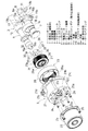
すなわち、この実施形態における可変動弁装置は、図1〜図4に示すようにシリンダヘッド1に図外のバルブガイドを介して摺動自在に設けられた一対の吸気弁2,2と、該各吸気弁2,2のバルブリフト量を可変制御する可変機構3と、該可変機構3の作動位置を制御する制御機構4と、該制御機構4を回転駆動するアクチュエータ5とを備えている。
That is, the variable valve operating apparatus in this embodiment includes a pair of
前記吸気弁2,2は、図2に示すように、シリンダヘッド1の上端部内に収容されたほぼ円筒状のボアの底部とバルブステム上端部のスプリングリテーナとの間に弾装されたバルブスプリング6,6のばね力によって閉方向に付勢されている。
As shown in FIG. 2, the
前記可変機構3は、機関前後方向に配置された内部中空状の駆動軸7と、各気筒毎に配置されて、前記駆動軸7の外周面に同軸上に回転自在に支持されたカムシャフト8と、前記駆動軸7の所定位置に固設された駆動カム9と、前記カムシャフト8の両端部に一体に設けられて、各吸気弁2,2の上端部に配設されたバルブリフター10、10に摺接して各吸気弁2,2を開作動させる一対の揺動カム11,11と、駆動カム9と揺動カム11,11との間に連係されて、駆動カム9の回転力を揺動カム11,11の揺動力(開弁力)として伝達する伝達機構とを備えている。
The
前記駆動軸7は、機関前後方向に沿って配置されて、両端部がシリンダヘッド1の上部に設けられた図外の軸受によって回転自在に軸支されていると共に、一端部に設けられた図外の従動スプロケットや該従動スプロケットに巻装されたタイミングチェーン等を介して機関のクランク軸から回転力が伝達されている。
The
前記各カムシャフト8は、駆動軸7の軸方向に沿ってほぼ円筒状に形成され、内部軸方向に前記駆動軸7の外周面に回転自在に支持される支軸孔が貫通形成されていると共に、中央位置に形成された円筒状のジャーナル部8aが前記軸受の上端部に一体的に設けられたカム軸受によって回転自在に軸支されている。
Each of the
前記駆動カム9は、ほぼ円盤状に形成されて、図2に示すように、その一側部に固定用の筒状部9aが一体に設けられており、この筒状部9aが駆動軸7の軸方向の所定位置で固定用ピン12を介して駆動軸7の外周に一体的に固定されていると共に、外周面が偏心円のカムプロフィールに形成されて、軸心Yが駆動軸7の軸心Xから径方向へ所定量だけオフセットしている。
The
前記各揺動カム11は、図1〜図3に示すように、同一形状のほぼ雨滴状を呈し、基端部側がカムシャフト8を介して前記駆動軸7の軸心Xを中心として揺動するようになっていると共に、揺動カム11の下面にはカム面11aがそれぞれ形成されている。
As shown in FIGS. 1 to 3, the
また、揺動カム11の前記カムノーズ部11b側には、後述するリンクロッド15の他端部15bと連結するピン18が挿通されるピン孔が両側面方向へ貫通形成されている。
Further, on the
前記伝達機構は、図1〜図3に示すように、駆動軸7の上方に配置されたロッカアーム13と、該ロッカアーム13の一端部13aと駆動カム9とを連係するリンクアーム14と、ロッカアーム13の他端部13bと一方の揺動カム11のカムノーズ部11bとを連係するリンクロッド15とを備えている。
As shown in FIGS. 1 to 3, the transmission mechanism includes a
前記ロッカアーム13は、中央の筒状基部の内部に支持孔13cが横方向から貫通形成され、この支持孔13cを介して後述する制御カム20に揺動自在に支持されている。また、前記一端部13aは、先端部の側部にピン16が一体に突設されている一方、他端部13bは、先端部の内部にリンクロッド15の一端部15aと連結するピン17が嵌入するピン孔が形成されている。
The
前記リンクアーム14は、比較的大径な円環部14aと、該円環部14aの外周面所定位置に突設された突出端14bとを備え、円環部14aの中央位置には、前記駆動カム9の外周面に回転自在に嵌合する嵌合孔14cが形成されていると共に、突出端14bには、前記ピン16が回転自在に挿通するピン孔が貫通形成されている。
The
前記リンクロッド15は、プレス成形によって一体に形成され、中央部が横断面ほぼコ字形状に形成されており、内側がコンパクト化を図るために、ほぼく字形状に折曲形成されていると共に、両端部15a,15bが前記ロッカアーム13の他端部13bと揺動カム11のカムノーズ部11b側にそれぞれ前記各ピン17,18を介して回転自在に連結されている。
The
前記制御機構4は、図1〜図3に示すように、駆動軸7の上方位置に配置された制御軸19と、該制御軸19の外周に一体に固定されてロッカアーム13の揺動支点となる制御カム20とを備えている。
As shown in FIGS. 1 to 3, the
前記制御軸19は、駆動軸7と並行に機関前後方向に配設されていると共に、前記カムシャフト8と共用の前記軸受の上端に有するブラケットに回転自在に支持されている。一方、前記制御カム20は、円筒状を呈し、軸心位置が肉厚部の分だけ制御軸19の軸心から所定分αだけ偏倚している。
The
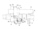
前記アクチュエータ5は、図1及び図4〜図7に示すように、シリンダヘッド1の後端部に固定されたハウジング21と、該ハウジング21の一端壁21aに取り付けられた回転駆動源である電動モータ22と、ハウジング21の内部に設けられて電動モータ21の回転駆動力を前記制御軸19に伝達する減速機構であるサイクロイド機構23とから構成されている。
As shown in FIGS. 1 and 4 to 7, the
前記ハウジング21は、熱伝導効率の高いアルミ合金材によって有蓋円筒状に形成されて、前記制御軸19の軸方向とほぼ同軸状に配置され、一端壁21aのほぼ中央に、ボールベアリング24を保持する保持孔21bが貫通形成されていると共に、外周の端部4個所にシリンダヘッド1の後端壁への固定用フランジ部21cが一体に形成されている。
The
また、ハウジング21の上端部に、角柱状のボス部21eが形成され、該ボス部21e内には、ハウジング21の内部へ潤滑油を導く潤滑油供給孔21dが形成されている一方、前記シリンダヘッド1の後端壁1aには、図4に示すようにハウジング21内を潤滑した潤滑油を排出するドレン孔1bが形成されている。そして、前記ハウジング21内には、前記潤滑油供給孔21dを介して機関の各摺動部を潤滑するエンジンオイルが導入されて、このエンジンオイルが内部を循環した後、前記ドレン孔1bから前記可変機構3などの動弁機構に排出されるようになっている。
Also, a prismatic boss portion 21e is formed at the upper end of the
また、前記ハウジング21と電動モータ22との間には、図4に示すように、両者21,22の内部の連通を遮断するシール部材38が介装されている。これにより、ハウジング21内の潤滑油が電動モータ22の内部に流入するのを効果的に阻止することができる。
Further, as shown in FIG. 4, a seal member 38 that interrupts communication between the
前記電動モータ22は、比例型のDCモータによって構成され、モータケーシングの先端部が前記一端壁21aに複数のボルト25によって軸方向から固定されていると共に、電動モータ22の出力軸である駆動シャフト22aが前記ボールベアリング24によって回転自在に支持されている。またこの電動モータ22は、機関の運転状態を検出する図外の電子コントローラ(ECU)からの制御信号によって駆動するようになっている。
The
この電子コントローラは、機関回転数を検出するクランク角センサや、吸入空気量を検出するエアーフローメータ、機関の水温を検出する水温センサ及び制御軸19の回転位置を検出するポテンショメータ等の各種のセンサからの検出信号をフィードバックして現在の機関運転状態を演算などにより検出して、前記電動モータ22に制御信号を出力している。
This electronic controller includes various sensors such as a crank angle sensor that detects the engine speed, an air flow meter that detects the intake air amount, a water temperature sensor that detects the engine water temperature, and a potentiometer that detects the rotational position of the
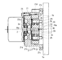
前記サイクロイド機構23は、電動モータ22の駆動シャフト22aに固定された偏心カム26と、中央に前記偏心カム26の外周面に摺動自在に嵌合する摺動孔27bを有する動力伝達部材である円環状の遊星ピニオンギア27と、前記ハウジング21の内部に複数のボルト29によって固定されて、内周側に前記遊星ピニオンギア27を公転及び自転させるように連係する非回転部材であるリングギア28と、前記遊星ピニオンギア27の偏心回動を同心回動に変換して回転を前記制御軸19に伝達する偏心吸収手段30とから構成されている。
The
前記偏心カム26は、図4及び図6〜図8に示すように、その中心Z1が駆動シャフト22aの軸心Zから所定量β偏心した位置で固定され、外周面がほぼ円形状に形成されている。
As shown in FIGS. 4 and 6 to 8, the
前記偏心カム26は、外形が偏心円形状に形成されて、中心から偏心した位置に前記駆動シャフト22aが貫通固定される固定孔26aが穿設されている。
The
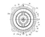
前記遊星ピニオンギア27は、前記偏心カム26の外周面と前記摺動孔27bとの間に設けられたボールベアリング31によって前記偏心カム26に相対回転自在に支持されていると共に、外周面全体にトロコイド形状の外歯27aが形成されている。
The
前記リングギア28は、内周面の内径が遊星ピニオンギア27の外径よりも僅かに大きく設定されていると共に、該内周面に前記遊星ピニオンギア27の外歯27aと噛合するトロコイド形状の内歯28aが形成されており、この内歯28aの歯数が外歯27aの歯数より一枚多く形成されている。これによって、電動モータ22の回転速度を減速させるようになっている。
The
前記偏心吸収手段30は、図1、図4、図7に示すように、前記偏心カム26の前端面側と制御軸19の一端部19aに設けられた円筒大径部32との間に配置され、内部に前記制御軸19の一端部19aが遊嵌状態に挿通される円環部33と、該円環部33の外周面から直径方向に沿って外方へ一体に突設された一対の2面幅状の突起部34、34と、前記遊星ピニオンギア27の一端面の直径方向の180°位置に突設されて、前記両突起部34、34に嵌合しつつ長手方向へ摺動案内されて遊星ピニオンギア27を、図7中、上下径方向への移動を許容する一対の二股状ガイド部35、35と、前記制御軸19の一端部19aに直径方向に貫通された固定用孔19bに挿通固定されたガイドピン36と、前記円環部33の両突起部34,34と直交する方向から貫通形成されて、前記ガイドピン36の両端部に摺動自在に挿入されて円環部33を、図7中、左右方向への移動を許容する摺動用孔37,37とから構成されている。
As shown in FIGS. 1, 4, and 7, the eccentric absorbing
したがって、前記遊星ピニオンギア27は、図7及び図8に示すように、偏心回転すると、円環部33の各突起部34,34に沿って各ガイド部35,35が径方向へ摺動すると共に、円環部33がガイドピン36を介してさらに90°の径方向へ摺動することによって、遊星ピニオンギア27の偏心回転を許容しつつ円環部33を介して制御軸19に回転力が伝達される。つまり、遊星ピニオンギア27の偏心回転に伴う公転及び自転による回転力は、ガイド部35,35から突起部34,34を介して円環部33に伝達され、さらに摺動用孔37,37を介してガイドピン36に伝達されるが、このとき円環部33は、ガイドピン36上を径方向へ自由に移動して遊星ピニオンギア27の偏心回転を吸収しつつ、ガイドピン36に遊星ピニオンギア27の自転力を伝達して制御軸19を回転させるようになっている。
Therefore, when the
また、前記ハウジング21内部には、前述のように、潤滑油供給孔21dから潤滑油が供給されて、各ボールベアリング24、31や内外歯27a、28a間に充填されるようになっている。
Inside the
以下、本実施形態の作用を説明すれば、まず、例えば、機関の低回転域では、この運転状態を検出したコントローラからの制御信号によって電動モータ22が回転駆動されて、偏心カム26が偏心回転すると、この偏心回転力によって遊星ピニオンギア27がリングギア28の内周側を噛合した内外歯27a、28aを介して逆方向へ偏心回転する。つまり、遊星ピニオンギア27は、駆動シャフト22aの回りを一方向へ自転しながら公転することになる。
The operation of the present embodiment will be described below. First, for example, in the low rotation range of the engine, the
これにより円環部33は、ガイド部35,35から各突起部34,34を介して減速された回転力を付与されながらガイドピン36を介して径方向へ自由に移動しながら偏心回転を吸収しつつ遊星ピニオンギア27の自転のみをガイドピン36を介して制御軸19に一方向の回転力を付与する。
As a result, the
したがって、制御軸19の一方向への回転に伴って制御カム20が、図9A、Bに示すように、軸心P2が制御軸19の軸心P1の回りを同一半径で回転して、肉厚部が駆動軸7から上方向に離間移動する。これにより、ロッカアーム13の他端部13bとリンクロッド15の枢支点は、駆動軸7に対して上方向へ移動し、このため、各揺動カム11は、リンクロッド15を介してカムノーズ部11b側が強制的に引き上げられる。
Accordingly, as the
よって、駆動カム9が回転してリンクアーム14を介してロッカアーム13の一端部13aを押し上げると、そのバルブリフト量がリンクロッド15を介して揺動カム11及びバルブリフター10に伝達されるが、そのリフト量は充分小さくなる。
Therefore, when the
したがって、かかる機関の低回転領域では、バルブリフト量L1が最も小さくなることにより、各吸気弁2の開時期が遅くなり、排気弁とのバルブオーバラップが小さくなる。このため、燃費の向上と機関の安定した回転が得られる。
Therefore, in the low rotation region of such an engine, the valve lift amount L1 is minimized, so that the opening timing of each
一方、機関が高回転領域に移行した場合は、これを検出したコントローラからの制御信号によって電動モータ22が逆回転して偏心カム26も同方向へ偏心回転すると、遊星ピニオンギア27もリングギア28の内周側を反対に偏心回転して、駆動シャフト22aの回りを他方向へ自転しながら公転することになる。
On the other hand, when the engine shifts to the high rotation region, when the
これにより円環部33は、ガイド部35,35から各突起部34,34を介して減速された回転力を付与されながらガイドピン36を介して径方向へ自由に移動しながら遊星ピニオンギア27の偏心回転を吸収しつつガイドピン36を介して制御軸19に他方向の回転力を付与する。
As a result, the
したがって、制御軸19は、制御カム20を図9に示す位置から時計方向へ回転させて、軸心P2が下方向へ移動する。このため、ロッカアーム13は、図10A、Bに示すように、今度は全体が駆動軸7方向に移動して他端部13bによって揺動カム11のカムノーズ部11bをリンクロッド15を介して下方へ押圧して該揺動カム11全体を所定量だけ反時計方向へ回動させる。
Therefore, the
したがって、揺動カム11のバルブリフター10の上面に対するカム面11aの当接位置が、カムノーズ部11b側(リフト部側)に移動する。このため、吸気弁2の開作動時に駆動カム9が回転してロッカアーム13の一端部13aをリンクアーム14を介して押し上げると、バルブリフター10に対するそのリフト量は十分に大きくなる。
Therefore, the contact position of the
よって、かかる高回転領域では、バルブリフト量L2が最大に大きくなり、各吸気弁2の開時期が早くなると共に、閉時期が遅くなる。この結果、吸気充填効率が向上し、十分な出力が確保できる。
Therefore, in such a high rotation region, the valve lift amount L2 is maximized, the opening timing of each
そして、この実施形態によれば、バルブスプリング6,6のばね力などに起因して発生して前記制御軸19に伝達された交番トルクは、ハウジング21内のサイクロイド機構23や偏心吸収手段30の各構成部材に伝達されるが、ハウジング21内に循環供給されている潤滑油(エンジンオイル)が、各内外歯27a、28a間に充填されているので、該各歯間27a、28aが十分に潤滑されることは勿論のこと、噛み合った内外歯27a、28a間などでの潤滑油による干渉ダンパー効果が得られると共に、偏心吸収手段30の各突起部34,34とガイド部35,35やガイドピン36と摺動用孔37,37との間の潤滑油による干渉ダンパー効果も得られる。
According to this embodiment, the alternating torque generated due to the spring force of the valve springs 6, 6 and transmitted to the
この結果、ハウジング21内での異音の発生を防止できると共に、交番トルクの電動モータ22に対する伝達を遮断することが可能になる。
As a result, it is possible to prevent the generation of abnormal noise in the
しかも、潤滑油は、ハウジング21内を循環するようになっていることから、該ハウジング21内の潤滑油の劣化を防止できるばかりか、サイクロイド機構23や偏心吸収手段30の前記各構成部材を効果的に冷却することができる。
In addition, since the lubricating oil circulates in the
また、電動モータで発生した高熱は、ハウジング21に伝達されて、ここで、潤滑油に吸熱されて外部に放出される。つまり、ハウジング21内を循環する潤滑油によって熱交換することにより、電動モータ21を効果的に冷却することが可能になる。この結果、該電動モータ21の耐久性の向上が図れる。
Further, high heat generated by the electric motor is transmitted to the
特に、ハウジング21自体が、熱伝導率の高いアルミ合金材によって構成されていることから、潤滑油による熱交換を効率良く行うことが可能になる。
In particular, since the
また、前述したように、制御軸19から伝達された交番トルクは、まず、ガイドピン36や円環部33及びガイド部35などの偏心吸収手段30を介して遊星ピニオンギア27に入力されるが、この遊星ピニオンギア27はリングギア28内で公転しながら自転するようになっている。すなわち、両ギアが同軸的に回転するのではなく、遊星ピニオンギア27がリングギア28の内周側を、いわば転がりながら偏心回転(公転)及び自転することから、リングギア28と噛合している部分での交番トルクの正負の回転方向での干渉が発生しない。
As described above, the alternating torque transmitted from the
また、偏心カム26は、遊星ピニオンギア27の摺動孔27a内に相対回転自在に収容されていることから、従来のようなボール螺子伝達手段の各ボールとボール溝との噛み合い部における交番トルクによる干渉が発生しない。
Further, since the
この結果、制御軸19に交番トルクが作用しても、偏心カム26に伝達されることがない。この結果、異音の発生を十分に抑制することが可能になると共に、電動モータ22の回転負荷の発生を防止することができる。
As a result, even if an alternating torque acts on the
前記遊星ピニオンギア27の外周面に外歯27aが形成されていると共に、前記リングギア28の内周面に、前記外歯27aに噛合する内歯28aが形成されていることから、内外歯27a、28aを用いることによって、リングギア28に対する遊星ピニオンギア27の回転性が確実になる。しかも、互いの内外歯27a、28aを介して遊星ピニオンギア27が、前述のように、転がるようになっているので、各歯27a、28a間にバックラッシが存在しても互いのガタ付きを最小限に抑えることが可能になる。
Since the
さらに、各内歯28aと各外歯27aとの見かけ上の噛み合い領域を多くすることができるので、たとえ、バックラッシに起因するガタ付きが生じたとしても、該噛み合い部を分散させることができ、これによって異音の発生を防止することができる。
Furthermore, since it is possible to increase the apparent meshing area between each
また、この実施形態では、偏心カム26と遊星ピニオンギア27との間に、ボールベアリング31を介装したことから、遊星ピニオンギア27と偏心カム26との間の摩擦抵抗の発生を抑制でき、常時円滑な回動が得られると共に、両者間でのガタ付きの発生も防止できる。
Further, in this embodiment, since the
また、前記遊星ピニオンギア27の外歯27aとリングギア28の内歯28aを、インボリュート曲線のトロコイド形状とすることも可能であり、このような形状にすると、歯面同士の干渉をさらに防止することが可能になる。
Further, the
さらに、この実施形態では、単にハウジング21内に設けられた偏心カム26や遊星ピニオンギア27及びリングギア28を用いた簡単な構造のサイクロイド機構を利用したため、装置全体の軽量化とコンパクト化が図れ、内燃機関への搭載性が良好になる。
Further, in this embodiment, since the cycloid mechanism having a simple structure using the
また、本発明は、前記実施形態の構成に限定されるものではなく、例えば、回転駆動源としては、電動モータ22の他に、油圧モータなどであってもよく、また動力伝達部材と非回転部材との間に、内外歯を設けずにそれぞれの内外周面を単純な円形状に形成することも可能であり、さらに動力伝達部材を非回転部材内を複数のピンを介して公転及び自転させることも可能である。
Further, the present invention is not limited to the configuration of the above-described embodiment. For example, the rotation drive source may be a hydraulic motor other than the
さらに、各ベアリングをボールベアリングに代えてプレーンベアリングとすることも可能であり、さらに可変機構としては、制御軸19を回転させることによってバルブタイミングを可変制御するものやバルブリフト量のみを可変制御するものにも適用することができる。
Furthermore, each bearing can be replaced with a plain bearing instead of a ball bearing. Further, as a variable mechanism, the valve timing is variably controlled by rotating the
また、偏心吸収手段30としては、前記実施形態に記載したもの以外に、オルダム継手や、複数の円形孔とそれに偏心可能に挿通される円柱突起によって構成することも可能である。 Moreover, as the eccentric absorption means 30, other than what was described in the said embodiment, it is also possible to comprise an Oldham coupling, a plurality of circular holes, and a cylindrical projection inserted through the circular holes.
また、前記ハウジング21は、熱伝達効率の良い材料であれば、前記アルミ合金材以外に、鉄系金属材などによって形成することも可能である。
The
さらに、本実施形態では、潤滑油としてエンジンオイルを用いたが、例えば内外歯27a、28a間に充填可能な粘度のものであれば種類は問わない。
Further, in the present embodiment, engine oil is used as the lubricating oil, but any type can be used as long as it has a viscosity that can be filled between the inner and
前記実施形態から把握される前記請求項に記載した発明以外の技術的思想について以下に説明する。
(1)前記ハウジングと電動モータとの間に、ハウジングの内部と電動モータの内部との間をシールするシール部材を設けたことを特徴とする請求項2または3に記載の内燃機関の可変動弁装置。
The technical ideas other than the invention described in the claims, as grasped from the embodiment, will be described below.
(1) The variable motion of the internal combustion engine according to
この発明によれば、シール部材によってハウジング内の潤滑油が電動モータへ流入するのを阻止することができる。
(2) 前記減速機構は、
前記回転駆動源の出力軸から回転力が入力されて、前記出力軸の軸心に対して偏心回転する外周円形状の偏心カムと、
内周に前記偏心カムが相対回転可能に収容される円形状の摺動孔を有し、前記偏心カムの回転に応じて偏心回転する動力伝達部材と、
ほぼ円形状の内周面に前記動力伝達部材の外周面が当接することによって前記動力伝達部材を自転しながら公転させる非回転部材と、
前記動力伝達部材の偏心回転を同心回転に変換して該回転力を前記制御軸に伝達する偏心吸収手段とから構成したことを特徴とする内燃機関の可変動弁装置。
(3)前記可変機構は、機関運転状態に応じて前記機関弁のバルブリフト量を可変制御することを特徴とする請求項1〜(2)のいずれかに記載の内燃機関の可変動弁装置。
(4)前記可変機構は、機関運転状態に応じて前記機関弁のリフト中心の位相を可変制御することを特徴とする請求項1〜(2)のいずれかに記載の内燃機関の可変動弁装置。
(5)前記可変機構は、機関運転状態に応じて前記機関弁のバルブリフトとリフト作動角とを可変制御することを特徴とする請求項1〜(2)のいずれかに記載の内燃機関の可変動弁装置。
According to the present invention, the lubricating oil in the housing can be prevented from flowing into the electric motor by the seal member.
(2) The deceleration mechanism is
A rotational force is input from the output shaft of the rotational drive source, and an outer circumferential circular eccentric cam that rotates eccentrically with respect to the axis of the output shaft;
A power transmission member having a circular slide hole in which the eccentric cam is accommodated in an inner periphery so as to be relatively rotatable, and which rotates eccentrically according to the rotation of the eccentric cam;
A non-rotating member that revolves while rotating the power transmission member by contacting the outer peripheral surface of the power transmission member to a substantially circular inner peripheral surface;
A variable valve operating apparatus for an internal combustion engine, comprising: an eccentric absorbing means for converting an eccentric rotation of the power transmission member into a concentric rotation and transmitting the rotational force to the control shaft.
(3) The variable valve operating apparatus for an internal combustion engine according to any one of (1) and (2), wherein the variable mechanism variably controls a valve lift amount of the engine valve according to an engine operating state. .
(4) The variable valve for an internal combustion engine according to any one of claims 1 to 2, wherein the variable mechanism variably controls a phase of a lift center of the engine valve in accordance with an engine operating state. apparatus.
(5) The internal combustion engine according to any one of claims 1 to 2, wherein the variable mechanism variably controls a valve lift and a lift operating angle of the engine valve in accordance with an engine operating state. Variable valve gear.
1…シリンダヘッド
1a…後端壁
1b…ドレン孔
2…吸気弁(機関弁)
3…可変機構
4…制御機構
5…アクチュエータ
6…バルブスプリング
21…ハウジング
22…電動モータ
23…サイクロイド機構
26…偏心カム
27…遊星ピニオンギア(動力伝達部材)
27b…摺動孔
27d…潤滑油供給孔
28…リングギア(非回転部材)
30…偏心吸収手段
DESCRIPTION OF SYMBOLS 1 ...
DESCRIPTION OF
27b ... Sliding hole 27d ... Lubricating
30: Eccentric absorption means
Claims (3)
前記電動モータから回転力が入力されると共に、回転中心に対して中心が偏心して設けられた偏心カムと、
中央に前記偏心カムを収容する摺動孔を有し、外周面全体にトロコイド形状の外歯が形成された遊星ピニオンギアと、
前記偏心カムと摺動孔の間に設けられたボールベアリングと、
内周に前記遊星ピニオンギアの外歯よりも歯数が多く、前記遊星ピニオンギアの外歯と噛み合うトロコイド形状の内歯が形成されたリングギアと、を備え、
前記電動モータの回転によって、前記リングギアの内部で前記遊星ピニオンギアが自転しながら公転することにより、バルブスプリングのばね力に抗して開弁する機関弁のリフト中心の位相を可変にしてバルブタイミングを制御し、
前記外歯と内歯との間及び前記ボールベアリングに潤滑油を循環供給することによって、前記外歯と内歯との間及び前記ボールベアリングに潤滑油を充填すると共に、前記遊星ピニオンギアとリングギア及びボールベアリングを冷却することを特徴とする内燃機関の可変動弁装置。 An electric motor that rotates according to engine operating conditions;
A rotational force is input from the electric motor, and an eccentric cam provided with an eccentric center with respect to the rotation center;
A planetary pinion gear having a sliding hole for accommodating the eccentric cam in the center and having trochoidal outer teeth formed on the entire outer peripheral surface;
A ball bearing provided between the eccentric cam and the sliding hole;
A ring gear having a trochoid-shaped inner tooth formed on the inner circumference, which has more teeth than the outer teeth of the planetary pinion gear and meshes with the outer teeth of the planetary pinion gear;
The rotation of the electric motor causes the planetary pinion gear to revolve inside the ring gear while rotating, thereby changing the phase of the lift center of the engine valve that opens against the spring force of the valve spring. Control the timing,
Lubricating oil is circulated and supplied between the outer teeth and the inner teeth and the ball bearing, so that the lubricating oil is filled between the outer teeth and the inner teeth and the ball bearing, and the planetary pinion gear and the ring are filled. A variable valve operating apparatus for an internal combustion engine, wherein a gear and a ball bearing are cooled.
前記電動モータから回転力が入力されると共に、回転中心に対して中心が偏心して設けられた偏心カムと、
中央に前記偏心カムを収容する摺動孔を有し、外周面全体にトロコイド形状の外歯が形成された遊星ピニオンギアと、
前記偏心カムと摺動孔の間に設けられたボールベアリングと、
内周に前記遊星ピニオンギアの外歯よりも歯数が多く、前記遊星ピニオンギアの外歯と噛み合うトロコイド形状の内歯が形成されたリングギアと、を備え、
前記電動モータの回転によって、前記リングギアの内部で前記遊星ピニオンギアが自転しながら公転することにより、バルブスプリングのばね力に抗して開弁する機関弁のリフト中心の位相を可変にしてバルブタイミングを制御し、
前記外歯と内歯の間に潤滑油を供給することによって、前記外歯と内歯の間に潤滑油を充填すると共に、前記外歯と内歯の間に供給された潤滑油を、前記電動モータで発生した熱が伝達される部材に供給し、その後、外部に排出することを特徴とする内燃機関の可変動弁装置。 An electric motor that rotates according to engine operating conditions;
A rotational force is input from the electric motor, and an eccentric cam provided with an eccentric center with respect to the rotation center;
A planetary pinion gear having a sliding hole for accommodating the eccentric cam in the center and having trochoidal outer teeth formed on the entire outer peripheral surface;
A ball bearing provided between the eccentric cam and the sliding hole;
A ring gear having a trochoid-shaped inner tooth formed on the inner circumference, which has more teeth than the outer teeth of the planetary pinion gear and meshes with the outer teeth of the planetary pinion gear;
The rotation of the electric motor causes the planetary pinion gear to revolve inside the ring gear while rotating, thereby changing the phase of the lift center of the engine valve that opens against the spring force of the valve spring. Control the timing,
By supplying lubricating oil between the external teeth and the internal teeth, the lubricating oil is filled between the external teeth and the internal teeth, and the lubricating oil supplied between the external teeth and the internal teeth is A variable valve operating apparatus for an internal combustion engine, characterized in that the heat generated by the electric motor is supplied to a member to which heat is transmitted and then discharged to the outside.
前記外歯と内歯の間及び電動モータで発生した熱が伝達される部材に供給された後の潤滑油を、シリンダヘッド内に排出したことを特徴とする内燃機関の可変動弁装置。 The variable valve operating apparatus for an internal combustion engine according to claim 2,
A variable valve operating apparatus for an internal combustion engine, wherein the lubricating oil after being supplied to a member to which heat generated by an electric motor is transmitted between the outer teeth and the inner teeth is discharged into a cylinder head.
Priority Applications (1)
| Application Number | Priority Date | Filing Date | Title |
|---|---|---|---|
| JP2008111991A JP4847980B2 (en) | 2008-04-23 | 2008-04-23 | Variable valve operating device for internal combustion engine |
Applications Claiming Priority (1)
| Application Number | Priority Date | Filing Date | Title |
|---|---|---|---|
| JP2008111991A JP4847980B2 (en) | 2008-04-23 | 2008-04-23 | Variable valve operating device for internal combustion engine |
Related Parent Applications (1)
| Application Number | Title | Priority Date | Filing Date |
|---|---|---|---|
| JP2003347779A Division JP4484485B2 (en) | 2003-10-07 | 2003-10-07 | Variable valve operating device for internal combustion engine |
Publications (3)
| Publication Number | Publication Date |
|---|---|
| JP2008223766A JP2008223766A (en) | 2008-09-25 |
| JP2008223766A5 JP2008223766A5 (en) | 2010-05-06 |
| JP4847980B2 true JP4847980B2 (en) | 2011-12-28 |
Family
ID=39842644
Family Applications (1)
| Application Number | Title | Priority Date | Filing Date |
|---|---|---|---|
| JP2008111991A Expired - Fee Related JP4847980B2 (en) | 2008-04-23 | 2008-04-23 | Variable valve operating device for internal combustion engine |
Country Status (1)
| Country | Link |
|---|---|
| JP (1) | JP4847980B2 (en) |
Families Citing this family (2)
| Publication number | Priority date | Publication date | Assignee | Title |
|---|---|---|---|---|
| JP6121207B2 (en) * | 2013-03-25 | 2017-04-26 | 本田技研工業株式会社 | Variable valve operating device for OHC type internal combustion engine |
| JP7006023B2 (en) * | 2017-08-30 | 2022-01-24 | 株式会社デンソー | Eccentric swing type speed reducer |
Family Cites Families (2)
| Publication number | Priority date | Publication date | Assignee | Title |
|---|---|---|---|---|
| JPH08270410A (en) * | 1995-03-31 | 1996-10-15 | Suzuki Motor Corp | Auxiliary drive device of internal combustion engine |
| JP3977538B2 (en) * | 1999-02-15 | 2007-09-19 | 株式会社日立製作所 | Variable valve operating device for internal combustion engine |
-
2008
- 2008-04-23 JP JP2008111991A patent/JP4847980B2/en not_active Expired - Fee Related
Also Published As
| Publication number | Publication date |
|---|---|
| JP2008223766A (en) | 2008-09-25 |
Similar Documents
| Publication | Publication Date | Title |
|---|---|---|
| JP4922121B2 (en) | Variable stroke engine | |
| JP2010024905A (en) | Actuator apparatus and variable valve gear for internal combustion engine adopting the actuator apparatus | |
| JP2010138736A (en) | Valve timing control device for internal combustion engine | |
| JP2010138735A (en) | Valve timing control device for internal combustion engine | |
| JP4996708B2 (en) | Variable valve operating device for internal combustion engine | |
| JP4847980B2 (en) | Variable valve operating device for internal combustion engine | |
| JP4484484B2 (en) | Variable valve operating device for internal combustion engine | |
| JP4225321B2 (en) | Variable valve mechanism | |
| JP2005194986A (en) | Valve operating characteristic variable device | |
| JP2012092721A (en) | Variable valve timing device | |
| JP4484485B2 (en) | Variable valve operating device for internal combustion engine | |
| JP4261838B2 (en) | Actuator device | |
| JP5189126B2 (en) | Internal combustion engine | |
| JP4219782B2 (en) | Variable valve operating device for internal combustion engine | |
| JP2016061234A (en) | Valve opening/closing timing control device | |
| JP2010270633A (en) | Actuator | |
| JP4847979B2 (en) | Variable valve operating device for internal combustion engine | |
| JP4847981B2 (en) | Variable valve operating device for internal combustion engine | |
| CN210889055U (en) | Electric phase regulator | |
| JP4278604B2 (en) | Variable valve actuator | |
| JP3797083B2 (en) | Variable valve operating device for internal combustion engine | |
| JP4516453B2 (en) | Valve operating device for internal combustion engine | |
| JP2009041507A (en) | Internal combustion engine | |
| JP4149774B2 (en) | Actuator device | |
| JP2004332549A (en) | Actuator for variable valve system |
Legal Events
| Date | Code | Title | Description |
|---|---|---|---|
| A521 | Written amendment |
Free format text: JAPANESE INTERMEDIATE CODE: A523 Effective date: 20090513 |
|
| A711 | Notification of change in applicant |
Free format text: JAPANESE INTERMEDIATE CODE: A712 Effective date: 20090922 |
|
| RD03 | Notification of appointment of power of attorney |
Free format text: JAPANESE INTERMEDIATE CODE: A7423 Effective date: 20090922 |
|
| A521 | Written amendment |
Free format text: JAPANESE INTERMEDIATE CODE: A523 Effective date: 20100324 |
|
| A131 | Notification of reasons for refusal |
Free format text: JAPANESE INTERMEDIATE CODE: A131 Effective date: 20110426 |
|
| A521 | Written amendment |
Free format text: JAPANESE INTERMEDIATE CODE: A523 Effective date: 20110602 |
|
| RD02 | Notification of acceptance of power of attorney |
Free format text: JAPANESE INTERMEDIATE CODE: A7422 Effective date: 20110602 |
|
| TRDD | Decision of grant or rejection written | ||
| A01 | Written decision to grant a patent or to grant a registration (utility model) |
Free format text: JAPANESE INTERMEDIATE CODE: A01 Effective date: 20111004 |
|
| A01 | Written decision to grant a patent or to grant a registration (utility model) |
Free format text: JAPANESE INTERMEDIATE CODE: A01 |
|
| A61 | First payment of annual fees (during grant procedure) |
Free format text: JAPANESE INTERMEDIATE CODE: A61 Effective date: 20111014 |
|
| FPAY | Renewal fee payment (event date is renewal date of database) |
Free format text: PAYMENT UNTIL: 20141021 Year of fee payment: 3 |
|
| R150 | Certificate of patent or registration of utility model |
Ref document number: 4847980 Country of ref document: JP Free format text: JAPANESE INTERMEDIATE CODE: R150 Free format text: JAPANESE INTERMEDIATE CODE: R150 |
|
| R250 | Receipt of annual fees |
Free format text: JAPANESE INTERMEDIATE CODE: R250 |
|
| R250 | Receipt of annual fees |
Free format text: JAPANESE INTERMEDIATE CODE: R250 |
|
| R250 | Receipt of annual fees |
Free format text: JAPANESE INTERMEDIATE CODE: R250 |
|
| R250 | Receipt of annual fees |
Free format text: JAPANESE INTERMEDIATE CODE: R250 |
|
| R250 | Receipt of annual fees |
Free format text: JAPANESE INTERMEDIATE CODE: R250 |
|
| R250 | Receipt of annual fees |
Free format text: JAPANESE INTERMEDIATE CODE: R250 |
|
| LAPS | Cancellation because of no payment of annual fees |