JP4847981B2 - Variable valve operating device for internal combustion engine - Google Patents
Variable valve operating device for internal combustion engine Download PDFInfo
- Publication number
- JP4847981B2 JP4847981B2 JP2008111992A JP2008111992A JP4847981B2 JP 4847981 B2 JP4847981 B2 JP 4847981B2 JP 2008111992 A JP2008111992 A JP 2008111992A JP 2008111992 A JP2008111992 A JP 2008111992A JP 4847981 B2 JP4847981 B2 JP 4847981B2
- Authority
- JP
- Japan
- Prior art keywords
- control shaft
- valve
- electric motor
- pinion gear
- planetary pinion
- Prior art date
- Legal status (The legal status is an assumption and is not a legal conclusion. Google has not performed a legal analysis and makes no representation as to the accuracy of the status listed.)
- Expired - Lifetime
Links
- 238000002485 combustion reaction Methods 0.000 title claims description 14
- 230000007246 mechanism Effects 0.000 claims description 71
- 230000002093 peripheral effect Effects 0.000 claims description 17
- 239000010687 lubricating oil Substances 0.000 claims description 12
- 230000009467 reduction Effects 0.000 claims description 8
- 230000005540 biological transmission Effects 0.000 description 26
- 239000000470 constituent Substances 0.000 description 4
- 230000002159 abnormal effect Effects 0.000 description 3
- 238000010521 absorption reaction Methods 0.000 description 3
- 230000000694 effects Effects 0.000 description 3
- 230000003111 delayed effect Effects 0.000 description 2
- 230000006872 improvement Effects 0.000 description 2
- 238000004519 manufacturing process Methods 0.000 description 2
- 238000005096 rolling process Methods 0.000 description 2
- XLYOFNOQVPJJNP-UHFFFAOYSA-N water Substances O XLYOFNOQVPJJNP-UHFFFAOYSA-N 0.000 description 2
- 230000009471 action Effects 0.000 description 1
- 238000006243 chemical reaction Methods 0.000 description 1
- 230000008878 coupling Effects 0.000 description 1
- 238000010168 coupling process Methods 0.000 description 1
- 238000005859 coupling reaction Methods 0.000 description 1
- 238000010586 diagram Methods 0.000 description 1
- 238000007599 discharging Methods 0.000 description 1
- 239000000446 fuel Substances 0.000 description 1
- 238000000465 moulding Methods 0.000 description 1
- 230000001105 regulatory effect Effects 0.000 description 1
Images


Classifications
-
- F—MECHANICAL ENGINEERING; LIGHTING; HEATING; WEAPONS; BLASTING
- F01—MACHINES OR ENGINES IN GENERAL; ENGINE PLANTS IN GENERAL; STEAM ENGINES
- F01L—CYCLICALLY OPERATING VALVES FOR MACHINES OR ENGINES
- F01L13/00—Modifications of valve-gear to facilitate reversing, braking, starting, changing compression ratio, or other specific operations
- F01L13/0015—Modifications of valve-gear to facilitate reversing, braking, starting, changing compression ratio, or other specific operations for optimising engine performances by modifying valve lift according to various working parameters, e.g. rotational speed, load, torque
- F01L13/0063—Modifications of valve-gear to facilitate reversing, braking, starting, changing compression ratio, or other specific operations for optimising engine performances by modifying valve lift according to various working parameters, e.g. rotational speed, load, torque by modification of cam contact point by displacing an intermediate lever or wedge-shaped intermediate element, e.g. Tourtelot
- F01L2013/0073—Modifications of valve-gear to facilitate reversing, braking, starting, changing compression ratio, or other specific operations for optimising engine performances by modifying valve lift according to various working parameters, e.g. rotational speed, load, torque by modification of cam contact point by displacing an intermediate lever or wedge-shaped intermediate element, e.g. Tourtelot with an oscillating cam acting on the valve of the "Delphi" type
Description
本発明は、機関弁である吸気弁や排気弁の作動特性であるバルブタイミングなどを機関運転状態に応じて可変にする可変機構を備えた内燃機関の可変動弁装置に関し、具体的には前記可変機構を駆動させるアクチュエータの改良に関する。 The present invention relates to a variable valve operating apparatus for an internal combustion engine provided with a variable mechanism that varies a valve timing, which is an operation characteristic of an intake valve or an exhaust valve, which is an engine valve, according to an engine operating state. The present invention relates to an improvement of an actuator that drives a variable mechanism.
この種の従来の内燃機関の可変動弁装置としては、本出願人が先に出願した以下の特許文献1に記載されたものがある。 As this type of conventional variable valve operating system for an internal combustion engine, there is one described in the following Patent Document 1 previously filed by the present applicant.
概略を説明すれば、この可変動弁装置は、吸気弁側に適用されたもので、クランク軸の回転に同期して回転する駆動軸の外周に、軸心が駆動軸の軸心から偏心した駆動カムが設けられていると共に、駆動カムの回転力が多節リンク状の伝達機構を介して伝達されて、吸気弁の上端部に有するバルブリフターの上面をカム面が摺接して吸気弁をバルブスプリングのばね力に抗して開作動させる揺動カムを有している。 Briefly, this variable valve operating device is applied to the intake valve side, and the shaft center is eccentric from the shaft center of the drive shaft on the outer periphery of the drive shaft rotating in synchronization with the rotation of the crankshaft. A drive cam is provided, and the rotational force of the drive cam is transmitted through a multi-link transmission mechanism, and the cam surface slides on the upper surface of the valve lifter at the upper end of the intake valve to control the intake valve. It has a swing cam that opens against the spring force of the valve spring.
前記伝達機構は、揺動カムの上方に配置されて制御軸に揺動自在に支持されたロッカアームと、円環状の一端部が駆動カムの外周面に嵌合しかつ他端部がロッカアームの一端部に回転自在に連結されたリンクアームと、一端部がロッカアームの他端部に回転自在に連結され、他端部が前記揺動カムのカムノーズ部に回転自在に連結されたリンクロッドとから構成されている。 The transmission mechanism includes a rocker arm that is disposed above the swing cam and is swingably supported by the control shaft, an annular one end is fitted to the outer peripheral surface of the drive cam, and the other end is one end of the rocker arm. A link arm that is rotatably connected to the rocker, and a link rod that has one end rotatably connected to the other end of the rocker arm and the other end rotatably connected to the cam nose of the swing cam. Has been.
また、前記制御軸は、シリンダヘッドの上端部に設けられた軸受によって回転自在に支持されており、その外周面には、軸心が制御軸の軸心から所定量だけ偏心した制御カムが固定されている。 The control shaft is rotatably supported by a bearing provided at the upper end of the cylinder head, and a control cam whose shaft center is eccentric from the control shaft axis by a predetermined amount is fixed to the outer peripheral surface thereof. Has been.
そして、アクチュエータである電動モータや該電動モータの回転を減速させる減速機構であるボール螺子伝達手段によって前記制御軸を回転制御し、さらにこの制御軸を介して制御カムの回動位置を変化させることによって、ロッカアームの揺動支点を変化させて揺動カムのカム面のバルブリフター上面に対する転接位置を変化させることにより、吸気弁のバルブリフト量を機関運転状態に応じて可変制御するようになっている。
ところで、一般に内燃機関は、吸気弁や排気弁の開閉作動時において、バルブスプリングの大きなばね反力に起因して、いわゆる正負の交番トルクが発生していることは周知の通りである。 By the way, as is well known, in general, an internal combustion engine generates a so-called positive and negative alternating torque due to a large spring reaction force of a valve spring when an intake valve or an exhaust valve is opened or closed.
この交番トルクは、前記従来の可変機構を備えたものにあっては、揺動カムからリンクアームやロッカアームなどの伝達機構を介して制御軸に伝達されており、該制御軸には、図11の波形特性図に示すような大きなトルク変動が発生している。 The alternating torque is transmitted from the swing cam to the control shaft via a transmission mechanism such as a link arm or a rocker arm in the case of the conventional variable mechanism. A large torque fluctuation as shown in the waveform characteristic diagram of FIG.
さらに、この制御軸に伝達された交番トルクは、前記ボール螺子伝達手段である減速機構に伝達されてしまう。このため、該ボール螺子伝達手段では、各ボールとボール軸外周の螺旋状ボール溝やボールナットのボール溝との噛み合い部などの伝達経路で交番トルクによる各部の干渉による激しい異音が発生するおそれがある。 Furthermore, the alternating torque transmitted to the control shaft is transmitted to the speed reduction mechanism which is the ball screw transmission means. For this reason, in the ball screw transmission means, there is a risk that severe abnormal noise is generated due to the interference of each part due to the alternating torque in the transmission path such as the meshing part of each ball with the spiral ball groove on the outer periphery of the ball shaft and the ball groove of the ball nut. There is.
本発明は、前記従来の可変動弁装置の技術的課題に鑑みて案出されたもので、請求項1に記載の発明は、機関運転状態に応じて回転する電動モータと、前記電動モータの回転を減速して、バルブスプリングのばね力に抗して開弁する機関弁のリフト中心の位相を可変にしてバルブタイミングを制御する制御軸に回転力を伝達する減速機構と、前記電動モータと制御軸との間に設けられ、該制御軸に回転力を伝達しかつ該制御軸の軸心に対して径方向へ移動可能な継手機構と、を備え、前記減速機構に供給された潤滑油が、常時前記減速機構の内部を循環しながら前記継手機構に供給されると共に、該継手機構からシリンダヘッド側に排出されることを特徴としている。 The present invention has been devised in view of the technical problem of the conventional variable valve gear, and the invention according to claim 1 is directed to an electric motor that rotates according to an engine operating state, and the electric motor. A speed reduction mechanism that transmits the rotational force to a control shaft that controls the valve timing by varying the phase of the lift center of the engine valve that decelerates rotation and opens the valve against the spring force of the valve spring; and the electric motor; And a coupling mechanism that is provided between the control shaft and that transmits a rotational force to the control shaft and that is movable in a radial direction with respect to the axis of the control shaft. Is supplied to the joint mechanism while constantly circulating inside the speed reduction mechanism, and is discharged from the joint mechanism to the cylinder head side.
この発明によれば、バルブスプリングのばね力などに起因して制御軸に伝達された交番トルクによる放射方向の振動は、継手機構に伝達されるが、この継手機構の径方向の自由な移動性によって、前記放射方向の振動を効果的に吸収することができる。 According to the present invention, the radial vibration due to the alternating torque transmitted to the control shaft due to the spring force of the valve spring, etc. is transmitted to the joint mechanism, but the radial mobility of the joint mechanism is free. Thus, the vibration in the radial direction can be effectively absorbed.
この結果、電動モータに対する振動伝達が確実に阻止されることから、該電動モータの駆動負荷が低減されて、該電動モータの円滑な回転駆動力が得られる。 As a result, since vibration transmission to the electric motor is reliably prevented, the driving load of the electric motor is reduced, and a smooth rotational driving force of the electric motor can be obtained.
請求項2に記載の発明にあっては、とりわけ、電動モータと制御軸の間に、該制御軸に回転力を伝達しかつ該制御軸の軸心に対して径方向へ移動可能な継手機構を設け、潤滑油を、常時前記ボールベアリングや内外歯間及び前記継手機構を循環させながら供給することを特徴としている。
In the invention described in
この発明によれば、前述のように、制御軸に伝達された交番トルクによる振動を吸収できることに加えて、遊星ピニオンギアやリングギアなどの動力伝達部材の偏心回転を継手機構によって効果的に吸収して同心回転を制御軸に付与することができる。 According to the present invention, as described above, in addition to being able to absorb the vibration due to the alternating torque transmitted to the control shaft, the joint mechanism effectively absorbs the eccentric rotation of the power transmission member such as the planetary pinion gear and the ring gear. Thus, concentric rotation can be applied to the control shaft.
以下、本発明に係る内燃機関の可変動弁装置の実施形態を図面に基づいて詳述する。 Embodiments of a variable valve operating apparatus for an internal combustion engine according to the present invention will be described below in detail with reference to the drawings.
この実施形態では、可変動弁装置を、従来と同じく、吸気弁側に適用したものであって、1気筒当たり2つの吸気弁を備え、かつ吸気弁のバルリフト量とリフト作動角を機関運転状態に応じて可変にするようになっている。 In this embodiment, the variable valve device is applied to the intake valve side as in the prior art, and includes two intake valves per cylinder, and the valve lift amount and lift operating angle of the intake valve are determined in the engine operating state. It is designed to be variable according to.
すなわち、この実施形態における可変動弁装置は、図1〜図4に示すようにシリンダヘッド1に図外のバルブガイドを介して摺動自在に設けられた一対の吸気弁2,2と、該各吸気弁2,2のバルブリフト量を可変制御する可変機構3と、該可変機構3の作動位置を制御する制御機構4と、該制御機構4を回転駆動するアクチュエータ5とを備えている。
That is, the variable valve operating apparatus in this embodiment includes a pair of
前記吸気弁2,2は、図2に示すように、シリンダヘッド1の上端部内に収容されたほぼ円筒状のボアの底部とバルブステム上端部のスプリングリテーナとの間に弾装されたバルブスプリング6,6のばね力によって閉方向に付勢されている。
As shown in FIG. 2, the
前記可変機構3は、機関前後方向に配置された内部中空状の駆動軸7と、各気筒毎に配置されて、前記駆動軸7の外周面に同軸上に回転自在に支持されたカムシャフト8と、前記駆動軸7の所定位置に固設された駆動カム9と、前記カムシャフト8の両端部に一体に設けられて、各吸気弁2,2の上端部に配設されたバルブリフター10、10に摺接して各吸気弁2,2を開作動させる一対の揺動カム11,11と、駆動カム9と揺動カム11,11との間に連係されて、駆動カム9の回転力を揺動カム11,11の揺動力(開弁力)として伝達する伝達機構とを備えている。
The
前記駆動軸7は、機関前後方向に沿って配置されて、両端部がシリンダヘッド1の上部に設けられた図外の軸受によって回転自在に軸支されていると共に、一端部に設けられた図外の従動スプロケットや該従動スプロケットに巻装されたタイミングチェーン等を介して機関のクランク軸から回転力が伝達されている。
The
前記各カムシャフト8は、駆動軸7の軸方向に沿ってほぼ円筒状に形成され、内部軸方向に前記駆動軸7の外周面に回転自在に支持される支軸孔が貫通形成されていると共に、中央位置に形成された円筒状のジャーナル部8aが前記軸受の上端部に一体的に設けられたカム軸受によって回転自在に軸支されている。
Each of the
前記駆動カム9は、ほぼ円盤状に形成されて、図2に示すように、その一側部に固定用の筒状部9aが一体に設けられており、この筒状部9aが駆動軸7の軸方向の所定位置で固定用ピン12を介して駆動軸7の外周に一体的に固定されていると共に、外周面が偏心円のカムプロフィールに形成されて、軸心Yが駆動軸7の軸心Xから径方向へ所定量だけオフセットしている。
The
前記各揺動カム11は、図1〜図3に示すように、同一形状のほぼ雨滴状を呈し、基端部側がカムシャフト8を介して前記駆動軸7の軸心Xを中心として揺動するようになっていると共に、揺動カム11の下面にはカム面11aがそれぞれ形成されている。
As shown in FIGS. 1 to 3, the
また、揺動カム11の前記カムノーズ部11b側には、後述するリンクロッド15の他端部15bと連結するピン18が挿通されるピン孔が両側面方向へ貫通形成されている。
Further, on the
前記伝達機構は、図1〜図3に示すように、駆動軸7の上方に配置されたロッカアーム13と、該ロッカアーム13の一端部13aと駆動カム9とを連係するリンクアーム14と、ロッカアーム13の他端部13bと一方の揺動カム11のカムノーズ部11bとを連係するリンクロッド15とを備えている。
As shown in FIGS. 1 to 3, the transmission mechanism includes a
前記ロッカアーム13は、中央の筒状基部の内部に支持孔13cが横方向から貫通形成され、この支持孔13cを介して後述する制御カム20に揺動自在に支持されている。また、前記一端部13aは、先端部の側部にピン16が一体に突設されている一方、他端部13bは、先端部の内部にリンクロッド15の一端部15aと連結するピン17が嵌入するピン孔が形成されている。
The
前記リンクアーム14は、比較的大径な中間部14aと、該中間部14aの外周面所定位置に突設された突出端14bとを備え、中間部14aの中央位置には、前記駆動カム9の外周面に回転自在に嵌合する嵌合孔14cが形成されていると共に、突出端14bには、前記ピン16が回転自在に挿通するピン孔が貫通形成されている。
The
前記リンクロッド15は、プレス成形によって一体に形成され、中央部が横断面ほぼコ字形状に形成されており、内側がコンパクト化を図るために、ほぼく字形状に折曲形成されていると共に、両端部15a,15bが前記ロッカアーム13の他端部13bと揺動カム11のカムノーズ部11b側にそれぞれ前記各ピン17,18を介して回転自在に連結されている。
The
前記制御機構4は、図1〜図3に示すように、駆動軸7の上方位置に配置された制御軸19と、該制御軸19の外周に一体に固定されてロッカアーム13の揺動支点となる制御カム20とを備えている。
As shown in FIGS. 1 to 3, the
前記制御軸19は、駆動軸7と並行に機関前後方向に配設されていると共に、前記カムシャフト8と共用の前記軸受の上端に有するブラケットに回転自在に支持されている。一方、前記制御カム20は、円筒状を呈し、軸心位置が肉厚部の分だけ制御軸19の軸心から所定分αだけ偏倚している。
The
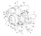
前記アクチュエータ5は、図1及び図4〜図7に示すように、シリンダヘッド1の後端部に固定されたハウジング21と、該ハウジング21の一端壁21aに固定された回転駆動源である電動モータ22と、ハウジング21の内部に設けられて電動モータ21の回転駆動力を前記制御軸19に伝達する減速機構であるサイクロイド機構23とから構成されている。
As shown in FIGS. 1 and 4 to 7, the
前記ハウジング21は、有蓋円筒状に形成されて、前記制御軸19の軸方向とほぼ同軸状に配置され、一端壁21aのほぼ中央に、電動モータ22の出力軸である駆動シャフト22aを回転支持するボールベアリング24を支持する支持孔21bが貫通形成されていると共に、外周の端部4個所にシリンダヘッド1の後端壁への固定用ボス部21cが一体に形成されている。また、上端部には内部へ潤滑油を導く潤滑油供給孔21dが形成されている。なお、前記シリンダヘッド1の後端壁1aには、ハウジング21内を潤滑した潤滑油を排出するドレン孔1bが形成されている。
The
前記電動モータ22は、比例型のDCモータによって構成され、モータケーシングの先端部が前記一端壁21aに複数のボルト25によって軸方向から固定されていると共に、機関の運転状態を検出する図外の電子コントローラ(ECU)からの制御信号によって駆動するようになっている。
The
この電子コントローラは、機関回転数を検出するクランク角センサや、吸入空気量を検出するエアーフローメータ、機関の水温を検出する水温センサ及び制御軸19の回転位置を検出するポテンショメータ等の各種のセンサからの検出信号をフィードバックして現在の機関運転状態を演算などにより検出して、前記電動モータ22に制御信号を出力している。
This electronic controller includes various sensors such as a crank angle sensor that detects the engine speed, an air flow meter that detects the intake air amount, a water temperature sensor that detects the engine water temperature, and a potentiometer that detects the rotational position of the
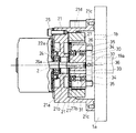
前記サイクロイド機構23は、電動モータ22の駆動シャフト22aに固定された偏心カム26と、中央に前記偏心カム26の外周面に摺動自在に嵌合する摺動孔27bを有する動力伝達部材である円環状の遊星ピニオンギア27と、前記ハウジング21の内部に複数のボルト29によって固定されて、内周側に前記遊星ピニオンギア27を公転及び自転させるように連係する非回転部材であるリングギア28と、前記遊星ピニオンギア27の偏心回動を同心回動に変換して回転を前記制御軸19に伝達する偏心吸収手段30とから構成されている。
The
前記偏心カム26は、図4及び図6〜図8に示すように、その中心Z1が駆動シャフト22aの軸心Zから所定量β偏心した位置で固定され、外周面がほぼ円形状に形成されている。
As shown in FIGS. 4 and 6 to 8, the
前記偏心カム26は、外形が偏心円形状に形成されて、中心から偏心した位置に前記駆動シャフト22aが貫通固定される固定孔26aが穿設されている。
The
前記遊星ピニオンギア27は、前記偏心カム26の外周面と前記摺動孔27bとの間に設けられたボールベアリング31によって前記偏心カム26に相対回転自在に支持されていると共に、外周面全体に外歯27aが形成されている。
The
前記リングギア28は、内周面の内径が遊星ピニオンギア27の外径よりも僅かに大きく設定されていると共に、該内周面に前記遊星ピニオンギア27の外歯27aと噛合する内歯28aが形成されており、この内歯28aの歯数が外歯27aの歯数より一枚多く形成されている。これによって、電動モータ22の回転速度を減速させるようになっている。
The
また、前記制御軸19と遊星ピニオンギア27との間には、該遊星ピニオンギア27の偏心回転を許容しながら、該偏心回転を同心回転に変換して、この回転力を前記制御軸19に伝達する継手機構30が設けられている。
Further, between the
前記継手機構30は、図1、図4、図7に示すように、前記偏心カム26の前端面側に配置され、中央の大径孔33a内に制御軸19の一端部19aが遊嵌状態に挿通された間に配置されたほぼ円環状の中間部33と、該中間部33の外周面から直径方向に沿って外方へ一体に突設された一対の2面幅状の突起部34、34と、前記遊星ピニオンギア27の一端面の直径方向の180°位置に突設されて、前記両突起部34、34に嵌合しつつ長手方向へ摺動案内されて遊星ピニオンギア27を図7中、上下径方向への移動を許容する一対の二股状ガイド部35、35と、前記制御軸19の一端部19aに直径方向に貫通された固定用孔19bに挿通固定されたガイドピン36と、前記中間部33の両突起部34,34と直交する方向から貫通形成されて、前記ガイドピン36の両端部に摺動自在に挿入されて中間部33を、図7中、左右方向への移動を許容する摺動用孔37,37とから構成されている。そして、前記両突起部34,34と両ガイド部35、35によって第1移動許容部が構成されていると共に、ガイドピン36と摺動用孔37、37によって第2移動許容部が構成されている。なお、制御軸19の一端部19a側に、中間部33の一端部19a側への移動を規制する円筒状の規制部32が固定されている。
As shown in FIGS. 1, 4 and 7, the
したがって、前記遊星ピニオンギア27は、図7及び図8に示すように、偏心回転すると、円環部33の各突起部34,34に沿って各ガイド部35,35が径方向へ摺動すると共に、円環部33がガイドピン36を介してさらに90°の径方向へ摺動することによって、遊星ピニオンギア27の偏心回転を許容しつつ円環部33を介して制御軸19に回転力が伝達される。つまり、遊星ピニオンギア27の偏心回転に伴う公転及び自転による回転力は、ガイド部35,35から突起部34,34を介して円環部33に伝達され、さらに摺動用孔37,37を介してガイドピン36に伝達されるが、このとき円環部33は、ガイドピン36上を径方向へ自由に移動して遊星ピニオンギア27の偏心回転を吸収しつつ、ガイドピン36に遊星ピニオンギア27の自転力を伝達して制御軸19を回転させるようになっている。
Therefore, when the
また、前記ハウジング21内部には、前述のように、潤滑油供給孔21dから潤滑油が供給されて、内部を循環しながら各ボールベアリング24、31や内外歯27a、28a間を潤滑し、さらにドレン孔1bから可変機構3などの動弁機構に排出されるようになっている。
Further, as described above, the lubricating oil is supplied into the
以下、本実施形態の作用を説明すれば、まず、例えば、機関の低回転域では、この運転状態を検出したコントローラからの制御信号によって電動モータ22が回転駆動されて、偏心カム26が偏心回転すると、この偏心回転力によって遊星ピニオンギア27がリングギア28の内周側を噛合した内外歯27a、28aを介して逆方向へ偏心回転する。つまり、遊星ピニオンギア27は、駆動シャフト22aの回りを一方向へ自転しながら公転することになる。
The operation of the present embodiment will be described below. First, for example, in the low rotation range of the engine, the
これにより中間部33は、ガイド部35,35から各突起部34,34を介して減速された回転力を付与されながらガイドピン36を介して径方向へ自由に移動しながら偏心回転を吸収しつつ遊星ピニオンギア27の自転のみをガイドピン36を介して制御軸19に一方向の回転力を付与する。
As a result, the
したがって、制御軸19の一方向への回転に伴って制御カム20が、図9A、Bに示すように、軸心P2が制御軸19の軸心P1の回りを同一半径で回転して、肉厚部が駆動軸7から上方向に離間移動する。これにより、ロッカアーム13の他端部13bとリンクロッド15の枢支点は、駆動軸7に対して上方向へ移動し、このため、各揺動カム11は、リンクロッド15を介してカムノーズ部11b側が強制的に引き上げられる。
Accordingly, as the
よって、駆動カム9が回転してリンクアーム14を介してロッカアーム13の一端部13aを押し上げると、そのバルブリフト量がリンクロッド15を介して揺動カム11及びバルブリフター10に伝達されるが、そのリフト量は充分小さくなる。
Therefore, when the
したがって、かかる機関の低回転領域では、バルブリフト量L1が最も小さくなることにより、各吸気弁2の開時期が遅くなり、排気弁とのバルブオーバラップが小さくなる。このため、燃費の向上と機関の安定した回転が得られる。
Therefore, in the low rotation region of such an engine, the valve lift amount L1 is minimized, so that the opening timing of each
一方、機関が高回転領域に移行した場合は、これを検出したコントローラからの制御信号によって電動モータ22が逆回転して偏心カム26も同方向へ偏心回転すると、遊星ピニオンギア27もリングギア28の内周側を反対に偏心回転して、駆動シャフト22aの回りを他方向へ公転しながら自転することになる。
On the other hand, when the engine shifts to the high rotation region, when the
これにより中間部33は、ガイド部35,35から各突起部34,34を介して減速された回転力を付与されながら、径方向へ自由に移動しながら偏心回転を吸収しつつガイドピン36を介して制御軸19に他方向の回転力を付与する。
As a result, the
したがって、制御軸19は、制御カム20を図9に示す位置から時計方向へ回転させて、軸心P2が下方向へ移動する。このため、ロッカアーム13は、図10A、Bに示すように、今度は全体が駆動軸7方向に移動して他端部13bによって揺動カム11のカムノーズ部11bをリンクロッド15を介して下方へ押圧して該揺動カム11全体を所定量だけ反時計方向へ回動させる。
Therefore, the
したがって、揺動カム11のバルブリフター10の上面に対するカム面11aの当接位置が、カムノーズ部11b側(リフト部側)に移動する。このため、吸気弁2の開作動時に駆動カム9が回転してロッカアーム13の一端部13aをリンクアーム14を介して押し上げると、バルブリフター10に対するそのリフト量は十分に大きくなる。
Therefore, the contact position of the
よって、かかる高回転領域では、バルブリフト量L2が最大に大きくなり、各吸気弁2の開時期が早くなると共に、閉時期が遅くなる。この結果、吸気充填効率が向上し、十分な出力が確保できる。
Therefore, in such a high rotation region, the valve lift amount L2 is maximized, the opening timing of each
そして、この実施形態によれば、バルブスプリングのばね力などに起因して制御軸19に伝達された交番トルクによる放射方向の振動は、継手機構30のガイドピン36を介して中間部33に伝達されるが、この中間部33は前記ガイドピン36と摺動用孔37,37を介して径方向へ自由に移動するため、これによって、前記放射方向の振動を効果的に吸収することができる。
According to this embodiment, the radial vibration due to the alternating torque transmitted to the
この結果、遊星ピニオンギア27などのサイクロイド機構23や電動モータ22に対する振動伝達が確実に阻止されることから、該電動モータ22の回転駆動負荷が低減されて、該電動モータ22の常時円滑な回転駆動力が得られる。
As a result, vibration transmission to the
また、継手機構30は、構造が簡単であるから、前述のように、遊星ピニオンギア27の偏心回転を効率よく同心回転に変換することができることは勿論のこと、各構成部材の製造誤差を可及的に小さくすることが可能になる。また、継手機構30は、小型化しているため、制御軸19と遊星ピニオンギア27との間への組付性も良好になる。
Further, since the
さらに、継手機構30を、前記制御軸19と遊星ピニオンギア27に組み付けるに際し、先に中間部33を摺動用孔37,37内にガイドピン26に連係して、制御軸19に組み付け、その後、各突起部34,34を遊星ピニオンギア27のガイド部35,35に凹凸嵌合させるようにしたため、組み付け作業の段取りが良好になり、該組付作業が容易になる。
Further, when the
しかも、継手機構30の一部を、円柱状のガイドピン36や円形状の摺動用孔37,37によって形成したため、これらの加工精度を高くすることが可能になり、この結果、前記両者間のガタ付きの発生を抑制できる。
In addition, since a part of the
また、この実施形態によれば、前記交番トルクは、継手機構30によって効果的に吸収されて、サイクロイド機構23には伝達されることはないが、たとえ僅かに遊星ピニオンギア27に入力されたとしても、遊星ピニオンギア27がリングギア28の内周側を、いわば転がりながら偏心回転(公転)及び自転することから、リングギア28と噛合している部分での交番トルクの正負の回転方向での干渉が防止される。したがって、異音の発生を抑制することが可能になる。
Further, according to this embodiment, the alternating torque is effectively absorbed by the
また、偏心カム26は、遊星ピニオンギア27の摺動孔27a内に相対回転自在に収容されていることから、従来のようなボール螺子伝達手段の各ボールとボール溝との噛み合い部における交番トルクによる干渉が発生しない。
Further, since the
また、ハウジング21内の潤滑油によって遊星ピニオンギア27とリングギア28の各内外歯27a、28a間には、常時潤滑油が供給されていることから、該各歯間27a、28aが十分に潤滑されることは勿論のこと、噛み合った内外歯27a、28a間での干渉ダンパー効果が得られる。
Further, since the lubricating oil in the
さらに、この実施形態では、単にハウジング21内に設けられた偏心カム26や遊星ピニオンギア27及びリングギア28を用いた簡単な構造のサイクロイド機構を利用したため、装置全体の軽量化とコンパクト化が図れ、内燃機関への搭載性が良好になる。
Further, in this embodiment, since the cycloid mechanism having a simple structure using the
また、本発明は、前記実施形態の構成に限定されるものではなく、例えば、第1移動許容部における2面幅状の突起部34,34やガイド部35,35を、それぞれの円周方向の90°位置に3つ以上形成することも可能であり、1つでも構わない。
In addition, the present invention is not limited to the configuration of the above-described embodiment. For example, the
また、回転駆動源としては、電動モータ22の他に、油圧モータなどであってもよく、また動力伝達部材と非回転部材との間に、内外歯27a、27aを設けずにそれぞれの内外周面を単純な円形状に形成することも可能であり、さらに動力伝達部材を非回転部材内を複数のピンを介して公転及び自転させることも可能である。
In addition to the
さらに、各ベアリングをボールベアリングに代えてプレーンベアリングとすることも可能であり、さらに可変機構としては、制御軸19を回転させることによってバルブタイミングを可変制御するものやバルブリフト量のみを可変制御するものにも適用することができる。
Furthermore, each bearing can be replaced with a plain bearing instead of a ball bearing. Further, as a variable mechanism, the valve timing is variably controlled by rotating the
また、継手機構30としては、前記実施形態に記載したもの以外に、オルダム継手や、複数の円形孔とそれに偏心可能に挿通される円柱突起などによって構成することも可能である。
Further, the
前記実施形態から把握される前記請求項に記載した発明以外の技術的思想について以下に説明する。
(1)前記継手機構に潤滑油を供給したことを特徴とする請求項1〜3のいずれかに記載の内燃機関の可変動弁装置。
The technical ideas other than the invention described in the claims, as grasped from the embodiment, will be described below.
(1) The variable valve operating apparatus for an internal combustion engine according to any one of claims 1 to 3, wherein lubricating oil is supplied to the joint mechanism.
この発明によれば、継手機構の各構成部材間に潤滑油が入り込んで、該各構成部材間の潤滑性を確保することは勿論のこと、各構成部材間での干渉ダンパー効果を発揮させることが可能になる。これによって、各構成部材間でのガタつきに伴う異音の発生を防止することができる。
(2)第1移動許容部あるいは第2移動許容部を、前記制御軸あるいは動力伝達部材に対して着脱可能に連係させると共に、他方側の移動許容部を、他方側の前記制御軸あるいは動力伝達部材に対して着脱不能に連係させたことを特徴とする請求項3または(1)に記載の内燃機関の可変動弁装置。
According to the present invention, lubricating oil enters between the constituent members of the joint mechanism to ensure the lubricity between the constituent members, and to exhibit the interference damper effect between the constituent members. Is possible. As a result, it is possible to prevent the generation of abnormal noise due to rattling between the constituent members.
(2) The first movement allowance part or the second movement allowance part is detachably linked to the control shaft or the power transmission member, and the other movement allowance part is connected to the control shaft or the power transmission on the other side. The variable valve operating apparatus for an internal combustion engine according to
この発明によれば、一方側の移動許容部を、例えば動力伝達部材に径方向から凹凸嵌合などによって着脱可能に連係し、他方側の移動許容部を、例えば制御軸にピンなどを介して着脱不能に連係することによって、継手機構を、制御軸と動力伝達部材に組み付けるに際し、先に他方側の移動許容部を制御軸にピンなどに連係し、その後、一方側の移動許容部を動力伝達部材に凹凸嵌合させるようにできるので、組み付け作業の段取りが良好になり、該組付作業が容易になる。
(3)前記継手機構は、前記制御軸の端部に挿通される中間部と、該中間部の径方向に2面幅状に形成されて、前記制御軸あるいは動力伝達部材の一方に軸方向から嵌合して連係される前記第1移動許容部と、前記中間部の第1移動許容部とほぼ直交方向位置に形成されて、前記制御軸あるいは動力伝達部材の他方に径方向から係合して連係される前記第2移動許容部とから構成され、
前記第2移動許容部は、前記制御軸あるいは動力伝達部の他方側と前記中間部のいずれか一方に設けられたガイドピンと、前記制御軸あるいは動力伝達部の他方側と前記中間部のいずれかに設けられて、前記ガイドピンを介して前記中間部を径方向へ摺動自在に案内する摺動用孔とから構成したことを特徴とする請求項(2)に記載の内燃機関の可変動弁装置。
According to the present invention, the movement allowance portion on one side is detachably linked to the power transmission member, for example, by concavo-convex fitting from the radial direction, and the movement allowance portion on the other side is connected to the control shaft via a pin or the like, for example. When the joint mechanism is assembled to the control shaft and the power transmission member, the other side movement allowance portion is linked to the control shaft to a pin or the like first, and then the one side movement allowance portion is powered. Since the concave and convex portions can be fitted to the transmission member, the set-up of the assembling work becomes good and the assembling work becomes easy.
(3) The joint mechanism is formed in an intermediate portion inserted into an end portion of the control shaft and a two-sided width shape in a radial direction of the intermediate portion, and is axially connected to one of the control shaft or the power transmission member. The first movement-permitting part that is fitted and linked from the first part and the first movement-permitting part of the intermediate part are formed at a position substantially orthogonal to the other of the control shaft and the power transmission member from the radial direction. The second movement allowance unit linked together,
The second movement allowing portion is either a guide pin provided on either the other side of the control shaft or power transmission portion or the intermediate portion, or one of the other side of the control shaft or power transmission portion and the intermediate portion. The variable valve for an internal combustion engine according to
この発明によれば、継手機構は、構造が簡単でしかも小型であることから、製造作業が容易になると共に、制御軸とアクチュエータとの間への組付性も良好になる。 According to the present invention, the joint mechanism is simple in structure and small in size, so that the manufacturing operation is facilitated and the assembly between the control shaft and the actuator is also good.
また、第2移動許容部を、円柱状のガイドピンや該ガイドピンが摺動可能に挿通する円形状の摺動用孔によって形成したため、これらの加工精度を高くすることが可能になり、この結果、前記両者間のガタ付きの発生を抑制できる。
(4)前記減速機構を、サイクロイド機構によって構成したことを特徴とする請求項2〜(3)のいずれかに記載の内燃機関の可変動弁装置。
(5)前記可変機構は、機関運転状態に応じて前記機関弁のバルブリフト量を可変制御することを特徴とする請求項1〜(4)のいずれかに記載の内燃機関の可変動弁装置。
(6)前記可変機構は、機関運転状態に応じて前記機関弁のリフト中心の位相を可変制御することを特徴とする請求項1〜(4)のいずれかに記載の内燃機関の可変動弁装置。
(7)前記可変機構は、機関運転状態に応じて前記機関弁のバルブリフトとリフト作動角とを可変制御することを特徴とする請求項1〜(4)のいずれかに記載の内燃機関の可変動弁装置。
In addition, since the second movement allowing portion is formed by a cylindrical guide pin and a circular slide hole through which the guide pin is slidably inserted, it is possible to increase the processing accuracy thereof. The occurrence of backlash between the two can be suppressed.
(4) The variable valve operating apparatus for an internal combustion engine according to any one of
(5) The variable valve operating apparatus for an internal combustion engine according to any one of (1) to (4), wherein the variable mechanism variably controls a valve lift amount of the engine valve according to an engine operating state. .
(6) The variable valve for an internal combustion engine according to any one of (1) to (4), wherein the variable mechanism variably controls a phase of a lift center of the engine valve according to an engine operating state. apparatus.
(7) The internal combustion engine according to any one of (1) to (4), wherein the variable mechanism variably controls a valve lift and a lift operating angle of the engine valve according to an engine operating state. Variable valve gear.
1…シリンダヘッド
2…吸気弁(機関弁)
3…可変機構
4…制御機構
5…アクチュエータ
6…バルブスプリング
21…ハウジング
22…電動モータ
23…サイクロイド機構(減速機構)
26…偏心カム
27…遊星ピニオンギア(動力伝達部材)
28…リングギア(非回転部材)
30…継手機構
33…中間部
34…突起部
35…ガイド部
36…ガイドピン
37…摺動用孔
1 ...
DESCRIPTION OF
26 ...
28: Ring gear (non-rotating member)
DESCRIPTION OF
Claims (2)
前記電動モータの回転を減速して、バルブスプリングのばね力に抗して開弁する機関弁のリフト中心の位相を可変にしてバルブタイミングを制御する制御軸に回転力を伝達する減速機構と、
前記電動モータと制御軸との間に設けられ、該制御軸に回転力を伝達しかつ該制御軸の軸心に対して径方向へ移動可能な継手機構と、を備え、
前記減速機構に供給された潤滑油が、常時前記減速機構の内部を循環しながら前記継手機構に供給されると共に、該継手機構からシリンダヘッド側に排出されることを特徴とする内燃機関の可変動弁装置。 An electric motor that rotates according to engine operating conditions;
A speed reduction mechanism that reduces the rotation of the electric motor and transmits the rotational force to a control shaft that controls the valve timing by varying the phase of the lift center of the engine valve that opens against the spring force of the valve spring;
A joint mechanism that is provided between the electric motor and the control shaft, transmits a rotational force to the control shaft, and is movable in a radial direction with respect to the axis of the control shaft;
Lubricating oil supplied to the speed reduction mechanism is constantly supplied to the joint mechanism while circulating inside the speed reduction mechanism, and is discharged from the joint mechanism to the cylinder head side. Variable valve device.
前記電動モータから回転力が入力されると共に、回転中心に対して中心が偏心して設けられた偏心カムと、
中央に前記偏心カムを収容する摺動孔を有し、外周面全体に外歯が形成された遊星ピニオンギアと、
前記偏心カムと摺動孔の間に設けられたボールベアリングと、
内周に、前記遊星ピニオンギアの外歯よりも歯数が多くかつ該遊星ピニオンギアの外歯と噛み合う内歯が形成されたリングギアと、を備え、
前記電動モータの回転に伴って前記リングギアの内部で前記遊星ピニオンギアが自転しながら公転することにより制御軸を回転させ、該制御軸の回転によって、バルブスプリングのばね力に抗して開弁する機関弁のリフト中心の位相を可変にしてバルブタイミングを制御するように構成され、
前記電動モータと制御軸の間に、該制御軸に回転力を伝達しかつ該制御軸の軸心に対して径方向へ移動可能な継手機構を設け、
潤滑油を、常時前記ボールベアリングや内外歯間及び前記継手機構を循環させながら供給することを特徴とする内燃機関の可変動弁装置。 An electric motor that rotates according to engine operating conditions;
A rotational force is input from the electric motor, and an eccentric cam provided with an eccentric center with respect to the rotation center;
A planetary pinion gear having a sliding hole for accommodating the eccentric cam in the center and having external teeth formed on the entire outer peripheral surface;
A ball bearing provided between the eccentric cam and the sliding hole;
A ring gear having inner teeth formed on the inner periphery thereof that have more teeth than the outer teeth of the planetary pinion gear and mesh with the outer teeth of the planetary pinion gear;
As the electric motor rotates, the planetary pinion gear rotates and revolves inside the ring gear to rotate, thereby rotating the control shaft and opening the valve against the spring force of the valve spring by the rotation of the control shaft. The valve timing is controlled by making the phase of the lift center of the engine valve variable.
Provided between the electric motor and the control shaft is a joint mechanism that transmits rotational force to the control shaft and is movable in the radial direction with respect to the axis of the control shaft;
A variable valve operating apparatus for an internal combustion engine, characterized in that lubricating oil is constantly supplied while circulating through the ball bearing, the inner and outer teeth, and the joint mechanism.
Priority Applications (1)
| Application Number | Priority Date | Filing Date | Title |
|---|---|---|---|
| JP2008111992A JP4847981B2 (en) | 2008-04-23 | 2008-04-23 | Variable valve operating device for internal combustion engine |
Applications Claiming Priority (1)
| Application Number | Priority Date | Filing Date | Title |
|---|---|---|---|
| JP2008111992A JP4847981B2 (en) | 2008-04-23 | 2008-04-23 | Variable valve operating device for internal combustion engine |
Related Parent Applications (1)
| Application Number | Title | Priority Date | Filing Date |
|---|---|---|---|
| JP2003347780A Division JP4219782B2 (en) | 2003-10-07 | 2003-10-07 | Variable valve operating device for internal combustion engine |
Related Child Applications (1)
| Application Number | Title | Priority Date | Filing Date |
|---|---|---|---|
| JP2010074117A Division JP5189126B2 (en) | 2010-03-29 | 2010-03-29 | Internal combustion engine |
Publications (3)
| Publication Number | Publication Date |
|---|---|
| JP2008223767A JP2008223767A (en) | 2008-09-25 |
| JP2008223767A5 JP2008223767A5 (en) | 2010-05-06 |
| JP4847981B2 true JP4847981B2 (en) | 2011-12-28 |
Family
ID=39842645
Family Applications (1)
| Application Number | Title | Priority Date | Filing Date |
|---|---|---|---|
| JP2008111992A Expired - Lifetime JP4847981B2 (en) | 2008-04-23 | 2008-04-23 | Variable valve operating device for internal combustion engine |
Country Status (1)
| Country | Link |
|---|---|
| JP (1) | JP4847981B2 (en) |
Family Cites Families (2)
| Publication number | Priority date | Publication date | Assignee | Title |
|---|---|---|---|---|
| JPH08270410A (en) * | 1995-03-31 | 1996-10-15 | Suzuki Motor Corp | Auxiliary drive device of internal combustion engine |
| JP3977538B2 (en) * | 1999-02-15 | 2007-09-19 | 株式会社日立製作所 | Variable valve operating device for internal combustion engine |
-
2008
- 2008-04-23 JP JP2008111992A patent/JP4847981B2/en not_active Expired - Lifetime
Also Published As
| Publication number | Publication date |
|---|---|
| JP2008223767A (en) | 2008-09-25 |
Similar Documents
| Publication | Publication Date | Title |
|---|---|---|
| JP5036651B2 (en) | Actuator device | |
| JP2019007409A (en) | Valve opening/closing timing control device | |
| JP2009092036A (en) | Stroke variable engine | |
| JP2010138736A (en) | Valve timing control device for internal combustion engine | |
| JP5440474B2 (en) | Variable valve timing device | |
| JP2010138735A (en) | Valve timing control device for internal combustion engine | |
| JP4484484B2 (en) | Variable valve operating device for internal combustion engine | |
| JP4996708B2 (en) | Variable valve operating device for internal combustion engine | |
| JP4225321B2 (en) | Variable valve mechanism | |
| JP6394222B2 (en) | Valve timing control device | |
| JP5189126B2 (en) | Internal combustion engine | |
| JP4219782B2 (en) | Variable valve operating device for internal combustion engine | |
| JP4847980B2 (en) | Variable valve operating device for internal combustion engine | |
| JP4847981B2 (en) | Variable valve operating device for internal combustion engine | |
| JP2011127457A (en) | Variable valve gear for internal combustion engine | |
| JP2010270633A (en) | Actuator | |
| JP4484485B2 (en) | Variable valve operating device for internal combustion engine | |
| JP2017166365A (en) | Variable valve gear of internal combustion engine | |
| JP4847979B2 (en) | Variable valve operating device for internal combustion engine | |
| JP2007297924A (en) | Valve timing adjusting device | |
| JP5434883B2 (en) | Variable valve timing device | |
| JP2009041507A (en) | Internal combustion engine | |
| JP4516453B2 (en) | Valve operating device for internal combustion engine | |
| JP2007285308A (en) | Variable valve gear of internal combustion engine and drive mechanism used therefor | |
| JP2009074398A (en) | Valve timing adjusting device |
Legal Events
| Date | Code | Title | Description |
|---|---|---|---|
| A521 | Request for written amendment filed |
Free format text: JAPANESE INTERMEDIATE CODE: A523 Effective date: 20090513 |
|
| A711 | Notification of change in applicant |
Free format text: JAPANESE INTERMEDIATE CODE: A712 Effective date: 20090922 |
|
| RD03 | Notification of appointment of power of attorney |
Free format text: JAPANESE INTERMEDIATE CODE: A7423 Effective date: 20090922 |
|
| A521 | Request for written amendment filed |
Free format text: JAPANESE INTERMEDIATE CODE: A523 Effective date: 20100324 |
|
| A131 | Notification of reasons for refusal |
Free format text: JAPANESE INTERMEDIATE CODE: A131 Effective date: 20110426 |
|
| A521 | Request for written amendment filed |
Free format text: JAPANESE INTERMEDIATE CODE: A523 Effective date: 20110602 |
|
| RD02 | Notification of acceptance of power of attorney |
Free format text: JAPANESE INTERMEDIATE CODE: A7422 Effective date: 20110602 |
|
| TRDD | Decision of grant or rejection written | ||
| A01 | Written decision to grant a patent or to grant a registration (utility model) |
Free format text: JAPANESE INTERMEDIATE CODE: A01 Effective date: 20111004 |
|
| A01 | Written decision to grant a patent or to grant a registration (utility model) |
Free format text: JAPANESE INTERMEDIATE CODE: A01 |
|
| A61 | First payment of annual fees (during grant procedure) |
Free format text: JAPANESE INTERMEDIATE CODE: A61 Effective date: 20111014 |
|
| FPAY | Renewal fee payment (event date is renewal date of database) |
Free format text: PAYMENT UNTIL: 20141021 Year of fee payment: 3 |
|
| R150 | Certificate of patent or registration of utility model |
Ref document number: 4847981 Country of ref document: JP Free format text: JAPANESE INTERMEDIATE CODE: R150 Free format text: JAPANESE INTERMEDIATE CODE: R150 |
|
| R250 | Receipt of annual fees |
Free format text: JAPANESE INTERMEDIATE CODE: R250 |
|
| R250 | Receipt of annual fees |
Free format text: JAPANESE INTERMEDIATE CODE: R250 |
|
| R250 | Receipt of annual fees |
Free format text: JAPANESE INTERMEDIATE CODE: R250 |
|
| R250 | Receipt of annual fees |
Free format text: JAPANESE INTERMEDIATE CODE: R250 |
|
| R250 | Receipt of annual fees |
Free format text: JAPANESE INTERMEDIATE CODE: R250 |
|
| R250 | Receipt of annual fees |
Free format text: JAPANESE INTERMEDIATE CODE: R250 |
|
| R250 | Receipt of annual fees |
Free format text: JAPANESE INTERMEDIATE CODE: R250 |
|
| S533 | Written request for registration of change of name |
Free format text: JAPANESE INTERMEDIATE CODE: R313533 |
|
| R350 | Written notification of registration of transfer |
Free format text: JAPANESE INTERMEDIATE CODE: R350 |
|
| R250 | Receipt of annual fees |
Free format text: JAPANESE INTERMEDIATE CODE: R250 |
|
| R250 | Receipt of annual fees |
Free format text: JAPANESE INTERMEDIATE CODE: R250 |
|
| EXPY | Cancellation because of completion of term |