JP4847757B2 - baby bottle - Google Patents
baby bottle Download PDFInfo
- Publication number
- JP4847757B2 JP4847757B2 JP2005517156A JP2005517156A JP4847757B2 JP 4847757 B2 JP4847757 B2 JP 4847757B2 JP 2005517156 A JP2005517156 A JP 2005517156A JP 2005517156 A JP2005517156 A JP 2005517156A JP 4847757 B2 JP4847757 B2 JP 4847757B2
- Authority
- JP
- Japan
- Prior art keywords
- valve
- baby bottle
- container
- nipple
- head
- Prior art date
- Legal status (The legal status is an assumption and is not a legal conclusion. Google has not performed a legal analysis and makes no representation as to the accuracy of the status listed.)
- Expired - Fee Related
Links
Images


Classifications
-
- A—HUMAN NECESSITIES
- A61—MEDICAL OR VETERINARY SCIENCE; HYGIENE
- A61J—CONTAINERS SPECIALLY ADAPTED FOR MEDICAL OR PHARMACEUTICAL PURPOSES; DEVICES OR METHODS SPECIALLY ADAPTED FOR BRINGING PHARMACEUTICAL PRODUCTS INTO PARTICULAR PHYSICAL OR ADMINISTERING FORMS; DEVICES FOR ADMINISTERING FOOD OR MEDICINES ORALLY; BABY COMFORTERS; DEVICES FOR RECEIVING SPITTLE
- A61J9/00—Feeding-bottles in general
- A61J9/04—Feeding-bottles in general with means for supplying air
-
- A—HUMAN NECESSITIES
- A61—MEDICAL OR VETERINARY SCIENCE; HYGIENE
- A61J—CONTAINERS SPECIALLY ADAPTED FOR MEDICAL OR PHARMACEUTICAL PURPOSES; DEVICES OR METHODS SPECIALLY ADAPTED FOR BRINGING PHARMACEUTICAL PRODUCTS INTO PARTICULAR PHYSICAL OR ADMINISTERING FORMS; DEVICES FOR ADMINISTERING FOOD OR MEDICINES ORALLY; BABY COMFORTERS; DEVICES FOR RECEIVING SPITTLE
- A61J11/00—Teats
- A61J11/02—Teats with means for supplying air
-
- A—HUMAN NECESSITIES
- A61—MEDICAL OR VETERINARY SCIENCE; HYGIENE
- A61J—CONTAINERS SPECIALLY ADAPTED FOR MEDICAL OR PHARMACEUTICAL PURPOSES; DEVICES OR METHODS SPECIALLY ADAPTED FOR BRINGING PHARMACEUTICAL PRODUCTS INTO PARTICULAR PHYSICAL OR ADMINISTERING FORMS; DEVICES FOR ADMINISTERING FOOD OR MEDICINES ORALLY; BABY COMFORTERS; DEVICES FOR RECEIVING SPITTLE
- A61J9/00—Feeding-bottles in general
- A61J9/006—Feeding-bottles in general having elongated tubes, e.g. for drinking from bottle in upright position
Landscapes
- Health & Medical Sciences (AREA)
- Life Sciences & Earth Sciences (AREA)
- Animal Behavior & Ethology (AREA)
- General Health & Medical Sciences (AREA)
- Public Health (AREA)
- Veterinary Medicine (AREA)
- Medical Preparation Storing Or Oral Administration Devices (AREA)
Description
本発明は、哺乳瓶に関し、例えば通気された哺乳瓶に関する。 The present invention relates to baby bottles, for example, aerated baby bottles.
従来の哺乳瓶は、容器と、回し嵌め式留め輪により容器に保持される乳首から構成される。従来の哺乳瓶に付随する問題は、幼児が乳首を吸引すると、容器内には負の圧力が蓄積されるため、吸乳は次第に難しいものとなり、腹痛などの問題を生じさせる可能性がある。 A conventional baby bottle is composed of a container and a nipple that is held in the container by a turn-on clasp. A problem associated with conventional baby bottles is that when an infant sucks a nipple, negative pressure accumulates in the container, so sucking milk becomes increasingly difficult and can cause problems such as abdominal pain.
かかる問題を緩和するために、例えば空気の進入を可能にする弁などの様々な解決策が提案されてきた。解決策の一例は欧州出願特許第0845971号に開示されている。かかる文献によると哺乳瓶は、上端部に空気への通気部と連通する貯蔵管部を備える。貯蔵管部は球状の上部貯蔵部を有し、空気管が通気部から下方に突出して貯蔵部内部に入る。空気管路部は貯蔵部から、容器の底部に近い点に下方に突出する。容器は垂直になされた状態において貯蔵部の高さ近くまで液体が注がれる。容器は逆になされると、空気管路部の端部は液体の水平面上に突出し、これまで空気管路部内にあった液体は貯蔵部に流入して、空気管の端部下に配置される。結果として空気の経路が、空気管を介して通気部から貯蔵部内へ設けられるとともに、空気管路部を介して瓶へと設けられ、このために幼児が吸引する際に、圧力の均衡化が得られる。しかしながら、この配置には種々の不都合がある。第1に、非常に複雑な配置が必要とされる。さらに弁が設けられていないため、授乳中に例えば幼児が乳首を噛んで乳首を変形した場合などには、抵抗が弱くなり、乳首から液体が押し出される。 In order to alleviate such problems, various solutions have been proposed, such as valves that allow air to enter. An example of a solution is disclosed in European Application No. 0845971. According to such a document, the baby bottle is provided with a storage tube portion communicating with a ventilation portion for air at the upper end portion. The storage pipe part has a spherical upper storage part, and the air pipe protrudes downward from the ventilation part and enters the storage part. The air line portion projects downward from the reservoir to a point near the bottom of the container. The liquid is poured up to the height of the reservoir in a vertical position. When the container is turned upside down, the end of the air pipe part protrudes on the horizontal plane of the liquid, and the liquid that has been in the air pipe part so far flows into the storage part and is arranged below the end of the air pipe. . As a result, an air path is provided from the ventilation part into the storage part via the air pipe and into the bottle via the air pipe part, so that the pressure is balanced when the infant sucks. can get. However, this arrangement has various disadvantages. First, a very complex arrangement is required. Further, since the valve is not provided, for example, when an infant bites the nipple and deforms the nipple during breastfeeding, the resistance becomes weak and the liquid is pushed out from the nipple.
別の方法が米国特許出願第6499615号に開示されているが、これは角度をつけた首部と弁を設けた通気管とを含むものである。これもまた複雑で専用の構成部品が必要となり、この構造のために洗浄が困難であり、かつ多数の細かい部品が含まれていることにより窒息の危険さえある。 Another method is disclosed in US Pat. No. 6,499,615, which includes an angled neck and a vent tube with a valve. This also requires complex and dedicated components that are difficult to clean due to this structure and even suffocate due to the inclusion of many fine parts.
さらに、公知の弁を有する通気された哺乳瓶では、瓶から授乳している間に瓶内部の圧力が正負間で変動する。授乳中に乳児が乳首を噛んだり押し縮めたりすると、この行為によりミルクが哺乳瓶内に押し戻されるにつれ瓶内部に正の圧力が生成され、弁に作用して弁を閉鎖するとともに、ミルクを乳首の外へと流出させる。乳児が瓶からさらにミルクを引き出すために吸引を行なうと、ミルクが供給されるにつれ瓶内には負の圧力が引き起こされ、これにより管の端部の弁が開いて空気が瓶内部に入ることが可能になる。しかしながら公知のシステムでは、弁が開いて空気が弁に入りうる前に、比較的大きい負の圧力が必要であり、このために乳児は圧力均衡化がなされる前に不自然なほど強い吸引をしなければならない。したがって公知のシステムはより自然な授乳を再現するものではない。 Furthermore, in an aerated baby bottle with a known valve, the pressure inside the bottle varies between positive and negative while feeding from the bottle. When an infant bites or compresses a nipple during breastfeeding, this action creates positive pressure inside the bottle as it is pushed back into the feeding bottle, acting on the valve to close the valve and the milk to the nipple. To the outside. When the infant sucks to draw more milk from the bottle, as the milk is supplied, negative pressure is created in the bottle, which opens the valve at the end of the tube and allows air to enter the bottle. Is possible. However, known systems require a relatively large negative pressure before the valve can open and air can enter the valve, so that the infant has an unnaturally strong suction before pressure balancing. Must. Thus, known systems do not reproduce more natural breastfeeding.
本発明は請求項で詳述される。弁が開く圧力は最小限に抑えられているため、乳児の吸乳に付随して極めて低い負の圧力で弁は通気が可能であり、この結果瓶は自然な母乳での授乳に近い哺乳瓶を提供する。 The invention is detailed in the claims. Because the pressure at which the valve opens is kept to a minimum, the valve can be ventilated with a very low negative pressure associated with suckling the infant, resulting in a bottle that is close to feeding with natural breast milk I will provide a.
さらに、窒息防止部分が提供されるため、授乳時の危険は低減され、かかる窒息防止部分は有用な攪拌/混合部材を提供することが見出された。またさらに、液体経路および通気経路として提供される密封部分を有する哺乳瓶導入部を提供することにより、簡単で規格化された構造が提供される。 Furthermore, it has been found that since a choking prevention part is provided, the risk of lactation is reduced and such a choking prevention part provides a useful agitation / mixing member. Still further, a simple and standardized structure is provided by providing a baby bottle inlet having a sealed portion provided as a liquid path and a vent path.
本発明の実施形態は、例を用いて図面を参照することにより後述される。 Embodiments of the invention are described below by way of example and with reference to the drawings.
図1を参照すると、10で全体が示された哺乳瓶は、容器16上にねじ回し留め輪14により取り付けられた乳首12を含む。従来どおり、回し留め輪14は中央のオリフィス部を含み、これを介して乳首が突出する。乳首は容器と同様の径を有するフランジ部を含み、これにより留め輪が回し込まれると、乳首のフランジ部上の回し留め輪の圧力により密封部が形成される。
Referring to FIG. 1, a baby bottle generally indicated at 10 includes a
哺乳瓶10はさらに首導入部の形状のベントアセンブリを含み、これは頭部20と、頭部分から下方へ突出する通気管22とを有する。頭部20は、容器16と乳首12との間に連通を提供する液体管路部24を含み、哺乳瓶が逆にされると、液体は液体管路部24を介して容器から乳首内に入り、乳児は飲むことができる。液体管路部24から分離された頭部はまた、一端部を通気管22に、他方の端部を空気に連通する空気経路26を含む。
The
頭部20は容器と同様の径を有する上部フランジ部28を含み、容器の唇部に嵌合するように配置されて、上述されたように乳首12のフランジ部が回し留め輪14により押下されて、液体が入らないような状態に保持される。フランジ部28は十分な厚みを有し、概ね放射状に延在する孔が、空気経路26を設ける円筒状の側壁から内方に形成されることを可能にする。空気経路は留め輪14のねじ山を介して空気に対して開放されており、かつ首部導入フランジ部28により容器16の唇部に対して形成された密封部のおかげで、液体経路を通さないように密封されている。
The
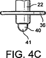
空気経路26は、他端部が頭部20の下方面上に設けられた形成部30と連通し、頭部20は開放式チャンバを有し、チャンバには通気管22が空気を通さないように押し込まれて嵌合している。通気管22は容器の底部近くに下方に延在しており、かつその下方端部には逆止弁34を含む。図示された実施形態において、弁34は公知のダックビル弁を含み、この弁により空気の経路が容器内部に向かう一方向となされ、液体の流れが反対方向の通気管22に向かうことを防止する。通気管22の下方端部32にはまた、弁フランジ部36が設けられて、図示された実施形態において弁34と一体に形成され、かつ双方は押し嵌合されるかまたは、通気管22と空気を通さないように連結されている。
弁フランジ部36は例えばリング部を通気管22の周りおよび同心円上に形成し、かつ羽弁またはリブ部により連結されてもよい。弁フランジ部により、改良された混合を可能にするとともに、弁34が任意の理由により取り外されなければならない場合が生じた際には、窒息の危険を防止することができる。
The
For example, the
使用時には、首部導入部18は弁34とフランジ部36とを通気管22に嵌合することにより、かつ通気管の他方の端部を頭部20の対応する形成部30に嵌合することにより組み立てられ、あるいは予めこのように組み立てられたものを用いる。容器16は満たされ、かつ首部導入部18は容器16の上部唇部上に配置される。乳首12は次いで首部導入部18の頂部に配置され、上記に詳細が説明されたように留め輪14を回し嵌めすることによりアセンブリが液体密封される。混合が必要な際には弁フランジ部36のおかげで、より容易になされる。容器が逆になされると、液体は容器16から首部導入部18内の液体管路部24を介して、乳首12に流れこむ。乳児が乳首12を吸引すると、容器内の圧力低下を招き、空気が空気経路26、通気管22、弁34を介して容器内に入り、圧力が均衡化されるとともに真空蓄積が大幅に低減する。
In use, the
図2を参照すると、首部導入部18の頭部20がより詳細に示されている。図示されるように頭部は、略ディスク形状でかつ容器16(図示されず)の首部の周りに密封部を設けるフランジ部28と、フランジ部の平面部に対して垂直な方向に液体管路部24とを含む。空気経路26はフランジ部28の円筒形の壁部を貫通して通常はフランジ部28の中央部に達し、形成部30と通気管22(図示せず)に経路を提供する。
Referring to FIG. 2, the
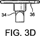
図3aないし3eを参照すると、弁34および弁フランジ36の詳細が示されており、特に、リング形状のまたは他の形状のフランジ36が設けられて、図示されるように例えば開口された羽弁37により弁34が取り付けられた中央ハブ35から延在するスポークのおかげで、このフランジ36は任意の適切な態様で取り付けられている。
Referring to FIGS. 3a-3e, details of the
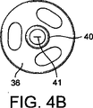
図4a、4b、4cは、本発明の実施形態において実施されてもよい他の一方行の通気弁を示す。半球状の弁40は、中央の細長い開口41を有する半球形状の薄膜を含み、これにより空気が中を通る経路が可能となる。十文字形などの任意の適切な切り込みもまた可能である。細長い開口または切り込みは低圧通気および高圧密封を可能にするような大きさになされる。
Figures 4a, 4b, 4c show another one-line vent valve that may be implemented in embodiments of the present invention. The
図4aないし4cの半球状の弁はまた他の適用分野に用いられてもよい。たとえば、乳首の頂上に配置して液体が内部を通過できるようにしてもよいし、あるいは乳首のフランジ部上に配置して空気が内部を通過できるようにしてもよい。 The hemispherical valves of FIGS. 4a-4c may also be used in other applications. For example, it may be placed on the top of the nipple to allow liquid to pass through it, or it may be placed on the flange of the nipple to allow air to pass through it.
弁34または40の大きさ、材料および構造は、ボトルにとって自然な授乳行為を得る点において特に重要である。現在公知の弁システムは大抵、約50ミリバール(ミリバール)で乳首の通気が可能であるが、これはたとえば剛性により細長い開口部を取り囲む弁壁部の弾力性により決められる閉鎖力によるものである。この結果として使用に際しては、通気が行なわれる前に乳児は不自然に高い吸引力を使わなければならず、このことにより問題が生じるとともに、その吸引行為は自然の授乳時に必要とされるものより強大なものとなる。しかしながら公知のシステムにおいては、このように高い弾力性閉鎖力は、例えば乳児が乳首に絞り圧力を加えた場合には、通気管内部にミルクを確実にもらさないために必要とされる。
The size, material and structure of the
また他方、本発明にしたがった弁34または40は、負の圧力が1から25ミリバールの範囲であるように、より好ましくは5から15ミリバール、最も好ましくは10ミリバールであるように構成されており、これにより乳児が哺乳瓶から吸引した場合、十分に弁を開いて通気を可能にし、乳児による吸引を大幅に低減するとともにより自然な授乳行為が得られる。本発明によると、このことは特に以下の認識に基づいてなされる。哺乳瓶が垂直な状態(ひいては弁がミルクに含浸されている場合)にのみ、ミルクが弁および通気管へ漏れることを防止する必要があり、一方で乳児が乳首を吸引しているときには哺乳瓶は上下が逆になっており、弁はミルクの水平面より上に位置されている。ミルクに含浸されて弁が開いている場合でさえも、液体は弁および通気管に入りこまない。したがって本発明は、弁にとって必要とされる弾力性閉鎖力はより小さくてすむと認識するが、これは哺乳瓶が垂直に立てられた場合には、瓶内のミルクにより加えられた圧力の結果として、弁の両側にさらなる力が加えられるためである。この力は、弁および通気管への漏れを防止するのに十分なさらなる閉鎖力を提供する。
On the other hand, the
したがってこの位置が上下逆である哺乳瓶から乳児が飲む場合には、弁の持つ弾力性閉鎖力はより小さいために、弁はより低い負の圧力下で開き、この結果としてより自然な授乳行為がなされる。 Therefore, when an infant drinks from a baby bottle whose position is upside down, the valve has less elastic closing force, so the valve opens under lower negative pressure, resulting in more natural feeding Is made.
本願明細書を読む当該技術に携わる者であれば適切なダックビル弁または半球状の弁を製作して、ルーチンの試行および実験を用いて上述された基準を満たすことができることを理解されたい。このことはたとえば壁部または薄膜の厚さひいては弁の剛性を変更したり、あるいは所望の圧力での通気を得るために適切な負の圧力を加えたりすることにより、ならびに/もしくは乳児の飲むミルクまたは他の流体の濃度と同様の液体に、例えば5から10cmの圧力の適切な頭部を有する弁を含浸することにより可能となる。弁は例えば5mmの低い頭部の圧力でも閉じられたままで製作されることが好ましい。 Those of ordinary skill in the art reading this specification should appreciate that suitable duckbill or hemispherical valves can be made to meet the above criteria using routine trials and experiments. This may occur, for example, by changing the wall or membrane thickness and thus the stiffness of the valve, or by applying an appropriate negative pressure to obtain aeration at the desired pressure and / or the milk the infant drinks. Alternatively, it is possible by impregnating a liquid with the same concentration of other fluids with a valve having a suitable head, for example with a pressure of 5 to 10 cm. The valve is preferably made to remain closed even with a low head pressure, for example 5 mm.
図3aないし図3eに関して示される具体的な実施形態において弁は通常、30から60のショアA硬さを有するシリコーンゴムで形成され、これはGE、Bayer、Dow、Wacker、Rhone Poulencなどの任意のシリコーン業者より入手できる。
液体シリコーンおよび圧縮成形シリコーンの等級は双方とも、くりかえされる熱滅菌法で重要な熱高熱安定性を提供するものであるため、本発明にとって適切である。他の等級もまた適切である。弁壁の弁は厚みが0.5mmである。前面から見るとダックビル弁は、高さが10.0mm、底部が8.0mmの逆三角形の形状を形成する。側面から見るとダックビル弁は、断面が幅7.0mmの略矩形である。細長い開口は長さ2.5mmから4mmの切り込みにより弁の出口端部に形成されている。この構成により所望の動作範囲が得られるとともに、特にわずか10ミリバールの負の圧力下で開くことができる性能が得られることが見出された。
In the specific embodiment shown with respect to FIGS. 3a-3e, the valve is typically formed of silicone rubber having a Shore A hardness of 30 to 60, which may be any of GE, Bayer, Dow, Wacker, Rhone Poulenc, etc. Available from silicone suppliers.
Both liquid silicone and compression molded silicone grades are suitable for the present invention as they provide important thermal high thermal stability in repeated thermal sterilization processes. Other grades are also appropriate. The valve of the valve wall has a thickness of 0.5 mm. When viewed from the front, the duckbill valve has an inverted triangular shape with a height of 10.0 mm and a bottom of 8.0 mm. When viewed from the side, the duckbill valve has a substantially rectangular cross section with a width of 7.0 mm. The elongated opening is formed at the outlet end of the valve by a notch with a length of 2.5 mm to 4 mm. It has been found that this arrangement provides the desired operating range and the ability to open in particular under a negative pressure of only 10 mbar.
図4aないし図4cに関連して示される具体的な実施形態において半球状の弁は通常、30から60のショアA硬さを有するシリコーンゴムで形成され、これはGE、Bayer、Dow、Wacker、Rhone Poulencなどの任意のシリコーン業者より入手できる。液体シリコーンおよび圧縮成形シリコーンの等級は双方とも、くりかえされる熱滅菌法で重要な熱高熱安定性を提供するものであるため、本発明にとって適切である。他の等級もまた適する。高温密閉用の半球状の弁40の要となる寸法は、その半径、壁厚、中央の細長い開口部41の長さおよび材料の柔軟性である。半球状の弁は半径が2mmから5mmであり、最も好ましくは3.5mmであり、かつ壁厚は0.3mmから0.7mmであり、最も好ましくは0.5mmである。中央の細長い開口部の寸法は、2.5mmから4.0mmの範囲である。この構成により低い水平面での吸引が得られるが、この構成はまた漏れなしで沸点温度までの液体に対する圧力に耐える本質的に十分強いものであることが判明した
In the specific embodiment shown in connection with FIGS. 4a to 4c, the hemispherical valve is typically formed of silicone rubber having a Shore A hardness of 30 to 60, which can be GE, Bayer, Dow, Wacker, Available from any silicone vendor such as Rhone Poulenc. Both liquid silicone and compression molded silicone grades are suitable for the present invention as they provide important thermal high thermal stability in repeated thermal sterilization processes. Other grades are also suitable. The key dimensions of the
図5aおよび図5bは、他の空気入れシステムを有する本発明の第2の実施形態を示す。
空気経路は乳首12のフランジ部上の空気流入開口部51により形成され、かつ空気管路部材50は乳首から下方に突出する。空気管路部材50は空気と通気管22との間の連通を提供するが、この通気管は空気を通さない押し嵌合により、空気管路部材に取り付けられる。空気管路部材50は乳首12のフランジ部上に形成されてもよく、これは例えば乳首開孔51で乳首から下方に突出する茎部の形状によりなされてもよい。乳首12は容器16に回し嵌め式留め輪14により取り付けられる。
Figures 5a and 5b show a second embodiment of the present invention having another inflator system.
The air path is formed by an
本発明の第3の実施形態において、図6で示されるように、空気管路部材56は、例えば密閉リング52の形状で支持部材上に一体的に形成される。空気管路部材56は、密閉リング52の下方に突出する。密閉リング52は容器16と同様の径を有し、容器の唇部に嵌合して配置されて、乳首12のフランジ部が回し留め輪14により押下されて、液体が入らないような状態に保持される。密閉リング52はさらに、乳首12のフランジ部に支持部を設ける。乳首12のフランジ部には凹部55が形成され、乳首の空気流入開口53につながっている。フランジ凹部55と回し嵌め式留め輪14との間には空気経路が形成され、これにより周辺部から、乳首のフランジ部の開孔53を介して空気が通過できるようになるが、破線矢印54で示されるように、空気経路は密閉リング52上の管路部材56上に、かつ管路部材56は通気管22に適切に一直線に並べられる。
通気管は空気を通さない押し嵌合により、空気管路部材56に取り付けられる。
In the third embodiment of the present invention, as shown in FIG. 6, the
The vent pipe is attached to the
図7aないし図7dは、他の哺乳瓶導入頭部70を示す。図示されるように頭部はスポーク部73により、リム部72に連結される。液体管路はハブ部71とリム部72およびスポーク73との間の空間74により形成される。液体管路は容器16と乳首12との間の連通を提供し(いずれも図示せず)このため哺乳瓶が上下逆にされると、液体が容器から空間74を介して乳首内に流れ込み、乳児は吸乳が可能になる。
FIGS. 7 a to 7 d show another baby
スポーク75のうちの少なくとも1つに十分な厚みがあれば、略放射状の孔がこの中に形成され、開放型のチャンバ77に空気経路76を提供する。空気経路76は通気管22と連通し(図示せず)、開放型のチャンバ77に押し嵌合により取り付けられ、かつ頭部70から下方に回し嵌め式留め輪14(図示せず)のねじ山を介して、空気中に突出する。
If at least one of the
略環状の形状をしたリム部72の下側の環状の凹部78は、頭部と容器12(図示せず)との間に液体を通さない密封部を設ける。凹部78は、内部表面79が容器内部に嵌合し、かつ上部表面部80が容器の唇部上に載置されるように形成される。
An
上述された哺乳瓶の種々の部分は、任意の適切な材料により製作されてもよいとともに、特に乳首12、回し留め輪14および容器16は任意の標準の材料で製作されてもよいことを理解されたい。通気管22は、たとえばプラスチック類などの概ね剛性で不活性の材料で製作されることが好ましく、かつ弁34および40は所望の目的にしたがってシリコーンゴムまたは他の適切な材料で製作されてもよい。フランジ部36は混合および窒息防止機能を可能にする剛性のプラスチック材料で製作されることが好ましく、かつ必要に応じて弁34および40を備えた二個取成形であってもよい。上述された実施形態においては、種々の要素が容易に取り外しおよび洗浄ができる押し嵌合により連結されているが、任意の適切な連結の態様が採用されてもよく、必要に応じて種々の部分が一体的に形成されるかあるいは取り外し不可に形成されてもよい。頭部20は半剛性の材料で製作されることが好ましく、これにより空気経路26はフランジ部28の変形により閉鎖されることが確実に避けられると同時に、容器の首部には高信頼性の液体を通さない密封部が設けられる。同様に第3の実施形態の支持部材は半剛性の材料で製作されることが好ましく、これにより空気管路部材56は通気管22に押し嵌合された場合、変形により閉鎖されることが確実に避けられると同時に、容器16の首部には高信頼性の液体を通さない密封部が設けられる。
It will be appreciated that the various parts of the baby bottle described above may be made of any suitable material, and in particular the
首部導入部18は容器/回し留め輪に一体化されてもよく、あるいは洗浄目的で必要な場合は取り外されてもよい。特に首部導入部18は標準の哺乳瓶に、簡単に規格化されて取り付けられ、かつ多くの場合には、既存の回し留め輪は首部導入部18と協働して用いられてもよい。また首部導入部18は適切な深さを有する留め輪を設けられて、優れたねじ山係合を確実なものにしてもよい。
The
本願明細書で示された構造により種々の利点がもたらされる。弁は極めて低圧で通気することにより自然な授乳を可能にする。通気管22は基部で弁止めされているため、乳児が乳首を変形させて乳首から液体を押し出すことなく、容器内部の圧力均衡化が得られる。また、弁は液体密封部を提供するため、液体が首部導入部を介して容器側面に落ちて漏れる危険は全くなくなる。首部導入部には単純で規格化された構成が設けられる。弁フランジが追加されたおかげで、混合および攪拌が改良できる一方で、窒息の危険が防止できる。
Various advantages are provided by the structure shown herein. The valve allows natural breastfeeding by venting at very low pressure. Because the
上述されたダックビル弁または半球状の弁の代わりに任意のタイプの適切な弁が用いられてもよいことは当業者なら理解されるであろう。容器および種々の構成部分の寸法は必要に応じて変更されてもよく、かつ種々の構成要素の具体的な配置は必要に応じて再構成されてもよい。同様に弁フランジに関して他の任意の適切な形状および配置が適用されてもよい。上記の説明は哺乳瓶に関してなされてきたが、同様の方法は圧力均衡化を設けることを所望する任意のタイプのマウスピースあるいは給水または飲用閉鎖部を備えた任意の飲用器に用いられてもよい。 One skilled in the art will appreciate that any type of suitable valve may be used in place of the duckbill or hemispherical valve described above. The dimensions of the container and the various components may be varied as needed, and the specific arrangement of the various components may be reconfigured as needed. Similarly, any other suitable shape and arrangement for the valve flange may be applied. Although the above description has been made with reference to a baby bottle, a similar method may be used for any type of mouthpiece or any drinking device with a water supply or drinking closure where it is desired to provide pressure balancing. .
Claims (10)
乳首と、
ベントアセンブリと、を含む哺乳瓶であって、
前記ベントアセンブリは、
前記容器と前記乳首とを隔てる頭部と、
前記頭部から下方へ突出する通気管と、を含み、
前記頭部は、
前記容器と前記乳首との間に連通を提供する少なくとも1つの液体管路部と、
前記液体管路部から分離され、一端部を前記通気管に、かつ他端部を空気に連通する空気経路と、を含み、
前記通気管は、前記容器の底部近くまで下方に延在していて、その下方端部には、前記容器内に向かう一方向の空気の経路を許容し、かつ、前記通気管内に向かう反対方向の液体の流れを防止する逆止弁、および、当該逆止弁の上部から横方向に延びて一体に形成された弁フランジが接続されており、
前記逆止弁は、1ミリバールから25ミリバールの範囲の負の圧力で通気するように構成されている、
哺乳瓶。A container,
Nipples,
A baby bottle comprising a vent assembly,
The vent assembly includes:
A head separating the container and the nipple;
A vent pipe projecting downward from the head,
The head is
At least one liquid conduit providing communication between the container and the nipple;
An air path that is separated from the liquid pipe part, communicates one end with the vent pipe and the other end with air,
The vent pipe extends downward to near the bottom of the container, and allows a one-way air path into the container at the lower end thereof, and in the opposite direction toward the vent pipe. A check valve that prevents the flow of liquid, and a valve flange that is integrally formed extending laterally from the top of the check valve,
The check valve is constructed from 1 mbar to vent at a negative pressure in the range of 25 mbar,
baby bottle.
Applications Claiming Priority (3)
| Application Number | Priority Date | Filing Date | Title |
|---|---|---|---|
| GB0410993.0 | 2004-05-17 | ||
| GBGB0410993.0A GB0410993D0 (en) | 2004-05-17 | 2004-05-17 | Feeding bottle |
| PCT/GB2005/001883 WO2005112869A1 (en) | 2004-05-17 | 2005-05-17 | Feeding bottle |
Related Child Applications (1)
| Application Number | Title | Priority Date | Filing Date |
|---|---|---|---|
| JP2009191709A Division JP2009273912A (en) | 2004-05-17 | 2009-08-21 | Feeding bottle |
Publications (2)
| Publication Number | Publication Date |
|---|---|
| JP2007515976A JP2007515976A (en) | 2007-06-21 |
| JP4847757B2 true JP4847757B2 (en) | 2011-12-28 |
Family
ID=32607462
Family Applications (2)
| Application Number | Title | Priority Date | Filing Date |
|---|---|---|---|
| JP2005517156A Expired - Fee Related JP4847757B2 (en) | 2004-05-17 | 2005-05-17 | baby bottle |
| JP2009191709A Pending JP2009273912A (en) | 2004-05-17 | 2009-08-21 | Feeding bottle |
Family Applications After (1)
| Application Number | Title | Priority Date | Filing Date |
|---|---|---|---|
| JP2009191709A Pending JP2009273912A (en) | 2004-05-17 | 2009-08-21 | Feeding bottle |
Country Status (13)
| Country | Link |
|---|---|
| US (1) | US7798347B2 (en) |
| EP (1) | EP1755524B1 (en) |
| JP (2) | JP4847757B2 (en) |
| KR (1) | KR101273968B1 (en) |
| CN (1) | CN1972660B (en) |
| AU (1) | AU2005244643B2 (en) |
| CA (1) | CA2565507C (en) |
| ES (1) | ES2552032T3 (en) |
| GB (1) | GB0410993D0 (en) |
| NZ (1) | NZ551239A (en) |
| PL (1) | PL1755524T3 (en) |
| TW (1) | TWI337862B (en) |
| WO (1) | WO2005112869A1 (en) |
Families Citing this family (46)
| Publication number | Priority date | Publication date | Assignee | Title |
|---|---|---|---|---|
| US8113365B2 (en) * | 2000-05-08 | 2012-02-14 | New Vent Designs Inc. | Fully vented nursing bottle with single piece vent tube |
| US20110233236A1 (en) * | 2010-03-25 | 2011-09-29 | Brown Craig E | Continuous, complete, automatic, non-leaking, non-aerating, positive pressure one-piece vent and pouring combination utilizing one direct venting aperture |
| KR100954853B1 (en) * | 2008-03-04 | 2010-04-28 | 박용직 | Environment hormone preventing nursing bottle |
| ES2343230B1 (en) * | 2007-07-17 | 2011-04-28 | Marcelino Ferri Garcia | THREADED DEVICE WITH AIR VALVE TO PERFECT CONVENTIONAL BIBERON CONTAINER CONTAINER. |
| WO2009010620A1 (en) * | 2007-07-17 | 2009-01-22 | Ferri Garcia Marcelino | Improved feeding bottle |
| US8863969B2 (en) * | 2007-09-04 | 2014-10-21 | Chantal Lau | Feeding bottle system |
| US10138034B2 (en) * | 2008-01-29 | 2018-11-27 | Craig E Brown | Singular cap compound vented nursing and related bottle |
| US10137059B2 (en) * | 2008-01-29 | 2018-11-27 | Craig E Brown | Nursing bottle with integrated collar and nipple flange venting structure |
| DE102008027606A1 (en) * | 2008-06-10 | 2009-12-17 | Novatex Gesellschaft mit beschränkter Haftung Gummi- und Plastikwaren | Ventilation device for a drinking bottle |
| CH698956A1 (en) * | 2008-06-12 | 2009-12-15 | Medela Holding Ag | Teat. |
| GB0811050D0 (en) * | 2008-06-17 | 2008-07-23 | U Pol Ltd | A Connector for a gravity feed spray gun, a gravity feed spray gun and a method of preparing a spray paint |
| US7984818B1 (en) * | 2008-06-30 | 2011-07-26 | Dominick Joseph Fucito | Vented nursing bottle with leak prevention means |
| CN101332154B (en) * | 2008-07-11 | 2013-06-12 | 东莞市银燕塑料容器有限公司 | Return-air feeder |
| CN201346316Y (en) * | 2009-01-19 | 2009-11-18 | 广州健士婴童用品有限公司 | Feeder air return system |
| US20100308003A1 (en) * | 2009-06-04 | 2010-12-09 | Adiri, Inc. | Modular and Natural Infant Feeding Container |
| CH701676A1 (en) * | 2009-08-20 | 2011-02-28 | Medela Holding Ag | Teat. |
| US20110100945A1 (en) * | 2009-09-24 | 2011-05-05 | Henry Alfonso Gutierrez | Vent system for a dispensing unit |
| USD644334S1 (en) | 2010-03-11 | 2011-08-30 | Medical Instill Technologies, Inc. | Bottle with nipple |
| US20160046421A1 (en) * | 2010-03-25 | 2016-02-18 | Craig E. Brown | Sectionalized fluids container |
| US20120192977A1 (en) * | 2011-01-27 | 2012-08-02 | Tsao Yu-Yao | Duck-billed check valve |
| US8967405B2 (en) | 2011-08-31 | 2015-03-03 | Light Bulb Inventions, Llc | Venting baby bottle |
| US10100402B2 (en) | 2011-10-07 | 2018-10-16 | International Business Machines Corporation | Substrate holder for graphene film synthesis |
| USD720464S1 (en) | 2012-08-22 | 2014-12-30 | Tomy International, Inc. | Baby bottle |
| BR112015015967A2 (en) * | 2013-01-10 | 2017-07-11 | Handi Craft Co | dual configuration bottle set |
| CN103405344B (en) * | 2013-05-24 | 2015-09-23 | 孙庆扬 | A kind of feeding bottle with return-air function |
| US10166172B2 (en) | 2013-07-10 | 2019-01-01 | Handi-Craft Company | Dual configuration bottle assembly |
| US10226402B2 (en) | 2014-02-16 | 2019-03-12 | T.T.Y. General Trade Lines Ltd | Vented liquid container |
| USD865191S1 (en) | 2016-08-03 | 2019-10-29 | Craig E Brown | Vented nursing bottle nipple |
| US20190210775A1 (en) * | 2014-06-24 | 2019-07-11 | Craig E. Brown | Universal Single Piece Venting Insert For Container |
| US9907731B2 (en) | 2014-11-20 | 2018-03-06 | Chantal Lau | Self-paced ergonomic infant feeding bottle |
| US10085920B2 (en) * | 2015-03-09 | 2018-10-02 | Benir Baby, LTd | Vented baby bottle |
| FR3035321B1 (en) * | 2015-04-24 | 2021-04-02 | Cva Tech Pure Silicone Group Ag | BREASTFEEDING DEVICE AND ASSOCIATED BOTTLE |
| US10195117B2 (en) | 2015-06-03 | 2019-02-05 | James J. Britto | Vented bottle |
| US11596580B2 (en) * | 2016-03-03 | 2023-03-07 | Qingyang SUN | Nursing bottle having air returning function |
| ES2962445T3 (en) * | 2016-04-21 | 2024-03-19 | Mayborn Uk Ltd | valve assembly |
| CN106860025B (en) * | 2017-03-06 | 2024-02-06 | 浙江帅宝塑胶制品有限公司 | Feeding bottle |
| CA3090814A1 (en) | 2018-03-02 | 2019-09-06 | Handi-Craft Company | Bottle assembly |
| EP3598964B1 (en) * | 2018-07-23 | 2021-06-09 | Koninklijke Philips N.V. | Partitioning component for a feeding bottle device and feeding bottle device |
| USD935630S1 (en) * | 2018-11-01 | 2021-11-09 | Thermos L.L.C. | Sleeve for a baby bottle |
| EP3677239A1 (en) * | 2019-01-02 | 2020-07-08 | Koninklijke Philips N.V. | Baby bottle device |
| CN109621041A (en) * | 2019-01-23 | 2019-04-16 | 滨海昌正企业管理有限公司 | A kind of collection milk device being hidden in inside breast pump host |
| CA186685S (en) * | 2019-03-04 | 2020-02-21 | Upis Co Ltd | Feeding bottle |
| USD919822S1 (en) * | 2019-04-22 | 2021-05-18 | Rengao Wang | Feeding bottle |
| NL2023437B1 (en) * | 2019-07-04 | 2021-02-02 | Dethapak Innovation B V | Pour spout for facilitating pouring a liquid from a container |
| EP3878427A1 (en) * | 2020-03-13 | 2021-09-15 | Koninklijke Philips N.V. | Partitioning component for a feeding bottle |
| GB202204192D0 (en) * | 2022-03-24 | 2022-05-11 | Mayborn Uk Ltd | Venting member, feeding bottle, and method of forming a venting member |
Family Cites Families (95)
| Publication number | Priority date | Publication date | Assignee | Title |
|---|---|---|---|---|
| US71570A (en) * | 1867-12-03 | Mikel beck | ||
| US380835A (en) * | 1888-04-10 | Waltee f | ||
| GB191204210A (en) | 1912-02-20 | 1912-06-13 | Arnold Prox | Improvements in Rubber Teats for Feeding Bottles. |
| US3207349A (en) * | 1963-12-18 | 1965-09-21 | George B Rabe | Nursing bottle |
| US3704803A (en) * | 1971-07-13 | 1972-12-05 | Charles L Ponder | Nursing bottle |
| GB1453968A (en) * | 1972-12-07 | 1976-10-27 | Tonkin S L | Artificial baby feeding |
| FI831194L (en) | 1983-04-08 | 1984-10-09 | Byong Wha Suh | NAPPFLASKA. |
| GB2154451B (en) | 1984-02-01 | 1988-04-27 | Avent Medical Ltd | Improvements in baby feed bottles |
| GB2167735A (en) | 1984-11-21 | 1986-06-04 | Khung Ngee Tan | Teat |
| DE8524734U1 (en) * | 1985-08-29 | 1986-04-03 | Helvoet Pharma N.V., 3820 Alken | Orthodontic bottle teat |
| JP2741868B2 (en) | 1988-06-13 | 1998-04-22 | ピジョン株式会社 | Nipples with caps for baby bottles |
| JP2622598B2 (en) | 1988-11-28 | 1997-06-18 | ピジョン株式会社 | Baby nipples |
| JPH02161950A (en) * | 1988-12-15 | 1990-06-21 | Jiekusu Kk | Nipple |
| GB9023707D0 (en) * | 1990-10-31 | 1990-12-12 | Sepehr Fereidoon | Baby bottle with an automatic air inlet valve |
| JPH0584279A (en) | 1991-09-30 | 1993-04-06 | Pigeon Corp | Nipple for nursing bottle |
| JPH05115535A (en) | 1991-10-30 | 1993-05-14 | Pigeon Corp | Nipple for nursing bottle |
| DE69423884T2 (en) * | 1993-05-18 | 2000-11-16 | Procter & Gamble | LIQUID TANK |
| US5474028A (en) * | 1994-01-25 | 1995-12-12 | Merrick's, Inc. | Animal feeding nipple |
| USD486579S1 (en) | 1994-11-03 | 2004-02-10 | Munchkin, Inc. | Baby bottle nipple |
| US5544766A (en) * | 1994-11-04 | 1996-08-13 | Munchkin Bottling Inc. | Coded two part nipple members for baby bottles and method of making |
| FR2732590B1 (en) * | 1995-04-10 | 1997-06-20 | Busnel Marie Claire | TEAT FOR BOTTLE, AS WELL AS A BOTTLE EQUIPPED WITH SUCH A TEAT |
| US5678710A (en) * | 1995-07-12 | 1997-10-21 | Sheu; Miin-Tsang | Nipple for nursing bottles |
| US5570796A (en) * | 1995-08-04 | 1996-11-05 | Brown; Craig E. | Nursing bottle with an air venting structure |
| US5779071A (en) | 1995-08-04 | 1998-07-14 | New Vent Designs, Inc. | Nursing bottle with an air venting structure |
| USD384748S (en) | 1995-11-09 | 1997-10-07 | Munchkin, Inc. | Baby bottle nipple |
| GB9523215D0 (en) * | 1995-11-13 | 1996-01-17 | Petro Man Ltd | Filling of tanks with volatile liquids |
| DE19716534A1 (en) | 1996-04-23 | 1997-11-06 | Heike Rummel | Teat for baby's bottle |
| US5881893A (en) * | 1996-12-21 | 1999-03-16 | Playtex Products, Inc. | Leakproof nipple valve |
| WO1998025571A1 (en) | 1996-12-11 | 1998-06-18 | Playtex Products, Inc. | Leakproof nipple valve |
| USD412582S (en) | 1997-04-14 | 1999-08-03 | Playtex Products, Inc. | Combined nipple and ring |
| US6032810A (en) * | 1997-07-17 | 2000-03-07 | Gerber Products Company | One-piece nipple/collar for nursers and the like |
| USD404138S (en) | 1997-07-17 | 1999-01-12 | Gerber Products Company | Combined nipple and collar |
| US6161710A (en) * | 1997-11-03 | 2000-12-19 | Dieringer; Mary F. | Natural nipple baby feeding apparatus |
| USD405530S (en) | 1997-11-04 | 1999-02-09 | Playtex Products, Inc. | Rounded tip nipple |
| USD454642S1 (en) * | 1997-11-21 | 2002-03-19 | Nouri E. Hakim | Baby bottle |
| GB9802095D0 (en) * | 1998-01-30 | 1998-03-25 | Cannon Rubber Ltd | Closure assembly |
| JP4049451B2 (en) | 1998-06-16 | 2008-02-20 | ピジョン株式会社 | Beverage container |
| US6112919A (en) | 1998-07-13 | 2000-09-05 | Ho; Shu-E | Leakage preventive device for milk bottles or the like |
| US20050288712A9 (en) * | 1998-08-21 | 2005-12-29 | Hakim Nouri E | Pacifier and baby bottle nipple systems |
| US20020030029A1 (en) * | 1998-08-21 | 2002-03-14 | Hakim Nouri E. | Pacifier shields |
| US6241110B1 (en) * | 1998-08-21 | 2001-06-05 | Nouri E. Hakim | Baby products and methods of manufacture |
| USD421306S (en) | 1998-10-13 | 2000-02-29 | Gerber Products Company | Combined nipple and collar |
| JP2000189496A (en) | 1998-10-20 | 2000-07-11 | Pigeon Corp | Artificial nipple |
| DE19849271A1 (en) * | 1998-10-26 | 2000-04-27 | Herbert Willmann | Drinking bottle, e.g. a baby bottle, comprises a neck with an outer thread and a lid with a base opening and a ring shaped insert |
| US6068147A (en) * | 1998-11-24 | 2000-05-30 | Sheu; Miin-Shiou | Air intake aiding plate for nipples of feeding bottles |
| US6645228B2 (en) * | 2001-11-13 | 2003-11-11 | Playtex Products, Inc. | Nipple |
| US7122045B2 (en) * | 2001-11-13 | 2006-10-17 | Playtex Products, Inc. | Nipple |
| US7326234B2 (en) * | 1998-12-10 | 2008-02-05 | Playtex Products, Inc. | Vented bottle |
| EP1161219B8 (en) | 1999-03-17 | 2009-09-09 | Morrill, Jennifer | Infant feeding container |
| JP3209271B2 (en) | 1999-03-29 | 2001-09-17 | ジェクス株式会社 | Baby bottle nipples |
| USD441870S1 (en) | 1999-10-20 | 2001-05-08 | Playtex Products, Inc. | Nipple |
| GB0004210D0 (en) | 2000-02-23 | 2000-04-12 | Mead Corp | Carton and carton blanks |
| USD444239S1 (en) | 1999-11-12 | 2001-06-26 | Jex Co., Ltd. | Nipple |
| US20020063103A1 (en) * | 1999-12-13 | 2002-05-30 | Kathleen Kiernan | Nipple for nursing bottle |
| JP3380201B2 (en) | 1999-12-16 | 2003-02-24 | ピジョン株式会社 | Artificial nipple |
| JP3405304B2 (en) | 1999-12-28 | 2003-05-12 | ジェクス株式会社 | pacifier |
| JP4233074B2 (en) | 2000-04-24 | 2009-03-04 | ピジョン株式会社 | Artificial nipple |
| JP2002011076A (en) | 2000-04-24 | 2002-01-15 | Pigeon Corp | Artificial nipple |
| JP4233075B2 (en) | 2000-04-27 | 2009-03-04 | ピジョン株式会社 | Artificial nipple |
| CN2428128Y (en) * | 2000-06-27 | 2001-05-02 | 邓立新 | Feeding bottle with non-return intake valve |
| JP2002200144A (en) | 2000-12-28 | 2002-07-16 | Pigeon Corp | Fixing utensil for artificial nipple, fixing utensil having artificial nipple and nursing bottle |
| JP2002306572A (en) | 2001-04-11 | 2002-10-22 | Pigeon Corp | Nipple for nursing bottle and its production method |
| USD464434S1 (en) | 2001-08-20 | 2002-10-15 | Munchkin, Inc. | Bottle with nipple |
| USD463567S1 (en) | 2001-08-20 | 2002-09-24 | Munchkin, Inc. | Nipple |
| US6499615B1 (en) | 2001-09-11 | 2002-12-31 | William K. Szieff | Angled cap and vent for use with a baby bottle |
| GB2380186A (en) | 2001-09-28 | 2003-04-02 | Cannon Rubber Ltd | Thick feed baby teat |
| USD488560S1 (en) | 2001-10-29 | 2004-04-13 | Playtex Products, Inc. | Nipple |
| USD465028S1 (en) | 2001-10-29 | 2002-10-29 | Playtex Products, Inc. | Nipple |
| JP3992477B2 (en) | 2001-11-09 | 2007-10-17 | ピジョン株式会社 | Artificial nipples and suckers |
| JP4289592B2 (en) | 2001-11-09 | 2009-07-01 | ピジョン株式会社 | Artificial nipples and baby bottles |
| USD459815S1 (en) | 2001-11-20 | 2002-07-02 | Edward J. Pastucha | Combined baby bottle nipple and bottle cap for fitting on water bottles |
| US20030106872A1 (en) * | 2001-12-10 | 2003-06-12 | Hung-Hsiu-Hua Lin | Nipple with air intake valve |
| USD520142S1 (en) | 2002-03-15 | 2006-05-02 | Baby Innovations Marketing E | Teat |
| WO2003092577A1 (en) | 2002-05-03 | 2003-11-13 | Munchkin, Inc. | Variable flow infant feeding assembly |
| DE20210121U1 (en) * | 2002-06-29 | 2002-10-02 | Sheu Miin Tsang | Milk bottle teat with extension tube to protect against stomach bloating |
| GT200300162A (en) * | 2002-08-05 | 2008-01-21 | ANTI DRINK PRODUCT - SPILL. | |
| JP3916543B2 (en) | 2002-10-11 | 2007-05-16 | ピジョン株式会社 | Baby bottle |
| USD504723S1 (en) | 2002-10-15 | 2005-05-03 | Playtex Products, Inc. | Nipple |
| USD479606S1 (en) | 2002-10-15 | 2003-09-09 | Playtex Products, Inc. | Nipple |
| US7150370B2 (en) * | 2002-10-21 | 2006-12-19 | Sung-Hwan Pyun | Air venting apparatus for milk bottle |
| AT413979B (en) | 2003-01-20 | 2006-07-15 | Bamed Ag | DRINKING-NOSE |
| AT413978B (en) | 2003-01-20 | 2006-07-15 | Bamed Ag | AIR VALVE FOR A LID OF A DRINKING CONTAINER |
| US20040188373A1 (en) * | 2003-03-25 | 2004-09-30 | Lewis Julie Maureen | Vented, low-drip nursing bottle |
| AT6721U1 (en) | 2003-04-29 | 2004-03-25 | Bamed Ag | MAMMAL |
| US6984688B2 (en) * | 2003-05-02 | 2006-01-10 | Gls Corp | Injection-moldable transparent thermoplastic elastomer |
| US20040226906A1 (en) * | 2003-05-12 | 2004-11-18 | Johan Peterson | Baby bottle nipple |
| US20040256345A1 (en) * | 2003-06-20 | 2004-12-23 | Lundquist Jon Tyler | Single use recyclable infant feeding bottle |
| GB2412114B (en) | 2004-03-19 | 2007-03-14 | Ilan Zadik Samson | Vented teat |
| JP4035574B2 (en) * | 2004-04-07 | 2008-01-23 | 株式会社パタカラ | Mouthpiece for baby bottle |
| US20050252875A1 (en) * | 2004-05-14 | 2005-11-17 | Miin-Tsang Sheu | Air inlet valve of a nipple used for a bottle |
| JP4813777B2 (en) | 2004-06-29 | 2011-11-09 | ピジョン株式会社 | Artificial nipples and baby bottles |
| US20070045214A1 (en) * | 2004-07-27 | 2007-03-01 | Jennings James E | Nipple spout |
| JP4925295B2 (en) | 2004-07-29 | 2012-04-25 | ピジョン株式会社 | Artificial nipple, baby bottle, and method for manufacturing artificial nipple |
| JP4907069B2 (en) | 2004-09-03 | 2012-03-28 | ピジョン株式会社 | Artificial nipples and baby bottles |
| US20060213859A1 (en) * | 2005-03-25 | 2006-09-28 | Miin-Tsang Sheu | Flatulence-resisting nursing bottle air cap |
-
2004
- 2004-05-17 GB GBGB0410993.0A patent/GB0410993D0/en not_active Ceased
- 2004-08-19 TW TW093124917A patent/TWI337862B/en not_active IP Right Cessation
-
2005
- 2005-05-17 AU AU2005244643A patent/AU2005244643B2/en active Active
- 2005-05-17 PL PL05744834T patent/PL1755524T3/en unknown
- 2005-05-17 CN CN2005800160029A patent/CN1972660B/en active Active
- 2005-05-17 EP EP05744834.2A patent/EP1755524B1/en active Active
- 2005-05-17 CA CA2565507A patent/CA2565507C/en not_active Expired - Fee Related
- 2005-05-17 KR KR1020067026585A patent/KR101273968B1/en not_active IP Right Cessation
- 2005-05-17 WO PCT/GB2005/001883 patent/WO2005112869A1/en active Application Filing
- 2005-05-17 ES ES05744834.2T patent/ES2552032T3/en active Active
- 2005-05-17 NZ NZ551239A patent/NZ551239A/en not_active IP Right Cessation
- 2005-05-17 US US11/596,546 patent/US7798347B2/en active Active
- 2005-05-17 JP JP2005517156A patent/JP4847757B2/en not_active Expired - Fee Related
-
2009
- 2009-08-21 JP JP2009191709A patent/JP2009273912A/en active Pending
Also Published As
| Publication number | Publication date |
|---|---|
| GB0410993D0 (en) | 2004-06-23 |
| TW200538094A (en) | 2005-12-01 |
| PL1755524T3 (en) | 2016-02-29 |
| CN1972660B (en) | 2013-07-17 |
| WO2005112869A1 (en) | 2005-12-01 |
| CA2565507A1 (en) | 2005-12-01 |
| KR20070027593A (en) | 2007-03-09 |
| JP2009273912A (en) | 2009-11-26 |
| NZ551239A (en) | 2011-01-28 |
| JP2007515976A (en) | 2007-06-21 |
| US7798347B2 (en) | 2010-09-21 |
| CA2565507C (en) | 2014-07-08 |
| TWI337862B (en) | 2011-03-01 |
| US20080099422A1 (en) | 2008-05-01 |
| AU2005244643A1 (en) | 2005-12-01 |
| CN1972660A (en) | 2007-05-30 |
| KR101273968B1 (en) | 2013-06-12 |
| EP1755524B1 (en) | 2015-09-02 |
| EP1755524A1 (en) | 2007-02-28 |
| ES2552032T3 (en) | 2015-11-25 |
| AU2005244643B2 (en) | 2011-04-07 |
Similar Documents
| Publication | Publication Date | Title |
|---|---|---|
| JP4847757B2 (en) | baby bottle | |
| JP4991877B2 (en) | Vent valve assembly for baby bottle | |
| US5779071A (en) | Nursing bottle with an air venting structure | |
| JP3787160B2 (en) | Beverage cup with cover | |
| US5079013A (en) | Dripless liquid feeding/training containers | |
| JP5650741B2 (en) | Nipple unit | |
| JP5041560B2 (en) | Lid for beverage containers to prevent liquid leakage | |
| US20110155684A1 (en) | Baby bottle and feeding system | |
| JP2007529374A (en) | Drinking container ventilation system and method | |
| US20040256345A1 (en) | Single use recyclable infant feeding bottle | |
| WO2005027819A2 (en) | Vented bottle | |
| KR20080045286A (en) | Sucker for drinking purposes | |
| KR20130016199A (en) | Bottle assembly having bottom vent | |
| CN109862864B (en) | Feeding bottle device | |
| US20180036207A1 (en) | Baby bottle nipple and configurations thereof | |
| WO2014117209A1 (en) | Drinking container cap with demand valve | |
| CN113277213B (en) | Feeding bottle compatible cap equipped with straw | |
| CN210145107U (en) | Flatulence-preventing feeding bottle convenient and fast to use | |
| US20040226906A1 (en) | Baby bottle nipple | |
| MXPA98000913A (en) | Bibe |
Legal Events
| Date | Code | Title | Description |
|---|---|---|---|
| A131 | Notification of reasons for refusal |
Free format text: JAPANESE INTERMEDIATE CODE: A131 Effective date: 20081118 |
|
| A521 | Request for written amendment filed |
Free format text: JAPANESE INTERMEDIATE CODE: A523 Effective date: 20090218 |
|
| A02 | Decision of refusal |
Free format text: JAPANESE INTERMEDIATE CODE: A02 Effective date: 20090421 |
|
| A521 | Request for written amendment filed |
Free format text: JAPANESE INTERMEDIATE CODE: A523 Effective date: 20090821 |
|
| A911 | Transfer to examiner for re-examination before appeal (zenchi) |
Free format text: JAPANESE INTERMEDIATE CODE: A911 Effective date: 20091014 |
|
| A912 | Re-examination (zenchi) completed and case transferred to appeal board |
Free format text: JAPANESE INTERMEDIATE CODE: A912 Effective date: 20100108 |
|
| A601 | Written request for extension of time |
Free format text: JAPANESE INTERMEDIATE CODE: A601 Effective date: 20110307 |
|
| A602 | Written permission of extension of time |
Free format text: JAPANESE INTERMEDIATE CODE: A602 Effective date: 20110314 |
|
| A601 | Written request for extension of time |
Free format text: JAPANESE INTERMEDIATE CODE: A601 Effective date: 20110407 |
|
| A602 | Written permission of extension of time |
Free format text: JAPANESE INTERMEDIATE CODE: A602 Effective date: 20110414 |
|
| A601 | Written request for extension of time |
Free format text: JAPANESE INTERMEDIATE CODE: A601 Effective date: 20110506 |
|
| A602 | Written permission of extension of time |
Free format text: JAPANESE INTERMEDIATE CODE: A602 Effective date: 20110512 |
|
| A521 | Request for written amendment filed |
Free format text: JAPANESE INTERMEDIATE CODE: A523 Effective date: 20110607 |
|
| A521 | Request for written amendment filed |
Free format text: JAPANESE INTERMEDIATE CODE: A523 Effective date: 20110830 |
|
| A01 | Written decision to grant a patent or to grant a registration (utility model) |
Free format text: JAPANESE INTERMEDIATE CODE: A01 |
|
| A61 | First payment of annual fees (during grant procedure) |
Free format text: JAPANESE INTERMEDIATE CODE: A61 Effective date: 20111014 |
|
| FPAY | Renewal fee payment (event date is renewal date of database) |
Free format text: PAYMENT UNTIL: 20141021 Year of fee payment: 3 |
|
| R150 | Certificate of patent or registration of utility model |
Free format text: JAPANESE INTERMEDIATE CODE: R150 |
|
| LAPS | Cancellation because of no payment of annual fees |