JP4847299B2 - Air conditioner - Google Patents
Air conditioner Download PDFInfo
- Publication number
- JP4847299B2 JP4847299B2 JP2006314759A JP2006314759A JP4847299B2 JP 4847299 B2 JP4847299 B2 JP 4847299B2 JP 2006314759 A JP2006314759 A JP 2006314759A JP 2006314759 A JP2006314759 A JP 2006314759A JP 4847299 B2 JP4847299 B2 JP 4847299B2
- Authority
- JP
- Japan
- Prior art keywords
- casing
- air
- panel
- wind guide
- guide panel
- Prior art date
- Legal status (The legal status is an assumption and is not a legal conclusion. Google has not performed a legal analysis and makes no representation as to the accuracy of the status listed.)
- Active
Links
Images


Description
本発明は、空気調和機の室内ユニットにおける運転表示部の配置に関するものである。 The present invention relates to an arrangement of an operation display unit in an indoor unit of an air conditioner.
空気調和機の室内ユニットとして、特許文献1には、空気吸込口を有する化粧パネルが前面中央から左右になだらかに湾曲する曲面に形成させ、この曲面の裏側に、長手方向が直線状あるいは曲面に沿わせる形状をした熱交換器を配設するとともに、筐体前面は、その幅方向中央が突出し、この突出部の下部にリモコンからの受信部および運転表示部を配設したものが開示されている。
As an indoor unit of an air conditioner,
また、特許文献2,3には、室内ユニットの下部の吹出口に、吹出す空気の流れを水平方向から斜め上方に向けるメイン水平フラップおよび補助水平フラップを設け、吹出し空気を遠方まで届かせることにより、居住者の快適性を向上させようとする空気調和機が提案されている。
しかしながら、特許文献2、3に開示された空気調和機では、吹出口からの吹出し空気を遠方に届かせるために、メイン水平フラップを大きくしなければならない。メイン水平フラップを大きくすると、吹出口を覆うのみならずケーシングの前面を覆うほど大きくなる。
However, in the air conditioners disclosed in
一方、上記のような壁掛型の室内ユニットは、室内の高所の壁に据え付けられており、使用者はその室内ユニットの下方に居住しているのが通常である。そうすると、ケーシングの前面に設けられた運転表示部やリモコンの受信部がメイン水平フラップによって隠れてしまい、本来の機能を発揮することができなくなる。 On the other hand, the wall-mounted indoor unit as described above is installed on a high wall in the room, and the user usually lives under the indoor unit. If it does so, the driving | operation display part provided in the front surface of the casing and the receiving part of a remote control will be hidden by the main horizontal flap, and an original function cannot be exhibited.
本発明は、上記に鑑み、吹出し空気を遠くまで届かせることができる機構を備えていても、受信機能や表示機能を十分発揮することができる空気調和機の提供を目的としている。 In view of the above, an object of the present invention is to provide an air conditioner that can sufficiently exhibit a reception function and a display function even if it has a mechanism that can make blown air reach far.
上記目的を達成するため、本発明に係る壁掛型の空気調和機は、上面に吸込口が形成され、下部に空気を吹き出す吹出口が形成されたケーシングと、該ケーシング内の吸込口から吹出口に至る空気通路に配設された送風ファンと、該送風ファンを囲むように前記空気通路に形成された室内熱交換器と、前記ケーシングの前面に設けられた導風パネルとを備え、前記導風パネルは、吹出口から吹出す空気を略水平方向ないし斜め上方に導く導風姿勢と、ケーシングの前面に沿って配され、前記吹出口を含むケーシングの前面の少なくとも下半分を覆う覆い姿勢とに切換え自在に設けられ、前記覆い姿勢における導風パネルの上端よりも上側で、前記ケーシングの前面上部にリモコンの第1の受信部が配設され、前記ケーシングの下面で導風パネルから外れた位置に、前記第1の受信部とは別に第2の受信部が配設されたことを特徴としている。 In order to achieve the above object, a wall-mounted air conditioner according to the present invention includes a casing in which a suction port is formed on an upper surface and a blower port that blows out air in a lower part, and a blower port from the suction port in the casing. A blower fan disposed in an air passage leading to the air passage, an indoor heat exchanger formed in the air passage so as to surround the blower fan, and a wind guide panel provided on a front surface of the casing. The wind panel guides the air blown from the air outlet in a substantially horizontal direction or obliquely upward, and a covering attitude that is arranged along the front surface of the casing and covers at least the lower half of the front surface of the casing including the air outlet. switched freely provided, the at the upper side of the upper end of the wind guide panel in covering position, the first receiving section of the remote controller is disposed at the upper portion of the front side of the casing, the wind guide panel on the lower surface of the casing A position deviated from, it is characterized in that said second receiving portion separately from the first receiving unit is disposed.
上記構成によると、吹出口から吹出した空気は、略水平方向の導風パネルにより略水平から斜め上方に導かれ、遠方に届くようになる。この導風パネルは、その覆い姿勢で、ケーシングの前面に沿って配置され、吹出口を含むケーシングの前面の少なくとも下半分以上を覆うことになる。本発明では、運転表示部を導風パネルの上方位置で、ケーシングの前面上部に配置すると、導風パネルが空気を略水平方向に導く導風姿勢を保持している場合でも、導風パネルに遮られることなく、運転表示部を明確に視認することができる。 According to the said structure, the air which blown off from the blower outlet is guide | induced to diagonally upward from substantially horizontal by the substantially horizontal wind guide panel, and comes to a distant place. The wind guide panel is disposed along the front surface of the casing in the covering posture, and covers at least the lower half of the front surface of the casing including the air outlet. In the present invention, in a position above the wind guide panel operation display unit, whereupon disposed in an upper front portion of the casing, even when the wind guide panel holds the air guide posture for guiding the substantially horizontal direction of air, the wind guide panel The driving display can be clearly seen without being blocked.
運転表示部での表示は、LEDにより、室内ユニットに設けられたイオン発生装置から放出される除菌イオンの運転状況や室内の空気の汚れ具合を表示する。また、設定温度や室外の温度を表示することもできる。これらの表示を使用者が視認することにより、リモコン操作でイオン発生装置を運転操作したり、冷房・除湿運転や暖房運転への切換え操作を行うことができる。 The display on the operation display unit displays the operation status of the sterilized ions released from the ion generating device provided in the indoor unit and the degree of air pollution in the room by the LED. Also, the set temperature and outdoor temperature can be displayed. By visually recognizing these displays, the user can operate the ion generator by remote control operation, or perform switching operation to cooling / dehumidifying operation or heating operation.
また、導風パネルの導風姿勢と覆い姿勢との切換えは、導風パネルの移動によって切換え可能であり、平行移動式あるいは回動式のいずれを採用してもよい。回動式の場合、導風パネルをその下端の第1軸周りに開閉回動して導風姿勢と覆い姿勢とに切換え自在とし、前記ケーシングに支持することができる。 In addition, switching between the wind guide posture and the cover posture of the wind guide panel can be performed by moving the wind guide panel, and either a parallel movement type or a rotation type may be employed. In the case of the pivoting type, the wind guide panel can be opened and closed around the first axis at the lower end thereof so that it can be switched between a wind guide posture and a cover posture, and can be supported by the casing.
また、導風パネルは、覆い姿勢で主に吹出口を覆うカバーパネルと、該カバーパネルの上側に配置される延長パネルとに分割し、カバーパネルが延長パネルに対して回動自在に支持される構成とすることができる。 The wind guide panel is divided into a cover panel that mainly covers the air outlet in a covering posture and an extension panel disposed on the upper side of the cover panel, and the cover panel is supported rotatably with respect to the extension panel. It can be set as a structure.
上記構成によると、導風パネルの導風姿勢で吹出口からの空気を略水平方向に遠方に飛ばすことができる。また、カバーパネルを延長パネルに対して回動軸周りに回動してカバーパネルを垂直姿勢に切り換えることにより、吹出口からの吹出した空気を垂直下方に導くことができる。 According to the said structure, the air from a blower outlet can be blown away in the substantially horizontal direction by the wind guide attitude | position of a wind guide panel. Further, by rotating the cover panel around the rotation axis with respect to the extension panel and switching the cover panel to the vertical posture, the air blown from the outlet can be guided vertically downward.
また、運転表示部に並んでリモコンの第1の受信部を配設することができる。これにより、視認性を確保できる運転表示部に並んで第1の受信部を配置しているので、導風パネルが大きくてもリモコンからの信号が第1の受信部に届くようになる。 Moreover, the 1st receiving part of a remote control can be arrange | positioned along with the driving | operation display part . Thereby, since the 1st receiving part is arranged along with the operation display part which can ensure visibility, even if a wind guide panel is large, the signal from a remote control will come to the 1st receiving part.
また、ケーシングの下面で導風パネルから外れた位置に、第1の受信部とは別に第2の受信部を配設することができる。 In addition, the second receiving unit can be disposed separately from the first receiving unit at a position off the wind guide panel on the lower surface of the casing.
上記構成によると、導風パネルが、その導風姿勢で略水平方向に延びているので、リモコンからの信号が導風パネルによって遮断され、第1の受信部に信号が届かなくなるおそれがある。このような場合でも、導風パネルよりも下面に位置する第2の受信部によりリモコンからの信号を受信することができるため、リモコンによる遠隔操作が容易に行える。 According to the above configuration, since the wind guide panel extends in a substantially horizontal direction in the wind guide posture, a signal from the remote controller may be blocked by the wind guide panel, and the signal may not reach the first receiving unit. Even in such a case, since the signal from the remote controller can be received by the second receiving unit located on the lower surface of the wind guide panel, the remote operation by the remote controller can be easily performed.
また、吸込口に対面してフィルタが配設されているが、このフィルタをケーシングの前面上部に形成されたフィルタ挿入口から着脱自在に挿入する場合がある。このような場合、運転表示部と第1の受信部とはフィルタ挿入口よりもさらに上側に配設する方が好ましい。運転表示部または第1の受信部をフィルタ挿入口の形成位置から回避して、その上側に配置することにより、運転表示部をさらに確実に視認することができ、また、リモコンからの信号を第1の受信部で受信しやすくなる。 Moreover, although the filter is arrange | positioned facing the suction inlet, this filter may be inserted detachably from the filter insertion opening formed in the front upper part of the casing. In such a case, it is preferable to dispose the operation display unit and the first receiving unit further above the filter insertion port. By avoiding the operation display unit or the first receiving unit from the position where the filter insertion port is formed and arranging the operation display unit or the first receiving unit on the upper side, the operation display unit can be more reliably seen , and the signal from the remote controller It becomes easy to receive with 1 receiving part.
また、ケーシング内で熱交換器と吸込口との間にフィルタを清掃するフィルタ清掃装置が配設される場合がある。このような場合、フィルタ清掃装置は、ケーシング内でフィルタを移動させる側面視でU字形に湾曲して形成された移動案内路と、該移動案内路に面してフィルタに付着した塵埃を吸引して除去する塵埃除去ボックスと、フィルタを移動案内路に沿って移動させる駆動部とを備えているので、移動案内路の一部をフィルタ挿入口に連通させることで、フィルタをフィルタ挿入口から着脱自在に装着することができる。 In addition, a filter cleaning device that cleans the filter may be disposed between the heat exchanger and the suction port in the casing. In such a case, the filter cleaning device sucks dust attached to the filter facing the movement guide path and the movement guide path formed in a U shape in a side view for moving the filter in the casing. The filter is removed from the filter insertion port by connecting a part of the movement guide path to the filter insertion port. Can be installed freely.
以上のように、本発明によると、吹出口から吹出した空気は導風パネルにより略水平方向ないし斜め上方に吹出して遠方まで届かせることができるが、このとき、第1の受信部がケーシングの前面上部に配置しているため、導風パネルの存在にも関わらず、導風パネルが大きくてもリモコンからの信号が第1の受信部に届くようになる。また、導風パネルが、その導風姿勢で略水平方向に延びているので、リモコンからの信号が導風パネルによって遮断され、第1の受信部に信号が届かなくなるおそれがあるが、このような場合でも、導風パネルよりも下面に位置する第2の受信部によりリモコンからの信号を受信することができるため、リモコンによる遠隔操作が容易に行える。 As described above, according to the present invention, the air blown from the blowout port can be blown substantially horizontally or obliquely upward by the wind guide panel and can reach far away. At this time, the first receiving unit is connected to the casing. Since it is arranged at the upper part of the front surface, the signal from the remote controller can reach the first receiver even if the wind guide panel is large , regardless of the presence of the wind guide panel. In addition, since the wind guide panel extends in a substantially horizontal direction with the wind guide posture, the signal from the remote controller may be blocked by the wind guide panel, and the signal may not reach the first receiving unit. Even in such a case, since the signal from the remote controller can be received by the second receiver located below the air guide panel, the remote operation by the remote controller can be easily performed.
<第1の実施形態>
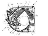
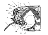
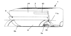
図1は本実施形態のセパレート型空気調和機の室内ユニットにおける導風パネルの覆い姿勢を示す断面図、図2は同じくその斜視図である。図3は室内ユニットのカバーパネルの開姿勢を示す断面図、図4は同じくその斜視図である。図5は室内ユニットにおける導風パネルの導風姿勢を示す断面図、図6は同じくその斜視図である。図7は室内ユニットを下側から見た斜視図、図8は吹出口の導風パネルおよびケーシングの前面パネルを取り除いた状態を示す斜視図である。
<First Embodiment>
FIG. 1 is a sectional view showing a covering posture of a wind guide panel in an indoor unit of a separate type air conditioner of the present embodiment, and FIG. 2 is a perspective view of the same. FIG. 3 is a sectional view showing the open posture of the cover panel of the indoor unit, and FIG. 4 is a perspective view of the same. FIG. 5 is a sectional view showing a wind guide posture of the wind guide panel in the indoor unit, and FIG. 6 is a perspective view of the same. FIG. 7 is a perspective view of the indoor unit as seen from below, and FIG. 8 is a perspective view showing a state in which the air guide panel of the air outlet and the front panel of the casing are removed.
室内ユニット1は、図1及び図2に示すように、ケーシング2の上面に空気の吸込口3が形成され、ケーシング2の前面下部に空気の吹出口4が形成される。ケーシング2の内部には、吸込口3から吹出口4に至る内部空気通路が形成され、この内部空気通路に熱交換器5と室内ファン6とが配設される。
As shown in FIGS. 1 and 2, the
内部空気通路は、ケーシング上面の吸込口3から吸込んだ室内の空気をフィルタを通した後、熱交換器5で熱交換し、冷風又は温風として室内ファン6によって吹出口4から室内側に放出されるものである。この内部空気通路において、吹出口近傍で正負のイオンを放出し、この正負の除菌イオンを吹出される空気と共に室内に放出されるように、イオン発生装置45を吹出口4の近傍に設けることができる。
In the internal air passage, after the indoor air sucked from the
室内ファン6は、クロスフローファンであって、その回転軸の軸方向が左右方向とされる。室内ファン6は、内部空気通路において熱交換器5よりも吹出口4側に配置される。
The indoor fan 6 is a crossflow fan, and the axial direction of the rotation axis is the left-right direction. The indoor fan 6 is disposed closer to the
熱交換器5は、4つの熱交換器5a〜5dから構成され、これらのうち3つの熱交換器5a、5b、5cが前後および上側の三方から室内ファン6を囲むように配置される。後側に位置する熱交換器5cの背面側には、さらに一つの補助熱交換器5dが後ろ側熱交換器5cと平行に配置される。各熱交換器5は、熱媒管と多数のフィンとから直方体形状に形成され、熱媒管の端部同士で他の熱交換器と接続され、冷凍サイクルの一部を構成するようになっている。
The heat exchanger 5 includes four
また、例えば、後ろ側の熱交換器5c、5dと前側の熱交換器5a、5bとの間に切換弁(不図示)を設け、除湿運転時には、後ろ側の熱交換器5c、5bを凝縮器として使用し、前側の熱交換器5a,5bで湿気を除去した空気を、後ろ側熱交換器5c、5dの排熱を利用して暖めて吹出口4から放出する再熱除湿もできるようになっている。
Also, for example, a switching valve (not shown) is provided between the
吸込口3に対面して吸込んだ室内の空気から塵埃を除去するフィルタ21が設けられる。フィルタ21は、極細繊維がネット状に編成又は織成され、吸込口3に対面して配置することにより、吸引した空気から塵や埃を除去できるようになっている。
A
このフィルタ21を清掃する清掃装置22が設けられる。フィルタ清掃装置22は、ケーシング2の上面前側と前面上側と前側の熱交換器5a、5bとで囲まれた空間部に配置される。フィルタ清掃装置22は、ケーシング2内でフィルタ21を移動させる側面視でU字形に湾曲した移動案内路24と、該移動案内路24に面してフィルタに付着した塵埃を吸引除去する塵埃除去ボックス25と、フィルタ21を移動案内路24に沿って移動させる駆動手段26とを備えている。
A
移動案内路24は、吸込口3に対面した配置されたフィルタ21の前端部をケーシング2の前部でU字状に折り返して熱交換器5側に導く経路となっている。そして、移動案内路24は、フィルタ4の左右両端部を挿入可能となっている。
The
塵埃除去ボックス25は、U字状の移動案内路24の上側通路部分に配置される。塵埃除去ボックス25は、断面半筒状の表側ボックス27と同じく断面半筒状の裏側ボックス28とが互いの開口を突き合せるように対向配置され、その間にフィルタ21を通過させるようになっている。表裏のボックス27,28の端部には吸引ファン(不図示)が設けられ、この吸引ファンにより、フィルタ21と略平行方向(左右方向)に空気を流すことで、フィルタ21に付着した塵埃を除去する。この際、塵埃除去ボックス内に回転ブラシを設け、フィルタ21に付着した塵埃を掻き取るようにしてもよい。
The
駆動手段26は、モータ30と、このモータ30に連結されたギヤ機構31等から構成される。最終のピニオンギヤが、フィルタ21の左右方向の端部に形成されたラック部に噛合され、モータ30を駆動することにより、フィルタ21が移動案内路24を往復動するようになっている。なお、フィルタ21の移動をスムーズに行うために、フィルタ21の一部を押圧するゴムローラを設けてもよい。
The drive means 26 includes a
また、ケーシング2の前面上部にはフィルタ21を着脱自在に挿入するフィルタ挿入口33が形成される。このフィルタ挿入口33は、U字形の移動案内路24の湾曲部に連通され、フィルタ21をフィルタ挿入口33から移動案内路24に着脱自在に介入できるようになっている。フィルタ挿入口33は、吹出口4の上側に形成された矩形の開口であって、左右一対のフィルタに合わせて左右一対の開口が設けられている。このフィルタ挿入口33を含み、ケーシング2の吹出口4よりも上側前面部は、前面パネル44によって覆われる。前面パネル44は、ケーシング2に対して着脱自在に取り付けられる。
In addition, a
吹出口4には、縦ルーバ36aと横ルーバ36bとからなる風向変更装置36が設けられ、吹出口4から吹出す風の向きを変更することができるようになっている。この風向変更装置36は、公知の構造のものである。本発明では、この風向変更装置36とは別に、ケーシング2の前面に覆い姿勢と導風姿勢に切換え自在な導風パネル7が設けられる。この導風パネル7は、吹出口4から吹出す空気を略水平方向で遠方に導くもので、導風パネル7の下端が第1の回動軸10周りに回動自在にケーシング2に軸支されている。
The
そして、導風パネル7は、第1の回動軸10周りに回動により、吹出口4から略水平方向に配置されて吹出口4から吹出す空気を略水平方向に導く導風姿勢と、ケーシング2の前面に沿って配置され、吹出口4を含むケーシングの前面の少なくとも下半分を覆う覆い姿勢とに切換え自在とされる。
And the
導風パネル7の導風姿勢は、主として、冷房運転時に吹出口4から吹出された風を導風パネル7に沿って略水平方向ないし斜め上方に導き、室内の天井に沿って遠方に空気に導くときに採用される。
The wind guide posture of the
また、導風パネル7は、その覆い姿勢で、ケーシング2の前面下部から前面にかけて、吹出口4及びその周辺部分を被覆するように設置される。すなわち、導風パネル7は、吹出口4よりも大きく形成されており、ケーシング2の前面のほぼ全域を覆う大きさとされている。
Moreover, the
さらに、導風パネル7は、主に吹出口4を覆うカバーパネル8と、該カバーパネル8の先端部に連続して設けられた延長パネル9とに分割される。カバーパネル8は延長パネル9に対して第2の回動軸11の周りに開閉回動自在に支持される。そして、カバーパネル8は、延長パネル9をケーシング2の前面に沿わせた覆い姿勢を保ちつつ、第2の回動軸11の周りの回動により、吹出口4を覆う閉姿勢と、下端が垂直方向に開いた開姿勢とに切り換え自在とされる。カバーパネル8の開姿勢は、主として暖房運転時や局所的に冷風を吹出させたい急速冷房運転時に、吹出口4から吹出した風を垂直下方に導くときに採用される。
Further, the
また、導風パネル7では、吹出口4の背面側の湾曲した通路壁に連続して風を遠方に導くことができるように、カバーパネル8が側面視で凹曲面形状に形成され、逆に、延長パネル9では、カバーパネル8から導かれた風がケーシング上面の吸込口3に吸込まれてショートサーキットを起こさないように内側に凸曲面形状に形成される。
Further, in the
また、カバーパネル8および延長パネル9は、吹出口4から導かれる冷風と室内の空気との接触により導風パネル7の表側に結露するのを防止するため、その内側が断熱ポリウレタンフォームで成形される。
Further, the cover panel 8 and the
導風パネル7の回動機構について、さらに詳述する。延長パネル9は、吹出口4の左右外側位置で左右一対の脚部9bが垂設される。脚部9bの下端部は、ケーシング2に第1の回動軸10周りに回動自在に軸支される。
The rotation mechanism of the
また、導風パネル7を構成する延長パネル9の左右両端部には、回動アーム16が取り付けられている。回動アーム16には第1の回動軸10を中心として円弧状に湾曲するラック16aが形成されている。ラック16aは、ケーシング2内に設置されているピニオン(図示略)と噛合しており、ピニオンが駆動することによって延長パネル9が回動軸線10a周りに回動する。導風パネル7が吹出口4を開放する際には、カバーパネル8は通気部9aを塞ぐ姿勢のままで延長パネル9とともに一体的に回動軸線10a周りに回動する。これにより、延長パネル9は、ケーシング2に沿って配される覆い姿勢と略水平方向に位置する導風姿勢とに切換え回動自在とされる。
In addition, turning
また、脚部9bは、板状であってケーシング2に沿って湾曲形状に形成される。また、一対の脚部9b間には吹出口4とほぼ同じ大きさの通気部9aが形成される。
The
一方、カバーパネル8は、ケーシング2の左右幅とほぼ同じ左右幅を有する。従って、延長パネル9の脚部9bを覆い隠すように配置される。このカバーパネル8の上端は、延長パネル9に設けられた第2の回動軸11の軸線11a周りに回動自在に取り付けられる。
On the other hand, the cover panel 8 has a lateral width that is substantially the same as the lateral width of the
さらに、詳述すると、カバーパネル8の左右両端部にはケーシング2の左右方向と平行に第2の回動軸11が形成される。第2の回動軸11は、延長パネル9の脚部9bに形成された軸受部に回動自在に軸受けされる。この軸受部は、吹出口4上端よりも上方位置に配置される。
More specifically, the second
また、カバーパネル8には、第2の回動軸11を中心として扇状ギヤ15が設けられる。そして、延長パネル9がケーシング2に接近した覆い姿勢で、扇状ギヤ15がケーシング内に設置された駆動ギヤに噛合する。そして、駆動ギヤの回転駆動動作により、これに噛合う扇状ギヤ15が回転し、カバーパネル8が回動するようになっている。
In addition, the cover panel 8 is provided with a fan-shaped gear 15 around the
また、カバーパネル8には、回動軸線11aを挟んで反対側にシール部12が形成される。このシール部12に対向して、ケーシングの吹出口4の上方位置でケーシング左右幅方向Aに溝部19が形成される。溝部19は、カバーパネル8が延長パネル9に対して下端を開放した開姿勢をとるとき、シール部12がケーシング2に接近する方向に回動するのを許容するために形成される。そして、溝部19の下壁部がシール部12と当接する。
Further, the cover panel 8 is formed with a
延長パネル9には、シール部12と延長パネル9との間の隙間をシールするシール材17が配設される。また、ケーシング2の吹出口4の下縁には、導風パネル7とケーシング2との間の隙間をシールするシール材18が配設される。
The
また、ケーシング2の前面上部には、運転表示部40とリモコンの第1の受信部41が並んで配設される。運転表示部40および第1の受信部41の配置は、導風パネル7の覆い姿勢で、導風パネル7の上端よりも上側に位置する。また、ケーシング2の下面で、吹出口4および導風パネル7から外れた位置に、第1の受信部41とは別に第2の受信部42が配設される。
In addition, an
運転表示部40では、LEDにより、除菌イオンの運転状況や室内の空気の汚れ具合を表示する。また、設定温度や室外の温度を表示する。第1受信部41および第2の受信部42では、リモコンからの赤外線信号を受信する。
The
上記構成においては、運転停止時には、導風パネル7がケーシング2の前面に沿ってケーシング2のほぼ全面に配置された状態となっているが、導風パネル7よりも上方に運転表示部40があるため、室内空気の汚れ具合の表示や温度表示を容易に視認することができ、その視認結果に基づき空気調和機の運転制御を行いやすくなる。
In the above configuration, when the operation is stopped, the
また、冷房運転時に導風パネル7を第1の回動軸10周りに回動して導風姿勢にすると、吹出口4から吹出した空気は、略水平方向の導風パネル7により遠方へ導かれ、略水平方向ないし斜め上方へ遠方まで飛ばすことができる。したがって、室内ユニットを天井近くの壁面に据え付けた場合、吹出口4から吹出した冷風は天井面に沿って室内全体に行き渡り、室内全体を冷房することができる。
In addition, when the
このとき、運転表示部40は、ケーシング2の前面上部に位置し、吹出口4の近傍から離れた場所に設置されているので、吹出口4から吹出す冷風により運転表示部40が結露するのを防止することができる。
At this time, since the
また、導風パネル7は、その導風姿勢で、略水平方向に張り出し、また、導風パネル自体の左右幅もケーシング幅と同じであるため、ケーシングの上部前面に位置する第1の受信部41ではリモコンからの送信を受信することができない。しかし、ケーシング2の下面に第2の受信部42を設けているので、リモコンからの指示信号を容易に受信することができ、遠隔制御操作も容易に行える。
Further, the
一方、暖房運転時などに、カバーパネル8を第2の回動軸11周りに開回動すると、カバーパネル8が垂直方向に向き、吹出口4から吹出した風が下方に導かれる。このとき、室内ユニットから離れた位置でリモコンを操作した場合、カバーパネル8の垂直姿勢で下方に垂れ下がった状態となり、リモコンからの操作信号がカバーパネル8によって遮断され、ケーシング2の下面の第2の受信部42では受信できない可能性があるが、上側の第1の受信部41で受信することができるので、遠隔操作を容易に行なうことができる。
On the other hand, when the cover panel 8 is opened and rotated around the
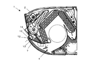
<第2の実施形態>
図9及び図10は、本発明の第2実施形態を示すセパレート型空気調和機の室内ユニットの断面図である。図9は吹出口を覆うカバーパネルの閉姿勢を示し、図10は同じくカバーパネルの開姿勢を示す。
<Second Embodiment>
9 and 10 are cross-sectional views of an indoor unit of a separate type air conditioner showing a second embodiment of the present invention. FIG. 9 shows the closed posture of the cover panel covering the outlet, and FIG. 10 shows the open posture of the cover panel.
本実施形態における室内ユニット1は、ケーシング2の前面下部に形成された吹出口4を覆う導風パネルを備え、該導風パネル7は、その上端に回動軸10が形成されており、ケーシング2の吹出口4上端よりも上方位置で回動軸10を受ける軸受部に回動自在に軸支されている。
The
導風パネル7は、吹出口4を覆う覆い姿勢と、覆い姿勢からの回動角度が最も大きく略水平ないしそれよりも斜め上方に開放した導風姿勢と、両姿勢の中間で吹出口4から吹出した空気を下方に導く垂直姿勢との間で回動切換え自在とされる。
The
運転表示部並びに第1の受信部および第2の受信部の配置位置は第1の実施形態と同様である。 The arrangement positions of the operation display unit, the first receiving unit, and the second receiving unit are the same as those in the first embodiment.
上記構成においては、導風パネル7を覆い姿勢、導風姿勢、垂直姿勢のいずれの姿勢としたときも運転表示部40を視認することができる。また、リモコンからの信号は、仮に、導風パネル7が導風姿勢のときに、導風パネル7によりリモコンの信号が遮断され、第1の受信部41に届かなくても、ケーシングの下面にある第2の受信部42により受信することができるので、空気調和機の遠隔制御も容易に行うことができる。
In the above configuration, the
なお、本発明は、上記実施形態に限定されるものではなく、本発明の範囲内で多くの修正・変更を加えることができるのは勿論である。 Note that the present invention is not limited to the above-described embodiment, and it is needless to say that many modifications and changes can be made within the scope of the present invention.
1 室内ユニット
2 ケーシング
3 吸込口
4 吹出口
5 熱交換器
6 室内ファン
7 導風パネル
8 カバーパネル
9 延長パネル
9a 通気部
9b 脚部
10 第1回動軸
11 第2回動軸
21 フィルタ
22 フィルタ清掃装置
24 移動案内路
25 塵埃除去ボックス
26 駆動手段
27 表側ボックス
28 裏側ボックス
30 モータ
31 ギヤ機構
33 フィルタ挿入口
40 運転表示部
41 第1の受信部
42 第2の受信部
A ケーシング左右方向
DESCRIPTION OF
Claims (3)
Priority Applications (1)
| Application Number | Priority Date | Filing Date | Title |
|---|---|---|---|
| JP2006314759A JP4847299B2 (en) | 2006-11-21 | 2006-11-21 | Air conditioner |
Applications Claiming Priority (1)
| Application Number | Priority Date | Filing Date | Title |
|---|---|---|---|
| JP2006314759A JP4847299B2 (en) | 2006-11-21 | 2006-11-21 | Air conditioner |
Publications (3)
| Publication Number | Publication Date |
|---|---|
| JP2008128572A JP2008128572A (en) | 2008-06-05 |
| JP2008128572A5 JP2008128572A5 (en) | 2009-05-14 |
| JP4847299B2 true JP4847299B2 (en) | 2011-12-28 |
Family
ID=39554579
Family Applications (1)
| Application Number | Title | Priority Date | Filing Date |
|---|---|---|---|
| JP2006314759A Active JP4847299B2 (en) | 2006-11-21 | 2006-11-21 | Air conditioner |
Country Status (1)
| Country | Link |
|---|---|
| JP (1) | JP4847299B2 (en) |
Families Citing this family (3)
| Publication number | Priority date | Publication date | Assignee | Title |
|---|---|---|---|---|
| CN107655192B (en) * | 2017-08-14 | 2023-05-23 | 奥克斯空调股份有限公司 | Base structure of indoor unit of air conditioner and indoor unit of base structure |
| CN108088060B (en) * | 2018-01-04 | 2023-08-11 | 奥克斯空调股份有限公司 | Air conditioner air guide system and air conditioner |
| CN113865070B (en) * | 2021-11-01 | 2023-08-18 | 青岛海尔空调器有限总公司 | Wall-mounted air conditioner indoor unit |
Family Cites Families (10)
| Publication number | Priority date | Publication date | Assignee | Title |
|---|---|---|---|---|
| JPS6146319A (en) * | 1984-08-09 | 1986-03-06 | Mitsubishi Heavy Ind Ltd | Elongation percentage control device |
| JPH01282933A (en) * | 1988-05-09 | 1989-11-14 | Sanyo Electric Co Ltd | System and apparatus for receiving infrared-ray signal |
| JPH11159841A (en) * | 1997-11-28 | 1999-06-15 | Mitsubishi Heavy Ind Ltd | Air conditioner |
| JPH11220427A (en) * | 1998-01-30 | 1999-08-10 | Nec Corp | Remote control receiver and remote control system |
| JP3619406B2 (en) * | 1999-10-14 | 2005-02-09 | シャープ株式会社 | Air conditioner |
| MY129452A (en) * | 1999-11-30 | 2007-04-30 | Matsushita Air Conditioning R & D Ct Sdn Bhd | Air conditioning system and air conditioning method |
| JP2001349601A (en) * | 2000-06-06 | 2001-12-21 | Fujitsu General Ltd | Air conditioner |
| JP2002061933A (en) * | 2000-08-17 | 2002-02-28 | Hitachi Ltd | Air conditioner |
| JP2002349945A (en) * | 2001-05-30 | 2002-12-04 | Daikin Ind Ltd | Air conditioner |
| JP2007278602A (en) * | 2006-04-07 | 2007-10-25 | Matsushita Electric Ind Co Ltd | Air conditioner |
-
2006
- 2006-11-21 JP JP2006314759A patent/JP4847299B2/en active Active
Also Published As
| Publication number | Publication date |
|---|---|
| JP2008128572A (en) | 2008-06-05 |
Similar Documents
| Publication | Publication Date | Title |
|---|---|---|
| WO2010021383A1 (en) | Indoor machine of air conditioner | |
| JP2007155309A (en) | Indoor panel for air conditioner and air conditioner | |
| JP2008128622A (en) | Air conditioner | |
| CN106440304A (en) | Air conditioner air inlet dustproof mechanism and air conditioner | |
| JP2008138892A (en) | Air conditioner | |
| JP5409202B2 (en) | Air conditioner indoor unit | |
| CN101839524A (en) | Air conditioner | |
| JP4847299B2 (en) | Air conditioner | |
| JP7332341B2 (en) | air conditioner | |
| JP5375900B2 (en) | Air conditioning indoor unit | |
| JP2007303771A (en) | Air conditioner | |
| JP2008111593A (en) | Air conditioner | |
| JP2010048491A (en) | Indoor unit for air conditioner | |
| JP2010286194A (en) | Indoor unit for air conditioner | |
| JP5386509B2 (en) | Air conditioner indoor unit | |
| KR100867953B1 (en) | Air-conditioner | |
| JP2008133969A (en) | Air conditioner | |
| JP4580378B2 (en) | Air conditioner | |
| JP6079963B2 (en) | Air conditioner and control circuit | |
| JP2012042182A (en) | Indoor unit of air conditioner | |
| JP2010112600A (en) | Indoor unit for air conditioning system and air conditioning system provided with the same | |
| KR101450562B1 (en) | Air conditioner | |
| JP4814067B2 (en) | Air conditioner | |
| JP2006226562A (en) | Indoor unit for air conditioner, and control method of indoor unit of air conditioner | |
| JP7233300B2 (en) | air conditioner |
Legal Events
| Date | Code | Title | Description |
|---|---|---|---|
| A521 | Request for written amendment filed |
Free format text: JAPANESE INTERMEDIATE CODE: A523 Effective date: 20090327 |
|
| A621 | Written request for application examination |
Free format text: JAPANESE INTERMEDIATE CODE: A621 Effective date: 20090327 |
|
| A977 | Report on retrieval |
Free format text: JAPANESE INTERMEDIATE CODE: A971007 Effective date: 20110120 |
|
| A131 | Notification of reasons for refusal |
Free format text: JAPANESE INTERMEDIATE CODE: A131 Effective date: 20110125 |
|
| TRDD | Decision of grant or rejection written | ||
| A01 | Written decision to grant a patent or to grant a registration (utility model) |
Free format text: JAPANESE INTERMEDIATE CODE: A01 Effective date: 20110920 |
|
| A01 | Written decision to grant a patent or to grant a registration (utility model) |
Free format text: JAPANESE INTERMEDIATE CODE: A01 |
|
| A61 | First payment of annual fees (during grant procedure) |
Free format text: JAPANESE INTERMEDIATE CODE: A61 Effective date: 20111013 |
|
| FPAY | Renewal fee payment (event date is renewal date of database) |
Free format text: PAYMENT UNTIL: 20141021 Year of fee payment: 3 |
|
| R150 | Certificate of patent or registration of utility model |
Ref document number: 4847299 Country of ref document: JP Free format text: JAPANESE INTERMEDIATE CODE: R150 Free format text: JAPANESE INTERMEDIATE CODE: R150 |