JP4846971B2 - Filtration device having calendared leukocyte removal layer and bag system having the filtration device - Google Patents
Filtration device having calendared leukocyte removal layer and bag system having the filtration device Download PDFInfo
- Publication number
- JP4846971B2 JP4846971B2 JP2003033803A JP2003033803A JP4846971B2 JP 4846971 B2 JP4846971 B2 JP 4846971B2 JP 2003033803 A JP2003033803 A JP 2003033803A JP 2003033803 A JP2003033803 A JP 2003033803A JP 4846971 B2 JP4846971 B2 JP 4846971B2
- Authority
- JP
- Japan
- Prior art keywords
- filtration device
- layer
- bag
- filtration
- porous element
- Prior art date
- Legal status (The legal status is an assumption and is not a legal conclusion. Google has not performed a legal analysis and makes no representation as to the accuracy of the status listed.)
- Expired - Fee Related
Links
Images


Classifications
-
- A—HUMAN NECESSITIES
- A61—MEDICAL OR VETERINARY SCIENCE; HYGIENE
- A61M—DEVICES FOR INTRODUCING MEDIA INTO, OR ONTO, THE BODY; DEVICES FOR TRANSDUCING BODY MEDIA OR FOR TAKING MEDIA FROM THE BODY; DEVICES FOR PRODUCING OR ENDING SLEEP OR STUPOR
- A61M5/00—Devices for bringing media into the body in a subcutaneous, intra-vascular or intramuscular way; Accessories therefor, e.g. filling or cleaning devices, arm-rests
- A61M5/14—Infusion devices, e.g. infusing by gravity; Blood infusion; Accessories therefor
- A61M5/165—Filtering accessories, e.g. blood filters, filters for infusion liquids
-
- A—HUMAN NECESSITIES
- A61—MEDICAL OR VETERINARY SCIENCE; HYGIENE
- A61M—DEVICES FOR INTRODUCING MEDIA INTO, OR ONTO, THE BODY; DEVICES FOR TRANSDUCING BODY MEDIA OR FOR TAKING MEDIA FROM THE BODY; DEVICES FOR PRODUCING OR ENDING SLEEP OR STUPOR
- A61M1/00—Suction or pumping devices for medical purposes; Devices for carrying-off, for treatment of, or for carrying-over, body-liquids; Drainage systems
- A61M1/02—Blood transfusion apparatus
- A61M1/0209—Multiple bag systems for separating or storing blood components
- A61M1/0218—Multiple bag systems for separating or storing blood components with filters
-
- A—HUMAN NECESSITIES
- A61—MEDICAL OR VETERINARY SCIENCE; HYGIENE
- A61M—DEVICES FOR INTRODUCING MEDIA INTO, OR ONTO, THE BODY; DEVICES FOR TRANSDUCING BODY MEDIA OR FOR TAKING MEDIA FROM THE BODY; DEVICES FOR PRODUCING OR ENDING SLEEP OR STUPOR
- A61M1/00—Suction or pumping devices for medical purposes; Devices for carrying-off, for treatment of, or for carrying-over, body-liquids; Drainage systems
- A61M1/02—Blood transfusion apparatus
- A61M1/0281—Apparatus for treatment of blood or blood constituents prior to transfusion, e.g. washing, filtering or thawing
-
- A—HUMAN NECESSITIES
- A61—MEDICAL OR VETERINARY SCIENCE; HYGIENE
- A61M—DEVICES FOR INTRODUCING MEDIA INTO, OR ONTO, THE BODY; DEVICES FOR TRANSDUCING BODY MEDIA OR FOR TAKING MEDIA FROM THE BODY; DEVICES FOR PRODUCING OR ENDING SLEEP OR STUPOR
- A61M1/00—Suction or pumping devices for medical purposes; Devices for carrying-off, for treatment of, or for carrying-over, body-liquids; Drainage systems
- A61M1/36—Other treatment of blood in a by-pass of the natural circulatory system, e.g. temperature adaptation, irradiation ; Extra-corporeal blood circuits
- A61M1/3621—Extra-corporeal blood circuits
- A61M1/3627—Degassing devices; Buffer reservoirs; Drip chambers; Blood filters
- A61M1/3633—Blood component filters, e.g. leukocyte filters
- A61M1/3635—Constructional details
- A61M1/3636—Constructional details having a flexible housing
-
- B—PERFORMING OPERATIONS; TRANSPORTING
- B01—PHYSICAL OR CHEMICAL PROCESSES OR APPARATUS IN GENERAL
- B01D—SEPARATION
- B01D15/00—Separating processes involving the treatment of liquids with solid sorbents; Apparatus therefor
-
- B—PERFORMING OPERATIONS; TRANSPORTING
- B01—PHYSICAL OR CHEMICAL PROCESSES OR APPARATUS IN GENERAL
- B01D—SEPARATION
- B01D39/00—Filtering material for liquid or gaseous fluids
- B01D39/14—Other self-supporting filtering material ; Other filtering material
- B01D39/16—Other self-supporting filtering material ; Other filtering material of organic material, e.g. synthetic fibres
Abstract
Description
【0001】
【発明の属する技術分野】
本発明は、液体から白血球を除去する濾過装置に関し、さらにそのような濾過装置を有する、バッグを基礎としたシステム(bag-based system、以下バッグシステムと称する)に関する。
【0002】
このバッグシステムは典型的には、そのバッグシステム、特に閉路において血液又は血液成分を濾過することと、血液を異なる成分に分離し捕集することとに適用される。
【0003】
【従来の技術】
濾過装置は、少なくとも1つの入口穴及び少なくとも1つの出口穴を備えた外側ケーシングを有するものとして既知である。濾過されるべき液体はそれらの穴の間をある方向に流れ、ケーシングは、白血球の吸着及び濾過によって白血球を除去するための手段を備えた多孔性の要素を有する。
【0004】
例えばEP−A−0526678号に例示されたそのような装置においては、多孔性の不織材料から形成された積層フィルターを白血球の除去手段として使用することは一般的である。
【0005】
従って、この種の濾過(深層濾過として知られる)において、白血球を保持するための濾過手段の能力は、特に液体が通過する材料の量、故に濾過手段の厚さの関数である。さらに、複数の微細な層を配置することにより、1つの層から形成された同じ厚さの濾過手段に比べて白血球除去効率が改善される。
【0006】
従ってこの種の濾過の有効性を改善すること、すなわち白血球除去手段により保持される白血球の量を増加させるためには、積み重ねられる層の数を増やすことが考えられる。
【0007】
【特許文献1】
EP−A−0526678号
【0008】
【発明が解決しようとする課題】
しかしこの解決策はいくつかの欠点を有する。
【0009】
第1に、この解決策はフィルターの全体の寸法を増加させ、これは一般的に言って望ましくない。さらに、この解決策は濾過装置の死容積(dead volume)、すなわち濾過後に濾過装置内に残る液体の量を増加させる。この液体は最終的には損失となるか、或いは回収困難である。特に、少量の液体を濾過する目的の濾過装置においては、この制約は急速な妨げとなる。
【0010】
次に、多数の層によって、白血球除去手段を重力により通過する液体の流速はかなり減ぜられ、故に濾過時間はそれに応じて増加する。
【0011】
さらに本願出願人は、濾過時間を増加させても、ある値以上になると、白血球除去手段によって保持された白血球の量に対して顕著に良い影響は与えないことを見出した。
【0012】
従って本発明の目的は、濾過流速に不都合な影響を与えることなく、改良された適当な濾過能力を有する装置を提供することによって、これらの欠点を排除することである。さらにこの濾過装置は、バッグシステム内の特に閉路に組み入れることができ、血液の異なる成分の分離及び捕集を単純な方法で行うことを可能にする。
【0013】
【課題を解決するための手段】
その目的のために本発明は、本発明の第1の形態に従って、血液又は血液成分のような液体からの白血球の除去を可能にするための濾過装置であって、少なくとも1つの入口穴及び少なくとも1つの出口穴を備えた外側ケーシングを有し、濾過されるべき液体は入口穴と出口穴との間をある方向に流れ、ケーシングは、白血球の吸着及び濾過によって白血球を除去するための手段を備えた多孔性要素を有し、その手段は、少なくとも1つの多孔性の不織材料から形成されたものと全く同一の種類の材料の複数の層を有する、濾過装置において、少なくとも1つの層は、積み重ねられる前にカレンダー加工によって押圧され、そのカレンダー加工された少なくとも1つの層は、積み重ねられた層の下流側に配置され、一方、白血球除去手段は少なくとも1つのカレンダー加工されていない層を有する、濾過装置を提供する。
【0014】
本発明は、本発明の第2の形態に従って、血液又は血液成分のような液体から白血球を除去するためのバッグシステムを提供する。このバッグシステムは、濾液を捕集するためのバッグを有し、このバッグは、その入口穴においてチューブ手段を用いて、上述した濾過装置の出口穴に接続される。
【0015】
本発明の他の目的及び長所は、添付図面を参照しながら行われる以下の説明によって明らかになるであろう。
【0016】
【発明の実施の形態】
図1及び図2は、血液又は血液成分のような液体からの白血球の除去を可能にする濾過装置1を示す。血液成分とは特に、赤血球、血漿又は血小板を意味し、赤血球及び血小板は可能な限り濃縮されること及び懸濁液中に分散されることの少なくとも一方がなされ、血漿は血小板を可能な限り少なく又は多く有する。
【0017】
捕集された後の血液、又は捕集され分離された後の血液成分は、特にそれを必要とする患者に輸血される。この輸血が行われている間は、白血球は、有害な反応又は潜在的に危険な反応(あるいはその双方)を患者に生じさせやすいことから、望ましくないことがよく知られている。
【0018】
この理由により、ある国では実際に定められていることであるが、血液又は血液成分を輸血する前にそこから白血球を除去することが推奨されている。現在までのところ、白血球を除去する最適な方法は、血液又は血液成分を、白血球除去手段を有する濾過装置を通して濾過することである。
【0019】
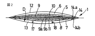
図1及び図2に示す実施形態においては、濾過装置1は外側ケーシング2を有する。外側ケーシング2は、濾過されるべき液体を受け入れるための入口穴3、及び濾液を捕集するための出口穴4を備える。濾過されるべき液体は、それらの穴の間をDの方向に流れる。
【0020】
装置1はまた、外側ケーシング2内に配置された多孔性要素5を有し、それにより入口穴3に連通する入口区画6、及び出口穴4に連通する出口区画7が形成される。
【0021】
本明細書における説明では、「入口」、「出口」、「上流」及び「下流」という用語は、濾過装置1における液体の移動方向に関して定義されるものとする(図1及び図2の矢印Dを参照のこと)。
【0022】
濾過装置1が入口穴3を用いて液体供給されると、液体は、入口区画6に満たされ、次に多孔性要素5を通過し、出口区画7内に捕集される。次に、出口穴4によって濾液が捕集可能となる。
【0023】
多孔性要素5は、白血球の吸着及び濾過によって白血球を除去するための手段8を有する。白血球除去手段8は、少なくとも1つの多孔性不織材料から形成された第1の種類の層9を複数有する。層の種類とは、実質的に同じ構成、空隙率及び物理化学的性質、すなわち実質的に同じ白血球保持能力を有する材料の層を意味する。
【0024】
ある実施形態によれば、液体の流れ方向Dについて白血球除去手段8の下流側に、複数の層9を積み重ねることができる。
【0025】
本発明によると、これらの層9の少なくとも1つ(全てではない)は、積み重ねられる前にカレンダー加工(特に冷間カレンダー加工)によって押圧され、カレンダー加工された層9aは積み重ねられた層の下流側に配置される。従って層の積層体は、上流から下流にかけて、少なくとも1つのカレンダー加工されない層9b及びカレンダー加工された層9aを有する。層9a及び9bは全て同じ種類である。
【0026】
この特定の実施形態により、白血球除去手段8が有する白血球の吸着及び濾過の能力は、カレンダー加工されない層の積層体に比べて改善可能である。カレンダー加工によって層の平均の空隙率及び空気透過率を下げることが可能になり、それにより層の白血球保持能力が上がるからである。本願出願人はさらに、本発明に係る白血球除去手段8の使用により、白血球の除去レベルを実質的に引き下げることなく、液体の採取とその液体の濾過との間の時間を増やすことができることを見出した。例えばこの時間が18時間であるときも、十分な白血球除去レベルが確保される。
【0027】
さらに、全てカレンダー加工された層の積層体と比べると、本発明によって白血球除去手段8の目詰まりの危険性が少なくなり、また流速の維持すなわち最適な濾過時間を保つことが可能になる。
【0028】
さらに本発明によれば、カレンダー加工された複数の層9aは、他の国の法制によって定められた又は所望の白血球除去効率に従って調節可能である。
【0029】
最後に、カレンダー加工された層9a又はカレンダー加工されない層9bは同じ種類であるため、本発明により提唱される解決策によって、非常に単純な積層体製品が既述の長所を有することが可能になる。
【0030】
図1及び図2に示す実施形態の変形例においては、白血球除去手段8は、少なくとも第2の種類の少なくとも1つの層を有する。その1つ又は複数の層は、第1の種類の複数の層9の上であって、その上流側又は下流側に積み重ねられる。
【0031】
特に、それらの層の種類は、それらの層を形成する材料の性質とそれらの層の物理化学的性質との少なくとも一方によって相異なることが可能である。
【0032】
ある実施形態によると、積み重ねられた層の平均の空隙率は、流れ方向に連続的又は不連続的に減少する。従って、白血球除去手段8の目詰まりの危険性を下げつつ、白血球除去効率を最適化することができる。
【0033】
多孔性要素5はまた、白血球除去手段8の上流側及び下流側にそれぞれ配置される前フィルター10及び後フィルター11の少なくとも一方を有することができる。前フィルター10及び後フィルター11の少なくとも一方は、少なくとも1つの不織材料の層から形成可能である。
【0034】
第1の実施形態によると、複数の層9を形成する材料は親水性であり、特にセルロース又はその派生物(例えばセルロースアセテート)から作製される。
【0035】
第2の実施形態によると、複数の層9を形成する材料は、ポリプロピレン、ポリエステル、ポリアミド、高密度又は低密度ポリエチレン、ポリウレタン、ポリフッ化ビニリデン、ポリビニルピロリドン及びそれらの派生物を基材とするポリマー又はコポリマーを含むグループから選択される。
【0036】
本来これらのポリマー製品は一般に親水性ではないので、物理的方法及び化学的方法の少なくとも一方によって処理され、親水性を有する必要がある。
【0037】
これらの処理には、例えばヒドロキシル基又はカルボキシル基のような親水性置換基を、既知の方法に従ってポリマーに例えば移植すること(grafting)が含まれる。
【0038】
物理的方法及び化学的方法の少なくとも一方によって親水性を有するそのようなポリマーは、市販されている。
【0039】
図1及び図2に関連して、濾過装置1のある実施形態を以下に説明する。
【0040】
図示された実施形態においては、外側ケーシング2は、可撓性を有し、可撓性プラスチック材料の2つのシート12及び13を組み立てることより形成される。2つのシート12及び13は、例えばそれらの周縁を溶着することによって互いに組み立てられる。
【0041】
多孔性要素5は、可撓性フレーム14から形成された変形可能な不浸透性の関連付け手段によって外側ケーシング2内に保持される。
【0042】
可撓性フレーム14は、例えば可塑化した2つのシート14a及び14bの組体により形成され、多孔性要素5は2つのシート14a及び14bの間に配置される。
【0043】
これらの2つのシート14a及び14bは、その中央部にて穿孔され、各々が少なくとも1つの開口部15を有し、それにより濾過されるべき液体の通路が提供される。
【0044】
2つのシート14a及び14bは、好ましくは多孔性要素5の周縁領域内において、例えば溶着シーム16によって互いに固定される。溶着シーム16は、多孔性要素5を通って形成され、多孔性要素5を固定して封着する。
【0045】
多孔性要素5を通ってシート14a及び14bを溶着することにより、多孔性要素5の周りが圧縮され、多孔性要素5の周りに不浸透性のシームが形成される。
【0046】
可撓性フレーム14は、その周縁において、外側ケーシング2を形成する外側のシート12及び13とともに溶着される。これらはその全周囲に渡りかつそれらの周縁領域内で互いに溶着されるため、シールが形成される。
【0047】
この溶着が行われるときは、チューブの一部から形成された入口穴3が可撓性フレーム14の一方の側に配置され、チューブの他の一部から形成された出口穴4が可撓性フレーム14の他方の側に配置される。
【0048】
従って、一方のシート12と多孔性要素5との間に形成された入口区画6は入口穴3に連通し、他方のシート13と多孔性要素5との間に形成された出口区画7は入口穴4に連通する。
【0049】
多孔性要素5が外側ケーシング2に張り付いて液体の流れが妨害されることを防ぐために、出口区画7の内側であって多孔性要素5と外側ケーシング2との間に、2つのスペースロッド17及び18が配置される。
【0050】
これらの2つのスペースロッド17及び18によって出口区画7は多孔性要素5から離れて維持されるため、多孔性要素5が外側のシート13の内壁に張り付くことが防止される。
【0051】
スペースロッド17及び18は可撓性チューブから作製可能である。可撓性チューブは、例えば外側ケーシング2のシートの内壁において、例えば周縁溶着された領域内で溶着される。
【0052】
スペースロッド17及び18の個数は、例えば濾過装置1の寸法によって変更可能であることは明らかである。
【0053】
例えば、外側区画7の内側にループを形成するように曲げられる1つのスペースロッドを用意することも予見可能である。
【0054】
可撓性のスペースロッド17及び18は、濾過装置1の曲げに支障がないように使用されることが好ましい。
【0055】
他の実施形態(図示せず)においては、外側ケーシング2は剛性であり、例えばポリカーボネートのような剛性のプラスチック材料から作製される。
【0056】
本発明に係る濾過装置1のための多孔性要素5の2つの例示的実施形態を以下に説明する。
【0057】
実施形態1
多孔性要素5は、上流から下流にかけて互いに積み重ねられる以下の層を有する。
− 各々の層が、400μmのオーダーの厚さe、35μmである平均空隙率p、及び1000l/m2/s〜5000l/m2/sである空気透過率Pを有する、ポリエステルから作製された不織材料の4つの層(前フィルター10)
− 各々の層が、250μm<e<400μm、8.5μm<p<10μm、及び130l/m2/s<P<200l/m2/sである、ポリプロピレンからメルトブローにより作製された不織材料の22個の層9b
− 各々の層が、個々にカレンダー加工されて、130μm<e<250μm、7μm<p<9μm、及び70l/m2/s<P<130l/m2/sとなる、上記の22個の層9bと同じ種類9のポリプロピレンからメルトブローにより作製された不織材料の2つの層9a
− 400μmのオーダーの厚さe、35μmである平均空隙率p、及び1000l/m2/s〜5000l/m2/sである空気透過率Pを有する、ポリエステルからメルトブローにより作製された不織材料の1つの層(後フィルター11)
【0058】
ある特定の実施形態においては、この多孔性要素5は、50〜58cm2(例えば55cm2)の濾過面を有する。それにより、450mlの液体の濾過について対数で4.8のレベル(すなわち多孔性要素5を通過する白血球の量は1/104.8になる)が可能になる。それに比べ、同様の死容積及び濾過時間であって、2つの層9aがカレンダー加工されていない類似の多孔性要素においては、対数で4.3である。
【0059】
勿論、達成すべき白血球除去目標に従って、異なる数の層9がカレンダー加工可能である。
【0060】
実施形態2
多孔性要素5は、上流から下流にかけて互いに積み重ねられる以下の層を有する。
− 各々の層が、400μmのオーダーの厚さe、35μmである平均空隙率p、及び1000l/m2/s〜5000l/m2/sである空気透過率Pを有する、ポリエステルから作製された不織材料の2つの層(前フィルター10)
− 各々の層が、250μm<e<400μm、10μm<p<20μm、及び250l/m2/s<P<400l/m2/sである、ポリプロピレンからメルトブローにより作製された不織材料の2つの層
− 各々の層が、250μm<e<400μm、8.5μm<p<10μm、及び130l/m2/s<P<200l/m2/sである、ポリプロピレンからメルトブローにより作製された不織材料の18個の層9b
− 各々の層が、個々にカレンダー加工されて、130μm<e<250μm、7μm<p<9μm、及び70l/m2/s<P<130l/m2/sとなる、上記の18個の層9bと同じ種類9のポリプロピレンからメルトブローにより作製された不織材料の2つの層9a
− 400μmのオーダーの厚さe、35μmである平均空隙率p、及び1000l/m2/s〜5000l/m2/sである空気透過率Pを有する、ポリエステルからメルトブローにより作製された不織材料の1つの層(後フィルター11)
【0061】
ある特定の実施形態においては、この多孔性要素5は、15〜35cm2(例えば20cm2)の濾過面を有する。それにより、200mlの液体の濾過が可能になる。
【0062】
図3及び図4に関連して、血液又は血液成分から白血球を除去するためのバッグシステムの第1の実施形態について以下に説明する。このバッグシステムは、濾液を捕集するための捕集バッグ19を有し、捕集バッグ19は、その入口穴21においてチューブ20を用いて、本発明に係る濾過装置1の出口穴4に接続される。
【0063】
このバッグシステムはまた、濾過されるべき液体を有するバッグへの接続手段22を有し、またそのバッグは、チューブ手段23によって濾過装置1の入口穴3に接続される。
【0064】
従って一度集められた液体は、バッグシステム内に導かれ、濾過装置1によって濾過される。その濾液は捕集バッグ19に捕集される。
【0065】
図4に示す変形例においては、微小凝集塊フィルター24が濾過装置1の上流にてバッグシステムに接続される。
【0066】
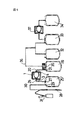
図5及び図6に関連して、血液又は血液成分のような液体から無菌かつ閉路にて白血球を除去するためのバッグシステムの第1及び第2の実施形態について以下に説明する。このバッグシステムは本発明に係る濾過装置を有する。
【0067】
この目的のために、バッグシステムは、濾過されるべき液体を収容するための蓄積バッグ25を有する。蓄積バッグ25は、予めCPDタイプのような保存溶液で満たされ、その出口穴27の1つにおいてチューブ26を用いて、濾過装置1の入口穴3に接続される。また濾液を受容するための捕集バッグ19は、その入口穴21の1つにおいてチューブ20を用いて、濾過装置1の出口穴4に接続される。
【0068】
バッグシステムはさらに、全血の採取手段28を有する。採取手段28は、採取された血液のサンプルを捕集するための装置31が有するチューブ30によって、蓄積バッグ25の入口穴29に接続される。
【0069】
バッグシステムはさらに、チューブ手段36によって捕集バッグ19の出口穴35に接続された一組の付属バッグ32〜34を有する。
【0070】
第1の実施形態(図5)に係るバッグシステムは、2つの付属バッグ32及び33を有する。2つの付属バッグのうちの1つ32は、赤血球を保存するための例えばSAGMタイプの溶液を収容する。これにより、殺菌後に、以下のステップを閉路にて連続的に行うことが可能になる。
− 全血を蓄積バッグ25内に集めるステップ
− 全血を濾過するステップ
− 捕集バッグ19を遠心分離するステップ
− 相異なる血液成分をバッグ19、33内に捕集する(すなわち赤血球の濃縮物を保存溶液とともにバッグ19内に、血漿をバッグ33内に与える)ステップ
【0071】
第2の実施形態(図6)に係るシステムは、3つの付属バッグ32〜34と、血漿を濾過するための装置37とを有する。3つの付属バッグのうちの1つ32は、赤血球を保存するための例えばSAGMタイプの溶液を収容する。装置37は、バッグ33及び34の間に接続される。これにより、殺菌後に、以下のステップを閉路にて連続的に行うことが可能になる。
− 全血を蓄積バッグ25内に集めるステップ
− 全血を濾過するステップ
− 捕集バッグ19を遠心分離するステップ
− 相異なる血液成分をバッグ19、33内に捕集する(すなわち赤血球の濃縮物を保存溶液とともにバッグ19内に、血漿をバッグ33内に与える)ステップ
− 細胞要素を排除するために、血漿を濾過装置37に通して濾過するステップ
− 濾過された血漿をバッグ34内に捕集するステップ
【0072】
ある変形例においては、チューブは可撓性であるとともに切断及び溶着が可能であり、それにより、濾過後かつ遠心分離前に、濾過装置1をバッグシステムから分離することが可能になる。
【図面の簡単な説明】
【図1】本発明のある実施形態に従う濾過装置の前面図である。
【図2】図1の濾過装置のII−II線に沿った概略断面図である。
【図3】血液又は血液成分のような液体から白血球を除去するためのバッグシステムの第1の実施形態の概略正面図である。
【図4】図3の実施形態の変形例に従うバッグシステムの図である。
【図5】血液又は血液成分のような液体から無菌かつ閉路にて白血球を除去するためのバッグシステムの第1の実施形態の概略正面図である。
【図6】血液又は血液成分のような液体から無菌かつ閉路にて白血球を除去するためのバッグシステムの第2の実施形態の概略正面図である。
【符号の説明】
1…濾過装置
2…ケーシング
3…入口穴
4…出口穴
5…多孔性要素
8…白血球除去手段
9…層
10…前フィルター
11…後フィルター
12、13…シート
17、18…スペースロッド[0001]
BACKGROUND OF THE INVENTION
The present invention relates to a filtration device for removing white blood cells from a liquid, and further to a bag-based system (hereinafter referred to as a bag system) having such a filtration device.
[0002]
This bag system is typically applied to the bag system, particularly to filter blood or blood components in a closed circuit and to separate and collect blood into different components.
[0003]
[Prior art]
Filtration devices are known as having an outer casing with at least one inlet hole and at least one outlet hole. The liquid to be filtered flows in a direction between the holes and the casing has a porous element with means for removing leukocytes by adsorption and filtration of leukocytes.
[0004]
For example, in such a device exemplified in EP-A-0 526 678, it is common to use a laminated filter formed from a porous nonwoven material as a means for removing leukocytes.
[0005]
Thus, in this type of filtration (known as depth filtration), the ability of the filtration means to retain leukocytes is a function of the amount of material that the liquid passes through, and hence the thickness of the filtration means. Further, by arranging a plurality of fine layers, the leukocyte removal efficiency is improved as compared with the filtering means having the same thickness formed from one layer.
[0006]
Therefore, in order to improve the effectiveness of this type of filtration, that is, to increase the amount of leukocytes retained by the leukocyte removal means, it is conceivable to increase the number of layers stacked.
[0007]
[Patent Document 1]
EP-A-0526678 [0008]
[Problems to be solved by the invention]
However, this solution has several drawbacks.
[0009]
First, this solution increases the overall size of the filter, which is generally undesirable. Furthermore, this solution increases the dead volume of the filtration device, ie the amount of liquid that remains in the filtration device after filtration. This liquid will eventually be lost or difficult to recover. In particular, in a filtering device intended to filter a small amount of liquid, this restriction quickly becomes a hindrance.
[0010]
Second, the multiple layers significantly reduce the flow rate of liquid passing through the leukocyte removal means by gravity, and therefore the filtration time increases accordingly.
[0011]
Furthermore, the applicant of the present application has found that even if the filtration time is increased, if the value exceeds a certain value, the amount of leukocytes retained by the leukocyte removal means is not significantly affected.
[0012]
The object of the present invention is therefore to eliminate these drawbacks by providing a device with an improved and suitable filtration capacity without adversely affecting the filtration flow rate. Furthermore, this filtration device can be integrated especially in the closed circuit within the bag system, allowing the separation and collection of different components of blood to be performed in a simple manner.
[0013]
[Means for Solving the Problems]
To that end, the present invention is a filtration device for enabling the removal of leukocytes from a liquid such as blood or blood components according to the first aspect of the present invention, comprising at least one inlet hole and at least Having an outer casing with one outlet hole, the liquid to be filtered flows in a direction between the inlet hole and the outlet hole, and the casing provides a means for removing leukocytes by adsorption and filtration of leukocytes. In a filtration device, wherein the means comprises a plurality of layers of the same type of material as those formed from at least one porous nonwoven material, wherein at least one layer is Pressed by calendering before stacking, and at least one layer of the calendering is located downstream of the stacked layers, while the leukocyte removal means is less Kutomo having one calendered non layers, to provide a filtration device.
[0014]
The present invention provides a bag system for removing white blood cells from a liquid such as blood or blood components according to the second aspect of the present invention. The bag system has a bag for collecting the filtrate, which is connected to the outlet hole of the filtration device described above using tube means at the inlet hole.
[0015]
Other objects and advantages of the present invention will become apparent from the following description made with reference to the accompanying drawings.
[0016]
DETAILED DESCRIPTION OF THE INVENTION
1 and 2 show a filtration device 1 that allows the removal of white blood cells from a liquid such as blood or blood components. Blood component means, in particular, red blood cells, plasma or platelets, where red blood cells and platelets are at least one of concentrated and / or dispersed in suspension, and plasma has as little platelets as possible. Or have a lot.
[0017]
The blood after being collected, or the blood component after being collected and separated, is transfused specifically to a patient in need thereof. During this transfusion, it is well known that leukocytes are undesirable because they tend to cause adverse reactions or potentially dangerous reactions (or both) to the patient.
[0018]
For this reason, it is recommended in some countries to remove white blood cells from blood or blood components before transfusion, as is actually defined. To date, the best way to remove leukocytes is to filter the blood or blood components through a filtration device having leukocyte removal means.
[0019]
In the embodiment shown in FIGS. 1 and 2, the filtering device 1 has an
[0020]
The device 1 also has a
[0021]
In the description herein, the terms “inlet”, “outlet”, “upstream” and “downstream” are defined with respect to the direction of liquid movement in the filtration device 1 (arrow D in FIGS. 1 and 2). checking).
[0022]
When the filtration device 1 is supplied with liquid using the inlet hole 3, the liquid fills the
[0023]
The
[0024]
According to an embodiment, a plurality of layers 9 can be stacked on the downstream side of the leukocyte removal means 8 in the liquid flow direction D.
[0025]
According to the invention, at least one (but not all) of these layers 9 is pressed by calendering (especially cold calendering) before being stacked, and the calendered layer 9a is downstream of the stacked layers. Placed on the side. The layer stack thus has, from upstream to downstream, at least one non-calendered layer 9b and a calendered layer 9a. Layers 9a and 9b are all of the same type.
[0026]
According to this specific embodiment, the leukocyte adsorption and filtration ability of the leukocyte removal means 8 can be improved as compared with a layered structure of layers that are not calendered. This is because calendering makes it possible to lower the average porosity and air permeability of the layer, thereby increasing the leukocyte retention ability of the layer. The Applicant has further found that the use of the leukocyte removal means 8 according to the present invention can increase the time between collection of the liquid and filtration of the liquid without substantially reducing the leukocyte removal level. It was. For example, when this time is 18 hours, a sufficient leukocyte removal level is ensured.
[0027]
Further, the present invention reduces the risk of clogging of the leukocyte removal means 8 as compared to a layered layer of layers that are all calendered, and can maintain the flow rate, that is, maintain the optimum filtration time.
[0028]
Further in accordance with the present invention, the plurality of calendered layers 9a can be adjusted according to the leukocyte removal efficiency as determined or desired by other national legislation.
[0029]
Finally, since the calendered layer 9a or the non-calendered layer 9b are of the same type, the solution proposed by the present invention allows a very simple laminate product to have the stated advantages. Become.
[0030]
In the modification of the embodiment shown in FIGS. 1 and 2, the leukocyte removal means 8 has at least one layer of at least a second type. The one or more layers are stacked on the upstream side or downstream side of the first type of layers 9.
[0031]
In particular, the types of the layers can be different depending on at least one of the properties of the materials forming the layers and the physicochemical properties of the layers.
[0032]
According to certain embodiments, the average porosity of the stacked layers decreases continuously or discontinuously in the flow direction. Accordingly, it is possible to optimize the leukocyte removal efficiency while reducing the risk of clogging of the leukocyte removal means 8.
[0033]
The
[0034]
According to the first embodiment, the material forming the plurality of layers 9 is hydrophilic, in particular made from cellulose or its derivatives (eg cellulose acetate).
[0035]
According to the second embodiment, the material forming the plurality of layers 9 is a polymer based on polypropylene, polyester, polyamide, high density or low density polyethylene, polyurethane, polyvinylidene fluoride, polyvinyl pyrrolidone and derivatives thereof. Or selected from the group comprising copolymers.
[0036]
Naturally, these polymer products are generally not hydrophilic and need to be treated and / or hydrophilic by at least one of physical and chemical methods.
[0037]
These treatments include, for example, grafting hydrophilic substituents such as hydroxyl or carboxyl groups into the polymer according to known methods.
[0038]
Such polymers that are hydrophilic by at least one of physical and chemical methods are commercially available.
[0039]
An embodiment of the filtering device 1 will be described below with reference to FIGS.
[0040]
In the illustrated embodiment, the
[0041]
The
[0042]
The
[0043]
These two
[0044]
The two
[0045]
By welding the
[0046]
The
[0047]
When this welding is performed, the inlet hole 3 formed from a part of the tube is arranged on one side of the
[0048]
Accordingly, the
[0049]
In order to prevent the
[0050]
These two
[0051]
[0052]
It is obvious that the number of
[0053]
For example, it is foreseeable to provide one space rod that can be bent to form a loop inside the
[0054]
The
[0055]
In other embodiments (not shown), the
[0056]
Two exemplary embodiments of the
[0057]
Embodiment 1
The
Each layer was made from a polyester having a thickness e on the order of 400 μm, an average porosity p of 35 μm and an air permeability P of 1000 l / m 2 / s to 5000 l / m 2 / s 4 layers of non-woven material (pre-filter 10)
A non-woven material made by meltblowing from polypropylene, wherein each layer is 250 μm <e <400 μm, 8.5 μm <p <10 μm, and 130 l / m 2 / s <P <200 l / m 2 / s 22 layers 9b
- each layer, are calendered individually, 130μm <e <250μm, 7μm <p <9μm, and a 70l / m 2 / s <P <130l /
A non-woven material made by meltblowing from polyester having a thickness e on the order of 400 μm, an average porosity p of 35 μm and an air permeability P of 1000 l / m 2 / s to 5000 l / m 2 / s One layer (after filter 11)
[0058]
In certain embodiments, the
[0059]
Of course, different numbers of layers 9 can be calendered according to the leukocyte removal target to be achieved.
[0060]
The
Each layer was made from a polyester having a thickness e on the order of 400 μm, an average porosity p of 35 μm and an air permeability P of 1000 l / m 2 / s to 5000 l / m 2 / s 2 layers of non-woven material (pre-filter 10)
- each layer, 250μm <e <400μm, 10μm <p <20μm, and a 250l / m 2 / s <P <400l /
- each layer individually is calendered, 130μm <e <250μm, 7μm <p <9μm, and a 70l / m 2 / s <P <130l /
A non-woven material made by meltblowing from polyester having a thickness e on the order of 400 μm, an average porosity p of 35 μm and an air permeability P of 1000 l / m 2 / s to 5000 l / m 2 / s One layer (after filter 11)
[0061]
In certain embodiments, the
[0062]
A first embodiment of a bag system for removing white blood cells from blood or blood components will be described below with reference to FIGS. This bag system has a
[0063]
The bag system also has connection means 22 to the bag with the liquid to be filtered, and the bag is connected to the inlet hole 3 of the filtration device 1 by means of tube means 23.
[0064]
Thus, once collected, the liquid is guided into the bag system and filtered by the filtering device 1. The filtrate is collected in a
[0065]
In the modification shown in FIG. 4, the
[0066]
With reference to FIGS. 5 and 6, first and second embodiments of a bag system for removing leukocytes aseptically and closed from a liquid such as blood or blood components will be described below. This bag system has a filtration device according to the present invention.
[0067]
For this purpose, the bag system has a
[0068]
The bag system further comprises a whole blood collection means 28. The collection means 28 is connected to the
[0069]
The bag system further comprises a set of accessory bags 32-34 connected by tube means 36 to the
[0070]
The bag system according to the first embodiment (FIG. 5) has two attached
-Step of collecting whole blood in the accumulation bag 25-step of filtering the whole blood-step of centrifuging the collection bag 19-collecting different blood components in the
The system according to the second embodiment (FIG. 6) has three accessory bags 32-34 and a
-Step of collecting whole blood in the accumulation bag 25-step of filtering the whole blood-step of centrifuging the collection bag 19-collecting different blood components in the
In one variation, the tube is flexible and can be cut and welded, thereby allowing the filtration device 1 to be separated from the bag system after filtration and prior to centrifugation.
[Brief description of the drawings]
FIG. 1 is a front view of a filtration device according to an embodiment of the present invention.
2 is a schematic cross-sectional view taken along the line II-II of the filtration device of FIG.
FIG. 3 is a schematic front view of a first embodiment of a bag system for removing white blood cells from a liquid such as blood or blood components.
4 is a diagram of a bag system according to a variation of the embodiment of FIG.
FIG. 5 is a schematic front view of a first embodiment of a bag system for removing leukocytes aseptically and closed from a liquid such as blood or blood components.
FIG. 6 is a schematic front view of a second embodiment of a bag system for removing leukocytes aseptically and closed from a liquid such as blood or blood components.
[Explanation of symbols]
DESCRIPTION OF SYMBOLS 1 ...
Claims (18)
少なくとも1つの層(9a)は、積み重ねられる前にカレンダー加工によって押圧され、カレンダー加工された前記少なくとも1つの層(9a)は、積み重ねられた層の下流側に配置され、一方、前記白血球除去手段(8)は少なくとも1つのカレンダー加工されていない層(9b)を有することを特徴とする濾過装置。Filtration device (1) for enabling the removal of leukocytes from a liquid such as blood or blood components, outer casing comprising at least one inlet hole (3) and at least one outlet hole (4) The liquid to be filtered flows in a flow direction (D) between the inlet hole (3) and the outlet hole (4), the outer casing (2) Having a porous element (5) with leukocyte removal means (8) for removing the leukocytes by adsorption and filtration, wherein the leukocyte removal means (8) is formed from at least one porous nonwoven material In a filtration device (1) having a plurality of layers (9) of the first type
At least one layer (9a) is pressed by calendering before being stacked, and the at least one layer (9a) calendered is arranged downstream of the stacked layers, while the leukocyte removal means (8) A filtering device characterized in that it has at least one uncalendered layer (9b).
濾液を捕集するための捕集バッグ(19)を有し、該捕集バッグ(19)は、入口穴(21)においてチューブ手段(20)を用いて、請求項1〜13のいずれか1項に記載の濾過装置(1)の出口穴(4)に接続されることを特徴とするバッグシステム。A bag system for removing white blood cells from a liquid such as blood or blood components,
14. A collection bag (19) for collecting the filtrate, the collection bag (19) using tube means (20) in the inlet hole (21), any one of claims 1-13. A bag system which is connected to the outlet hole (4) of the filtration device (1) according to the item.
Applications Claiming Priority (2)
| Application Number | Priority Date | Filing Date | Title |
|---|---|---|---|
| FR0201776A FR2835752B1 (en) | 2002-02-13 | 2002-02-13 | FILTRATION UNIT COMPRISING CALENDERED DECOOLING LAYERS |
| FR0201776 | 2002-02-13 |
Publications (3)
| Publication Number | Publication Date |
|---|---|
| JP2003260111A JP2003260111A (en) | 2003-09-16 |
| JP2003260111A5 JP2003260111A5 (en) | 2006-02-09 |
| JP4846971B2 true JP4846971B2 (en) | 2011-12-28 |
Family
ID=27620164
Family Applications (1)
| Application Number | Title | Priority Date | Filing Date |
|---|---|---|---|
| JP2003033803A Expired - Fee Related JP4846971B2 (en) | 2002-02-13 | 2003-02-12 | Filtration device having calendared leukocyte removal layer and bag system having the filtration device |
Country Status (9)
| Country | Link |
|---|---|
| US (2) | US20030150793A1 (en) |
| EP (1) | EP1336417B1 (en) |
| JP (1) | JP4846971B2 (en) |
| AT (1) | ATE350082T1 (en) |
| AU (1) | AU2003200372B2 (en) |
| CA (1) | CA2418448C (en) |
| DE (1) | DE60310783T2 (en) |
| ES (1) | ES2280702T3 (en) |
| FR (1) | FR2835752B1 (en) |
Families Citing this family (27)
| Publication number | Priority date | Publication date | Assignee | Title |
|---|---|---|---|---|
| US7569026B2 (en) * | 2003-10-02 | 2009-08-04 | Terumo Kabushiki Kaisha | Method of producing blood processing circuits and filter unit |
| FR2892949B1 (en) * | 2005-11-08 | 2008-05-16 | Maco Pharma Sa | LEUCOCYTES FILTRATION UNIT WITH REDUCED PLATELET ADHESION |
| EP2286821B1 (en) * | 2008-04-14 | 2014-04-02 | Asahi Kasei Medical Co., Ltd. | Filter material for removing aggregates and method of filtering blood preparation |
| TR201809655T4 (en) | 2010-09-21 | 2018-07-23 | Asahi Kasei Medical Co Ltd | Blood processing filter and method for producing blood processing filter. |
| JP5661804B2 (en) * | 2010-12-27 | 2015-01-28 | 旭化成メディカル株式会社 | Blood treatment filter |
| WO2013090707A1 (en) * | 2011-12-16 | 2013-06-20 | Terumo Bct, Inc. | Blood filter with attachment element |
| CN103623475B (en) * | 2012-08-22 | 2016-02-10 | 上海输血技术有限公司 | There is the leucocyte-removing filter device of multiple filter element |
| CN102861365B (en) * | 2012-09-14 | 2015-03-04 | 南京双威生物医学科技有限公司 | Leukocyte filter with soft shell and manufacturing method of leukocyte filter |
| GB201304797D0 (en) | 2013-03-15 | 2013-05-01 | Diagnostics For The Real World Ltd | Apparatus and method for automated sample preparation and adaptor for use in the apparatus |
| FR3003764B1 (en) * | 2013-03-27 | 2015-05-01 | Maco Pharma Sa | LEUCOCYTES FILTRATION UNIT WITH REDUCED PLATELET ADHESION |
| CN103341219A (en) * | 2013-07-15 | 2013-10-09 | 中国人民解放军南京军区南京总医院 | Blood collection and transfusion integrated device |
| FR3015902B1 (en) | 2013-12-26 | 2017-03-03 | Maco Pharma Sa | METHOD FOR EXTRACTING AT LEAST ONE FIRST AND A SECOND BLOOD COMPONENT CONTAINED IN A PRIMARY POCKET OF A POCKET SYSTEM |
| FR3015901B1 (en) | 2013-12-26 | 2016-01-15 | Maco Pharma Sa | RECEPTACLE FOR RECEIVING A POCKET SYSTEM FOR THE TREATMENT OF BLOOD |
| FR3015900B1 (en) | 2013-12-26 | 2018-11-30 | Maco Pharma | METHOD FOR EXTRACTING BLOOD COMPONENTS USING A FILTER POCKET |
| US10159778B2 (en) | 2014-03-24 | 2018-12-25 | Fenwal, Inc. | Biological fluid filters having flexible walls and methods for making such filters |
| US9782707B2 (en) | 2014-03-24 | 2017-10-10 | Fenwal, Inc. | Biological fluid filters having flexible walls and methods for making such filters |
| US9968738B2 (en) | 2014-03-24 | 2018-05-15 | Fenwal, Inc. | Biological fluid filters with molded frame and methods for making such filters |
| US9796166B2 (en) | 2014-03-24 | 2017-10-24 | Fenwal, Inc. | Flexible biological fluid filters |
| US10376627B2 (en) | 2014-03-24 | 2019-08-13 | Fenwal, Inc. | Flexible biological fluid filters |
| FR3022787B1 (en) | 2014-06-26 | 2016-10-28 | Maco Pharma Sa | FILTRATION UNIT FOR BLOOD DELEUCOCYTATION COMPRISING A PREFILTER |
| US10376620B2 (en) * | 2015-04-02 | 2019-08-13 | Fenwal, Inc. | Systems and methods for leukoreducing a red blood cell-containing fluid and concentrated red blood cells |
| CN104998311A (en) * | 2015-07-24 | 2015-10-28 | 南京双威生物医学科技有限公司 | Composite membrane and soft housing leukocyte filter using the same |
| GB2576980B (en) | 2016-01-22 | 2022-10-26 | Baxter Int | Method and machine for producing sterile solution product bags |
| NZ743293A (en) | 2016-01-22 | 2019-05-31 | Baxter Healthcare Sa | Sterile solutions product bag |
| FR3083121B1 (en) | 2018-06-27 | 2021-10-22 | Maco Pharma Sa | PROCESS FOR GRAFTING A FIBROUS ELEMENT FOR THE ELIMINATION OF ANTIBODIES FROM THE BLOOD OR A BLOOD COMPONENT |
| CN110787647B (en) * | 2019-11-11 | 2024-01-19 | 上海输血技术有限公司 | Platelet leukocyte-removing filter membrane and preparation method thereof |
| FR3103111B1 (en) | 2019-11-15 | 2022-06-17 | Maco Pharma Sa | Filtration unit for leukodepletion of blood comprising a perforated nonwoven in relief |
Family Cites Families (27)
| Publication number | Priority date | Publication date | Assignee | Title |
|---|---|---|---|---|
| US545946A (en) * | 1895-09-10 | Hub-attaching device | ||
| CA962021A (en) * | 1970-05-21 | 1975-02-04 | Robert W. Gore | Porous products and process therefor |
| JPS544121Y2 (en) * | 1974-07-05 | 1979-02-23 | ||
| IL88081A0 (en) * | 1987-10-20 | 1989-06-30 | Pall Corp | Device and method for depletion of the leucocyte content of blood and blood components |
| US5344561A (en) * | 1989-05-09 | 1994-09-06 | Pall Corporation | Device for depletion of the leucocyte content of blood and blood components |
| ES2047851T3 (en) * | 1989-05-09 | 1994-03-01 | Pall Corp | DEVICE AND METHOD TO DECREASE THE CONTENT OF WHOLE BLOOD LEUKOCYTES AND BLOOD COMPONENTS. |
| FR2677883B1 (en) | 1991-06-24 | 1997-07-18 | Maco Pharma Sa | FILTER POCKET FOR ALLOWING STERILE BLOOD FILTRATION AND BLOOD COLLECTION POCKET SET. |
| US5454946A (en) * | 1991-07-22 | 1995-10-03 | Lydall, Inc. | Filter material for filtering leucocytes from blood |
| JP3270125B2 (en) * | 1992-07-09 | 2002-04-02 | 旭メディカル株式会社 | Leukocyte trapping material |
| EP0591980B1 (en) * | 1992-10-07 | 1999-05-06 | Asahi Medical Co., Ltd. | Leukocyte-removing filter device and system |
| US5707520A (en) * | 1993-06-27 | 1998-01-13 | Terumo Kabushiki Kaisha | Remover unit for use in filtration circuit for removing at least leukocyte |
| US5591337A (en) * | 1993-09-14 | 1997-01-07 | Baxter International Inc. | Apparatus for filtering leukocytes from blood cells |
| US20010037978A1 (en) * | 1999-04-20 | 2001-11-08 | Daryl R. Calhoun | Filter assembly having a flexible housing and method of making same |
| US5851486A (en) * | 1996-04-30 | 1998-12-22 | Medtronic, Inc. | Spray spun filter cartridges for cardiotomy filter/defoamer |
| CN1122536C (en) * | 1996-11-08 | 2003-10-01 | 帕尔公司 | Method for purifying blood plasma and apparatus suitable therefor |
| JPH10226715A (en) * | 1997-02-17 | 1998-08-25 | Showa Denko Kk | Microparticulate crosslinked n-vinylamide resin |
| US5968855A (en) * | 1997-03-04 | 1999-10-19 | Bba Nonwovens Simpsonville, Inc. | Nonwoven fabrics having liquid transport properties and processes for manufacturing the same |
| JPH1112183A (en) * | 1997-06-26 | 1999-01-19 | Asahi Medical Co Ltd | Filter medium for removing leukocyte and removal of leukocyte |
| US6103172A (en) * | 1998-04-07 | 2000-08-15 | Pall Corporation | Method of preparaing a porous polytetrafluoroethylene membranne |
| FR2777786B1 (en) * | 1998-04-27 | 2000-08-11 | Maco Pharma Sa | FILTRATION POCKET FOR RETAINING THE CELLULAR PLASMA COMPONENTS BY FILTRATION, SET OF POCKETS CONTAINING THE SAME. |
| US6669905B1 (en) * | 1998-05-21 | 2003-12-30 | Baxter International Inc. | Systems and methods for collecting plasma that is free or virtually free of cellular blood species |
| FR2781681B1 (en) * | 1998-07-31 | 2000-11-24 | Maco Pharma Sa | CLOSED CIRCUIT POCKET ASSEMBLY FOR COLLECTING, SEPARATING AND PURIFYING DIFFERENT BLOOD COMPONENTS FROM A TOTAL BLOOD COLLECTION |
| US6645388B2 (en) * | 1999-12-22 | 2003-11-11 | Kimberly-Clark Corporation | Leukocyte depletion filter media, filter produced therefrom, method of making same and method of using same |
| JP4303392B2 (en) * | 2000-03-07 | 2009-07-29 | テルモ株式会社 | Blood component separation method |
| KR100748301B1 (en) * | 2000-07-10 | 2007-08-09 | 아사히 카세이 메디칼 가부시키가이샤 | Blood processing filter |
| US6612447B1 (en) * | 2000-07-24 | 2003-09-02 | Baxter International Inc. | Blood collection systems and filters using a porous membrane element |
| US7125434B2 (en) * | 2002-12-19 | 2006-10-24 | Millipore Corporation | Deep gradient-density filter device |
-
2002
- 2002-02-13 FR FR0201776A patent/FR2835752B1/en not_active Expired - Lifetime
-
2003
- 2003-02-04 CA CA2418448A patent/CA2418448C/en not_active Expired - Lifetime
- 2003-02-05 ES ES03290289T patent/ES2280702T3/en not_active Expired - Lifetime
- 2003-02-05 DE DE60310783T patent/DE60310783T2/en not_active Expired - Lifetime
- 2003-02-05 EP EP03290289A patent/EP1336417B1/en not_active Expired - Lifetime
- 2003-02-05 AT AT03290289T patent/ATE350082T1/en active
- 2003-02-05 AU AU2003200372A patent/AU2003200372B2/en not_active Expired
- 2003-02-11 US US10/364,540 patent/US20030150793A1/en not_active Abandoned
- 2003-02-12 JP JP2003033803A patent/JP4846971B2/en not_active Expired - Fee Related
-
2006
- 2006-12-06 US US11/567,528 patent/US20070175816A1/en not_active Abandoned
Also Published As
| Publication number | Publication date |
|---|---|
| ATE350082T1 (en) | 2007-01-15 |
| CA2418448A1 (en) | 2003-08-13 |
| CA2418448C (en) | 2011-04-26 |
| JP2003260111A (en) | 2003-09-16 |
| FR2835752A1 (en) | 2003-08-15 |
| DE60310783T2 (en) | 2007-10-25 |
| US20070175816A1 (en) | 2007-08-02 |
| ES2280702T3 (en) | 2007-09-16 |
| AU2003200372A1 (en) | 2003-08-28 |
| US20030150793A1 (en) | 2003-08-14 |
| EP1336417B1 (en) | 2007-01-03 |
| EP1336417A1 (en) | 2003-08-20 |
| DE60310783D1 (en) | 2007-02-15 |
| AU2003200372B2 (en) | 2008-09-25 |
| FR2835752B1 (en) | 2004-11-26 |
Similar Documents
| Publication | Publication Date | Title |
|---|---|---|
| JP4846971B2 (en) | Filtration device having calendared leukocyte removal layer and bag system having the filtration device | |
| KR100743483B1 (en) | Virus-removing bag and virus-removing method using the same | |
| JP5008643B2 (en) | Blood processing circuit | |
| US8986237B2 (en) | Methods of making and using filtering unit for a virucide substance | |
| US9421320B2 (en) | Blood processing filter and the method for manufacturing the same | |
| US8123940B2 (en) | Filtration unit for the selective elimination of a target substance | |
| US7140497B2 (en) | Selective deleukocytation unit for a platelet product | |
| JP5297463B2 (en) | Blood processing equipment | |
| WO2004050146A1 (en) | Method of removing leukocytes, leukocyte-removing filter and utilization thereof | |
| CN107735116B (en) | Filter member for blood treatment filter and blood treatment filter | |
| ES2404284T3 (en) | Bag and set of filtration bags | |
| WO1995003113A1 (en) | Cardioplegia filter | |
| JP5631731B2 (en) | Blood treatment filter | |
| JP2003180822A (en) | Blood component separator | |
| JP2011255043A (en) | Blood processing filter | |
| JP5036026B2 (en) | Blood component separation device and method of use thereof | |
| JP4083550B2 (en) | Blood component separation device and blood component separation method | |
| US20130292320A1 (en) | Filtering unit having a calendered layer for removing leukocytes | |
| JP2005237791A (en) | Method and system for filtering blood | |
| JP2022018673A (en) | Blood treatment filter | |
| JP4302685B2 (en) | Blood processing method | |
| JP2006043297A (en) | Blood treatment filter, and blood treatment filter system | |
| JP2011235188A (en) | Blood treatment filter | |
| JP2003290337A (en) | Blood component separation apparatus |
Legal Events
| Date | Code | Title | Description |
|---|---|---|---|
| A521 | Request for written amendment filed |
Free format text: JAPANESE INTERMEDIATE CODE: A523 Effective date: 20051219 |
|
| A621 | Written request for application examination |
Free format text: JAPANESE INTERMEDIATE CODE: A621 Effective date: 20051219 |
|
| A977 | Report on retrieval |
Free format text: JAPANESE INTERMEDIATE CODE: A971007 Effective date: 20090223 |
|
| A131 | Notification of reasons for refusal |
Free format text: JAPANESE INTERMEDIATE CODE: A131 Effective date: 20090303 |
|
| A131 | Notification of reasons for refusal |
Free format text: JAPANESE INTERMEDIATE CODE: A131 Effective date: 20091208 |
|
| A131 | Notification of reasons for refusal |
Free format text: JAPANESE INTERMEDIATE CODE: A131 Effective date: 20100921 |
|
| A601 | Written request for extension of time |
Free format text: JAPANESE INTERMEDIATE CODE: A601 Effective date: 20101220 |
|
| A602 | Written permission of extension of time |
Free format text: JAPANESE INTERMEDIATE CODE: A602 Effective date: 20101224 |
|
| TRDD | Decision of grant or rejection written | ||
| A01 | Written decision to grant a patent or to grant a registration (utility model) |
Free format text: JAPANESE INTERMEDIATE CODE: A01 Effective date: 20110913 |
|
| A01 | Written decision to grant a patent or to grant a registration (utility model) |
Free format text: JAPANESE INTERMEDIATE CODE: A01 |
|
| A61 | First payment of annual fees (during grant procedure) |
Free format text: JAPANESE INTERMEDIATE CODE: A61 Effective date: 20111013 |
|
| FPAY | Renewal fee payment (event date is renewal date of database) |
Free format text: PAYMENT UNTIL: 20141021 Year of fee payment: 3 |
|
| R150 | Certificate of patent or registration of utility model |
Ref document number: 4846971 Country of ref document: JP Free format text: JAPANESE INTERMEDIATE CODE: R150 Free format text: JAPANESE INTERMEDIATE CODE: R150 |
|
| R250 | Receipt of annual fees |
Free format text: JAPANESE INTERMEDIATE CODE: R250 |
|
| R250 | Receipt of annual fees |
Free format text: JAPANESE INTERMEDIATE CODE: R250 |
|
| R250 | Receipt of annual fees |
Free format text: JAPANESE INTERMEDIATE CODE: R250 |
|
| R250 | Receipt of annual fees |
Free format text: JAPANESE INTERMEDIATE CODE: R250 |
|
| R250 | Receipt of annual fees |
Free format text: JAPANESE INTERMEDIATE CODE: R250 |
|
| R250 | Receipt of annual fees |
Free format text: JAPANESE INTERMEDIATE CODE: R250 |
|
| R250 | Receipt of annual fees |
Free format text: JAPANESE INTERMEDIATE CODE: R250 |
|
| LAPS | Cancellation because of no payment of annual fees |