JP4845525B2 - Cleaning body and cleaning tool - Google Patents
Cleaning body and cleaning tool Download PDFInfo
- Publication number
- JP4845525B2 JP4845525B2 JP2006031121A JP2006031121A JP4845525B2 JP 4845525 B2 JP4845525 B2 JP 4845525B2 JP 2006031121 A JP2006031121 A JP 2006031121A JP 2006031121 A JP2006031121 A JP 2006031121A JP 4845525 B2 JP4845525 B2 JP 4845525B2
- Authority
- JP
- Japan
- Prior art keywords
- cleaning body
- cleaning
- fiber bundle
- cylindrical
- brush
- Prior art date
- Legal status (The legal status is an assumption and is not a legal conclusion. Google has not performed a legal analysis and makes no representation as to the accuracy of the status listed.)
- Expired - Fee Related
Links
- 238000004140 cleaning Methods 0.000 title claims description 188
- 239000000835 fiber Substances 0.000 claims description 134
- 239000004745 nonwoven fabric Substances 0.000 claims description 45
- 230000004308 accommodation Effects 0.000 claims description 42
- 238000000034 method Methods 0.000 claims description 36
- 238000003466 welding Methods 0.000 claims description 7
- 238000003860 storage Methods 0.000 claims description 6
- 238000005452 bending Methods 0.000 claims description 4
- 239000000463 material Substances 0.000 description 16
- 239000000428 dust Substances 0.000 description 15
- 238000005304 joining Methods 0.000 description 11
- 238000004519 manufacturing process Methods 0.000 description 11
- -1 polyethylene Polymers 0.000 description 9
- 239000004698 Polyethylene Substances 0.000 description 6
- 239000004743 Polypropylene Substances 0.000 description 6
- 229920000573 polyethylene Polymers 0.000 description 6
- 229920000139 polyethylene terephthalate Polymers 0.000 description 6
- 239000005020 polyethylene terephthalate Substances 0.000 description 6
- 229920001155 polypropylene Polymers 0.000 description 6
- 239000004744 fabric Substances 0.000 description 5
- 229920001169 thermoplastic Polymers 0.000 description 5
- 239000004416 thermosoftening plastic Substances 0.000 description 5
- 238000010438 heat treatment Methods 0.000 description 4
- 238000010408 sweeping Methods 0.000 description 4
- 238000010276 construction Methods 0.000 description 3
- 229920001971 elastomer Polymers 0.000 description 3
- 238000012423 maintenance Methods 0.000 description 3
- 239000000126 substance Substances 0.000 description 3
- JOYRKODLDBILNP-UHFFFAOYSA-N Ethyl urethane Chemical compound CCOC(N)=O JOYRKODLDBILNP-UHFFFAOYSA-N 0.000 description 2
- 239000004677 Nylon Substances 0.000 description 2
- 229920000297 Rayon Polymers 0.000 description 2
- 239000000853 adhesive Substances 0.000 description 2
- 230000001070 adhesive effect Effects 0.000 description 2
- 230000000694 effects Effects 0.000 description 2
- 239000000806 elastomer Substances 0.000 description 2
- 238000011086 high cleaning Methods 0.000 description 2
- 230000014759 maintenance of location Effects 0.000 description 2
- 239000000203 mixture Substances 0.000 description 2
- 229920001778 nylon Polymers 0.000 description 2
- 239000002964 rayon Substances 0.000 description 2
- 229920005989 resin Polymers 0.000 description 2
- 239000011347 resin Substances 0.000 description 2
- 238000007669 thermal treatment Methods 0.000 description 2
- 238000005406 washing Methods 0.000 description 2
- 239000002759 woven fabric Substances 0.000 description 2
- 239000011248 coating agent Substances 0.000 description 1
- 238000000576 coating method Methods 0.000 description 1
- 239000002131 composite material Substances 0.000 description 1
- 230000007423 decrease Effects 0.000 description 1
- 230000004927 fusion Effects 0.000 description 1
- 238000009499 grossing Methods 0.000 description 1
- 229920005992 thermoplastic resin Polymers 0.000 description 1
- 230000009466 transformation Effects 0.000 description 1
- 238000004804 winding Methods 0.000 description 1
Images


Classifications
-
- A—HUMAN NECESSITIES
- A47—FURNITURE; DOMESTIC ARTICLES OR APPLIANCES; COFFEE MILLS; SPICE MILLS; SUCTION CLEANERS IN GENERAL
- A47L—DOMESTIC WASHING OR CLEANING; SUCTION CLEANERS IN GENERAL
- A47L13/00—Implements for cleaning floors, carpets, furniture, walls, or wall coverings
- A47L13/10—Scrubbing; Scouring; Cleaning; Polishing
- A47L13/20—Mops
-
- A—HUMAN NECESSITIES
- A47—FURNITURE; DOMESTIC ARTICLES OR APPLIANCES; COFFEE MILLS; SPICE MILLS; SUCTION CLEANERS IN GENERAL
- A47L—DOMESTIC WASHING OR CLEANING; SUCTION CLEANERS IN GENERAL
- A47L13/00—Implements for cleaning floors, carpets, furniture, walls, or wall coverings
- A47L13/10—Scrubbing; Scouring; Cleaning; Polishing
- A47L13/16—Cloths; Pads; Sponges
-
- A—HUMAN NECESSITIES
- A47—FURNITURE; DOMESTIC ARTICLES OR APPLIANCES; COFFEE MILLS; SPICE MILLS; SUCTION CLEANERS IN GENERAL
- A47L—DOMESTIC WASHING OR CLEANING; SUCTION CLEANERS IN GENERAL
- A47L13/00—Implements for cleaning floors, carpets, furniture, walls, or wall coverings
- A47L13/10—Scrubbing; Scouring; Cleaning; Polishing
- A47L13/38—Other dusting implements
Landscapes
- Cleaning Implements For Floors, Carpets, Furniture, Walls, And The Like (AREA)
- Preliminary Treatment Of Fibers (AREA)
Description
本発明は、清掃用具に係り、詳しくは室内や車内の被清掃面を清掃するための清掃体を備える清掃用具の構築技術に関するものである。 The present invention relates to a cleaning tool, and more particularly to a construction technique of a cleaning tool including a cleaning body for cleaning a surface to be cleaned in a room or in a vehicle.
従来、被清掃面の拭き清掃を行うシート状の清掃体を備える清掃用具が種々提案されている。例えば、下記特許文献1には、清掃布と、この清掃布に設けられた収容空間に挿設されたこの清掃布を着脱自在に保持する柄を備える構成の清掃用具が開示されている。この清掃用具は、柄を介して保持された清掃布を用いることによって被清掃面の拭き清掃を行う可能性を有するが、清掃体や当該清掃体を備えるこの種の清掃用具の設計に際しては、とりわけ製造に関するコスト低減を図る技術に対する要請がある。
そこで、本発明は、かかる点に鑑みてなされたものであり、被清掃面の清掃を行う清掃体を備える清掃用具において、製造コスト低減を図るのに有効な技術を提供することを課題とする。 Then, this invention is made | formed in view of this point, and makes it a subject to provide the technique effective in aiming at manufacturing cost reduction in the cleaning tool provided with the cleaning body which cleans the surface to be cleaned. .
上記課題を達成するため、各請求項記載の発明が構成される。これら各請求項に記載の発明は、一戸建て、マンション、ビル、工場、車両等の屋内や屋外における被清掃面(床面、壁面、天井面、外壁面、家具面、衣類、カーテン、寝具、家電品など)や、人体の各構成部位における被清掃面等を清掃するための清掃用具の構成に適用され得る。これら各種の被清掃面は、平面として構成されてもよいし、或いは曲面、凹凸面、段差面として構成されてもよい。 In order to achieve the above object, the invention described in each claim is configured. The invention described in each of the claims includes a surface to be cleaned indoors or outdoors (floor surface, wall surface, ceiling surface, outer wall surface, furniture surface, clothing, curtain, bedding, home appliances, etc. of a detached house, condominium, building, factory, vehicle, etc. And the like, and a cleaning tool for cleaning a surface to be cleaned in each component part of the human body. These various surfaces to be cleaned may be configured as a flat surface, or may be configured as a curved surface, an uneven surface, or a step surface.
(本発明の第1発明)
前記課題を解決する本発明の第1発明は、請求項1に記載されたとおりの清掃体である。請求項1に記載のこの清掃体は、不織布及び繊維束が積層状に重ねられた層構造の清掃体であって、筒状部、収容空間、刷毛部、硬化処理部を少なくとも備える。本発明における不織布は、機械的、化学的、熱的などの処理によって繊維を固着したり絡み合わせたりして作られるシート状の構成物であり、典型的には熱可塑性繊維を一部に含み融着(溶着)が可能な不織布として構成される。
(First invention of the present invention)
1st invention of this invention which solves the said subject is a cleaning body as described in
なお、本発明における「繊維」とは、糸、織物などの構成単位であり、太さに比して十分な長さを持つ、細くてたわみやすい形態のものとして規定され、典型的には長い連続状の繊維が長繊維(フィラメント)とされ、短い繊維が短繊維(ステープル)とされる。本発明における「繊維束」とは、上述の繊維による単一の繊維構造体や、上述の繊維が長さ方向および/または径方向にそろった繊維構造体(撚糸、紡績糸、複数の長繊維が部分的に接続された糸材など)、ないし当該繊維構造体の集合体とされる。典型的には、ポリエチレン(PE)、ポリプロピレン(PP)、ポリエチレンテレフタレート(PET)、ナイロン、レーヨンなどを材質とし、実用上はトウを開繊することによって得られる長繊維(フィラメント)の集合体が繊維束として多用される。 The “fiber” in the present invention is a structural unit such as a thread or a woven fabric, and is defined as a thin and flexible form having a sufficient length compared to the thickness, and is typically long. Continuous fibers are long fibers (filaments), and short fibers are short fibers (staples). The “fiber bundle” in the present invention refers to a single fiber structure composed of the above-mentioned fibers, or a fiber structure in which the above-mentioned fibers are aligned in the length direction and / or the radial direction (twisted yarn, spun yarn, a plurality of long fibers Are partially connected thread materials, etc.) or an aggregate of the fiber structures. Typically, polyethylene (PE), polypropylene (PP), polyethylene terephthalate (PET), nylon, rayon, etc. are used as materials, and practically, an assembly of long fibers (filaments) obtained by opening a tow is used. Often used as a fiber bundle.
本発明の筒状部は、清掃体の繊維束側が内側となるように筒状に折り返されて形成された長尺状の部位として構成される。この筒状部の断面形状に関しては、円形、楕円形、三角形、方形、多角形等種々の形状のものを広く含む。また、この筒状部は、その断面形状が閉じた形状であってもよいし、或いは完全には閉じていない形状であってもよい。 The cylindrical portion of the present invention is configured as a long portion formed by being folded into a cylindrical shape so that the fiber bundle side of the cleaning body is on the inside. Regarding the cross-sectional shape of the cylindrical portion, various shapes such as a circle, an ellipse, a triangle, a rectangle, and a polygon are widely included. Further, the cylindrical portion may have a closed cross-sectional shape or a shape that is not completely closed.
本発明の収容空間は、筒状部の内方に形成されて、清掃体保持用の保持部を着脱自在に収容する領域(空間部分)として構成される。この清掃体保持用の保持部が収容空間に収容された装着状態において、この保持部によって清掃体が保持される。また、必要に応じて清掃体を保持部から取り外すことによって、清掃体の交換などが可能となる。本発明における清掃体は、一回使用を目安とした使い捨てタイプのものや、被清掃面から除去したごみや埃を刷毛部において保持しつつ複数回の使用を目安として交換を行う使い捨てタイプのものであってもよいし、或いは洗濯などを行ったうえで繰り返し使用することが可能なタイプのものであってもよい。 The accommodation space of the present invention is formed as an area (space portion) that is formed inside the cylindrical portion and detachably accommodates the holding portion for holding the cleaning body. In the mounted state in which the holding portion for holding the cleaning body is housed in the housing space, the cleaning body is held by the holding portion. In addition, the cleaning body can be replaced by removing the cleaning body from the holding portion as necessary. The cleaning body in the present invention is a disposable type that is intended for single use, or a disposable type that is replaced with multiple times of use while holding the dust and dust removed from the surface to be cleaned in the brush part. It may be of a type that can be used repeatedly after washing.
本発明の刷毛部は、筒状部以外において刷毛状の清掃部位を形成する構成とされる。この刷毛部では、内方に繊維束が配設され、外方(表面)に不織布が配設されることとなる。このような構成の刷毛部は、被清掃面のごみや埃を掃き出すのに効果的である。この刷毛部における不織布は、短冊片として構成されるのが好ましく、更には短冊部分をジクザグ状として、ごみを引っ掛けて捕捉し易い形状のものを用いるのが好ましい。 The brush portion of the present invention is configured to form a brush-like cleaning site other than the cylindrical portion. In the brush portion, the fiber bundle is disposed on the inner side, and the nonwoven fabric is disposed on the outer side (surface). The brush portion having such a configuration is effective for sweeping out dust and dust on the surface to be cleaned. The non-woven fabric in the brush portion is preferably configured as a strip, and it is further preferable to use a strip that has a zigzag shape so that it can be easily trapped by dust.
ところで、本発明のように収容空間に繊維束が配設される構成を用いる場合には、この繊維束がばらける現象が発生することが想定される。このような現象が発生すると、保持部を収容空間に収容する際の動作が妨げられ、清掃体の使用性が低下する。
そこで、本発明では、清掃体に硬化処理部を設ける構成を採用している。この硬化処理部は、収容空間に配設される繊維束にて当該繊維束の熱溶着によって硬化処理がなされた部位として構成される。筒状部が硬化処理部の繊維束によって収容空間に面する内壁面を形成する。この硬化処理部を用いて収容空間を構成することによって、ばらける現象が本来生じ易い繊維束の保形性を向上させることができ、これにより保持部を収容空間に収容する際の収容動作の円滑化を図ることが可能となる。ここでいう「硬化処理」に関しては、繊維束がばらける現象を適切に防止することができればよく、繊維束の硬化の度合いを問わない。すなわち、硬化処理がなされた後の繊維束は、硬質化された状態であってよいし、或いはある程度の柔軟性を有していてもよい。この硬化処理は、熱処理(加熱、溶着)や、接着剤の塗布処理などによって適宜行うことが可能とされる。この硬化処理を、収容空間の内壁面の全体または一部分において連続状或いは断続状に施すことができる。収容空間の内壁面に部分的に硬化処理を施す際の施工箇所に関しては、筒状部の端部、収容空間の内壁面の上下部分、収容空間の内壁面の或いは左右部分などを必要に応じて適宜選択することができる。
By the way, when using a configuration in which fiber bundles are disposed in the accommodation space as in the present invention, it is assumed that a phenomenon occurs in which the fiber bundles are scattered. When such a phenomenon occurs, the operation at the time of housing the holding portion in the housing space is hindered, and the usability of the cleaning body decreases.
Therefore, in the present invention, a configuration in which the cleaning processing unit is provided in the cleaning body is adopted. This hardening process part is comprised as a site | part by which the hardening process was made | formed by the heat welding of the said fiber bundle in the fiber bundle arrange | positioned in accommodation space. A cylindrical part forms the inner wall face which faces accommodation space by the fiber bundle of a hardening process part. By configuring the accommodation space using this curing processing unit, it is possible to improve the shape retention of the fiber bundle, which is likely to cause a loose phenomenon, and thereby the accommodation operation when accommodating the holding unit in the accommodation space. Smoothing can be achieved. Regarding the “curing treatment” here, it is only necessary to appropriately prevent the phenomenon that the fiber bundles are dispersed, and the degree of curing of the fiber bundles is not limited. That is, the fiber bundle after the curing treatment may be in a hardened state or may have a certain degree of flexibility. This curing process can be appropriately performed by heat treatment (heating, welding), an adhesive application process, or the like. This hardening process can be performed continuously or intermittently on the whole or a part of the inner wall surface of the housing space. Regarding the construction location when partially curing the inner wall surface of the housing space, the end of the cylindrical part, the upper and lower parts of the inner wall surface of the housing space, the inner wall surface of the housing space or the left and right parts as required Can be selected as appropriate.
従って、請求項1に記載の清掃体のこのような構成によれば、当該清掃体が硬化処理部を備えることによって、収容空間の内壁面を他の硬質素材を用いることなく繊維束自体によって形成することができる。これにより、清掃体の層構造を構成する素材の数を抑えることができ、製造コストを低減させた合理的な構成の清掃体を提供することが可能となる。
Therefore, according to such a configuration of the cleaning body according to
(本発明の第2発明)
前記課題を解決する本発明の第2発明は、請求項2に記載されたとおりの清掃体である。請求項2に記載のこの清掃体では、請求項1に記載の刷毛部は、保持部の延在方向に沿って延在する長尺状の筒状部から当該筒状部の延在方向と交差する方向に延在する構成とされる。ここでいう「刷毛部の延在方向」は、典型的には、刷毛部を形成する繊維束の繊維がのびる方向として規定される。この刷毛部の延在方向に関しては、筒状部の延在方向と交差すればよく、筒状部の延在方向と直交する方向のみならず、筒状部の延在方向に対し所定の角度をもって傾斜する方向が広く包含される。
(Second invention of the present invention)
The 2nd invention of the present invention which solves the above-mentioned subject is a cleaning object as described in claim 2. In the cleaning body according to claim 2, the brush portion according to
請求項2に記載の清掃体のこのような構成によれば、筒状部が水平状に配設された場合に、この筒状部から垂直下向きに刷毛部を配設することが可能となるため、刷毛部の毛足を清掃のために効果的に使用することができ、これによって被清掃面のごみや埃を掃き出す動作を容易に行うことが可能とされる。 According to such a configuration of the cleaning body according to claim 2, when the tubular portion is disposed horizontally, the brush portion can be disposed vertically downward from the tubular portion. Therefore, the bristle of the brush portion can be effectively used for cleaning, and this makes it possible to easily perform the operation of sweeping out dust and dust on the surface to be cleaned.
(本発明の第3発明)
前記課題を解決する本発明の第3発明は、請求項3に記載されたとおりの清掃体である。請求項3に記載のこの清掃体は、請求項1または請求項2に記載の構成において、刷毛部の被清掃面側に繊維束が面し、この刷毛部のうち被清掃面と反対側の面上に筒状部が配設される構成とされる。
(Third invention of the present invention)
A third invention of the present invention that solves the above problem is a cleaning body as described in claim 3. According to a third aspect of the present invention, in the cleaning body according to the first or second aspect, the fiber bundle faces the surface to be cleaned of the brush portion, and the surface of the brush portion on the side opposite to the surface to be cleaned. It is set as the structure by which a cylindrical part is arrange | positioned on a surface.
請求項3に記載の清掃体のこのような構成によれば、刷毛部を挟んで被清掃面と反対側に筒状部が配設された清掃体が提供される。 According to such a structure of the cleaning body of Claim 3, the cleaning body by which the cylindrical part was arrange | positioned on the opposite side to a to-be-cleaned surface on both sides of a brush part is provided.
(本発明の第4発明)
前記課題を解決する本発明の第4発明は、請求項4に記載されたとおりの清掃体である。請求項4に記載のこの清掃体では、請求項1〜請求項3のいずれかに記載の長尺状の筒状部は、当該筒状部を長尺方向の所定の箇所にて折り曲げて形成されたU字状とされ、当該筒状部の端部にて保持部を収容する二つの収容空間を備える構成とされる。この二つの収容空間を、二つの保持部を収容する空間として用いることによって、保持体が収容空間から抜け難い構造を実現することが可能となる。
(Fourth invention of the present invention)
The 4th invention of the present invention which solves the above-mentioned subject is a cleaning object as described in claim 4. In this cleaning body according to claim 4, the long cylindrical portion according to any one of
請求項4に記載の清掃体のこのような構成によれば、長尺状の筒状部がU字状とされ、当該筒状部の端部にて保持部を収容する二つの収容空間を備える清掃体が提供される。 According to such a configuration of the cleaning body according to claim 4, the long cylindrical portion is U-shaped, and the two storage spaces for storing the holding portion at the ends of the cylindrical portion are provided. A cleaning body is provided.
(本発明の第5発明)
前記課題を解決する本発明の第5発明は、請求項5に記載されたとおりの清掃用具である。請求項5に記載のこの清掃用具は、清掃体、収容空間、保持部、把持部を少なくとも備える。更に、本発明における清掃体は、更に筒状部、刷毛部及び硬化処理部を少なくとも備える。
本発明の清掃体は、不織布及び繊維束が積層状に重ねられた層構造の清掃体として構成される。本発明の収容空間は、清掃体に設けられる収容空間として構成される。本発明の保持部は、清掃体の収容空間に着脱自在に収容されてこの清掃体を保持する部位として構成される。本発明の把持部は、保持部に連接して配設されて作業者によって把持される部位として構成される。
特に、本発明の清掃体は、繊維束側が内側となるように筒状に折り返されて前記の収容空間を形成する長尺状の筒状部と、筒状部以外において刷毛状の清掃部位を形成する刷毛部と、収容空間に配設される前記繊維束にて当該繊維束の熱溶着によって硬化処理がなされた硬化処理部を備える構成とされる。筒状部が硬化処理部の繊維束によって収容空間に面する内壁面を形成する。この清掃体は、請求項1に記載の清掃体と同様の構成要素を備える。
(Fifth invention of the present invention)
A fifth invention of the present invention that solves the above-mentioned problems is a cleaning tool as described in claim 5. The cleaning tool according to claim 5 includes at least a cleaning body, a storage space, a holding portion, and a gripping portion. Furthermore, the cleaning body in the present invention further includes at least a cylindrical portion, a brush portion, and a curing processing portion.
The cleaning body of this invention is comprised as a cleaning body of the layer structure on which the nonwoven fabric and the fiber bundle were piled up in the laminated form. The accommodation space of this invention is comprised as an accommodation space provided in a cleaning body. The holding | maintenance part of this invention is comprised by the accommodation space of a cleaning body so that attachment or detachment is possible, and is comprised as a site | part which hold | maintains this cleaning body. The gripping part of the present invention is configured as a part that is arranged in connection with the holding part and is gripped by an operator.
In particular, the cleaning body of the present invention includes a long cylindrical portion that is folded back into a cylindrical shape so that the fiber bundle side is on the inside and forms the above-described accommodation space, and a brush-like cleaning site other than the cylindrical portion. It is set as the structure provided with the hardening process part by which the brush part to form and the hardening process were made | formed by the heat welding of the said fiber bundle by the said fiber bundle arrange | positioned in accommodation space. A cylindrical part forms the inner wall face which faces accommodation space by the fiber bundle of a hardening process part. This cleaning body is provided with the same component as the cleaning body of
従って、請求項5に記載の清掃用具のこのような構成によれば、硬化処理部を備える清掃体を用いることによって、収容空間の内壁面を他の硬質素材を用いることなく繊維束自体によって形成することができる。これにより、清掃体の層構造を構成する素材の数を抑えることができ、製造コストを低減させた合理的な構成の清掃用具を提供することが可能となる。 Therefore, according to such a configuration of the cleaning tool of claim 5, the inner wall surface of the accommodation space is formed by the fiber bundle itself without using any other hard material by using the cleaning body including the curing processing unit. can do. As a result, the number of materials constituting the layered structure of the cleaning body can be suppressed, and a cleaning tool having a rational configuration with reduced manufacturing costs can be provided.
(本発明の第6発明)
前記課題を解決する本発明の第6発明は、請求項6に記載されたとおりの清掃用具である。請求項6に記載のこの清掃用具では、請求項5に記載の保持部、把持部及び筒状部の延在方向が概ね合致する構成とされる。また、請求項5に記載の清掃体の刷毛部は、長尺状の筒状部から当該筒状部の延在方向と交差する方向に延在する構成とされる。すなわち、刷毛部は、保持部、把持部及び筒状部のいずれに対しても交差状に延在する。この清掃体は、請求項2に記載の清掃体と同様の構成要素を備える。
(Sixth invention of the present invention)
A sixth invention of the present invention that solves the above problem is a cleaning tool as set forth in claim 6. In this cleaning tool according to a sixth aspect, the extending directions of the holding portion, the gripping portion, and the cylindrical portion according to the fifth aspect are generally matched. Moreover, the brush part of the cleaning body of Claim 5 is set as the structure extended in the direction which cross | intersects the extension direction of the said cylindrical part from an elongate cylindrical part. That is, the brush portion extends in a cross shape with respect to any of the holding portion, the grip portion, and the cylindrical portion. This cleaning body is provided with the same component as the cleaning body of Claim 2.
従って、請求項6に記載の清掃用具のこのような構成によれば、保持部、把持部及び筒状部が水平状に配設された場合に、この筒状部から垂直下向きに刷毛部を配設することが可能となるため、刷毛部の毛足を清掃のために効果的に使用することができ、これによって被清掃面のごみや埃を掃き出す動作を容易に行うことが可能とされる。 Therefore, according to such a configuration of the cleaning tool of the sixth aspect, when the holding portion, the gripping portion, and the cylindrical portion are disposed horizontally, the brush portion is vertically downward from the cylindrical portion. Since it can be disposed, the hair of the brush portion can be effectively used for cleaning, and this makes it possible to easily perform the operation of sweeping out dust and dust on the surface to be cleaned. The
(本発明の第7発明)
前記課題を解決する本発明の第7発明は、請求項7に記載されたとおりの清掃用具である。請求項7に記載のこの清掃用具は、請求項5または請求項6に記載の構成において、清掃体の刷毛部の被清掃面側に繊維束が面し、この刷毛部のうち被清掃面と反対側の面上に筒状部が配設される構成とされる。この清掃体は、請求項3に記載の清掃体と同様の構成要素を備える。
(Seventh invention of the present invention)
The seventh invention of the present invention that solves the above-mentioned problems is a cleaning tool as described in claim 7. In the cleaning tool according to claim 7, in the configuration according to claim 5 or 6, the fiber bundle faces the surface to be cleaned of the brush portion of the cleaning body, and the surface to be cleaned of the brush portion It is set as the structure by which a cylindrical part is arrange | positioned on the surface on the opposite side. This cleaning body is provided with the same component as the cleaning body of Claim 3.
従って、請求項7に記載の清掃用具のこのような構成によれば、刷毛部を挟んで被清掃面と反対側に筒状部が配設された清掃体を備える清掃用具が提供される。 Therefore, according to such a structure of the cleaning tool of Claim 7, a cleaning tool provided with the cleaning body by which the cylindrical part was arrange | positioned on the opposite side to a to-be-cleaned surface on both sides of a brush part is provided.
(本発明の第8発明)
前記課題を解決する本発明の第8発明は、請求項8に記載されたとおりの清掃用具である。請求項8に記載のこの清掃用具では、請求項5〜請求項7のいずれかに記載の清掃体の長尺状の筒状部は、当該筒状部を長尺方向の所定の箇所にて折り曲げて形成されたU字状とされ、当該筒状部の端部にて保持部を収容する二つの収容空間を備える構成とされる。この清掃体は、請求項4に記載の清掃体と同様の構成要素を備える。
(Eighth invention of the present invention)
The eighth invention of the present invention that solves the above-mentioned problems is a cleaning tool as described in claim 8. In this cleaning tool of Claim 8, the long cylindrical part of the cleaning body in any one of Claims 5-7 is the said cylindrical part in the predetermined location of a longitudinal direction. It is made into the U-shape formed by bending, and is set as the structure provided with two accommodating space which accommodates a holding | maintenance part in the edge part of the said cylindrical part. This cleaning body is provided with the same component as the cleaning body of Claim 4.
従って、請求項8に記載の清掃用具のこのような構成によれば、長尺状の筒状部がU字状とされ、当該筒状部の端部にて保持部を収容する二つの収容空間を備える清掃体を有する清掃用具が提供される。 Therefore, according to such a configuration of the cleaning tool according to claim 8, the long cylindrical portion is formed in a U shape, and the two housings accommodate the holding portion at the end of the cylindrical portion. A cleaning tool having a cleaning body with a space is provided.
以上のように、本発明によれば、被清掃面の清掃を行う清掃体を備える清掃用具において、特に清掃体の収容空間に配設される繊維束にて硬化処理がなされた硬化処理部を設けることによって、清掃体の層構造を構成する素材の数を抑えることができ、これによって製造コストを低減させた合理的な構成の清掃体及び清掃用具を提供することが可能となった。 As described above, according to the present invention, in the cleaning tool including the cleaning body that cleans the surface to be cleaned, the curing processing unit that has been cured with the fiber bundle disposed in the accommodation space of the cleaning body in particular. By providing, it is possible to reduce the number of materials constituting the layer structure of the cleaning body, and thereby it is possible to provide a cleaning body and a cleaning tool having a rational configuration with reduced manufacturing costs.
以下、本発明の実施の形態を図面を参照しつつ詳細に説明する。まず、図1及び図2を用いて、本発明における「清掃用具」の一実施の形態である清掃用具10の構成につき説明する。この清掃用具10を用いて清掃される被清掃面としては、一戸建て、マンション、ビル、工場、車両等の屋内や屋外における被清掃面(床面、壁面、天井面、外壁面、家具面、衣類、カーテン、寝具、家電品等)や、人体の各構成部位における被清掃面等が挙げられる。これら各種の被清掃面は、平面として構成されてもよいし、或いは曲面、凹凸面、段差面として構成されてもよい。
Hereinafter, embodiments of the present invention will be described in detail with reference to the drawings. First, the configuration of a
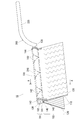
本実施の形態の清掃用具10の概要を示す斜視図が図1に示され、図1中の清掃用具10のA−A線断面における断面構造が図2に示される。図1に示すように、清掃用具10は、清掃体100及びホルダ200に大別される。
FIG. 1 shows a perspective view showing an outline of the
図1及び図2に示すように、本実施の形態の清掃体100は、いずれもシート状の繊維束110及び不織布120が、積層状に重ねられて接合線140,141,142,143,144,145にて接合されることによって形成されている。この清掃体100は、筒状部101及び刷毛部103を備える。この清掃体100が本発明における「清掃体」に相当し、筒状部101及び刷毛部103が、本発明における「筒状部」及び「刷毛部」に相当する。筒状部101は、中空筒状の収容空間102(「内部空間」ともいう)を備える構成とされる。この収容空間102が、本発明における「収容空間」に相当する。刷毛部103は、筒状部101以外の部分において刷毛状の清掃部位を形成する。これら筒状部101及び刷毛部103のいずれにおいても、内方に繊維束110が配設され、外方(表面)に不織布120が配設されるようになっている。また、本実施の形態の清掃体100では、刷毛部103の被清掃面側に繊維110束が面し、この刷毛部103のうち被清掃面と反対側の面上に筒状部101が配設される。
As shown in FIG.1 and FIG.2, as for the
なお、本実施の形態の刷毛部103は、ホルダ200が水平状に延在する状態、すなわち後述する保持部210及び把持部220が概ね水平に延在する状態において、筒状部101から垂直下向きに延在する構成とされる。ホルダ200が水平状に延在するこの状態は、作業者がホルダ200の把持部(後述する把持部220)を把持して清掃作業を行う状態と合致する。従って、この刷毛部103は、清掃作業時において下向きに延在し易く、毛足を十分に使えるため、被清掃面のごみや埃を掃き出す動作を行うのに有効である。
The
(繊維束110の構成)
繊維束110は、繊維による単一の繊維構造体や、繊維が長さ方向および/または径方向にそろった繊維構造体(撚糸、紡績糸、複数の長繊維が部分的に接続された糸材など)、ないし当該繊維構造体の集合体とされ、熱可塑性繊維を一部に含み融着(「溶着」ともいう)が可能な繊維束として構成される。この繊維束110を形成する繊維とは、糸、織物などの構成単位であり、太さに比して十分な長さを持つ、細くてたわみやすい形態のものとして規定され、典型的には長い連続状の繊維が長繊維(フィラメント)とされ、短い繊維が短繊維(ステープル)とされる。この繊維束110が、本発明における「繊維束」に相当する。この繊維束110は、典型的にはポリエチレン(PE)、ポリプロピレン(PP)、ポリエチレンテレフタレート(PET)、ナイロン、レーヨンなどを材質とし、実用上はトウを開繊することによって得られる長繊維(フィラメント)の集合体がこの繊維束110として多用される。特には、芯部分がポリプロピレン(PP)或いはポリエチレンテレフタレート(PET)であり、この芯部分の外面を覆う鞘部分がポリエチレン(PE)の複合繊維を用いて繊維束110が構成されるのが好ましい。また、繊維束110を形成する長繊維の繊度は、1〜50dtexのものが好ましく、更には2〜10dtexのものが好ましい。また、各繊維束は概ね同様の繊度の繊維から構成されてもよいし、或いは各繊維束が異なる繊度の繊維を含む構成であってもよい。なお、清掃時の掃き出し機能を向上させるためには、剛性の高い繊維、すなわち繊度が高い繊維を含む繊維束を用いるのが好ましい。
(Configuration of fiber bundle 110)
The
また、繊維束110として、フィルムをテープ状にスリットし、縦方向へ延伸させたフラットヤーンや、スプリットヤーンと称呼される熱可塑性フィルム樹脂を樹脂の配向方向と直交する方向にかきわけて、繊維状となったフィルムが網目状に接合されているものを使用してもよい。或いは、繊維束110として、エアースルー不織布などの嵩高で繊維密度の低い不織布を使用してもよい。
Further, as the
また、繊維束110を形成する繊維は、捲縮繊維を用いて構成されるのが好ましい。ここでいう捲縮繊維は、所定の巻き縮み処理が付与された繊維として構成される。このような捲縮繊維を用いると、繊維束が嵩高となり、更に捲縮部分にごみを取り込み易い構造とされる。本構造は、特にトウ繊維から形成された捲縮繊維を用いることによって実現され得る。
The fibers forming the
本実施の形態の清掃体100は、上記構成の繊維束110を備えることによって、使用時に繊維間や繊維の捲縮部分に汚れが絡まることとなり高い清掃機能を発揮する。
By providing the
(不織布120の構成)
不織布120は、機械的、化学的、熱的などの処理によって繊維を固着したり絡み合わせたりして作られるシート状の構成物であって、熱可塑性繊維を一部に含み融着(溶着)が可能な不織布とされ、複数の短冊片を有する形状の不織布として構成される。この不織布120が、本発明における「不織布」に相当する。この不織布120としては、スパンボンドやエアースルー法で形成されたものや、サーマルボンド、スパンレース、ポイントボンド、メルトブロー、ステッチボンド、ケミカルボンド、ニードルパンチなどで形成された不織布が用いられる。なお、清掃時の掃き出し機能を向上させるためには、剛性の高い不織布を用いるのが好ましい。この不織布120の短冊部分は、ジクザグ状、曲線状など種々の形状とすることができるが、清掃機能を高めるためには、短冊部分をジクザグ状として、ごみを引っ掛けて捕捉し易い形状のものを用いるのが好ましい。
また、不織布に代えて或いは加えて、ウレタン、スポンジ、職布、ネット、ワリフなどの素材を短冊状に加工したものを用いることもできる。
(Configuration of non-woven fabric 120)
The
Further, instead of or in addition to the nonwoven fabric, a material obtained by processing a material such as urethane, sponge, work cloth, net, or burif into a strip shape may be used.
本実施の形態の清掃体100は、上記構成の不織布120を備えることによって、使用時に短冊片間や短冊面に汚れが付着することとなり高い清掃機能を発揮する。また、この不織布120は、繊維束110よりも剛性が高く、これによって繊維束110同士が固まったり絡まったりするのを防止する機能を発揮する。なお、この不織布120として、捲縮繊維によって構成された不織布を用いれば、筒状部101の表面に配設された不織布120にも、清掃機能を付与することが可能となる。
By providing the
一方、ホルダ200は、上記構成の清掃体100を保持するホルダとしての機能を有し、いずれも長尺状の保持部210及び把持部220を少なくとも備える構成とされる。保持部210は、把持部220の先端に配設されるとともに、清掃体100の筒状部101に形成された収容空間102に着脱自在に収容されてこの清掃体100を保持する部位とされる。図1に示す実施の形態では、この保持部210が一本の棒状、或いは一片の板状の部位として構成される。把持部220は、保持部210の後方に連接して延在して、清掃作業時や清掃体交換作業時などにおいて、作業者が手で掴んで把持する部位とされる。本実施の形態では、これら保持部210及び把持部220の延在方向は概ね合致するように構成されている。なお、これら保持部210及び把持部220は、互いに別体として成型されたものを組み付けるように構成されてもよいし、或いは一体成型されたものとして構成されてもよい。必要に応じて清掃体100を保持部210から取り外すことによって、清掃体100の交換などが可能となる。この清掃体100は、一回使用を目安とした使い捨てタイプのものや、被清掃面から除去したごみや埃を刷毛部において保持しつつ複数回の使用を目安として交換を行う使い捨てタイプのものであってもよいし、或いは洗濯などを行ったうえで繰り返し使用することが可能なタイプのものであってもよい。
On the other hand, the
なお、本実施の形態では、収容空間102を構成する繊維束110の内面に硬化処理が施された硬化処理部104が設けられている。この硬化処理部104が、本発明における「硬化処理部」に相当する。この硬化処理部104を用いて収容空間102を構成することによって、ばらける現象が本来生じ易い繊維束110の保形性を向上させることができ、これにより保持部210を収容空間102に収容する際の収容動作の円滑化を図ることが可能となる。
In the present embodiment, a curing
また、本実施の形態では、保持部210が収容空間102に収容された使用状態で抜け難くするように、筒状部101のうち収容空間102の両端部に伸縮素材130,130が取り付けられている。各伸縮素材130は、熱可塑性繊維を少なくとも一部に含む不織布、或いは熱可塑性樹脂フィルムであって、且つ伸縮機能を有する素材からなるもの、エラストマー素材を配合した不織布、エラストマー、ウレタン、ゴムなどで形成されたものを用いて構成される。
Further, in the present embodiment, the
ここで、上記構成の清掃体100の製造方法に関し、図3及び図4を参照しながら説明する。本実施の形態の清掃体100の製造過程が図3及び図4に示される。この製造方法において、以下の第1の接合工程、硬化処理工程、折り返し工程、第2の接合工程を少なくとも順次遂行することによって、図1に示す清掃体100を製造し得る。
Here, the manufacturing method of the
(第1の接合工程)
図3に示すように、本実施の形態では、前記構成の繊維束110と、短冊片状の不織布120を積層状に重ねて互いに接合する。具体的には、これら繊維束110及び不織布120を、まず接合線140,141にて融着接合する。また、これら繊維束110及び不織布120を、接合線140と接合線141とで囲まれた不織布120上に、接合線142にてパターン状に溶着接合する。この接合線142を、接合線140と接合線141と平行状に形成された接合線とすることもできる。更に、これら繊維束110及び不織布120の両端面同士を、接合線143,144にて融着接合する。これにより、繊維束110及び不織布120からなる二層構造の繊維シートが形成される。更に、不織布120の両端部に伸縮素材130,130を接合する。
(First joining step)
As shown in FIG. 3, in the present embodiment, the
(硬化処理工程)
次に、第1の接合工程において得られた繊維シートのうち、収容空間102を構成する繊維束110の内面全体に硬化処理(熱処理)を施すことによって硬化処理部104を設ける。これにより、繊維束110及び不織布120からなる二層構造の繊維シートであって、硬化処理部104を備える繊維シートが形成される。この硬化処理に関しては、熱処理にかえて接着剤の塗布処理などを用いることもできる。また、本発明では、この硬化処理を、収容空間102の内壁面の全体または一部分において連続状或いは断続状に施すことができる。収容空間102の内壁面に部分的に硬化処理を施す際の施工箇所に関しては、筒状部101の端部、収容空間102の内壁面の上下部分、収容空間102の内壁面の或いは左右部分などを必要に応じて適宜選択することができる。
(Curing process)
Next, of the fiber sheets obtained in the first joining step, the curing
(折り返し工程)
次に、図4に示すように、硬化処理工程において得られた繊維シートを、繊維束110側が内側となるように接合線140,141にて筒状に折り返す(或いは折り曲げる)。これにより、繊維束110及び不織布120からなる二層構造の折り返し繊維シートが形成される。
(Wrapping process)
Next, as shown in FIG. 4, the fiber sheet obtained in the curing process is folded (or folded) into a cylindrical shape at the joining
(第2の接合工程)
その後、折り返し工程において得られた折り返し繊維シートの折り返し部分を接合線145にて溶着接合する。これにより、閉じた形状の収容空間102を有する中空筒状の筒状部101と、筒状部101以外の刷毛部103を備える、図1に示すような形態の清掃体100が得られることとなる。なお、上記接合線140〜145の形状に関しては、連続状の直線或いは曲線、断続状の直線或いは曲線とすることができる。
上述のように、本実施の形態の清掃体100は、繊維束110及び不織布120からなる二層構造であるため、部品点数を抑えて製造コスト低減を図るのに有効である。
(Second joining step)
Thereafter, the folded portion of the folded fiber sheet obtained in the folding step is welded and joined at the joining
As described above, since the
ホルダ200構成に関しては、図1に示すように保持部210が一本の棒状、或いは一片の板状とされた構成以外に、二本以上の保持部を有するホルダを用いることもできる。ここで、図5には、互いに平行状な二本の保持部310,310が把持部320の先端に配設された構成のホルダ300を備える清掃用具20の斜視図が示される。
Regarding the configuration of the
図5に示すようなホルダ300を用いる場合には、上記清掃体100における収容空間102が2箇所必要となる。そこで、上記第2の接合工程にて得られた清掃体100の筒状部101を用い、更にこの筒状部101の中央部分を図5中の矢印方向へと押圧していく。そして、この筒状部101の1つの筒状部分を2つの筒状部分に分割した状態で中央部分を接合する。このような方法を用いることによって、図5中の実線で示すような状態、すなわち2つの収容空間102a,102bを備える状態の筒状部101が形成された清掃体100が得られることとなる。この清掃体100の収容空間102a,102b(本発明における「収容空間」或いは「二つの収容空間」に相当する)の各々に、把持部320(本発明における「把持部」に相当する)の先端に連接する各保持部310(本発明における「保持部」に相当する)を収容することによって、図5に示す清掃用具20(本発明における「清掃用具」に相当する)が形成されることとなる。このような構成のホルダ300は、保持部の数が増えることによって使用時において保持状態の清掃体100が外れにくいという有利な効果を奏する。
When the
なお、筒状部101に2つの収容空間102a,102bを設ける方法に関しては、図5に示すように筒状部101の1つの筒状部分を2つの筒状部分に分割する方法にかえて、図6及び図7に示すような別の方法を採用することもできる。ここで、図6及び図7には、いずれも図5に示す例とは別の方法を用いて形成された清掃体100であって、筒状部101に2つの収容空間102a,102bを備える清掃体100の斜視図である。
In addition, regarding the method of providing the two
図6に示す方法では、図1に示す清掃体100を中央領域105において180度折り曲げて筒状部101をU字状とする。これによって筒状部101の両端部を収容空間102a,102bとして用いることが可能となる。また、図7に示す方法では、図1に示す清掃体100を2つ準備して、これら2つの清掃体100を並置する。これにより、一方の清掃体100の収容空間を収容空間102aとし、他方の清掃体100の収容空間を収容空間102bとすることが可能となる。図6や図7に示す方法を用いることによって、図5に示す方法を用いるのと同様に、使用時において保持状態の清掃体100が外れにくいという作用効果を奏する。また、図7に示す方法を用いる場合には、更に刷毛部103の量(ボリューム)が増えることとなり、清掃機能を高めることが可能となる。
In the method shown in FIG. 6, the
なお、上記実施の形態の清掃体100は、繊維束110及び不織布120からなる二層構造としたが、これら繊維束110及び不織布120に更なる繊維層が付加された多層構造とすることもできる。例えば、繊維束110の両面が不織布120によって挟み込まれた三層構造を採用することもできる。このような構成によれば、繊維間に空気を含み易い繊維束110を不織布120によって挟み込むことで、繊維束110内部の空気を極力追い出しながら三層の溶着を行うことができるため、溶着性能向上を図ることが可能となる。
In addition, although the
(他の実施の形態)
なお、本発明は上記の実施の形態のみに限定されるものではなく、種々の応用や変形が考えられる。例えば、上記実施の形態を応用した次の各形態を実施することもできる。
(Other embodiments)
In addition, this invention is not limited only to said embodiment, A various application and deformation | transformation can be considered. For example, each of the following embodiments to which the above embodiment is applied can be implemented.
上記実施の形態では、ホルダ200が水平状に延在する状態において、清掃体100の刷毛部103が筒状部101から垂直下向きに延在する構成について記載したが、本発明においては、この刷毛部103の延在方向は種々変更可能である。例えば、刷毛部103が筒状部101の延在方向に対し所定の角度をもって傾斜する構成や、刷毛部103が筒状部101の両側面から横向きに延在する構成などを採用することもできる。
In the above-described embodiment, the configuration in which the
10,20…清掃用具
100…清掃体
101…筒状部
102,102a,102b…収容空間
103…刷毛部
104…硬化処理部
105…中央領域
110…繊維束
120…不織布
130…伸縮素材
140,141,142,143,144,145…接合線
200,300…ホルダ
210,310…保持部
220,320…把持部
DESCRIPTION OF
Claims (8)
当該清掃体の繊維束側が内側となるように筒状に折り返されて形成された長尺状の筒状部と、
前記筒状部の内方に形成されて、清掃体保持用の保持部を着脱自在に収容する収容空間と、
前記筒状部以外において刷毛状の清掃部位を形成する刷毛部と、
前記収容空間に配設される前記繊維束にて当該繊維束の熱溶着によって硬化処理がなされた硬化処理部と、
を備え、
前記筒状部は、前記硬化処理部の前記繊維束によって前記収容空間に面する内壁面を形成する構成であることを特徴とする清掃体。 It is a cleaning body having a layer structure in which a nonwoven fabric and a fiber bundle are stacked in a laminate,
A long cylindrical portion formed by being folded into a cylindrical shape so that the fiber bundle side of the cleaning body is on the inside;
An accommodation space that is formed inward of the cylindrical portion and detachably accommodates a holding portion for holding the cleaning body; and
A brush portion that forms a brush-like cleaning site other than the tubular portion; and
A curing treatment part that has been cured by thermal welding of the fiber bundle in the fiber bundle disposed in the accommodation space;
With
The said cylindrical part is a structure which forms the inner wall face which faces the said accommodation space by the said fiber bundle of the said hardening process part, The cleaning body characterized by the above-mentioned .
前記刷毛部は、前記保持部の延在方向に沿って延在する前記長尺状の筒状部から当該筒状部の延在方向と交差する方向に延在する構成であることを特徴とする清掃体。 The cleaning body according to claim 1,
The brush portion is configured to extend from the elongated tubular portion extending along the extending direction of the holding portion in a direction intersecting the extending direction of the tubular portion. Cleaning body to do.
前記刷毛部の被清掃面側に前記繊維束が面し、この刷毛部のうち被清掃面と反対側の面上に前記筒状部が配設される構成であることを特徴とする清掃体。 The cleaning body according to claim 1 or 2,
A cleaning body characterized in that the fiber bundle faces the surface to be cleaned of the brush portion, and the cylindrical portion is disposed on the surface of the brush portion opposite to the surface to be cleaned. .
前記長尺状の筒状部は、当該筒状部を長尺方向の所定の箇所にて折り曲げて形成されたU字状とされ、当該筒状部の端部にて前記保持部を収容する二つの収容空間を備える構成であることを特徴とする清掃体。 The cleaning body according to any one of claims 1 to 3,
The long cylindrical portion is formed into a U shape formed by bending the cylindrical portion at a predetermined position in the longitudinal direction, and the holding portion is accommodated at an end of the cylindrical portion. A cleaning body comprising two housing spaces.
前記清掃体に設けられる収容空間と、
前記清掃体の収容空間に着脱自在に収容されてこの清掃体を保持する保持部と、
前記保持部に連接して配設されて作業者によって把持される把持部と、
を有する清掃用具であって、
前記清掃体は、繊維束側が内側となるように筒状に折り返されて前記収容空間を形成する長尺状の筒状部と、前記筒状部以外において刷毛状の清掃部位を形成する刷毛部と、前記収容空間に配設される前記繊維束にて当該繊維束の熱溶着によって硬化処理がなされた硬化処理部を備え、
前記筒状部は、前記硬化処理部の前記繊維束によって前記収容空間に面する内壁面を形成する構成であることを特徴とする清掃用具。 A layered cleaning body in which a nonwoven fabric and a fiber bundle are laminated, and
A storage space provided in the cleaning body;
A holding part that is detachably accommodated in an accommodation space of the cleaning body and holds the cleaning body;
A gripping part disposed in connection with the holding part and gripped by an operator;
A cleaning tool comprising:
The cleaning body is a long cylindrical portion that is folded back into a cylindrical shape so that the fiber bundle side is inside, and a brush portion that forms a brush-like cleaning site other than the cylindrical portion. And a curing treatment part that is cured by thermal welding of the fiber bundle in the fiber bundle disposed in the accommodation space ,
The said cylindrical part is a structure which forms the inner wall face which faces the said accommodation space by the said fiber bundle of the said hardening process part, The cleaning tool characterized by the above-mentioned .
前記保持部、把持部及び筒状部の延在方向が概ね合致する構成であり、
前記清掃体の前記刷毛部は、前記長尺状の筒状部から当該筒状部の延在方向と交差する方向に延在する構成であることを特徴とする清掃用具。 The cleaning tool according to claim 5,
The extending direction of the holding part, the holding part and the cylindrical part is generally matched,
The cleaning tool according to claim 1, wherein the brush portion of the cleaning body is configured to extend from the elongated cylindrical portion in a direction intersecting with an extending direction of the cylindrical portion.
前記清掃体の前記刷毛部の被清掃面側に前記繊維束が面し、この刷毛部のうち被清掃面と反対側の面上に前記筒状部が配設される構成であることを特徴とする清掃用具。 The cleaning tool according to claim 5 or 6,
The fiber bundle faces the surface to be cleaned of the brush portion of the cleaning body, and the tubular portion is arranged on the surface of the brush portion opposite to the surface to be cleaned. Cleaning tool.
前記清掃体の前記長尺状の筒状部は、当該筒状部を長尺方向の所定の箇所にて折り曲げて形成されたU字状とされ、当該筒状部の端部にて前記保持部を収容する二つの収容空間を備える構成であることを特徴とする清掃用具。 A cleaning tool according to any one of claims 5 to 7,
The long cylindrical portion of the cleaning body is formed in a U shape formed by bending the cylindrical portion at a predetermined position in the longitudinal direction, and the holding portion is held at the end of the cylindrical portion. A cleaning tool comprising two storage spaces for storing a portion.
Priority Applications (6)
| Application Number | Priority Date | Filing Date | Title |
|---|---|---|---|
| JP2006031121A JP4845525B2 (en) | 2006-02-08 | 2006-02-08 | Cleaning body and cleaning tool |
| TW096101145A TW200733927A (en) | 2006-02-08 | 2007-01-11 | Sweeper body and sweeping tool |
| PCT/JP2007/052112 WO2007091592A1 (en) | 2006-02-08 | 2007-02-07 | Cleaning body and cleaning tool |
| US12/278,303 US9089252B2 (en) | 2006-02-08 | 2007-02-07 | Cleaning element and cleaning tool |
| EP07708151.1A EP1982627B1 (en) | 2006-02-08 | 2007-02-07 | Cleaning body and cleaning tool |
| CN200780004989.1A CN101378689B (en) | 2006-02-08 | 2007-02-07 | Cleaning body and cleaning tool |
Applications Claiming Priority (1)
| Application Number | Priority Date | Filing Date | Title |
|---|---|---|---|
| JP2006031121A JP4845525B2 (en) | 2006-02-08 | 2006-02-08 | Cleaning body and cleaning tool |
Publications (2)
| Publication Number | Publication Date |
|---|---|
| JP2007209460A JP2007209460A (en) | 2007-08-23 |
| JP4845525B2 true JP4845525B2 (en) | 2011-12-28 |
Family
ID=38345188
Family Applications (1)
| Application Number | Title | Priority Date | Filing Date |
|---|---|---|---|
| JP2006031121A Expired - Fee Related JP4845525B2 (en) | 2006-02-08 | 2006-02-08 | Cleaning body and cleaning tool |
Country Status (6)
| Country | Link |
|---|---|
| US (1) | US9089252B2 (en) |
| EP (1) | EP1982627B1 (en) |
| JP (1) | JP4845525B2 (en) |
| CN (1) | CN101378689B (en) |
| TW (1) | TW200733927A (en) |
| WO (1) | WO2007091592A1 (en) |
Cited By (1)
| Publication number | Priority date | Publication date | Assignee | Title |
|---|---|---|---|---|
| KR20150114952A (en) * | 2013-02-07 | 2015-10-13 | 유니챰 가부시키가이샤 | Cleaning tool |
Families Citing this family (28)
| Publication number | Priority date | Publication date | Assignee | Title |
|---|---|---|---|---|
| US20080028560A1 (en) * | 2006-08-07 | 2008-02-07 | Nicola John Policicchio | Duster system for damp and dry dusting |
| JP5171348B2 (en) * | 2008-03-31 | 2013-03-27 | ユニ・チャーム株式会社 | Cleaning tool, cleaning body |
| JP5171347B2 (en) * | 2008-03-31 | 2013-03-27 | ユニ・チャーム株式会社 | Cleaning tool |
| KR101585636B1 (en) * | 2008-04-16 | 2016-01-14 | 가오 가부시키가이샤 | Cleaning sheet and process for producing the same |
| JP5818406B2 (en) * | 2010-02-26 | 2015-11-18 | 大王製紙株式会社 | Cleaning tool |
| US20110225756A1 (en) * | 2010-03-19 | 2011-09-22 | Quickie Manufacturing Corporation | Cleaning tool with multiple cleaning surfaces |
| US8627829B2 (en) | 2010-12-31 | 2014-01-14 | Goody Products, Inc. | Water removing hair brush |
| USD709291S1 (en) | 2011-12-30 | 2014-07-22 | Goody Products, Inc. | Hair brush |
| ITMI20121738A1 (en) * | 2012-10-16 | 2014-04-17 | Orlandi Spa | INSTRUMENT FOR CLEANING SURFACES |
| USD758740S1 (en) | 2012-12-28 | 2016-06-14 | Goody Products, Inc. | Water removing hair brush |
| JP6057707B2 (en) | 2012-12-29 | 2017-01-11 | ユニ・チャーム株式会社 | Manufacturing method of opened fiber bundle, manufacturing method of cleaning member, fiber bundle opening device, and cleaning member manufacturing system |
| JP6037828B2 (en) | 2012-12-29 | 2016-12-07 | ユニ・チャーム株式会社 | Manufacturing method of opened fiber bundle, manufacturing method of cleaning member, fiber bundle opening device, and cleaning member manufacturing system |
| US20140187406A1 (en) | 2012-12-29 | 2014-07-03 | Unicharm Corporation | Method of producing cleaning member |
| JP6080550B2 (en) | 2012-12-29 | 2017-02-15 | ユニ・チャーム株式会社 | Fusing device for sealing a belt-like sheet |
| US10098516B2 (en) | 2012-12-29 | 2018-10-16 | Unicharm Corporation | Method for producing cleaning member, and system for producing cleaning member |
| JP6073128B2 (en) | 2012-12-29 | 2017-02-01 | ユニ・チャーム株式会社 | Cutting device and method for manufacturing cleaning member using cutting device |
| JP6047400B2 (en) | 2012-12-29 | 2016-12-21 | ユニ・チャーム株式会社 | Method and apparatus for manufacturing a cleaning member |
| US20140182767A1 (en) | 2012-12-29 | 2014-07-03 | Unicharm Corporation | Method of producing cleaning member |
| JP6047401B2 (en) | 2012-12-29 | 2016-12-21 | ユニ・チャーム株式会社 | Manufacturing method of opened fiber bundle, manufacturing method of cleaning member, fiber bundle opening device, and cleaning member manufacturing system |
| JP6103945B2 (en) | 2013-01-10 | 2017-03-29 | ユニ・チャーム株式会社 | Stacking apparatus and method for manufacturing web member |
| JP6141023B2 (en) | 2013-01-10 | 2017-06-07 | ユニ・チャーム株式会社 | Manufacturing method of web member including tow |
| JP6228366B2 (en) * | 2013-02-07 | 2017-11-08 | ユニ・チャーム株式会社 | Cleaning tool |
| JP6126398B2 (en) * | 2013-02-07 | 2017-05-10 | ユニ・チャーム株式会社 | Cleaning tool |
| EP2982871A4 (en) * | 2013-04-05 | 2016-11-16 | Shikibo Ltd | Composite material lightweight coupling |
| KR102049613B1 (en) * | 2013-07-10 | 2019-11-28 | 쓰리엠 이노베이티브 프로퍼티즈 캄파니 | Toilet scrubber and toilet cleaner having the same |
| US20180042440A1 (en) * | 2015-03-12 | 2018-02-15 | Uni-Charm Corporation | Cleaning sheet and cleaning instrument |
| USD799130S1 (en) * | 2016-05-26 | 2017-10-03 | Sharkninja Operating Llc | Pad |
| CN108042065B (en) * | 2017-12-11 | 2020-11-06 | 福州永乐食品有限公司 | Multifunctional sanitary appliance |
Family Cites Families (10)
| Publication number | Priority date | Publication date | Assignee | Title |
|---|---|---|---|---|
| GB126138A (en) | 1918-05-03 | 1919-05-05 | Henry Sidebottom | Improvements in or relating to Dusters, Polishers and the like. |
| US3066344A (en) * | 1959-02-27 | 1962-12-04 | Borras Jose Garcia | Dust removers |
| JPS4838306Y1 (en) | 1968-09-21 | 1973-11-13 | ||
| JP2977477B2 (en) | 1995-12-08 | 1999-11-15 | 花王株式会社 | Cleaning tools |
| DE19835735A1 (en) | 1998-08-07 | 2000-02-17 | Lutz Bengsch | Device for cleaning in narrow vertical spaces, particularly between ribs of radiator, has holding element and soft cleaning part |
| TW200303183A (en) * | 2002-02-22 | 2003-09-01 | Yamada Chiyoe | Cleaning tool, and method for manufacturing cleaning portion constituting the cleaning tool |
| JP2005161051A (en) | 2003-12-03 | 2005-06-23 | Oimo Industrial Co Ltd | Hand mop |
| CA2555380A1 (en) * | 2004-03-08 | 2005-09-15 | Yamada, Chiyoe | Cleaning tool and method of manufacturing cleaning part thereof |
| CN2726513Y (en) * | 2004-07-16 | 2005-09-21 | 毛莹 | Cleaning brush |
| JP3107950U (en) | 2004-08-18 | 2005-04-07 | 株式会社パテントセクション | Cleaning tool |
-
2006
- 2006-02-08 JP JP2006031121A patent/JP4845525B2/en not_active Expired - Fee Related
-
2007
- 2007-01-11 TW TW096101145A patent/TW200733927A/en not_active IP Right Cessation
- 2007-02-07 WO PCT/JP2007/052112 patent/WO2007091592A1/en active Application Filing
- 2007-02-07 US US12/278,303 patent/US9089252B2/en not_active Expired - Fee Related
- 2007-02-07 CN CN200780004989.1A patent/CN101378689B/en not_active Expired - Fee Related
- 2007-02-07 EP EP07708151.1A patent/EP1982627B1/en not_active Not-in-force
Cited By (2)
| Publication number | Priority date | Publication date | Assignee | Title |
|---|---|---|---|---|
| KR20150114952A (en) * | 2013-02-07 | 2015-10-13 | 유니챰 가부시키가이샤 | Cleaning tool |
| KR102175025B1 (en) * | 2013-02-07 | 2020-11-05 | 유니챰 가부시키가이샤 | Cleaning tool |
Also Published As
| Publication number | Publication date |
|---|---|
| CN101378689A (en) | 2009-03-04 |
| EP1982627B1 (en) | 2013-08-07 |
| JP2007209460A (en) | 2007-08-23 |
| TW200733927A (en) | 2007-09-16 |
| US20090165230A1 (en) | 2009-07-02 |
| CN101378689B (en) | 2011-11-30 |
| TWI305719B (en) | 2009-02-01 |
| WO2007091592A1 (en) | 2007-08-16 |
| US9089252B2 (en) | 2015-07-28 |
| EP1982627A1 (en) | 2008-10-22 |
| EP1982627A4 (en) | 2010-04-07 |
Similar Documents
| Publication | Publication Date | Title |
|---|---|---|
| JP4845525B2 (en) | Cleaning body and cleaning tool | |
| JP4597880B2 (en) | Cleaning body and cleaning tool | |
| JP4869984B2 (en) | Cleaning tool | |
| JP4731433B2 (en) | Cleaning body and cleaning tool | |
| JP5171348B2 (en) | Cleaning tool, cleaning body | |
| JP5171347B2 (en) | Cleaning tool | |
| JP4823105B2 (en) | Cleaning tool and cleaning body | |
| JP5685093B2 (en) | Cleaning tool, cleaning article | |
| JP4934463B2 (en) | Cleaning tool and cleaning body | |
| JP5221624B2 (en) | Cleaning body and cleaning tool | |
| JP5657525B2 (en) | Cleaning tool, cleaning body | |
| JP5588431B2 (en) | Cleaning tool, cleaning body | |
| JP5503640B2 (en) | Cleaning tool, cleaning body | |
| JP5637875B2 (en) | Cleaning tool, cleaning article | |
| JP5147909B2 (en) | Cleaning body and cleaning tool |
Legal Events
| Date | Code | Title | Description |
|---|---|---|---|
| A621 | Written request for application examination |
Free format text: JAPANESE INTERMEDIATE CODE: A621 Effective date: 20090114 |
|
| A131 | Notification of reasons for refusal |
Free format text: JAPANESE INTERMEDIATE CODE: A131 Effective date: 20100827 |
|
| A02 | Decision of refusal |
Free format text: JAPANESE INTERMEDIATE CODE: A02 Effective date: 20110310 |
|
| A521 | Request for written amendment filed |
Free format text: JAPANESE INTERMEDIATE CODE: A523 Effective date: 20110607 |
|
| A911 | Transfer to examiner for re-examination before appeal (zenchi) |
Free format text: JAPANESE INTERMEDIATE CODE: A911 Effective date: 20110614 |
|
| TRDD | Decision of grant or rejection written | ||
| A01 | Written decision to grant a patent or to grant a registration (utility model) |
Free format text: JAPANESE INTERMEDIATE CODE: A01 Effective date: 20110914 |
|
| A01 | Written decision to grant a patent or to grant a registration (utility model) |
Free format text: JAPANESE INTERMEDIATE CODE: A01 |
|
| A61 | First payment of annual fees (during grant procedure) |
Free format text: JAPANESE INTERMEDIATE CODE: A61 Effective date: 20111011 |
|
| FPAY | Renewal fee payment (event date is renewal date of database) |
Free format text: PAYMENT UNTIL: 20141021 Year of fee payment: 3 |
|
| R150 | Certificate of patent or registration of utility model |
Ref document number: 4845525 Country of ref document: JP Free format text: JAPANESE INTERMEDIATE CODE: R150 Free format text: JAPANESE INTERMEDIATE CODE: R150 |
|
| R250 | Receipt of annual fees |
Free format text: JAPANESE INTERMEDIATE CODE: R250 |
|
| R250 | Receipt of annual fees |
Free format text: JAPANESE INTERMEDIATE CODE: R250 |
|
| R250 | Receipt of annual fees |
Free format text: JAPANESE INTERMEDIATE CODE: R250 |
|
| R250 | Receipt of annual fees |
Free format text: JAPANESE INTERMEDIATE CODE: R250 |
|
| R250 | Receipt of annual fees |
Free format text: JAPANESE INTERMEDIATE CODE: R250 |
|
| R250 | Receipt of annual fees |
Free format text: JAPANESE INTERMEDIATE CODE: R250 |
|
| R250 | Receipt of annual fees |
Free format text: JAPANESE INTERMEDIATE CODE: R250 |
|
| R250 | Receipt of annual fees |
Free format text: JAPANESE INTERMEDIATE CODE: R250 |
|
| R250 | Receipt of annual fees |
Free format text: JAPANESE INTERMEDIATE CODE: R250 |
|
| LAPS | Cancellation because of no payment of annual fees |