JP4842007B2 - Waste heat recovery boiler - Google Patents
Waste heat recovery boiler Download PDFInfo
- Publication number
- JP4842007B2 JP4842007B2 JP2006128346A JP2006128346A JP4842007B2 JP 4842007 B2 JP4842007 B2 JP 4842007B2 JP 2006128346 A JP2006128346 A JP 2006128346A JP 2006128346 A JP2006128346 A JP 2006128346A JP 4842007 B2 JP4842007 B2 JP 4842007B2
- Authority
- JP
- Japan
- Prior art keywords
- evaporator
- bypass
- pressure
- exhaust gas
- recovery boiler
- Prior art date
- Legal status (The legal status is an assumption and is not a legal conclusion. Google has not performed a legal analysis and makes no representation as to the accuracy of the status listed.)
- Expired - Fee Related
Links
- 238000011084 recovery Methods 0.000 title claims description 50
- 239000002918 waste heat Substances 0.000 title description 7
- XLYOFNOQVPJJNP-UHFFFAOYSA-N water Substances O XLYOFNOQVPJJNP-UHFFFAOYSA-N 0.000 claims description 30
- 238000010521 absorption reaction Methods 0.000 claims description 10
- 238000011144 upstream manufacturing Methods 0.000 claims description 9
- 238000010438 heat treatment Methods 0.000 claims description 3
- 239000013589 supplement Substances 0.000 claims description 2
- 239000007789 gas Substances 0.000 description 74
- 238000002485 combustion reaction Methods 0.000 description 8
- 238000010248 power generation Methods 0.000 description 7
- 238000010586 diagram Methods 0.000 description 5
- UGFAIRIUMAVXCW-UHFFFAOYSA-N Carbon monoxide Chemical compound [O+]#[C-] UGFAIRIUMAVXCW-UHFFFAOYSA-N 0.000 description 2
- 239000003054 catalyst Substances 0.000 description 2
- 238000013461 design Methods 0.000 description 2
- 239000003546 flue gas Substances 0.000 description 2
- VNWKTOKETHGBQD-UHFFFAOYSA-N methane Chemical compound C VNWKTOKETHGBQD-UHFFFAOYSA-N 0.000 description 2
- 230000002411 adverse Effects 0.000 description 1
- 238000007796 conventional method Methods 0.000 description 1
- 238000000034 method Methods 0.000 description 1
- 239000000203 mixture Substances 0.000 description 1
- 239000003345 natural gas Substances 0.000 description 1
- 238000013021 overheating Methods 0.000 description 1
- 238000000926 separation method Methods 0.000 description 1
- 238000012546 transfer Methods 0.000 description 1
- 230000005514 two-phase flow Effects 0.000 description 1
Images


Landscapes
- Control Of Steam Boilers And Waste-Gas Boilers (AREA)
Description
本発明は、排熱回収ボイラに係り、特に大容量高効率化に好適な排熱回収ボイラに関する。 The present invention relates to an exhaust heat recovery boiler, and more particularly to an exhaust heat recovery boiler suitable for increasing the capacity and efficiency.
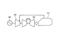
一般的なコンバインドサイクル発電設備のプラント構成について図7,図8を参照して説明する。
ガスタービン36では天然ガス等の燃焼により発電を行い、高温のガスタービン排ガスは排熱回収ボイラ37に送られる。排熱回収ボイラ37では排ガスからの熱回収により給水が蒸気になり、発生した蒸気は蒸気タービン39に送られて発電を行う。
A plant configuration of a general combined cycle power generation facility will be described with reference to FIGS.
The
この際、図7に示すようにガスタービン36,蒸気タービン39,発電機40のそれぞれ1台が同軸で接続されて、排熱回収ボイラ37が1台設置された一軸システムと、図8に示すように2台以上のガスタービン36及び排熱回収ボイラ37に1台の蒸気タービン39が組み合わされ、それぞれに発電機40,41が設置された多軸システムがある。多軸システムは、排熱回収ボイラ37から蒸気タービン39に送られる蒸気量がガスタービン負荷だけでなく運転台数によっても変化することから、一軸システムに比べて蒸気システムでの運用範囲が広くなる。
At this time, as shown in FIG. 7, each of the
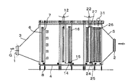
従来の貫流式排熱回収ボイラの断面図を図9,図10に示す。図9は貫流式排熱回収ボイラの側面断面図、図10はその貫流式排熱回収ボイラの平面断面図である。 9 and 10 are sectional views of a conventional once-through exhaust heat recovery boiler. FIG. 9 is a side sectional view of the once-through exhaust heat recovery boiler, and FIG. 10 is a plan sectional view of the once-through exhaust heat recovery boiler.
これらの図において、1はガス入口、2はガス出口、3は入口ダクト、4は本体ケーシング、5は出口ダクト、6は高圧三次過熱器、7は二次再熱器、8は助燃バーナ、9は高圧二次過熱器、10は再熱器、11は高圧一次過熱器、12は高圧汽水分離器、13は高圧二次蒸発器、14は高圧分配管、15は高圧分配管、16は高圧一次蒸発器出口管、17は高圧一次蒸発器、18は排煙脱硝触媒、19は中圧過熱器、20は高圧三次節炭器、21は低圧過熱器、22は中圧汽水分離器、23は中圧二次蒸発器、24は中圧分配管、25は中圧分配管、26は中圧一次蒸発器出口管、27は中圧一次蒸発器、28は高圧二次節炭器、29は中圧節炭器、30は高圧一次節炭器、31は低圧蒸気ドラム、32は低圧蒸発器、33は低圧節炭器である。 In these drawings, 1 is a gas inlet, 2 is a gas outlet, 3 is an inlet duct, 4 is a main body casing, 5 is an outlet duct, 6 is a high-pressure tertiary superheater, 7 is a secondary reheater, 8 is an auxiliary burner, 9 is a high-pressure secondary superheater, 10 is a reheater, 11 is a high-pressure primary superheater, 12 is a high-pressure steam separator, 13 is a high-pressure secondary evaporator, 14 is a high-pressure distribution pipe, 15 is a high-pressure distribution pipe, and 16 is High pressure primary evaporator outlet pipe, 17 is a high pressure primary evaporator, 18 is a flue gas denitration catalyst, 19 is a medium pressure superheater, 20 is a high pressure tertiary economizer, 21 is a low pressure superheater, 22 is a medium pressure brackish water separator, 23 is a medium pressure secondary evaporator, 24 is a medium pressure distribution pipe, 25 is a medium pressure distribution pipe, 26 is a medium pressure primary evaporator outlet pipe, 27 is a medium pressure primary evaporator, 28 is a high pressure secondary economizer, 29 Is a medium pressure economizer, 30 is a high pressure primary economizer, 31 is a low pressure steam drum, 32 is a low pressure evaporator, and 33 is a low pressure economizer. That.
図10に示されているように、排ガスGの流れ方向前流側に高圧二次蒸発器13,後流側に高圧一次蒸発器17が設置され、高圧一次蒸発器17の出口の汽水混合流は高圧二次蒸発器13に導入され、高圧二次蒸発器13の出口に高圧汽水分離器12が接続されている。
As shown in FIG. 10, a high-pressure
排熱回収ボイラには助燃バーナ8が設置されており、発生蒸気量を増やし、蒸気タービンの出力を増加させることができる。助燃バーナ8は通常、高圧蒸発器より排ガス前流側の高圧過熱器と再熱器の中間あるいは排熱回収ボイラの入口側に設置されて、排ガス温度のみを上昇させる。
An
そのため蒸気量増加に伴い、蒸気タービンの運用範囲が広がるだけでなく、排熱回収ボイラ内での排ガス特性が変化することから、一次蒸発器出口での汽水混合割合や二次蒸発器出口の過熱度の変化幅が大きく広がる。 Therefore, not only the operating range of the steam turbine is expanded with the increase in steam volume, but also the exhaust gas characteristics in the exhaust heat recovery boiler change, so the brackish water mixing ratio at the outlet of the primary evaporator and the overheating of the outlet of the secondary evaporator The degree of change is greatly expanded.
ここで高圧一次蒸発器及び高圧二次蒸発器の分割に当たっては、高圧一次蒸発器出口における汽水混合割合を通常50%から70%程度になるように設定し、高圧ニ次蒸発器出口の過熱度は通常20℃から50℃程度になるように設計する。 Here, when dividing the high-pressure primary evaporator and the high-pressure secondary evaporator, the mixing ratio of the brackish water at the outlet of the high-pressure primary evaporator is usually set to about 50% to 70%, and the degree of superheat at the outlet of the high-pressure secondary evaporator Is normally designed to be about 20 ° C to 50 ° C.
運転時には高圧二次蒸発器出口の過熱度を監視し、設定温度になるよう給水流量を制御する。その際、高圧一次蒸発器出口における汽水混合割合は設計の範囲内で運用されることとなる。しかし、ガスタービンの負荷の高低に伴うガスタービンからの排ガスの流量と温度の傾向によっては、高圧一次蒸発器出口における汽水混合割合及び高圧二次蒸発器出口の過熱度は前記適正値を外れる傾向となり、多軸システム及び助燃付の貫流式排熱回収ボイラでは特に顕著になる。 During operation, the superheat degree at the outlet of the high-pressure secondary evaporator is monitored, and the feed water flow rate is controlled so as to reach the set temperature. At that time, the brackish water mixing ratio at the outlet of the high-pressure primary evaporator is operated within the design range. However, depending on the trends in the flow rate and temperature of the exhaust gas from the gas turbine due to the gas turbine load, the mixing ratio of the brackish water at the outlet of the high-pressure primary evaporator and the superheat degree at the outlet of the high-pressure secondary evaporator tend to deviate from the appropriate values. This is particularly noticeable in multi-axis systems and once-through exhaust heat recovery boilers with auxiliary combustion.
この種のボイラに関しては、例えば下記の特許文献1を挙げることができる。
ところで前述した従来の排熱回収ボイラでは、一次蒸発器、特に高圧一次蒸発器の出口における汽水混合割合及び二次蒸発器、特に高圧二次蒸発器の出口の過熱度を広運用域で適正に維持することが難しい。 By the way, in the conventional exhaust heat recovery boiler described above, the mixing ratio of the brackish water at the outlet of the primary evaporator, particularly the high-pressure primary evaporator, and the superheat degree at the outlet of the secondary evaporator, particularly the high-pressure secondary evaporator, are appropriately adjusted in a wide operation area. Difficult to maintain.
本発明の目的は、このような従来技術の欠点を解消し、一次蒸発器出口における汽水混合割合及び二次蒸発器出口の過熱度を広運用域で適正に維持できる排熱回収ボイラを提供することにある。 The object of the present invention is to provide a waste heat recovery boiler that can eliminate such drawbacks of the prior art and can appropriately maintain the mixing ratio of the brackish water at the outlet of the primary evaporator and the degree of superheat at the outlet of the secondary evaporator in a wide operation area. There is.
前記目的を達成するため本発明の第1の手段は、
ガスタービンからの排ガス流れ方向前流側に二次蒸発器を設置し、その二次蒸発器の排ガス流れ方向後流側に一次蒸発器を設置して、その一次蒸発器出口の汽水混合流を前記二次蒸発器に導入し、その二次蒸発器の出口に汽水分離器を接続した排熱回収ボイラにおいて、
前記二次蒸発器の管群内に、前記排ガスの一部を直接前記一次蒸発器に導入するバイパス通路を排ガスの流れ方向と交叉する方向に複数箇所形成するとともに、各バイパス通路のガスバイパス量を調節するためのバイパスダンパーを設け、
前記ガスタービンの負荷に基づいて前記バイパスダンパーの開度を調整することにより、前記一次蒸発器と二次蒸発器の吸熱割合を調節する構成になっていることを特徴とするものである。
In order to achieve the above object, the first means of the present invention is as follows:
A secondary evaporator is installed on the upstream side in the exhaust gas flow direction from the gas turbine, a primary evaporator is installed on the downstream side in the exhaust gas flow direction of the secondary evaporator, and the brackish water mixed flow at the outlet of the primary evaporator is In the exhaust heat recovery boiler that is introduced into the secondary evaporator and connected with a brackish water separator at the outlet of the secondary evaporator,
In the tube group of the secondary evaporator, a plurality of bypass passages for introducing a part of the exhaust gas directly into the primary evaporator are formed in a direction crossing the flow direction of the exhaust gas, and the amount of gas bypass in each bypass passage Provide a bypass damper to adjust the
The heat absorption ratio of the primary evaporator and the secondary evaporator is adjusted by adjusting the opening degree of the bypass damper based on the load of the gas turbine .
本発明の第2の手段は、
ガスタービンからの排ガス流れ方向前流側に二次蒸発器を設置し、その二次蒸発器の排ガス流れ方向後流側に一次蒸発器を設置して、その一次蒸発器出口の汽水混合流を前記二次蒸発器に導入し、その二次蒸発器の出口に汽水分離器を接続し、前記一次蒸発器の排ガス流れ方向後流側に他の熱交換器を設置した排熱回収ボイラにおいて、
前記二次蒸発器の管群内に、前記排ガスの一部を直接前記一次蒸発器に導入する第1のバイパス通路を排ガスの流れ方向と交叉する方向に複数箇所形成するとともに、各第1のバイパス通路のガスバイパス量を調節するための第1のバイパスダンパーを設け、
前記一次蒸発器の管群内に、前記排ガスの一部を直接前記他の熱交換器に導入する第2のバイパス通路を排ガスの流れ方向と交叉する方向に複数箇所形成するとともに、各第2のバイパス通路のガスバイパス量を調節するための第2のバイパスダンパーを設けて、
前記ガスタービンの負荷に基づいて前記第1のバイパスダンパーの開度を調整することにより、前記一次蒸発器と二次蒸発器の吸熱割合を調節する構成になっていることを特徴とするものである。
The second means of the present invention is:
A secondary evaporator is installed on the upstream side in the exhaust gas flow direction from the gas turbine, a primary evaporator is installed on the downstream side in the exhaust gas flow direction of the secondary evaporator, and the brackish water mixed flow at the outlet of the primary evaporator is In the exhaust heat recovery boiler that is introduced into the secondary evaporator, a brackish water separator is connected to the outlet of the secondary evaporator, and another heat exchanger is installed on the downstream side in the exhaust gas flow direction of the primary evaporator,
In the tube group of the secondary evaporator, a plurality of first bypass passages for introducing a part of the exhaust gas directly into the primary evaporator are formed in a direction crossing the flow direction of the exhaust gas, and each first Providing a first bypass damper for adjusting the gas bypass amount of the bypass passage;
In the tube group of the primary evaporator, a plurality of second bypass passages for introducing a part of the exhaust gas directly into the other heat exchanger are formed in a direction crossing the flow direction of the exhaust gas, and each second A second bypass damper for adjusting the gas bypass amount of the bypass passage of
The heat absorption ratio of the primary evaporator and the secondary evaporator is adjusted by adjusting the opening degree of the first bypass damper based on the load of the gas turbine. is there.
本発明の第3の手段は前記第1または第2の手段において、
前記二次蒸発器ならびに一次蒸発器が高圧二次蒸発器ならびに高圧一次蒸発器であって、前記二次蒸発器内のバイパスダンパーの開度調整により、前記高圧二次蒸発器出口における過熱度が20℃から50℃の範囲に、前記高圧一次蒸発器出口における汽水混合流中の蒸気の割合が50%から70%の範囲になるように調節されることを特徴とするものである。
A third means of the present invention is the first or second means ,
The secondary evaporator and the primary evaporator are a high-pressure secondary evaporator and a high-pressure primary evaporator, and the degree of superheat at the outlet of the high-pressure secondary evaporator is adjusted by adjusting the opening of a bypass damper in the secondary evaporator. In the range of 20 ° C. to 50 ° C., the ratio of steam in the brackish water mixed flow at the outlet of the high pressure primary evaporator is adjusted to be in the range of 50% to 70% .
本発明の第4の手段は前記第1ないし第3の手段のいずれかにおいて、
前記二次蒸発器の排ガス流れ方向前流側に前記ガスタービンの排ガス熱量を補う助熱装置が設けられ、
前記ガスタービンの負荷ならびに前記助熱装置の助熱量に基づいて、前記二次蒸発器内に設けられているバイパスダンパーの開度を調整する構成になっていることを特徴とするものである。
According to a fourth means of the present invention, in any one of the first to third means,
An auxiliary heating device is provided on the upstream side in the exhaust gas flow direction of the secondary evaporator to supplement the heat amount of the exhaust gas of the gas turbine.
The opening degree of the bypass damper provided in the secondary evaporator is adjusted based on the load of the gas turbine and the amount of auxiliary heat of the auxiliary heating device .
本発明は前述のような構成になっており、二次蒸発器と一次蒸発器の吸収熱量の割合を調節することができ、一次蒸発器出口における汽水混合割合及び二次蒸発器出口の過熱度を広運用域で適正に維持できる排熱回収ボイラを提供することができる。 The present invention is configured as described above, the ratio of the amount of heat absorbed by the secondary evaporator and the primary evaporator can be adjusted, the mixing ratio of brackish water at the outlet of the primary evaporator and the degree of superheat at the outlet of the secondary evaporator It is possible to provide an exhaust heat recovery boiler that can properly maintain a wide operating area.
ガスタービンの排ガスから熱を回収し蒸気を発生して、その蒸気により蒸気タービンを駆動して発電する、所謂、コンバインドサイクル発電設備において、ガスタービンの排ガスから熱を回収する設備として排熱回収ボイラが設置される。このコンバインド発電設備の特長を生かし、急速起動・停止運用による起動損失の低減,蒸気条件の高級化のよる発電効率向上策として貫流式の排熱回収ボイラが採用される。また大型のコンバインドサイクル発電設備では、この排熱回収ボイラの蒸気系統を高圧系,中圧再熱系,低圧系の3系統で構成して、排熱回収の効率向上を図っている。 In a so-called combined cycle power generation facility that recovers heat from the exhaust gas of the gas turbine to generate steam and drives the steam turbine to generate electric power, the exhaust heat recovery boiler is used as a facility for recovering heat from the exhaust gas of the gas turbine. Is installed. Taking advantage of this combined power generation facility, a once-through exhaust heat recovery boiler is adopted as a measure to improve power generation efficiency by reducing start-up loss by rapid start / stop operation and upgrading steam conditions. In a large combined cycle power generation facility, the steam system of this exhaust heat recovery boiler is composed of three systems: a high pressure system, an intermediate pressure reheat system, and a low pressure system, to improve the efficiency of exhaust heat recovery.
このような再熱三重圧方式で貫流式を構成した場合、蒸発器の構成は貫流式の設計上、一次蒸発器と二次蒸発器の組み合わせとなる。排ガス流れ方向前流側に二次蒸発器、後流側に一次蒸発器を配置し、一次蒸発器出口の汽水混合流を二次蒸発器に導入して、二次蒸発器の出口に汽水分離器を設備する。 When the once-through type is constituted by such a reheat triple pressure method, the structure of the evaporator is a combination of the primary evaporator and the secondary evaporator in terms of the once-through type design. A secondary evaporator is arranged on the upstream side in the exhaust gas flow direction, a primary evaporator is arranged on the downstream side, and the brackish water mixture at the outlet of the primary evaporator is introduced into the secondary evaporator, and brackish water is separated at the outlet of the secondary evaporator. Install equipment.
その際、二次蒸発器の出口温度については、過熱度を一定の温度内で維持し続けることが求められる。また一次蒸発器出口での蒸気含有率についても、安定した管内流動を維持するため一定の範囲内で運用する必要がある。 At that time, regarding the outlet temperature of the secondary evaporator, it is required to keep the superheat degree within a certain temperature. Also, the steam content at the outlet of the primary evaporator must be operated within a certain range in order to maintain a stable flow in the pipe.
ここで二次蒸発器の管群の間に排ガスをバイパスして直接一次蒸発器に導入できる通路を設け、且つその通路のガスバイパス量を調節するためのダンパーを設けることにより、一次蒸発器と二次蒸発器の吸収熱量を調節している。一次蒸発器と二次蒸発器の吸収熱量を調節は、一次蒸発器バイパスまたは一次蒸発器およびニ次蒸発器の両方のバイパスによっても可能である。 Here, a passage through which exhaust gas can be bypassed and introduced directly into the primary evaporator is provided between the tube groups of the secondary evaporator, and a damper for adjusting the gas bypass amount of the passage is provided, so that the primary evaporator and the The amount of heat absorbed by the secondary evaporator is adjusted. The amount of heat absorbed by the primary and secondary evaporators can also be adjusted by primary evaporator bypass or by bypass of both primary and secondary evaporators.
このように各蒸発器での吸収熱量を調節可能とすることにより、二次蒸発器出口の過熱度及び一次蒸発器出口の蒸気含有率を最適な値とすることができる。貫流式の採用は、前記貫流式の利点から高圧系のみ或いは高圧系と中圧系の2系統の場合が多い。 Thus, by making it possible to adjust the amount of heat absorbed by each evaporator, the superheat degree at the outlet of the secondary evaporator and the vapor content at the outlet of the primary evaporator can be set to optimum values. The adoption of the once-through type is often the case of only the high-pressure system or two systems of the high-pressure system and the intermediate-pressure system because of the advantage of the once-through type.
本発明はプラント出力の運用範囲が比較的広い,助燃付排熱回収ボイラ及び多軸方式のコンバインドサイクルプラントに対し特に有効である。 The present invention is particularly effective for a waste heat recovery boiler with auxiliary combustion and a multi-shaft combined cycle plant having a relatively wide operating range of plant output.
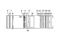
次に本発明の実施形態を図とともに説明する。図1ないし図3は第1実施形態を説明するための図であり、図1は排熱回収ボイラの側面断面図、図2はその排熱回収ボイラの平面断面図、図3(a),(b)は排ガスバイパスダンパー部の動作を説明するための図である。 Next, embodiments of the present invention will be described with reference to the drawings. 1 to 3 are views for explaining the first embodiment, FIG. 1 is a side sectional view of the exhaust heat recovery boiler, FIG. 2 is a plan sectional view of the exhaust heat recovery boiler, FIG. (B) is a figure for demonstrating operation | movement of an exhaust gas bypass damper part.
図1ならびに図2に示すように、ガスタービンからの排ガスGは排熱回収ボイラ入口1から導入され、入口ダクト3で流路を拡大された後、本体ケーシング4内に設置された最初の熱交換部である高圧三次過熱器6,二次再熱器7で熱交換される。その後、助燃バーナ8で再度温度が上昇され、高圧二次過熱器9,一次再熱器10,高圧一次過熱器11で順次熱交換される。
As shown in FIG. 1 and FIG. 2, the exhaust gas G from the gas turbine is introduced from the exhaust heat recovery boiler inlet 1, expanded in the flow path by the inlet duct 3, and then the initial heat installed in the
一方、高圧給水は高圧一次節炭器30,高圧二次節炭器28,高圧三次節炭器20を通過することにより予熱され、高圧一次蒸発器17で50%〜70%程度蒸発され、出口連絡管で分配器15に供給されて、汽水二相流をこの分配器15で均等に分配させ、さらに分配管14で高圧二次蒸発器13に導入し、個々で過熱度20℃から50℃過熱されて、汽水分配器12で汽水分離の後,高圧一次過熱器11に供給される。
On the other hand, the high-pressure feed water is preheated by passing through the high-pressure primary economizer 30, the high-pressure
ここで高圧一次蒸発器17と高圧二次蒸発器13の出口における蒸気の状態は、前記汽水混合比および過熱度の状態にあるのが好ましいが、ガスタービンの負荷あるいは助燃の量によっては運用全域において適切な状態にすることが困難になる。
Here, the state of steam at the outlets of the high-pressure
そこで図2に示すように、高圧二次蒸発器13の管群の一部にガスバイパス路34をガスの流れ方向と交叉する方向に数箇所設け、各ガスバイパス路34にガスのバイパス量を調節するためのバイパスダンパー35を設ける。そしてガスタービンの負荷,助燃量に基いて、前記バイパスダンパー35の開度を調整することにより、高圧一次蒸発器17と高圧二次蒸発器13の吸熱割合を調節する。
Therefore, as shown in FIG. 2, several
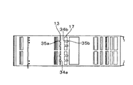
排熱回収ボイラの伝熱管群はガス流路断面に対しガス流れ方向の幅が非常に短いことから従来型ボイラにおける節炭器バイパスのような外部への排ガスのバイパス流路の採用は構造的に困難であり,バイパス後の排ガス混合が適切に行われず性能に悪影響を与える可能性が高い。そのため図3に示す排ガスバイパスが最適であり、図3に示すバイパスダンパーはルーバータイプで流路幅方向に数箇所設置される。 The heat transfer tube group of the exhaust heat recovery boiler has a very short width in the gas flow direction relative to the cross section of the gas flow path, so the adoption of an external exhaust gas bypass path such as a economizer bypass in a conventional boiler is structural. It is difficult to mix the exhaust gas after bypassing, and there is a high possibility that the performance will be adversely affected. Therefore, the exhaust gas bypass shown in FIG. 3 is optimal, and the bypass damper shown in FIG. 3 is a louver type and is installed at several places in the flow path width direction.
図3はこのバイパス部の詳細を示す図で、高圧二次蒸発器13の管群の一部にガスバイパス路34が設けられ、そのガスバイパス路34のガス入口側にバイパスダンパー35が設けられている。同図(a)はバイパスダンパー35が開いた状態、同図(b)はバイパスダンパー35が閉じた状態を、それぞれ示している。
FIG. 3 is a diagram showing details of the bypass section. A
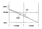
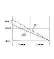
図4は、ガスタービン100%負荷とさらに助燃をした場合の高圧一次蒸発器17と高圧二次蒸発器13の吸収熱量特性を示す図である。本実施形態では、高圧二次蒸発器13の管群内に設置されているバイパスダンパー35を開いて、高圧二次蒸発器13での吸熱量を減少して、その分後流側に設置されている高圧一次蒸発器17での吸熱量を増加することができる。助燃時にも非助燃時の状態近くに高圧一次蒸発器17および高圧二次蒸発器13の状態を維持することができる。
FIG. 4 is a diagram showing the absorption heat quantity characteristics of the high-pressure
図11はガスバイパス調節が行なわれていない従来技術の同様の吸収熱量特性を示す図で、図4に示す吸収熱量特性と大きく異なり、従来技術においては前述のような技術的課題を有している。 FIG. 11 is a diagram showing a similar absorption heat quantity characteristic of the prior art in which gas bypass adjustment is not performed. Unlike the absorption heat quantity characteristic shown in FIG. 4, the conventional technique has the above-described technical problems. Yes.
図5は、本発明の第2実施形態に係る排熱回収ボイラの平面断面図である。この実施形態の場合、高圧一次蒸発器17側にガスバイパス路34とそれを開閉するバイパスダンパー35が設けられている。
FIG. 5 is a plan sectional view of an exhaust heat recovery boiler according to the second embodiment of the present invention. In the case of this embodiment, a
図6は、本発明の第3実施形態に係る排熱回収ボイラの平面断面図である。この実施形態の場合、二次蒸発器13に第1のバイパス通路34aと、第1のダンパー35aとを設け、一次蒸発器17に第2のバイパス通路34bと第2のダンパー35bとを設けている。
FIG. 6 is a plan sectional view of an exhaust heat recovery boiler according to the third embodiment of the present invention. In the case of this embodiment, the
この第2,3実施形態においても高圧一次蒸発器17と高圧二次蒸発器13の吸収熱量の割合を適宜調整することができる。
Also in the second and third embodiments, the ratio of the amount of heat absorbed by the high-pressure
本実施形態は高圧系の場合について説明したが、中圧系も同様である。なお、低圧系は貫流式の利点がないので自然循環式を採用するのが通常である。 Although the present embodiment has been described for the case of the high pressure system, the same applies to the intermediate pressure system. Since the low pressure system does not have the advantage of the once-through type, the natural circulation type is usually adopted.
1:ガス入口、2:ガス出口、3:入口ダクト、4:本体ケーシング、5:出口ダクト、6:高圧三次過熱器、7:二次再熱器、8:助燃バーナ、9:高圧二次過熱器、10:一次再熱器、11:高圧一次過熱器、12:高圧汽水分離器、13:高圧二次蒸発器、14:高圧分配管、15:高圧分配器、16:高圧一次蒸発器出口管、17:高圧一次蒸発器、18:排煙脱硝触媒、19:中圧過熱器、20:高圧三次節炭器、21:低圧過熱器、22:中圧汽水分離器、23:中圧二次蒸発器、24:中圧分配管、25:中圧分配器、26:中圧一次蒸発器出口管、27:中圧一次蒸発器、28:高圧二次節炭器、29:中圧節炭器、30:高圧一次節炭器、31:低圧蒸気ドラム、32:低圧蒸発器、33:低圧節炭器、34:排ガスバイパス、35:排ガスバイパスダンパー、36:ガスタービン、37:排熱回収ボイラ、39:蒸気タービン、40:蒸気タービン発電機、41:ガスタービン発電機、42:高圧主蒸気管、43:高温再熱蒸気管、44:低温再熱蒸気管、45:低圧主蒸気、G:排ガス。 1: Gas inlet, 2: Gas outlet, 3: Inlet duct, 4: Main body casing, 5: Outlet duct, 6: High pressure tertiary superheater, 7: Secondary reheater, 8: Auxiliary burner, 9: High pressure secondary Superheater, 10: Primary reheater, 11: High pressure primary superheater, 12: High pressure steam separator, 13: High pressure secondary evaporator, 14: High pressure distribution pipe, 15: High pressure distributor, 16: High pressure primary evaporator Outlet pipe, 17: High pressure primary evaporator, 18: Flue gas denitration catalyst, 19: Medium pressure superheater, 20: High pressure tertiary economizer, 21: Low pressure superheater, 22: Medium pressure brackish water separator, 23: Medium pressure Secondary evaporator, 24: Medium pressure distribution pipe, 25: Medium pressure distributor, 26: Medium pressure primary evaporator outlet pipe, 27: Medium pressure primary evaporator, 28: High pressure secondary economizer, 29: Medium pressure node Carbonizer, 30: High pressure primary economizer, 31: Low pressure steam drum, 32: Low pressure evaporator, 33: Low pressure economizer, 34: Exhaust gas 35: exhaust gas bypass damper, 36: gas turbine, 37: exhaust heat recovery boiler, 39: steam turbine, 40: steam turbine generator, 41: gas turbine generator, 42: high-pressure main steam pipe, 43: high temperature Thermal steam pipe, 44: low-temperature reheat steam pipe, 45: low-pressure main steam, G: exhaust gas.
Claims (4)
前記二次蒸発器の管群内に、前記排ガスの一部を直接前記一次蒸発器に導入するバイパス通路を排ガスの流れ方向と交叉する方向に複数箇所形成するとともに、各バイパス通路のガスバイパス量を調節するためのバイパスダンパーを設け、
前記ガスタービンの負荷に基づいて前記バイパスダンパーの開度を調整することにより、前記一次蒸発器と二次蒸発器の吸熱割合を調節する構成になっていることを特徴とする排熱回収ボイラ。 A secondary evaporator is installed on the upstream side in the exhaust gas flow direction from the gas turbine, a primary evaporator is installed on the downstream side in the exhaust gas flow direction of the secondary evaporator, and the brackish water mixed flow at the outlet of the primary evaporator is In the exhaust heat recovery boiler that is introduced into the secondary evaporator and connected with a brackish water separator at the outlet of the secondary evaporator,
In the tube group of the secondary evaporator, a plurality of bypass passages for introducing a part of the exhaust gas directly into the primary evaporator are formed in a direction crossing the flow direction of the exhaust gas, and the amount of gas bypass in each bypass passage Provide a bypass damper to adjust the
An exhaust heat recovery boiler , wherein the heat absorption ratio of the primary evaporator and the secondary evaporator is adjusted by adjusting the opening degree of the bypass damper based on the load of the gas turbine .
前記二次蒸発器の管群内に、前記排ガスの一部を直接前記一次蒸発器に導入する第1のバイパス通路を排ガスの流れ方向と交叉する方向に複数箇所形成するとともに、各第1のバイパス通路のガスバイパス量を調節するための第1のバイパスダンパーを設け、
前記一次蒸発器の管群内に、前記排ガスの一部を直接前記他の熱交換器に導入する第2のバイパス通路を排ガスの流れ方向と交叉する方向に複数箇所形成するとともに、各第2のバイパス通路のガスバイパス量を調節するための第2のバイパスダンパーを設けて、
前記ガスタービンの負荷に基づいて前記第1のバイパスダンパーの開度を調整することにより、前記一次蒸発器と二次蒸発器の吸熱割合を調節する構成になっていることを特徴とする排熱回収ボイラ。 A secondary evaporator is installed on the upstream side in the exhaust gas flow direction from the gas turbine, a primary evaporator is installed on the downstream side in the exhaust gas flow direction of the secondary evaporator, and the brackish water mixed flow at the outlet of the primary evaporator is In the exhaust heat recovery boiler that is introduced into the secondary evaporator, a brackish water separator is connected to the outlet of the secondary evaporator, and another heat exchanger is installed on the downstream side in the exhaust gas flow direction of the primary evaporator,
In the tube group of the secondary evaporator, a plurality of first bypass passages for introducing a part of the exhaust gas directly into the primary evaporator are formed in a direction crossing the flow direction of the exhaust gas, and each first Providing a first bypass damper for adjusting the gas bypass amount of the bypass passage;
In the tube group of the primary evaporator, a plurality of second bypass passages for introducing a part of the exhaust gas directly into the other heat exchanger are formed in a direction crossing the flow direction of the exhaust gas, and each second A second bypass damper for adjusting the gas bypass amount of the bypass passage of
The exhaust heat is characterized in that the heat absorption ratio of the primary evaporator and the secondary evaporator is adjusted by adjusting the opening of the first bypass damper based on the load of the gas turbine. Recovery boiler.
前記二次蒸発器ならびに一次蒸発器が高圧二次蒸発器ならびに高圧一次蒸発器であって、前記二次蒸発器内のバイパスダンパーの開度調整により、前記高圧二次蒸発器出口における過熱度が20℃から50℃の範囲に、前記高圧一次蒸発器出口における汽水混合流中の蒸気の割合が50%から70%の範囲になるように調節されることを特徴とする排熱回収ボイラ。 In the exhaust heat recovery boiler according to claim 1 or 2,
The secondary evaporator and the primary evaporator are a high-pressure secondary evaporator and a high-pressure primary evaporator, and the degree of superheat at the outlet of the high-pressure secondary evaporator is adjusted by adjusting the opening of a bypass damper in the secondary evaporator. An exhaust heat recovery boiler, characterized in that the steam ratio in the brackish water mixed stream at the outlet of the high-pressure primary evaporator is adjusted in the range of 20 ° C to 50 ° C in the range of 50% to 70% .
前記二次蒸発器の排ガス流れ方向前流側に前記ガスタービンの排ガス熱量を補う助熱装置が設けられ、
前記ガスタービンの負荷ならびに前記助熱装置の助熱量に基づいて、前記二次蒸発器内に設けられているバイパスダンパーの開度を調整する構成になっていることを特徴とする排熱回収ボイラ。 In the exhaust heat recovery boiler according to any one of claims 1 to 3,
An auxiliary heating device is provided on the upstream side in the exhaust gas flow direction of the secondary evaporator to supplement the heat amount of the exhaust gas of the gas turbine.
An exhaust heat recovery boiler configured to adjust an opening degree of a bypass damper provided in the secondary evaporator based on a load of the gas turbine and an auxiliary heat amount of the auxiliary heat device. .
Priority Applications (1)
| Application Number | Priority Date | Filing Date | Title |
|---|---|---|---|
| JP2006128346A JP4842007B2 (en) | 2006-05-02 | 2006-05-02 | Waste heat recovery boiler |
Applications Claiming Priority (1)
| Application Number | Priority Date | Filing Date | Title |
|---|---|---|---|
| JP2006128346A JP4842007B2 (en) | 2006-05-02 | 2006-05-02 | Waste heat recovery boiler |
Publications (2)
| Publication Number | Publication Date |
|---|---|
| JP2007298244A JP2007298244A (en) | 2007-11-15 |
| JP4842007B2 true JP4842007B2 (en) | 2011-12-21 |
Family
ID=38767873
Family Applications (1)
| Application Number | Title | Priority Date | Filing Date |
|---|---|---|---|
| JP2006128346A Expired - Fee Related JP4842007B2 (en) | 2006-05-02 | 2006-05-02 | Waste heat recovery boiler |
Country Status (1)
| Country | Link |
|---|---|
| JP (1) | JP4842007B2 (en) |
Families Citing this family (4)
| Publication number | Priority date | Publication date | Assignee | Title |
|---|---|---|---|---|
| JP5010635B2 (en) * | 2009-03-18 | 2012-08-29 | 三菱重工業株式会社 | Heat exchanger |
| WO2014108980A1 (en) | 2013-01-10 | 2014-07-17 | パナソニック株式会社 | Rankine cycle device and cogeneration system |
| JP6504403B2 (en) * | 2013-05-17 | 2019-04-24 | パナソニックIpマネジメント株式会社 | Cogeneration system |
| JP6995944B2 (en) * | 2020-07-27 | 2022-01-17 | 三菱パワー株式会社 | Boiler and power generation system |
Family Cites Families (3)
| Publication number | Priority date | Publication date | Assignee | Title |
|---|---|---|---|---|
| DE59300573D1 (en) * | 1992-03-16 | 1995-10-19 | Siemens Ag | Method for operating a steam generation plant and steam generator plant. |
| DE19651678A1 (en) * | 1996-12-12 | 1998-06-25 | Siemens Ag | Steam generator |
| JP2002147701A (en) * | 2000-11-08 | 2002-05-22 | Babcock Hitachi Kk | Exhaust heat recovery steam generating device |
-
2006
- 2006-05-02 JP JP2006128346A patent/JP4842007B2/en not_active Expired - Fee Related
Also Published As
| Publication number | Publication date |
|---|---|
| JP2007298244A (en) | 2007-11-15 |
Similar Documents
| Publication | Publication Date | Title |
|---|---|---|
| CN1074084C (en) | Combined combustion and steam turbine power plant | |
| CN102575840B (en) | Method for operating a once-through steam generator operating with steam temperatures exceeding 650°C and a once-through steam generator | |
| JP2009092372A (en) | Supercritical steam combined cycle and method | |
| EP2604821B1 (en) | System and method for thermal control in a gas turbine engine | |
| CN108592008B (en) | Secondary reheating power generation system and operation method thereof | |
| WO2014026995A2 (en) | System and method for temperature control of reheated steam | |
| CN103711532B (en) | Steam power plant with steam turbine extraction control | |
| EP3077632B1 (en) | Combined cycle system | |
| US10287922B2 (en) | Steam turbine plant, combined cycle plant provided with same, and method of operating steam turbine plant | |
| JP4842007B2 (en) | Waste heat recovery boiler | |
| KR101887971B1 (en) | Low load turndown for combined cycle power plants | |
| JP4718333B2 (en) | Once-through exhaust heat recovery boiler | |
| JP2002147701A (en) | Exhaust heat recovery steam generating device | |
| JP4842071B2 (en) | Operation method of once-through exhaust heat recovery boiler and operation method of power generation equipment | |
| CN208312354U (en) | A kind of double reheat electricity generation system | |
| CN104246152B (en) | Circulating fluidized bed boiler device | |
| JP2025539766A (en) | Reheat steam temperature turndown control system for heat recovery steam generators. | |
| KR20260004359A (en) | System for reheat steam temperature turndown control in heat recovery steam generators | |
| JPH06221503A (en) | Exhaust heat recovery heat exchanger | |
| JPH10153301A (en) | Waste heat recovery boiler device | |
| JP2019148377A (en) | Existing boiler utilization high steam condition boiler plant | |
| JP2004346945A (en) | Method and apparatus for controlling steam temperature of combined cycle plant |
Legal Events
| Date | Code | Title | Description |
|---|---|---|---|
| A621 | Written request for application examination |
Free format text: JAPANESE INTERMEDIATE CODE: A621 Effective date: 20090420 |
|
| A977 | Report on retrieval |
Free format text: JAPANESE INTERMEDIATE CODE: A971007 Effective date: 20110620 |
|
| A131 | Notification of reasons for refusal |
Free format text: JAPANESE INTERMEDIATE CODE: A131 Effective date: 20110628 |
|
| A521 | Request for written amendment filed |
Free format text: JAPANESE INTERMEDIATE CODE: A523 Effective date: 20110823 |
|
| TRDD | Decision of grant or rejection written | ||
| A01 | Written decision to grant a patent or to grant a registration (utility model) |
Free format text: JAPANESE INTERMEDIATE CODE: A01 Effective date: 20110920 |
|
| A01 | Written decision to grant a patent or to grant a registration (utility model) |
Free format text: JAPANESE INTERMEDIATE CODE: A01 |
|
| A61 | First payment of annual fees (during grant procedure) |
Free format text: JAPANESE INTERMEDIATE CODE: A61 Effective date: 20111005 |
|
| R150 | Certificate of patent or registration of utility model |
Ref document number: 4842007 Country of ref document: JP Free format text: JAPANESE INTERMEDIATE CODE: R150 Free format text: JAPANESE INTERMEDIATE CODE: R150 |
|
| FPAY | Renewal fee payment (event date is renewal date of database) |
Free format text: PAYMENT UNTIL: 20141014 Year of fee payment: 3 |
|
| S111 | Request for change of ownership or part of ownership |
Free format text: JAPANESE INTERMEDIATE CODE: R313111 |
|
| R350 | Written notification of registration of transfer |
Free format text: JAPANESE INTERMEDIATE CODE: R350 |
|
| R250 | Receipt of annual fees |
Free format text: JAPANESE INTERMEDIATE CODE: R250 |
|
| S533 | Written request for registration of change of name |
Free format text: JAPANESE INTERMEDIATE CODE: R313533 |
|
| R350 | Written notification of registration of transfer |
Free format text: JAPANESE INTERMEDIATE CODE: R350 |
|
| LAPS | Cancellation because of no payment of annual fees |