JP4841323B2 - Molding equipment - Google Patents
Molding equipment Download PDFInfo
- Publication number
- JP4841323B2 JP4841323B2 JP2006163691A JP2006163691A JP4841323B2 JP 4841323 B2 JP4841323 B2 JP 4841323B2 JP 2006163691 A JP2006163691 A JP 2006163691A JP 2006163691 A JP2006163691 A JP 2006163691A JP 4841323 B2 JP4841323 B2 JP 4841323B2
- Authority
- JP
- Japan
- Prior art keywords
- mold
- support member
- molding apparatus
- lower mold
- upper mold
- Prior art date
- Legal status (The legal status is an assumption and is not a legal conclusion. Google has not performed a legal analysis and makes no representation as to the accuracy of the status listed.)
- Expired - Fee Related
Links
Images


Classifications
-
- C—CHEMISTRY; METALLURGY
- C03—GLASS; MINERAL OR SLAG WOOL
- C03B—MANUFACTURE, SHAPING, OR SUPPLEMENTARY PROCESSES
- C03B11/00—Pressing molten glass or performed glass reheated to equivalent low viscosity without blowing
- C03B11/06—Construction of plunger or mould
- C03B11/08—Construction of plunger or mould for making solid articles, e.g. lenses
-
- B—PERFORMING OPERATIONS; TRANSPORTING
- B29—WORKING OF PLASTICS; WORKING OF SUBSTANCES IN A PLASTIC STATE IN GENERAL
- B29D—PRODUCING PARTICULAR ARTICLES FROM PLASTICS OR FROM SUBSTANCES IN A PLASTIC STATE
- B29D11/00—Producing optical elements, e.g. lenses or prisms
-
- B—PERFORMING OPERATIONS; TRANSPORTING
- B29—WORKING OF PLASTICS; WORKING OF SUBSTANCES IN A PLASTIC STATE IN GENERAL
- B29C—SHAPING OR JOINING OF PLASTICS; SHAPING OF MATERIAL IN A PLASTIC STATE, NOT OTHERWISE PROVIDED FOR; AFTER-TREATMENT OF THE SHAPED PRODUCTS, e.g. REPAIRING
- B29C33/00—Moulds or cores; Details thereof or accessories therefor
- B29C33/30—Mounting, exchanging or centering
-
- C—CHEMISTRY; METALLURGY
- C03—GLASS; MINERAL OR SLAG WOOL
- C03B—MANUFACTURE, SHAPING, OR SUPPLEMENTARY PROCESSES
- C03B2215/00—Press-moulding glass
- C03B2215/50—Structural details of the press-mould assembly
-
- C—CHEMISTRY; METALLURGY
- C03—GLASS; MINERAL OR SLAG WOOL
- C03B—MANUFACTURE, SHAPING, OR SUPPLEMENTARY PROCESSES
- C03B2215/00—Press-moulding glass
- C03B2215/72—Barrel presses or equivalent, e.g. of the ring mould type
Description
本発明は、二体の金型を組み付けるための成形装置、及びその成形装置を用いた金型の組み付け方法に関する。 The present invention relates to a molding apparatus for assembling two molds and a mold assembling method using the molding apparatus.
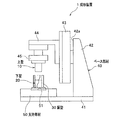
ガラスレンズ等の光学部品を製造するための成形装置としては、例えば、図5に示すように、下端面にキャビティ面111を有する上型110と、上端面にキャビティ面121を有する下型120とを閉じてキャビティ(図示せず)を形成し、このキャビティ内で材料を押圧して、レンズ等の製品を成形する成形装置100がある。
As a molding apparatus for manufacturing an optical component such as a glass lens, for example, as shown in FIG. 5, an
前記した従来の成形装置100において、上型110と下型120を組み付けるときには、まず、ベース部材の基板141に定着された下型120に、筒状の胴型130の下部を外嵌させ、その後、上下方向に移動可能なスライダ144に支持された上型110を、胴型130の上部に挿入することにより、上型110と下型120の芯合わせを行っている(例えば、特許文献1参照)。
なお、上型110の下端面の外周縁にはテーパ面113が形成され、胴型130の上側開口部の内周縁にはテーパ面131が形成されている。
In the
A
また、上型110を保持するチャック部材145とスライダ144の間には、ゴム材やばね等の弾性部材146が介設されており、弾性部材146が撓むことにより、上型110は水平方向に移動可能となっている。そして、上型110と下型120を組み付けるときに、上型110と下型120の軸心がずれている場合には、上型110のテーパ面113と、胴型130のテーパ面131とが当接し、上型110が胴型130のテーパ面131に倣って移動することにより、上型110の位置が調整され、上型110と下型120の芯合わせが行われた状態となる。
Further, an
しかしながら、前記した従来の成形装置100では、上型110が胴型130に倣って移動するときに、上型110には弾性部材146の撓みによる反力が生じることになる。これにより、上型110と胴型130の接触圧が大きくなり、上型110が胴型130にかじってしまうため、上型110に磨耗や損傷が生じてしまうという問題がある。
However, in the
そこで、本発明では、前記した問題を解決し、二体の金型の芯合わせを行いながら組み付けるときに、金型の磨耗及び損傷を防ぐことができる成形装置及び金型の組み付け方法を提供することを課題とする。 Therefore, the present invention solves the above-described problems and provides a molding apparatus and a mold assembling method capable of preventing the mold from being worn and damaged when the two molds are assembled while being aligned. This is the issue.
前記課題を解決するため、本発明は、成形装置であって、型閉時にキャビティを形成し、キャビティ内で製品を成形するように構成された第1の金型及び第2の金型と、第1の金型及び第2の金型に跨って外嵌されることにより、第1の金型と第2の金型の芯合わせを行う胴型と、を備え、第2の金型は、支持部材に支持されており、支持部材は、第2の金型を浮上状態で支持可能であることを特徴としている。 In order to solve the above-mentioned problems, the present invention is a molding apparatus, wherein a first mold and a second mold configured to form a cavity when the mold is closed and mold a product in the cavity, The first mold and the second mold are externally fitted to each other, thereby including a first mold and a body mold for aligning the second mold, and the second mold is The support member is supported by the support member, and the support member can support the second mold in a floating state.
この構成によれば、胴型が外嵌された第2の金型に対して、第1の金型を組み付けるときに、第2の金型を浮上させることにより、胴型及び第2の金型は、第1の金型に倣って移動することになる。これにより、胴型及び第2の金型は、第1の金型に対して位置が調整され、第1の金型と第2の金型の芯合わせが行われる。
また、胴型が外嵌された第1の金型に対して、第2の金型を組み付けるときに、第2の金型を浮上させることにより、第2の金型は、胴型に倣って移動し、胴型に対して位置が調整され、第1の金型と第2の金型の芯合わせが行われる。
そして、浮上させた第2の金型には反力が生じないため、第1の金型又は第2の金型と胴型との接触圧が小さくなり、金型の磨耗や損傷を防ぐことができる。
According to this configuration, when assembling the first mold with respect to the second mold with the body mold fitted outside, the second mold is levitated so that the trunk mold and the second mold are floated. The mold moves following the first mold. Thereby, the positions of the body mold and the second mold are adjusted with respect to the first mold, and the first mold and the second mold are aligned.
In addition, when the second mold is assembled to the first mold with the body mold fitted outside, the second mold follows the body mold by floating the second mold. The position is adjusted with respect to the body mold, and the first mold and the second mold are aligned.
Then, since no reaction force is generated in the second mold that has been levitated, the contact pressure between the first mold or the second mold and the body mold is reduced, thereby preventing the mold from being worn or damaged. Can do.
前記した成形装置において、支持部材は、第2の金型を浮上状態及び定着状態で支持可能であるように構成することができる。 In the molding apparatus described above, the support member can be configured to support the second mold in the floating state and the fixed state.
この構成によれば、第2の金型を浮上させて、第1の金型と第2の金型を組み付けた後に、支持部材とともに第1の金型及び第2の金型を搬送する場合には、第2の金型を支持部材に定着させることにより、第1の金型及び第2の金型を安定させて搬送することができる。 According to this configuration, after the second mold is levitated and the first mold and the second mold are assembled, the first mold and the second mold are transported together with the support member. In this case, the first mold and the second mold can be stably conveyed by fixing the second mold to the support member.
前記した成形装置において、支持部材は、第2の金型と支持部材の間に流体を供給することにより、第2の金型を浮上状態で支持するように構成することができる。
さらに、前記した成形装置において、第2の金型は、保持部材を介して支持部材に支持されており、支持部材は、支持部材と保持部材の間に流体を供給することにより、第2の金型を浮上状態で支持するように構成することができる。
In the molding apparatus described above, the support member can be configured to support the second mold in a floating state by supplying a fluid between the second mold and the support member.
Furthermore, in the molding apparatus described above, the second mold is supported by the support member via the holding member, and the support member supplies the fluid between the support member and the holding member, thereby The mold can be configured to be supported in a floating state.
このように、流体の供給によって第2の金型を浮上させることにより、支持部材を簡易な構成にすることができるため、成形装置の製造コストを低減することができる。 Thus, since the support member can be made simple by raising the second mold by supplying the fluid, the manufacturing cost of the molding apparatus can be reduced.
前記した成形装置を用いた金型の組み付け方法であって、第2の金型を支持部材から浮上させる段階と、第1の金型及び第2の金型に跨って胴型を外嵌させることにより、第1の金型と第2の金型の芯合わせを行う段階と、を含むことを特徴としている。 A method of assembling a mold using the molding apparatus described above, the step of levitating the second mold from the support member, and externally fitting the body mold across the first mold and the second mold In this way, the method includes the step of aligning the first mold and the second mold.
この構成によれば、第1の金型と第2の金型に跨って胴型を外嵌するときに、第2の金型を浮上させることにより、第2の金型が第1の金型や胴型に倣って移動することになる。このとき、浮上させた第2の金型には反力が生じないため、第1の金型又は第2の金型と胴型との接触圧が小さくなり、金型の磨耗や損傷を防ぐことができる。 According to this configuration, when the body mold is externally fitted across the first mold and the second mold, the second mold is levitated so that the second mold becomes the first mold. It moves following the mold and body mold. At this time, no reaction force is generated in the levitated second mold, so that the contact pressure between the first mold or the second mold and the body mold is reduced to prevent wear and damage of the mold. be able to.
本発明によれば、第1の金型と第2の金型に跨って胴型を外嵌するときに、第2の金型を浮上させることにより、第2の金型には反力が生じないため、第1の金型又は第2の金型と胴型との接触圧が小さくなり、金型の磨耗や損傷を防ぐことができる。 According to the present invention, when the body mold is fitted over the first mold and the second mold, the second mold is levitated so that the reaction force is exerted on the second mold. Since it does not occur, the contact pressure between the first mold or the second mold and the body mold is reduced, and wear and damage of the mold can be prevented.
次に、本発明の実施形態について、適宜図面を参照しながら詳細に説明する。
以下の実施形態では、本発明の成形装置及び金型の組み付け方法をガラス光学レンズ(以下、単に「レンズ」という。)の製造工程に適用した場合について説明する。
なお、各実施形態の説明において、同一の構成要素に関しては同一の符号を付し、重複した説明は省略するものとする。
Next, embodiments of the present invention will be described in detail with reference to the drawings as appropriate.
In the following embodiments, a case where the molding apparatus and the mold assembling method of the present invention are applied to a manufacturing process of a glass optical lens (hereinafter simply referred to as “lens”) will be described.
In the description of each embodiment, the same constituent elements are denoted by the same reference numerals, and redundant descriptions are omitted.
<第1実施形態>
まず、第1実施形態の成形装置の構成を説明した後に、この成形装置を用いた金型の組み付け方法について説明する。
図1は、第1実施形態の成形装置を示した側面図である。図2は、第1実施形態の成形装置を示した図で、(a)は成形装置の部分拡大側断面図、(b)は支持部材の平面図である。図3は、第1実施形態の成形装置によって金型を組み付ける態様を示した図で、(a)は下型を支持部材から浮上させた状態の側断面図、(b)は上型を胴型に挿入した状態の側断面図、(c)は上型と下型を支持部材に定着させた状態の側断面図である。
<First Embodiment>
First, after describing the configuration of the molding apparatus according to the first embodiment, a method for assembling a mold using the molding apparatus will be described.
FIG. 1 is a side view showing the molding apparatus of the first embodiment. 2A and 2B are views showing the molding apparatus of the first embodiment, in which FIG. 2A is a partially enlarged side sectional view of the molding apparatus, and FIG. 2B is a plan view of a support member. FIGS. 3A and 3B are views showing a manner in which the mold is assembled by the molding apparatus according to the first embodiment. FIG. 3A is a side cross-sectional view of a state where the lower mold is levitated from the support member, and FIG. FIG. 4C is a side sectional view of the state in which the upper mold and the lower mold are fixed to the support member.
[成形装置の構成]
成形装置1は、図1に示すように、型閉時にキャビティ(図示せず)を形成し、このキャビティ内でレンズを成形するように構成された上型10(特許請求の範囲における「第1の金型」)及び下型20(特許請求の範囲における「第2の金型」)と、上型10及び下型20に跨って外嵌されることにより、上型10及び下型20の芯合わせを行う胴型30と、上型10を移動させるためのスライダ44及び下型20を支持する支持部材50が取り付けられたベース部材40と、から構成されている。
[Configuration of molding equipment]
As shown in FIG. 1, the molding apparatus 1 forms a cavity (not shown) when the mold is closed, and an
なお、この成形装置1は、上型10と下型20の間に材料を投入して組み付ける工程を行うための装置であり、この成形装置1によって組み付けられた上型10及び下型20は、支持部材50とともに、他の成形装置に移送されるように構成されている。そして、他の成形装置において、上型10と下型20を加熱した後に、上型10と下型20を閉じてキャビティ内で材料を押圧することにより、レンズの成形が行われることになる。
In addition, this shaping | molding apparatus 1 is an apparatus for throwing material between the upper mold |
(上型及び下型の構成)
上型10及び下型20は、図2(a)に示すように、円柱状に形成された金属性の部材であり、上下に対峙した状態で配置されている。
上型10では、下端面にキャビティ面11が形成されており、この下端面の外周縁にはテーパ面13が形成されている。また、上型10の上端部の外周にはフランジ部12が形成されている。
また、上型10は、後記するベース部材40(図1参照)のスライダ44によって、型開閉方向(上下方向)に移動可能となっている。具体的には、上型10は、上下方向に移動可能なスライダ44にチャック部材45を介して取り付けられている。
(Configuration of upper mold and lower mold)
The upper mold |
In the
The
下型20では、上端面にキャビティ面21が形成されており、下端部の外周にはフランジ部22が形成されている。この下型20は、後記するベース部材40(図1参照)に取り付けられた支持部材50の上面に取り付けられている。
In the
(支持部材の構成)
支持部材50は、図1に示すように、後記するベース部材40の基板41の上面に取り付けられた直方体の部材である。支持部材50の上面には、下型20が載置される凹部51が形成されている。
この凹部51は、図2(a)及び(b)に示すように、平面視で円形状となっており、その外径は下型20のフランジ部22の外径よりも大きく形成されている。具体的には、下型20の平面中心と凹部51の中心とを一致させた状態で、下型20を凹部51内に載置したときに、下型20のフランジ部22の外周面と、凹部51の内周面との隙間が、後記する胴型30の上側開口部の内周縁に形成されたテーパ面31の幅よりも大きくなるように設定されている。また、凹部51の深さは、下型20のフランジ部22の高さの略半分となっている。
(Configuration of support member)
As shown in FIG. 1, the
As shown in FIGS. 2A and 2B, the
また、支持部材50の内部には、一端が凹部51の底面の中心に開口され、他端は支持部材50の外部に設けられたエア吸込み装置(図示せず)に接続された負圧流路52が設けられている。
さらに、支持部材50の内部には、一端が凹部51の底面に開口され、他端は支持部材50の外部に設けられたエアコンプレッサ(図示せず)に接続された正圧流路53が設けられている。この実施形態では、八つの正圧流路53・・・が負圧流路52に沿って設けられており、各正圧流路53・・・の一端は、凹部51の底面において、負圧流路52の開口部の周囲に均等間隔に開口されている。
Further, one end of the
Further, inside the
そして、凹部51の底面上に下型20を載置し、各正圧流路53・・・に接続されたエアコンプレッサを作動させた場合には、各正圧流路53・・・の開口部からエア(流体)が噴出し、下型20と支持部材50の間にエアが供給されることにより、下型20が支持部材50から浮上した状態となる。なお、エアの噴出圧は、浮上させた下型20が凹部51内から外れない程度に設定されている。
また、エアコンプレッサの作動を停止し、負圧流路52に接続されたエア吸込み装置を作動させた場合には、負圧流路52の開口部からエア(流体)が吸い出され、下型20と支持部材50の間からエアが排出されることにより、下型20が支持部材50に吸着(定着)した状態となる。
このように、支持部材50では、下型20を浮上状態及び定着状態で支持可能となっている。
And when the lower mold |
When the operation of the air compressor is stopped and the air suction device connected to the
As described above, the
(ベース部材の構成)
ベース部材40は、図1に示すように、平板状の基板41と、この基板41の上面に立設された支柱42と、支柱42に形成された鉛直面42aに取り付けられ、上下方向に延設されたガイドレール43と、ガイドレール43に沿って上下方向に移動可能なスライダ44と、を備えている。また、スライダ44には、チャック部材45が取り付けられており、チャック部材45の下面には、上型10のフランジ部12が保持されている。なお、チャック部材45が上型10を保持する構成は限定されるものではなく、エアの吸引や磁力等を用いて上型10を吸着する構成や、上型10を爪等の部材で挟み込む構成など、公知の技術を用いている。
(Configuration of base member)
As shown in FIG. 1, the
(胴型の構成)
胴型30は、図3(b)に示すように、上型10及び下型20に跨って外嵌されることにより、上型10及び下型20の芯合わせを行う円筒状の部材であり、胴型30の上部には上型10が挿入され、胴型30の下部には下型20が挿入されるように構成されている。また、胴型30の上側開口部の内周縁にはテーパ面31が形成されている。
(Body type configuration)
As shown in FIG. 3B, the
[成形装置を用いた金型の組み付け方法]
次に、第1実施形態の成形装置1を用いた金型の組み付け方法について説明する。
まず、図2(a)に示すように、支持部材50の凹部51の底面に下型20を載置し、下型20に胴型30の下部を外嵌させる。また、下型20の上端面に形成されたキャビティ面21に材料Gを載置する。一方、上型10はチャック部材45を介してスライダ44に取り付ける。
[Die Assembling Method Using Molding Equipment]
Next, a method for assembling a mold using the molding apparatus 1 of the first embodiment will be described.
First, as shown in FIG. 2A, the
また、図3(a)に示すように、各正圧流路53・・・に接続されたエアコンプレッサ(図示せず)を作動させ、各正圧流路53・・・の開口部からエアを噴出させることにより、下型20と支持部材50の間にエアを供給して、下型20を支持部材50から浮上させる。
Further, as shown in FIG. 3A, an air compressor (not shown) connected to each
続いて、スライダ44を下降させることにより、上型10を型閉方向に移動させる。そして、図3(a)のように、上型10と下型20の軸心がずれている場合には、上型10のテーパ面13と胴型30のテーパ面31とが当接することになる。
このとき、胴型30が外嵌された下型20は、支持部材50から浮上しており、さらに、下型20のフランジ部22の外周面と凹部51の内周面との間には、胴型30のテーパ面31の幅よりも大きな隙間が形成されているため、胴型30及び下型20は、上型10のテーパ面13に倣って移動し、図3(b)に示すように、胴型30及び下型20の位置が調整され、上型10が胴型30の上部に挿入される。
このように、胴型30を上型10及び下型20に跨って外嵌させることにより、上型10と下型20の芯合わせが行われるため、上型10と下型20を高精度に組み付けることができる。
Subsequently, the
At this time, the
As described above, since the
さらに、図3(c)に示すように、上型10と下型20を組み付けた後に、エアコンプレッサの作動を停止し、負圧流路52に接続されたエア吸込み装置(図示せず)を作動させることにより、下型20と支持部材50の間からエアを排出して、下型20を支持部材50に吸着させる。これにより、支持部材50とともに上型10及び下型20を搬送するときに、上型10及び下型20を安定させて搬送することができる。
Further, as shown in FIG. 3C, after the
[成形装置の作用効果]
図1に示す成形装置1では、胴型30が外嵌された下型20に対して、上型10を組み付けるときに、図3(a)に示すように、下型20を支持部材50から浮上させることにより、下型20には反力が生じないため、上型10と胴型30の接触圧が小さくなり、上型10の磨耗や損傷を防ぐことができる。そして、図3(c)に示すように、上型10と下型20を組み付けた後に、下型20を支持部材50に定着させることにより、支持部材50とともに、上型10及び下型20を安定させて搬送することができる。
[Functional effects of molding equipment]
In the molding apparatus 1 shown in FIG. 1, when the
また、図3(a)に示すように、下型20と支持部材50の間にエアを供給して、下型20を支持部材50から浮上させ、図3(c)に示すように、下型20と支持部材50の間からエアを排出して、下型20を支持部材50に定着させている。このように、エアの供給及び排出によって、下型20を支持部材50に対して浮上及び定着させているため、支持部材50を簡易な構成にすることができ、成形装置1の製造コストを低減することができる。
Further, as shown in FIG. 3A, air is supplied between the
<第2実施形態>
次に、第2実施形態の成形装置及び金型の組み付け方法について説明する。
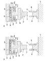
図4は、第2実施形態の成形装置を示した図で、(a)は上型を支持部材に定着させた状態の側断面図、(b)は上型を支持部材から浮上させた状態の側断面図である。
第2実施形態の成形装置では、図4に示すように、スライダ44に取り付けられた支持部材60が、上型10(特許請求の範囲における「第2の金型」)を浮上状態及び定着状態で支持するように構成されている。具体的には、上型10はチャック部材45´(特許請求の範囲における「保持部材」)に保持されており、上型10はチャック部材45´を介して支持部材60に支持されている。
また、下型20(特許請求の範囲における「第1の金型」)は、ベース部材の基板41の上面に定着されている。
Second Embodiment
Next, the molding apparatus and mold assembling method of the second embodiment will be described.
4A and 4B are diagrams showing a molding apparatus according to the second embodiment, in which FIG. 4A is a side sectional view showing a state where the upper mold is fixed to the support member, and FIG. 4B is a state where the upper mold is levitated from the support member. FIG.
In the molding apparatus according to the second embodiment, as shown in FIG. 4, the
The lower mold 20 (“first mold” in the claims) is fixed on the upper surface of the
第2実施形態の支持部材60は、図4(a)に示すように、内部空間61を有する中空の箱体であり、その下板には円形の貫通穴61aが形成され、この貫通穴61aを通じて、チャック部材45´の上部が内部空間61内に配設されている。また、チャック部材45´の上端部には円板状のフランジ部45aが形成されており、このフランジ部45aは貫通穴61aよりも拡径されている。
As shown in FIG. 4A, the
また、支持部材60には、一端が内部空間60の上面61bの中心に開口され、他端は支持部材60の外部に設けられたエア吸込み装置(図示せず)に接続された負圧流路62が設けられている。
さらに、支持部材60の内部には、一端が内部空間60の上面61b又は下面61cに開口され、他端は支持部材60の外部に設けられたエアコンプレッサ(図示せず)に接続された複数の正圧流路63が設けられている。
The
Further, inside the
そして、支持部材60では、図4(b)に示すように、チャック部材45´のフランジ部45aと、内部空間61の上面61b及び下面61cとの間に、各正圧流路63・・・からエアを供給し、供給したエアによってチャック部材45´を内部空間61内で浮上させることにより、上型10を浮上状態で支持することができる。
また、支持部材60では、図4(a)に示すように、各正圧流路63・・・からのエアの供給を停止するとともに、チャック部材45´のフランジ部45aと、内部空間61の上面61bとの間から、負圧流路62によってエアを排出し、チャック部材45´を内部空間61の上面61bに吸着(定着)させることにより、上型10を定着状態で支持することができる。
なお、上型10を浮上状態及び定着状態で支持する支持部材60は、各種公知の技術を用いて構成することができ、その構成は限定されるものではない。
And in the
Further, in the
The
第2実施形態の成形装置を用いて、上型10と下型20を組み付けるときには、まず、図4(b)に示すように、内部空間61内でチャック部材45´と支持部材60の間にエアを供給して、チャック部材45´を支持部材60から浮上させ、上型10が浮上状態で支持部材60に支持された状態にする。この状態で上型10を下降させて下型20に組み付ける。上型10と下型20の軸心がずれている場合には、上型10のテーパ面13が胴型30のテーパ面31に当接し、浮上させた上型10が胴型30のテーパ面31に倣って移動することになり、上型10の位置が調整され、上型10と下型20の芯合わせが行われる。
このとき、浮上させた上型10には反力が生じないため、上型10と胴型30の接触圧が小さくなり、上型10の磨耗や損傷を防ぐことができる。
When assembling the
At this time, no reaction force is generated in the levitated
[他の実施形態]
以上、本発明の実施形態について図面を参照して詳細に説明したが、本発明は前記した各実施形態に限定されるものではなく、本発明の主旨を逸脱しない範囲で適宜変更が可能である。
例えば、前記実施形態の成形装置1(図1参照)は、上型10と下型20を組み付けるための装置であり、この成形装置1によって組み付けられた上型10及び下型20は、材料の押圧するための成形装置に搬送されるように構成されているが、前記実施形態の成形装置1において、上型10と下型20の組み付け、及びレンズの成形の両方を行うように構成することもできる。
[Other Embodiments]
As mentioned above, although embodiment of this invention was described in detail with reference to drawings, this invention is not limited to each above-mentioned embodiment, In the range which does not deviate from the main point of this invention, it can change suitably. .
For example, the molding apparatus 1 (see FIG. 1) of the above embodiment is an apparatus for assembling the
また、前記各実施形態では、図3又は図4に示すように、支持部材50,60に対してエアを供給及び排出することにより、上型10又は下型20を浮上状態及び定着状態で支持するように構成されているが、上型10又は下型20を浮上及び定着させる構成は限定されるものではなく、磁力や液体等を用いることもできる。さらに、上型10及び下型20が支持部材50上で安定するのであれば、負圧流路52を設けなくてもよい。
Further, in each of the above embodiments, as shown in FIG. 3 or FIG. 4, the
また、前記各実施形態では、図2又は図4に示すように、円筒状の胴型30を用いて上型10と下型20の芯合わせを行っているが、その構成は限定されるものではなく、例えば、胴型を複数に分割し、この分割された部材を、上型10及び下型20の外周面の少なくとも三方向に当接させることにより、上型10と下型20の芯合わせが行うこともできる。
Moreover, in each said embodiment, as shown in FIG. 2 or FIG. 4, although the center alignment of the upper mold |
1 成形装置
10 上型
11 キャビティ面(上型)
20 下型
21 キャビティ面(下型)
30 胴型
40 ベース部材
44 スライダ
45 チャック部材
50 支持部材
51 凹部
52 負圧流路
53 正圧流路
1
20
30
Claims (5)
前記上型のキャビティ面が形成された端面の外周縁あるいは前記胴型の前記上型が挿入される端面の内周縁の少なくとも一方に設けられたテーパ面と、
前記上型又は下型の一方が前記型閉じ方向と直交する面内で移動自在に支持されるとともに、支持された前記上型又は下型の一方を浮上させる流体が吐出される正圧流路を有する支持部材と、
を備え、
前記一方の上型又は下型が前記流体によって浮上した状態で前記型閉じが行われるとともに、前記型閉じ時に前記一方の上型又は下型が前記テーパ面に倣って前記型閉じ方向と直交する面内で移動して、前記上型と下型の芯合わせが行われることを特徴とする成形装置。 A molding apparatus having an upper mold and a lower mold configured to form a cavity when the mold is closed and to mold a product in the cavity, and a body mold that is externally fitted across the upper mold and the lower mold. There,
A tapered surface provided on at least one of an outer peripheral edge of the end face on which the cavity surface of the upper mold is formed or an inner peripheral edge of the end face into which the upper mold of the trunk mold is inserted;
Positive flow paths where one of the upper mold or the lower mold while being movably supported in a plane perpendicular to the mold closing direction, the fluid to one of the upper floating support by the upper mold or lower mold is discharged A support member having
With
The mold closing is performed in a state where the one upper mold or the lower mold is floated by the fluid, and when the mold is closed, the one upper mold or the lower mold follows the taper surface and is orthogonal to the mold closing direction. A molding apparatus characterized in that the upper mold and the lower mold are aligned by moving in a plane.
Priority Applications (5)
| Application Number | Priority Date | Filing Date | Title |
|---|---|---|---|
| JP2006163691A JP4841323B2 (en) | 2006-06-13 | 2006-06-13 | Molding equipment |
| KR1020070054415A KR100917643B1 (en) | 2006-06-13 | 2007-06-04 | Molding device and method for setting up mold |
| CN2007101099620A CN101088945B (en) | 2006-06-13 | 2007-06-11 | Molding device and method for setting up mold |
| US11/808,681 US7950253B2 (en) | 2006-06-13 | 2007-06-12 | Molding device and method for setting up mold |
| TW096121357A TW200800816A (en) | 2006-06-13 | 2007-06-13 | Molding device and method for setting up mold |
Applications Claiming Priority (1)
| Application Number | Priority Date | Filing Date | Title |
|---|---|---|---|
| JP2006163691A JP4841323B2 (en) | 2006-06-13 | 2006-06-13 | Molding equipment |
Publications (3)
| Publication Number | Publication Date |
|---|---|
| JP2007331963A JP2007331963A (en) | 2007-12-27 |
| JP2007331963A5 JP2007331963A5 (en) | 2009-05-21 |
| JP4841323B2 true JP4841323B2 (en) | 2011-12-21 |
Family
ID=38876961
Family Applications (1)
| Application Number | Title | Priority Date | Filing Date |
|---|---|---|---|
| JP2006163691A Expired - Fee Related JP4841323B2 (en) | 2006-06-13 | 2006-06-13 | Molding equipment |
Country Status (5)
| Country | Link |
|---|---|
| US (1) | US7950253B2 (en) |
| JP (1) | JP4841323B2 (en) |
| KR (1) | KR100917643B1 (en) |
| CN (1) | CN101088945B (en) |
| TW (1) | TW200800816A (en) |
Families Citing this family (9)
| Publication number | Priority date | Publication date | Assignee | Title |
|---|---|---|---|---|
| KR101049366B1 (en) * | 2006-01-30 | 2011-07-13 | 도시바 기카이 가부시키가이샤 | Mold for Glass Element Molding |
| DK2242522T3 (en) * | 2008-01-08 | 2012-06-18 | Bluesky Medical Group Inc | Wound treatment with uninterrupted variable pressure and methods for controlling it |
| TW201034829A (en) * | 2009-03-27 | 2010-10-01 | Kinik Co | Mold of optical lens |
| JP6305810B2 (en) * | 2014-03-31 | 2018-04-04 | キヤノンメディカルシステムズ株式会社 | Medical diagnostic imaging equipment |
| DE102016119636B3 (en) * | 2016-10-14 | 2018-02-08 | Carl Zeiss Smart Optics Gmbh | Molding tool and use of the same |
| KR101846209B1 (en) | 2017-04-25 | 2018-04-06 | 주식회사 인터로조 | Apparatus For Molding Of Contact Lens |
| KR101846196B1 (en) | 2017-04-25 | 2018-04-09 | 주식회사 인터로조 | Manufacturing Method Of Contact Lens Using Assembly Device For Molding Of Contact Lens |
| TWM569757U (en) * | 2018-06-20 | 2018-11-11 | 欣弘元科技股份有限公司 | Glass forming furnace |
| CN111908774B (en) * | 2019-05-10 | 2022-07-22 | 赵崇礼 | Lens array mold apparatus |
Family Cites Families (16)
| Publication number | Priority date | Publication date | Assignee | Title |
|---|---|---|---|---|
| JPS5955711A (en) | 1982-09-24 | 1984-03-30 | Uchiyama Mfg Corp | Structure of main forming dies |
| US5104590A (en) * | 1988-10-26 | 1992-04-14 | Wright Medical, Inc. | Fabrication of an intraocular lens |
| JP3103243B2 (en) * | 1992-06-02 | 2000-10-30 | 住友重機械プラスチックマシナリー株式会社 | Glass compression molding machine and its processing room |
| JP3224472B2 (en) | 1993-05-26 | 2001-10-29 | キヤノン株式会社 | Optical lens and mold for molding the same |
| JP3588812B2 (en) * | 1994-01-27 | 2004-11-17 | 旭硝子株式会社 | Press forming equipment |
| JP3501580B2 (en) * | 1995-04-20 | 2004-03-02 | キヤノン株式会社 | Optical element molding method and molding apparatus |
| JP3974200B2 (en) * | 1995-11-09 | 2007-09-12 | Hoya株式会社 | Glass optical element molding method |
| JPH09202625A (en) * | 1996-01-24 | 1997-08-05 | Asahi Glass Co Ltd | Mold positioning device and mold positioning |
| JP2000159528A (en) | 1998-11-24 | 2000-06-13 | Matsushita Electric Ind Co Ltd | Forming apparatus of optical element and production method |
| JP3890929B2 (en) * | 2001-08-03 | 2007-03-07 | 松下電器産業株式会社 | Optical element molding method |
| JP4395704B2 (en) * | 2002-05-17 | 2010-01-13 | コニカミノルタホールディングス株式会社 | Molding equipment |
| US7108812B2 (en) * | 2002-05-17 | 2006-09-19 | Konica Corporation | Forming die unit adjusting method and forming apparatus |
| JP3924232B2 (en) * | 2002-10-09 | 2007-06-06 | Towa株式会社 | Resin mold and resin molding method |
| TWI246457B (en) * | 2002-12-24 | 2006-01-01 | Ind Tech Res Inst | Hot embossing auto-leveling apparatus and method |
| JP2005170751A (en) | 2003-12-12 | 2005-06-30 | Matsushita Electric Ind Co Ltd | Method and apparatus for forming glass lens |
| JP4312588B2 (en) * | 2003-12-22 | 2009-08-12 | 住友重機械工業株式会社 | Press forming equipment |
-
2006
- 2006-06-13 JP JP2006163691A patent/JP4841323B2/en not_active Expired - Fee Related
-
2007
- 2007-06-04 KR KR1020070054415A patent/KR100917643B1/en not_active IP Right Cessation
- 2007-06-11 CN CN2007101099620A patent/CN101088945B/en not_active Expired - Fee Related
- 2007-06-12 US US11/808,681 patent/US7950253B2/en not_active Expired - Fee Related
- 2007-06-13 TW TW096121357A patent/TW200800816A/en not_active IP Right Cessation
Also Published As
| Publication number | Publication date |
|---|---|
| KR100917643B1 (en) | 2009-09-17 |
| JP2007331963A (en) | 2007-12-27 |
| CN101088945B (en) | 2010-12-15 |
| CN101088945A (en) | 2007-12-19 |
| KR20070118954A (en) | 2007-12-18 |
| TWI361173B (en) | 2012-04-01 |
| US7950253B2 (en) | 2011-05-31 |
| TW200800816A (en) | 2008-01-01 |
| US20080003324A1 (en) | 2008-01-03 |
Similar Documents
| Publication | Publication Date | Title |
|---|---|---|
| JP4841323B2 (en) | Molding equipment | |
| TWI437320B (en) | A substrate mounting apparatus, and a substrate mounting method using the same | |
| JP5992552B2 (en) | Ejecting device | |
| JP4613800B2 (en) | Levitation device and transfer device | |
| KR101627906B1 (en) | Apparatus for ejecting a die | |
| JPWO2005049287A1 (en) | Vacuum suction head, vacuum suction device and table using the vacuum suction head | |
| JP2005203088A (en) | Workpiece handler and alignment assembly | |
| US20070252292A1 (en) | Mold unit for manufacturing plastic edged glass shelf, method for manufacturing plastic edged glass shelf using the same, and plastic edged glass shelf manufactured thereby | |
| JP2017200712A (en) | Suction unit, plate-like member transportation unit, resin encapsulation device, plate-like member transportation method and resin encapsulation method | |
| KR20160068201A (en) | Apparatus for ejecting a die | |
| JP2006276669A (en) | Pressure-sensitive adhesive chuck device and substrate sticking machine equipped with the same | |
| JP4924316B2 (en) | Semiconductor manufacturing apparatus and semiconductor manufacturing method | |
| KR20210031606A (en) | Suction holder and ring frame holding mechanism | |
| JP3859481B2 (en) | Flexible plate take-out device and take-out method | |
| JP2013006261A (en) | Demolding device | |
| KR20030076602A (en) | Method and device for assembling substrates | |
| KR101233580B1 (en) | A Substrate Holder Attaching and Detaching Device | |
| CN110703469B (en) | Substrate assembling device and substrate assembling method | |
| KR101515710B1 (en) | Apparatus for supplying collets | |
| JP7026862B1 (en) | Elastic sheet punching device and elastic sheet punching system | |
| KR102169007B1 (en) | Contact lens manufacturing apparatus | |
| JP7347869B2 (en) | Board assembly equipment and board assembly method | |
| US20100196527A1 (en) | Imprinting device | |
| KR102455166B1 (en) | Vacuum chuck and driving method of vacuum chuck | |
| KR102161520B1 (en) | Apparatus for ejecting a die |
Legal Events
| Date | Code | Title | Description |
|---|---|---|---|
| A521 | Written amendment |
Free format text: JAPANESE INTERMEDIATE CODE: A523 Effective date: 20090407 |
|
| A621 | Written request for application examination |
Free format text: JAPANESE INTERMEDIATE CODE: A621 Effective date: 20090407 |
|
| A711 | Notification of change in applicant |
Free format text: JAPANESE INTERMEDIATE CODE: A711 Effective date: 20100621 |
|
| A977 | Report on retrieval |
Free format text: JAPANESE INTERMEDIATE CODE: A971007 Effective date: 20101130 |
|
| A131 | Notification of reasons for refusal |
Free format text: JAPANESE INTERMEDIATE CODE: A131 Effective date: 20101208 |
|
| A521 | Written amendment |
Free format text: JAPANESE INTERMEDIATE CODE: A523 Effective date: 20110119 |
|
| A131 | Notification of reasons for refusal |
Free format text: JAPANESE INTERMEDIATE CODE: A131 Effective date: 20110727 |
|
| A521 | Written amendment |
Free format text: JAPANESE INTERMEDIATE CODE: A523 Effective date: 20110819 |
|
| TRDD | Decision of grant or rejection written | ||
| A01 | Written decision to grant a patent or to grant a registration (utility model) |
Free format text: JAPANESE INTERMEDIATE CODE: A01 Effective date: 20110907 |
|
| A01 | Written decision to grant a patent or to grant a registration (utility model) |
Free format text: JAPANESE INTERMEDIATE CODE: A01 |
|
| A61 | First payment of annual fees (during grant procedure) |
Free format text: JAPANESE INTERMEDIATE CODE: A61 Effective date: 20111004 |
|
| R150 | Certificate of patent or registration of utility model |
Free format text: JAPANESE INTERMEDIATE CODE: R150 |
|
| FPAY | Renewal fee payment (event date is renewal date of database) |
Free format text: PAYMENT UNTIL: 20141014 Year of fee payment: 3 |
|
| R250 | Receipt of annual fees |
Free format text: JAPANESE INTERMEDIATE CODE: R250 |
|
| R250 | Receipt of annual fees |
Free format text: JAPANESE INTERMEDIATE CODE: R250 |
|
| R250 | Receipt of annual fees |
Free format text: JAPANESE INTERMEDIATE CODE: R250 |
|
| R250 | Receipt of annual fees |
Free format text: JAPANESE INTERMEDIATE CODE: R250 |
|
| LAPS | Cancellation because of no payment of annual fees |