JP4840552B2 - Ozone gas monitoring device - Google Patents
Ozone gas monitoring device Download PDFInfo
- Publication number
- JP4840552B2 JP4840552B2 JP2001200666A JP2001200666A JP4840552B2 JP 4840552 B2 JP4840552 B2 JP 4840552B2 JP 2001200666 A JP2001200666 A JP 2001200666A JP 2001200666 A JP2001200666 A JP 2001200666A JP 4840552 B2 JP4840552 B2 JP 4840552B2
- Authority
- JP
- Japan
- Prior art keywords
- ozone
- building
- ozone gas
- ozone concentration
- concentration
- Prior art date
- Legal status (The legal status is an assumption and is not a legal conclusion. Google has not performed a legal analysis and makes no representation as to the accuracy of the status listed.)
- Expired - Fee Related
Links
Images

Classifications
-
- Y—GENERAL TAGGING OF NEW TECHNOLOGICAL DEVELOPMENTS; GENERAL TAGGING OF CROSS-SECTIONAL TECHNOLOGIES SPANNING OVER SEVERAL SECTIONS OF THE IPC; TECHNICAL SUBJECTS COVERED BY FORMER USPC CROSS-REFERENCE ART COLLECTIONS [XRACs] AND DIGESTS
- Y02—TECHNOLOGIES OR APPLICATIONS FOR MITIGATION OR ADAPTATION AGAINST CLIMATE CHANGE
- Y02A—TECHNOLOGIES FOR ADAPTATION TO CLIMATE CHANGE
- Y02A50/00—TECHNOLOGIES FOR ADAPTATION TO CLIMATE CHANGE in human health protection, e.g. against extreme weather
- Y02A50/20—Air quality improvement or preservation, e.g. vehicle emission control or emission reduction by using catalytic converters
Landscapes
- Treating Waste Gases (AREA)
- Oxygen, Ozone, And Oxides In General (AREA)
Description
【0001】
【発明の属する技術分野】
本発明は、オゾン発生装置が設備された建屋内におけるオゾン濃度の上昇を防ぐと共に、建屋内から大気中へのオゾンの漏洩を確実に防止するに好適なオゾンガス監視装置に関する。
【0002】
【関連する背景技術】
近時、オゾンの強力な酸化力を利用して液体や気体中の有毒物質を分解したり、殺菌等の環境浄化を行うことが種々試みられている。しかしその使用後に排出される余剰オゾンは低濃度であっても人体に有害であり、また余剰オゾンが大気中に漏れた場合には光化学スモッグの発生要因ともなる。そこで従来では、上述した有毒物質の分解や環境浄化に用いた後の余剰オゾンを活性炭等を用いて分解し、除去するようにしている。
【0003】
【発明が解決しようとする課題】
ところで上述したようにオゾンを積極的に利用する設備機器に限らず、アーク溶接装置等の放電機器も微量なオゾンを発生し、オゾン発生源の1つであると看做し得る。従ってこの種の機器が設備された環境においても、その環境下において発生したオゾンを分解し、除去することが重要である。特にオゾン発生源が建屋内に設備されている場合、その建屋内の空気中に含まれるオゾン濃度が高くなることを未然に防ぎ、更にはその建屋内から大気中へとオゾンが漏洩することを防止することが重要である。
【0004】
本発明はこのような事情を考慮してなされたもので、その目的は、オゾン発生装置が設備された建屋内におけるオゾン濃度の上昇を防ぎ、更にはその建屋内から大気中へのオゾンの漏洩を確実に防止するに好適なオゾンガス監視装置を提供することにある。
【0005】
【課題を解決するための手段】
上述した目的を達成するべく本発明に係るオゾンガス監視装置は、オゾン発生装置が設備された建屋内における空気中のオゾンガスを監視し、建屋内におけるオゾン濃度の上昇を防ぎ、また建屋内から大気中へのオゾンの漏洩を防止するものであって、
上記建屋内の空気を外部に排出するダクト等の排気設備と、
前記建屋内のオゾン濃度を測定するオゾン濃度測定手段と、
このオゾン濃度測定手段により検出される前記建屋内におけるオゾン濃度が、例えば0.1ppm程度として設定された第1の監視値を越えたときに前記オゾン発生装置の運転を停止させると共に警報を発し、前記オゾン濃度が前記第1の監視値よりも高い、例えば1ppm程度として設定された第2の監視値を越えたときには更に前記排気設備の機能を停止させる制御装置と
を具備したことを特徴としている。
【0006】
また本発明に係るオゾンガス監視装置は、更に前記建屋内の空気を吸引して該空気に含まれるオゾンを分解する、例えば活性炭をオゾン分解剤として用いたオゾンガス処理装置を備え、前記制御装置においては、前記オゾン濃度が第1または第2の監視値を越えたときに前記オゾンガス処理装置の運転を起動する自動運転機能を備えることを特徴としている。
【0007】
好ましくは前記第1の監視値は、0.05〜0.15ppmのオゾン濃度として設定され、また前記第2の監視値は、0.2〜10ppmのオゾン濃度として設定される。
【0008】
【発明の実施の形態】
以下、図面を参照して本発明の一実施形態に係るオゾンガス監視装置について説明する。
図1はこの実施形態に係るオゾンガス監視装置の全体的な概略構成図で、1はオゾン発生装置2が設備された建屋である。この建屋1には排気ダクト3が配設されており、この排気ダクト3を介して建屋1内の空気が屋外に排出されるようになっている。特にこの排気ダクト3には排気ファン(換気ファン)4が組み込まれており、この排気ファン4の作動により建屋1内の空気が排気ダクト3を介して強制的に屋外に排出されるようになっている。
【0009】
また建屋1内には、例えばアルミナシリカゲルに活性炭を混合してタブレットまたは粒状に成形したオゾン分解剤をフィルタとして用いたオゾンガス処理装置5が設けられている。このオゾンガス処理装置5は送風機6により建屋1内の空気を吸引し、上記オゾン分解剤に接触させることで、例えば
C + 2O3 = CO2 + 2O2
として該空気中に含まれるオゾンを分解するもので、建屋1内の空気を浄化する循環式のオゾン除去設備としての役割を担う。このオゾンガス処理装置5は、手動により運転制御されたり、或いは後述するように建屋1内のオゾン濃度に応じて自動運転制御される。
【0010】
ところで前記建屋1には、該建屋1内のオゾン濃度を計測するためのオゾンセンサ7が設けられている。このオゾンセンサ7は、例えば電解液相と気相とに接触させた3つの電極(作用電極,照合電極,対極)を備えたもので、オゾン濃度測定器8により駆動される。上記オゾンセンサ7は、その作用電極に近付くオゾン(O3)により
O3 + 2e- → O2 + O2-
なる反応を生じさせると共に、空気中の酸素を吸着した対極において
O2- + 2H+ → H2O
なる反応を上記作用電極と等価に生起することで、その全体で
O3 + 2e- + 2H+ → O2 + H2O
なる反応を生じさせるものである。前記オゾン濃度測定器8は、このようなオゾンセンサ7における上記O3の酸化反応に伴って前記照合電極に流れる電流を検出することで、前記オゾンセンサ7が設けられた建屋1内のオゾン(O3)濃度を検出するものとなっている。
【0011】
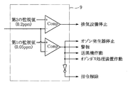
しかして制御装置9は、上記オゾン濃度測定器8にて検出される前記建屋1内のオゾン濃度を監視しており、例えば図2にその機能的な構成を示すように上記オゾン濃度測定器8にて検出されたオゾン濃度を、例えば0.1ppm程度として設定された第1の監視値、およびこの第1の監視値よりも高い、例えば1ppm程度として設定された第2の監視値とそれぞれ比較している。具体的には第1の監視値は、建屋1内の環境に応じて0.05〜0.15ppmのオゾン濃度として設定され、また第2の監視値は0.2〜10ppmのオゾン濃度として設定される。
【0012】
そして制御装置9は、オゾン濃度測定器8にて検出される建屋1内のオゾン濃度が上記第1の監視値を越えたとき、警報を発すると共に前記オゾン発生器2に対してその運転を停止させる信号を発し、更に前記送風機6を作動させると共に前記オゾンガス処理装置5を起動する信号を発している。そして警報により、建屋1内にいる作業者の速やかな退去を促すと共に、前記オゾン発生器2の作動を停止させることで、それ以上のオゾンの発生(漏洩)を禁止している。同時に前記オゾンガス処理装置5を作動させることで、建屋1内の空気中に含まれるオゾンを分解し、空気を浄化することで建屋1内のオゾン濃度を低下させるものとなっている。
【0013】
また制御装置9は、上述したオゾン濃度の低減措置にも拘わらず、そのオゾン濃度が第2の監視値を越えた場合には、前記排気ダクト3の開口部を閉じたり、更には排気ファン4の作動を禁止する信号を発している。そして排気ダクト3を介する建屋1内とその外部(大気)との連通を遮断することで、建屋1内に漏れたオゾンの大気中への漏洩を防ぐものとなっている。尚、特に図示しないが前記オゾンガス処理装置5を、前述した第1の監視値に変えて上記第2の監視値を越えた場合に作動させるようにしても良い。
【0014】
このようにして排気ダクト3を介する建屋1内とその外部(大気)との連通を遮断下状態においても前記オゾン発生器2の作動停止が継続され、またオゾンガス処理装置5によるオゾンの分解処理が継続的に実行されることは言うまでもない。そしてオゾンガス処理装置5によるオゾン分解処理に伴って建屋1内のオゾン濃度が低下し、例えば前述した第1の監視値を下回ったときに前述した警報が解除され、また排気ダクト3の遮断制御等が解除される。
【0015】
このようにして建屋1内のオゾン濃度が低減され、第1の監視値よりも低くなったことが確認された状態で、例えば前記オゾン発生器2からのオゾンの漏洩原因が調べられてその対策が講じられ、その上で該オゾン発生器2の運転が再開される。またオゾン発生器2がアーク溶接装置のように、その作動に伴って微量なオゾンの発生が否めないような場合には、建屋1内のオゾン濃度が十分に低いことを条件としてその運転が再開される。
【0016】
尚、オゾンガス処理装置5については、建屋1内のオゾン濃度が十分に低くなったとき、その運転を自動停止させることも可能であるが、手動によりその運転を停止させるようにしても良い。またオゾン発生器2が前述したアーク溶接装置のように、その作動に伴って微量なオゾンの発生するような場合には、上述したようにオゾン濃度が高くなったときにオゾンガス処理装置5の運転を自動的に起動するのではなく、アーク溶接装置の運転に連動させてオゾンガス処理装置5を運転することが好ましい。そしてオゾン濃度が高くなったときには、アーク溶接装置(オゾン発生器2)の運転停止に拘わらず、オゾンガス処理装置5を継続的に運転するようにすれば良い。
【0017】
かくして上述した如く構成されたオゾンガス監視装置によれば、オゾン発生器2が設備された建屋1内のオゾン濃度を監視し、そのオゾン濃度が第1の監視値を越えたときに警報を発して該オゾン発生器2の運転を停止させるので、建屋1内に設けられたオゾンガス処理装置5を用いて建屋1内のオゾン濃度の上昇を効果的に抑えることが可能となる。更にはこのような対策にも拘わらず建屋1内のオゾン濃度が第2の監視値を越えるような場合には、該建屋1内からの空気の排出自体を遮断するので、大気中へのオゾンの漏洩を効果的に抑えて大気汚染を防ぐことが可能となる等の実用上多大なる効果が奏せられる。
【0018】
尚、本発明は上述した実施形態に限定されるものではない。例えばオゾンガス処理装置5の処理能力は、建屋1の容量やその換気風量等に応じて定めれば良いものである。また制御装置9としては、パーソナルコンピュータ等の演算制御機能を利用して実現することも可能である。その他、本発明はその要旨を逸脱しない範囲で種々変形して実施することができる。
【0019】
【発明の効果】
以上説明したように本発明によれば、オゾン発生装置が設備された建屋内のオゾン濃度を簡易にして効果的に抑えることができ、仮に建屋内のオゾン濃度が高くなった場合でもオゾンの大気中への漏洩を効果的に抑えることができる。従ってオゾン発生装置が設備された建屋内の作業環境の安全性を十分に確保することができ、またオゾンの漏洩による大気汚染を確実に防止し得る等の実用上多大なる効果が奏せられる。
【図面の簡単な説明】
【図1】本発明の一実施形態に係るオゾンガス監視装置の概略構成図。
【図2】図1に示すオゾンガス監視装置における制御装置の機能構成図。
【符号の説明】
1 建屋
2 オゾン発生器
3 排気ダクト
4 排気ファン
5 オゾンガス処理装置
6 送風機
7 オゾンセンサ
8 オゾン濃度計測器
9 制御装置[0001]
BACKGROUND OF THE INVENTION
The present invention relates to an ozone gas monitoring device suitable for preventing an increase in ozone concentration in a building equipped with an ozone generator and for reliably preventing leakage of ozone from the building to the atmosphere.
[0002]
[Related background]
In recent years, various attempts have been made to decompose toxic substances in liquids and gases by using the strong oxidizing power of ozone and to purify the environment such as sterilization. However, excess ozone discharged after its use is harmful to the human body even at low concentrations, and if excess ozone leaks into the atmosphere, it can also cause photochemical smog. Therefore, conventionally, surplus ozone after being used for the above-described decomposition of toxic substances and environmental purification is decomposed and removed using activated carbon or the like.
[0003]
[Problems to be solved by the invention]
Incidentally, as described above, not only equipment that actively uses ozone, but also discharge equipment such as arc welding equipment generates a small amount of ozone and can be regarded as one of the ozone generation sources. Therefore, even in an environment where this type of equipment is installed, it is important to decompose and remove ozone generated in the environment. In particular, when an ozone source is installed in a building, it is possible to prevent the ozone concentration in the air in the building from becoming high, and to prevent ozone from leaking from the building into the atmosphere. It is important to prevent.
[0004]
The present invention has been made in view of such circumstances, and its purpose is to prevent an increase in the ozone concentration in a building equipped with an ozone generator, and to leak ozone from the building into the atmosphere. It is an object of the present invention to provide an ozone gas monitoring device suitable for reliably preventing the above.
[0005]
[Means for Solving the Problems]
In order to achieve the above-described object, the ozone gas monitoring apparatus according to the present invention monitors ozone gas in the air in the building where the ozone generator is installed, prevents an increase in the ozone concentration in the building, and from the building to the atmosphere. To prevent ozone from leaking,
Exhaust equipment such as a duct for discharging the air in the building to the outside,
Ozone concentration measuring means for measuring the ozone concentration in the building;
When the ozone concentration in the building detected by the ozone concentration measuring means exceeds a first monitoring value set as about 0.1 ppm, for example, the operation of the ozone generator is stopped and an alarm is issued, And a control device for further stopping the function of the exhaust facility when the ozone concentration exceeds a second monitoring value higher than the first monitoring value, for example, about 1 ppm. .
[0006]
The ozone gas monitoring device according to the present invention further includes an ozone gas processing device using, for example, activated carbon as an ozone decomposing agent, for sucking air in the building and decomposing ozone contained in the air. The automatic operation function of starting the operation of the ozone gas processing device when the ozone concentration exceeds the first or second monitoring value is provided.
[0007]
Preferably, the first monitoring value is set as an ozone concentration of 0.05 to 0.15 ppm, and the second monitoring value is set as an ozone concentration of 0.2 to 10 ppm.
[0008]
DETAILED DESCRIPTION OF THE INVENTION
Hereinafter, an ozone gas monitoring apparatus according to an embodiment of the present invention will be described with reference to the drawings.
FIG. 1 is an overall schematic configuration diagram of an ozone gas monitoring apparatus according to this embodiment, and 1 is a building equipped with an
[0009]
Also, in the building 1, there is provided an ozone
It decomposes ozone contained in the air, and plays a role as a circulation type ozone removal equipment that purifies the air in the building 1. This ozone
[0010]
By the way, the building 1 is provided with an ozone sensor 7 for measuring the ozone concentration in the building 1. The ozone sensor 7 includes, for example, three electrodes (working electrode, verification electrode, and counter electrode) that are in contact with an electrolyte phase and a gas phase, and is driven by an ozone
In the counter electrode that has adsorbed oxygen in the air, O 2 + 2H + → H 2 O
Is generated in an equivalent manner to the above working electrode, so that O 3 + 2e − + 2H + → O 2 + H 2 O as a whole.
The following reaction is caused. The ozone concentration measuring
[0011]
Therefore, the control device 9 monitors the ozone concentration in the building 1 detected by the ozone concentration measuring
[0012]
The control device 9 issues an alarm and stops the operation of the
[0013]
Further, the control device 9 closes the opening of the exhaust duct 3 or further exhausts the exhaust fan 4 when the ozone concentration exceeds the second monitoring value in spite of the above-described measures for reducing the ozone concentration. A signal prohibiting the operation of is issued. The communication between the inside of the building 1 and the outside (atmosphere) via the exhaust duct 3 is blocked, thereby preventing the ozone leaking into the building 1 from leaking into the atmosphere. Although not particularly shown, the ozone
[0014]
In this way, even when the communication between the inside of the building 1 and the outside (atmosphere) via the exhaust duct 3 is cut off, the operation of the
[0015]
In this way, it is confirmed that the ozone concentration in the building 1 is reduced and lower than the first monitoring value. For example, the cause of ozone leakage from the
[0016]
In addition, about the ozone
[0017]
Thus, according to the ozone gas monitoring apparatus configured as described above, the ozone concentration in the building 1 provided with the
[0018]
The present invention is not limited to the embodiment described above. For example, the treatment capacity of the ozone
[0019]
【The invention's effect】
As described above, according to the present invention, the ozone concentration in the building equipped with the ozone generator can be easily and effectively suppressed, and even if the ozone concentration in the building becomes high, the ozone atmosphere Leakage into the inside can be effectively suppressed. Therefore, it is possible to sufficiently ensure the safety of the working environment in the building where the ozone generator is installed, and it is possible to achieve a great practical effect such as the air pollution due to ozone leakage.
[Brief description of the drawings]
FIG. 1 is a schematic configuration diagram of an ozone gas monitoring apparatus according to an embodiment of the present invention.
FIG. 2 is a functional configuration diagram of a control device in the ozone gas monitoring device shown in FIG. 1;
[Explanation of symbols]
DESCRIPTION OF SYMBOLS 1
Claims (3)
上記建屋内の空気を外部に排出する排気設備と、
前記建屋内のオゾン濃度を測定するオゾン濃度測定手段と、
このオゾン濃度測定手段により検出された前記建屋内におけるオゾン濃度が第1の監視値を越えたときに前記オゾン発生装置の運転を停止させると共に警報を発し、前記オゾン濃度が前記第1の監視値よりも高い第2の監視値を越えたときには更に前記排気設備の機能を停止させる制御装置と
を具備したことを特徴とするオゾンガス監視装置。An ozone gas monitoring device that monitors ozone gas in a building equipped with an ozone generator,
An exhaust system for discharging the air in the building to the outside;
Ozone concentration measuring means for measuring the ozone concentration in the building;
When the ozone concentration in the building detected by the ozone concentration measuring means exceeds a first monitoring value, the operation of the ozone generator is stopped and an alarm is issued, and the ozone concentration is the first monitoring value. An ozone gas monitoring device, further comprising a control device that stops the function of the exhaust equipment when the second monitoring value higher than the second monitoring value is exceeded.
更に前記建屋内の空気を吸引して該空気に含まれるオゾンを分解するオゾンガス処理装置を備え、
前記制御装置は、前記オゾン濃度が第1または第2の監視値を越えたときに前記オゾンガス処理装置を運転する該オゾンガス処理装置の制御手段を備えてなるオゾンガス監視装置。In the ozone gas monitoring apparatus according to claim 1,
Furthermore, it comprises an ozone gas treatment device that sucks air in the building and decomposes ozone contained in the air,
The said control apparatus is an ozone gas monitoring apparatus provided with the control means of this ozone gas processing apparatus which operates the said ozone gas processing apparatus when the said ozone concentration exceeds the 1st or 2nd monitoring value.
Priority Applications (1)
| Application Number | Priority Date | Filing Date | Title |
|---|---|---|---|
| JP2001200666A JP4840552B2 (en) | 2001-07-02 | 2001-07-02 | Ozone gas monitoring device |
Applications Claiming Priority (1)
| Application Number | Priority Date | Filing Date | Title |
|---|---|---|---|
| JP2001200666A JP4840552B2 (en) | 2001-07-02 | 2001-07-02 | Ozone gas monitoring device |
Publications (2)
| Publication Number | Publication Date |
|---|---|
| JP2003020207A JP2003020207A (en) | 2003-01-24 |
| JP4840552B2 true JP4840552B2 (en) | 2011-12-21 |
Family
ID=19037752
Family Applications (1)
| Application Number | Title | Priority Date | Filing Date |
|---|---|---|---|
| JP2001200666A Expired - Fee Related JP4840552B2 (en) | 2001-07-02 | 2001-07-02 | Ozone gas monitoring device |
Country Status (1)
| Country | Link |
|---|---|
| JP (1) | JP4840552B2 (en) |
Families Citing this family (4)
| Publication number | Priority date | Publication date | Assignee | Title |
|---|---|---|---|---|
| JP2007245106A (en) * | 2006-03-20 | 2007-09-27 | Miura Co Ltd | Gas treatment system |
| JP2013123650A (en) * | 2011-12-13 | 2013-06-24 | Sharp Corp | Ozone water generator and cleaning apparatus for sanitary fixture equipped with the same |
| IL298925A (en) | 2020-06-08 | 2023-02-01 | Chorus Llc | Systems, methods, and apparatuses for disinfection and decontamination |
| JP7745396B2 (en) * | 2021-09-28 | 2025-09-29 | 大和ハウス工業株式会社 | Sterilization System |
Family Cites Families (4)
| Publication number | Priority date | Publication date | Assignee | Title |
|---|---|---|---|---|
| JPH0759291B2 (en) * | 1989-11-02 | 1995-06-28 | 株式会社豊田自動織機製作所 | Residual ozone treatment device for storage with ozonizer |
| JPH0663111A (en) * | 1992-06-02 | 1994-03-08 | Senichi Masuda | Deodorizing device using ozone |
| JPH07299128A (en) * | 1994-05-06 | 1995-11-14 | Sanyo Electric Co Ltd | Deodorizing and sterilizing apparatus |
| JP3658462B2 (en) * | 1996-05-31 | 2005-06-08 | 株式会社日立産機システム | Air purifier with ozone generator |
-
2001
- 2001-07-02 JP JP2001200666A patent/JP4840552B2/en not_active Expired - Fee Related
Also Published As
| Publication number | Publication date |
|---|---|
| JP2003020207A (en) | 2003-01-24 |
Similar Documents
| Publication | Publication Date | Title |
|---|---|---|
| EP0616175B1 (en) | Environment decontaminating system having air cleaning and deodorizing function | |
| JP2008504094A (en) | Air decontamination equipment and method | |
| JPH0415059A (en) | Deodorizer and sterilizer device | |
| JP2005074311A (en) | Air purifier and air cleaning method | |
| CA2588443C (en) | Treatment method and treatment apparatus for gas containing nitrous oxide | |
| KR100542085B1 (en) | Wet air purifier using cleaning liquid containing ozone and harmful gas decomposition catalyst | |
| WO2002053196A1 (en) | Deodorizing device | |
| JP4840552B2 (en) | Ozone gas monitoring device | |
| AU2023252506B2 (en) | Systems and methods for waste gas treatment | |
| JP5108492B2 (en) | Air purification method and air purification device | |
| KR200461141Y1 (en) | Oxygen capsule for dormancy | |
| JPH09313585A (en) | Air purifier with ozone generator | |
| JP2003135579A (en) | Deodorizing device | |
| CN211302641U (en) | A multifunctional waste gas treatment reaction disinfection tower | |
| JP3012764B2 (en) | Air purification device with humidification function | |
| TWI603775B (en) | Chlorine dioxide gas treatment structure, chlorine dioxide gas treatment device, sterilization device and environmental purification device | |
| CN105477953A (en) | Second-hand smoke absorption and treatment device | |
| JP2015199018A (en) | air cleaning system | |
| JP3462942B2 (en) | Air purifier | |
| JP4405722B2 (en) | Disinfection gas decomposition and removal equipment | |
| JP2022098646A (en) | Respiration protector | |
| JP3061983U (en) | Ozone circulation type sterilizer | |
| JP2008253613A (en) | Method and system for purifying atmosphere in work area for treating polychlorinated biphenyl or dioxins | |
| JPH04138167A (en) | ozone deodorizer | |
| JPH06182142A (en) | Air purifier |
Legal Events
| Date | Code | Title | Description |
|---|---|---|---|
| A621 | Written request for application examination |
Free format text: JAPANESE INTERMEDIATE CODE: A621 Effective date: 20080626 |
|
| A977 | Report on retrieval |
Free format text: JAPANESE INTERMEDIATE CODE: A971007 Effective date: 20100928 |
|
| TRDD | Decision of grant or rejection written | ||
| A01 | Written decision to grant a patent or to grant a registration (utility model) |
Free format text: JAPANESE INTERMEDIATE CODE: A01 Effective date: 20110907 |
|
| A01 | Written decision to grant a patent or to grant a registration (utility model) |
Free format text: JAPANESE INTERMEDIATE CODE: A01 |
|
| A61 | First payment of annual fees (during grant procedure) |
Free format text: JAPANESE INTERMEDIATE CODE: A61 Effective date: 20110920 |
|
| R150 | Certificate of patent or registration of utility model |
Ref document number: 4840552 Country of ref document: JP Free format text: JAPANESE INTERMEDIATE CODE: R150 Free format text: JAPANESE INTERMEDIATE CODE: R150 |
|
| FPAY | Renewal fee payment (event date is renewal date of database) |
Free format text: PAYMENT UNTIL: 20141014 Year of fee payment: 3 |
|
| LAPS | Cancellation because of no payment of annual fees |