JP4840407B2 - Press-fitting device for manufacturing piezoelectric parts - Google Patents
Press-fitting device for manufacturing piezoelectric parts Download PDFInfo
- Publication number
- JP4840407B2 JP4840407B2 JP2008135907A JP2008135907A JP4840407B2 JP 4840407 B2 JP4840407 B2 JP 4840407B2 JP 2008135907 A JP2008135907 A JP 2008135907A JP 2008135907 A JP2008135907 A JP 2008135907A JP 4840407 B2 JP4840407 B2 JP 4840407B2
- Authority
- JP
- Japan
- Prior art keywords
- press
- fitting
- piezoelectric element
- piston
- piezoelectric
- Prior art date
- Legal status (The legal status is an assumption and is not a legal conclusion. Google has not performed a legal analysis and makes no representation as to the accuracy of the status listed.)
- Expired - Fee Related
Links
Images

Landscapes
- Automatic Assembly (AREA)
Description
本発明は圧電部品を製造するに当たり、圧電素子に部品を高精度に圧入する際、圧電素子自体の起電力を利用することで、圧入装置で用いられるロードセルや位置決めセンサなどのセンサ類を不要とした、圧電部品を製造するための圧入装置に関するものである。 The present invention eliminates the need for sensors such as a load cell and a positioning sensor used in a press-fitting device by using the electromotive force of the piezoelectric element itself when press-fitting the part into the piezoelectric element with high accuracy. was, it relates to a press-fit equipment for the production of piezoelectric components.
従来から、一つの部材(被圧入部材)の空部に他の部材(圧入部材)の突部を圧入する圧入方法および圧入装置がある。 Conventionally, there are a press-fitting method and a press-fitting device for press-fitting a protrusion of another member (press-fit member) into an empty portion of one member (press-fit member).
被圧入部材を圧入すべき位置に高精度に圧入する圧入方法および圧入装置として、例えば特許文献1に開示された圧入方法および圧入装置がある。
この圧入装置の圧入方法は、圧入荷重に対する圧入部材および被圧入部材の圧入方向への変形量や、圧入部材を押圧する圧入装置の圧入方向への変形量を考慮することなく目標圧入量の近傍まで圧入部材を圧入する荒圧入工程と、圧入時に圧入荷重を測定し、上記変形量を加味して圧入する本圧入工程とからなる。
As a press-fitting method and a press-fitting device for press-fitting a press-fitted member into a position to be press-fitted with high accuracy, for example, there is a press-fitting method and a press-fitting device disclosed in
The press-fitting method of this press-fitting device is close to the target press-fitting amount without considering the deformation amount in the press-fitting direction of the press-fitting member and the press-fitted member with respect to the press-fitting load and the deformation amount in the press-fitting direction of the press-fitting device that presses the press-fitting member. A rough press-fitting process for press-fitting the press-fitting member, and a main press-fitting process for measuring the press-fitting load at the time of press-fitting and press-fitting in consideration of the amount of deformation.
また、特許文献2では、圧入深さの精度を向上させる圧入装置及び圧入方法を提案している。
すなわち、特許文献2では、第一部材の筒状開口部に第二部材を圧入する装置であって、圧入軸方向に筒状開口部の側壁を圧縮し、第一部材を挟持するクランプと、筒状開口部に第二部材を圧入する圧入手段とを備える圧入装置を開示している。
これにより、圧入軸方向に筒状開口部の側壁を圧縮し、第一部材をクランプし、クランプされた第一部材の筒状開口部に第二部材を圧入するようにしている。
さらに特許文献2では、第二部材を筒状開口部に圧入する圧入手段として、第二部材に当接する当接部材と、当接部材に圧入方向の衝撃を与える圧電素子アクチュエータとを備えている。
これにより、圧電素子アクチュエータを用いて第二部材に圧入方向の衝撃を与えつつ、筒状開口部に第二部材を圧入するようにしている。
That is, in
This compresses the side wall of the cylindrical opening in the press-fitting axis direction, clamps the first member, and press-fits the second member into the cylindrical opening of the clamped first member.
Further, in
Accordingly, the second member is press-fitted into the cylindrical opening while applying an impact in the press-fitting direction to the second member using the piezoelectric element actuator.
ところで、近年、本出願人は、自動車の燃費、排気ガス等の対策の面から、圧電部品である圧電アクチュエータを用いた自動車の燃料噴射用インジェクタの開発を進めている。この圧電アクチュエータは、インジェクタ内に組み込まれ、厳しい環境下において使用されるため、コンパクトな構造や高い耐久性が要求されている。
上記圧電アクチュエータとしては、積層型の圧電素子を収納ケース内に密閉収容したものが知られている(例えば特許文献3参照)。
Incidentally, in recent years, the present applicant has been developing an automobile fuel injection injector using a piezoelectric actuator, which is a piezoelectric component, from the viewpoint of measures such as fuel economy and exhaust gas of the automobile. Since this piezoelectric actuator is incorporated in an injector and used in a harsh environment, a compact structure and high durability are required.
As the piezoelectric actuator, there is known a piezoelectric actuator in which a laminated piezoelectric element is hermetically housed in a housing case (see, for example, Patent Document 3).
かかる圧電アクチュエータの製造工程において課題としては、収納ケースと圧電素子に電力を供給するための外部電極を備えたハウジングとを溶接によって接合した圧電アクチュエータを製造する際に、収納ケースとハウジングとの接合は、収納ケース内にハウジングの一部を圧入した後、両者を溶接して接合するが、この圧入や溶接の際に収納ケースに傾きが生じ、部材の組付け不良等が生じる。そのため、収納ケース内の圧電素子に偏芯が生じ、駆動時において偏荷重がかかる。これにより、長時間駆動させると圧電素子に割れ等が生じ、耐久性が低下する。 When manufacturing a piezoelectric actuator in which a housing case and a housing having an external electrode for supplying electric power to the piezoelectric element are joined by welding, a problem in the manufacturing process of the piezoelectric actuator is that the housing case and the housing are joined. In this case, after a part of the housing is press-fitted into the storage case, the two are welded and joined together. However, during the press-fitting and welding, the storage case is tilted, resulting in poor assembly of members. Therefore, the piezoelectric element in the storage case is eccentric, and an eccentric load is applied during driving. Thereby, when driven for a long time, the piezoelectric element is cracked and the durability is lowered.
そこで、圧電アクチュエータ1の収納ケース2内の圧電素子3に偏芯が生じることないように、収納ケース2を圧電素子3に圧入するための圧入装置4を用いて、収納ケース2を圧入すべき位置に高精度に圧入することが提案されている(図3参照)。
Therefore, the
しかしながら、上述の圧入装置4においては、高精度に圧入するために、圧入荷重を計測するロードセル5および圧入位置を検知する位置センサ6が不可欠であり、製造コストを抑制することが困難である。しかも、圧入位置が同じでも、圧入荷重が異なると、圧入装置4および被圧入物である収納ケース2の弾性変形により、圧入終了後の復元により、圧入位置が変動してしまう。
そこで、本発明者は、特許文献2のように、組み付ける部品に圧電素子アクチュエータがあることに着目し、圧入荷重を圧電素子で計測することで、ロードセルを不要とし、また、圧入部品が弾性体に支持されていることから、弾性体を予め所定量変形させて圧入することにより、圧入終了後の復元量を安定化し、圧入精度が向上することを見出した。
本発明は、以上のような背景から提案されたものであって、圧電部品を製造するに当たり、圧電素子に部品を高精度に圧入する際、圧電素子自体の起電力を利用することで、圧入装置で用いられるロードセルや位置決めセンサなどのセンサ類を不要とした、圧電部品を製造するための圧入装置を提供することを目的とする。
However, in the press-
Therefore, the present inventor pays attention to the fact that there is a piezoelectric element actuator in the part to be assembled as in
The present invention has been proposed from the above background, and in manufacturing a piezoelectric component, when the component is pressed into the piezoelectric element with high accuracy, the press-fitting is performed by utilizing the electromotive force of the piezoelectric element itself. sensors such as load cells or positioning sensor used in the apparatus and unnecessary, and to provide a press-fit equipment for the production of piezoelectric components.
上記の課題を解決するために、請求項1にかかる発明では、圧入部材としての収納ケース(24)を圧入する被圧入部材としての圧電素子(23)を保持するワーク保持部(12)と、収納ケース(24)を把持すると共に圧電素子(23)に圧入するための圧入パンチ(17)と、圧入パンチ(17)に同軸的に配置して、圧入パンチ(17)とは独立して作動可能なピストン押圧具(25)と、ピストン押圧具(25)に、バネ部材(27)を介して変動可能に支持して、圧電素子(23)端面に当接し押圧するピストン(26)と、圧入パンチ(17)に押圧力を付与する加圧動作部(13)と、加圧動作部(13)により、ピストン押圧具(25)を予め作動させて圧電素子(23)端面にピストン(26)を当接した状態で、圧入パンチ(17)を作動させて収納ケース(24)を圧電素子(23)に圧入し、ピストン(26)と圧電素子(23)との接触によって生じる電圧を監視して、このピストン−圧電素子接触電圧が所定電圧に達した時点で、加圧動作部(13)を停止させ、加圧動作部(13)を逆転駆動して、圧入パンチ(17)およびピストン押圧具(25)を退動させる制御部(14)とを具備していて、ピストン(26)は、ピストン押圧具(25)に、ピストン押圧具(25)の中心軸に対して適宜角度偏向した状態でバネ部材(27)を介して揺動可能に取付けていることを特徴とする。
In order to solve the above-described problem, in the invention according to
これにより、圧入部材としての収納ケース(24)を被圧入部材としての圧電素子(23)を圧入する際、ピストン(26)と圧電素子(23)との接触によって生じる電圧を監視して、収納ケース(24)の正確な圧入が可能となり、これまでのような圧入装置のように、ロードセルや位置センサなどのセンサ類は不要となる。
また、ピストン(26)を、圧電素子23上端に追従して、偏在することなく全体的に当接させることができ、バネ部材(27)の緩衝作用により、略均圧状態で当接することができる。
Thus, when the storage case (24) as the press-fitting member is press-fitted into the piezoelectric element (23) as the press-fitted member, the voltage generated by the contact between the piston (26) and the piezoelectric element (23) is monitored and stored. The case (24) can be accurately press-fitted, and sensors such as a load cell and a position sensor are unnecessary as in the case of the press-fitting device so far.
Further, the piston (26) can be brought into contact with the upper end of the
請求項2にかかる発明では、ワーク保持部(12)に保持した圧電素子(23)の端子に、ピストン−圧電素子接触電圧を計測する電圧計(28)を接続してなることを特徴とする。
The invention according to
これにより、圧電素子(23)に生じる、ピストン−圧電素子接触電圧は、圧電素子(23)の端子に接続した電圧計(28)によって把握することができ、制御部(14)に送って所定の圧入工程を実行させることができる。また、電圧計(28)によって、どの程度圧入されたかを視認することができる。 Thereby, the piston-piezoelectric element contact voltage generated in the piezoelectric element (23) can be grasped by the voltmeter (28) connected to the terminal of the piezoelectric element (23), and sent to the control unit (14) to be predetermined. The press-fitting process can be executed. Moreover, it can be visually recognized by the voltmeter (28) how much it press-fitted.
なお、上記各構成要素に記載する各構成要素に付した括弧内の符号は、後述する実施形態記載の具体的手段との対応関係を示す一例である。 In addition, the code | symbol in the parenthesis attached | subjected to each component described in each said component is an example which shows a corresponding relationship with the specific means as described in embodiment mentioned later.
以下、本発明にかかる圧電部品を製造するための圧入装置の好ましい実施形態を、添付の図面を参照しながら説明する。
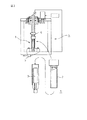
図1に、圧電部品10を製造する工程において用いられる圧入装置11を示す。
この圧入装置11は、圧電部品10を製造する工程において、圧電部品10における圧入部材(後述)を、被圧入部材である圧電素子(後述)に所定量、圧入する工程を行うものである。
すなわち、圧入装置11は、被圧入部材である圧電素子をクランプし保持するワーク保持部12と、圧入部材を被圧入部材に向けて押圧する圧入手段である加圧動作部13と、加圧動作部13における圧入パンチ(後述)のピストンが圧電素子に接触することで発生する接触電圧にかかる出力信号等を受信し、加圧動作部13を操作する制御信号を出力する制御部14とを備えている。
Hereinafter, a preferred embodiment of a press-fitting device for manufacturing a piezoelectric component according to the present invention will be described with reference to the accompanying drawings.
FIG. 1 shows a press-
The press-
That is, the press-
ワーク保持部12はテーブル15上に設置され、加圧動作部13は、フレーム16を介してテーブル15に立設されている。
加圧動作部13は、圧入部材に当接する圧入パンチ17とサーボモータ18と、伝達機構部19を介してサーボモータ18に連結され圧入パンチ17に当接するボールネジ20とを有する。
The
The
なお、ボールネジ20の上端部とテーブル15の面(基準面)との間には、変位センサ21が配設されており、ボールネジ20の移動量をサーボモータ18にフィードバックし、ボールネジ20の移動量を精度良く制御するようにしている。
A
ここで、対象ワークである、圧電部品10の構成について説明する。かかる圧電部品10は、圧電アクチュエータとして製造する工程のうち、圧入工程によって得られる部品を示しており、実質的に、支持基部22により支持される圧電素子23と、圧電素子23を支える支持基部22に圧入してなる収納ケース24である円筒状のパイプ24と、支持基部22に介装している圧電素子端子23aと、圧電素子端子23aの先端部に設けた、ターミナル部22aとによって構成している。
Here, the configuration of the
また、以上のような圧電部品10として形成されるために、圧入装置11における加圧動作部13の圧入パンチ17によって、圧入部材であるパイプ24を、被圧入部材である圧電素子23に向けて押圧して圧入する工程を実行するわけであるが、加圧動作部13の圧入パンチ17は、ボールネジ20先端部に設けられる。
また、かかる圧入パンチ17には、中心軸に同心的に圧入部材であるパイプ24が把持され、中心軸に同心的に、圧入パンチ17に対して独立的に昇降動作するピストン押圧具25を配設している。
そして、ピストン押圧具25には、ピストン26を、ピストン押圧具25の中心軸に対して適宜角度偏向した状態でバネ部材27を介して揺動可能に取付けている。
ピストン26は、圧入パンチ17にパイプ24を把持した際に、パイプ24内において所定の間隔Gを以って、圧電素子23上端面と対向するようにしている。
Further, since the
Further, the press-
Then, the
The
次に、加圧動作部13を操作する制御信号を出力する制御部14について説明する。
制御部14は、前述のように、加圧動作部13における圧入パンチ17のピストン26が圧電素子23に接触することで発生する接触電圧にかかる出力信号等を受信し、加圧動作部13を操作する制御信号を出力する構成であるが、圧入加工時に、圧入装置11におけるワーク保持部12に、圧電素子23を支える支持基部22を保持した際に、支持基部22内の圧電素子端子23aの先端部のターミナル部22aに、電気的に接続される電圧計28の電圧信号を取り込んでいる。
そして、制御部14は、かかる電圧計28によって得られる圧入パンチ17のピストン26が圧電素子23に接触することで発生する接触電圧にかかる出力信号等に基づいて、後述する手順に従って、加圧動作部13のサーボモータ18を作動制御するように構成されている。
Next, the control unit 14 that outputs a control signal for operating the pressurizing
As described above, the control unit 14 receives an output signal or the like relating to the contact voltage generated when the
Then, the control unit 14 performs a pressurizing operation in accordance with a procedure to be described later based on an output signal or the like relating to a contact voltage generated when the
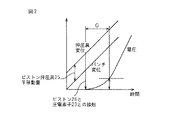
本発明にかかる圧電部品を製造するための圧入装置11は以上のように構成されるものであり、次に、圧入装置11による圧入工程について、図2に示すグラフを参照しながら説明する。
先ず、圧入装置11におけるテーブル15上のワーク保持部12に、被圧入部材である圧電素子23を支える支持基部22を保持する。
次いで、支持基部22内の圧電素子端子23aの先端部のターミナル部22aに、電圧計28を接続する。
ここで、加圧動作部13における圧入パンチ17に、圧入部材である円筒状のパイプ24を把持する。次に、圧入パンチ17中心部に同軸的に設けられたピストン押圧具25を所定量下降させる。これにより、ピストン押圧具25に支持されたピストン26が接触し、圧入パンチ17に把持されるパイプ24との位置関係が相対的に変わることなく維持される。
ピストン26は、ピストン押圧具25にバネ部材27を介して偏向状態に保持されているが、ピストン26は、バネ部材27のバネ力に抗して変位し、圧電素子23上端に密接させることができる。このようにすることで、ピストン26は、圧電素子23上端に追従して、偏在することなく全体的に当接させることができる。また、この場合、バネ部材27の緩衝作用により、略均圧状態で当接することができる。
The press-fitting
First, the
Next, a
Here, the
The
かかる状態で、圧入装置11の制御部14に動作指令を与えて、加圧動作部13のサーボモータ18を駆動させ、ボールネジ20を作動させて、ボールネジ20先端の圧入パンチ17を下降させることで、圧入パンチ17に把持したパイプ24を圧電素子23を支える支持基部22に圧入することができる。
In this state, an operation command is given to the control unit 14 of the press-fitting
圧入パンチ17を下降させていくと、パイプ24が、圧電素子23を支える支持基部22に圧入されていき、ピストン26と圧電素子23との接触圧が増加し、発生する接触電圧が上昇していく。この接触電圧は、圧電素子端子23aの先端部のターミナル部22aに接続した電圧計28によって計測され、電圧計28から接触電圧にかかる出力信号が制御部14に送られる。
従って、制御部14は、パイプ24が所定の位置まで圧入されたことを、接触電圧にかかる出力信号によって把握することができる。なお、パイプ24がどの程度圧入されたかは、電圧計28を用いたことにより、目視によって確認することもできる。
When the press-fitting
Therefore, the control part 14 can grasp | ascertain that the
そして、制御部14は、接触電圧にかかる出力信号によってパイプ24が所定の位置まで圧入されたことを把握したら、加圧動作部13のサーボモータ18を停止させ、今度は、サーボモータ18を逆転駆動して、ボールネジ20を逆転させて、ボールネジ20先端の圧入パンチ17およびピストン押圧具25を上昇させる。
そして、パイプ24が所定位置まで圧入された状態の圧電部品10として取出すことができ、かかる圧電部品10を後続の工程へと送ることができる。
When the control unit 14 grasps that the
And it can take out as the
以上のように、圧電部品を製造するに当たり、圧電素子に部品を高精度に圧入する際、圧電素子自体の起電力を利用することで、圧入装置で用いられるロードセルや位置決めセンサなどのセンサ類を不要とすることができ、設備コストを大幅に抑制することができる。
しかも、前述の圧入方法によって、圧電部品のパイプ内の圧電素子に偏芯が生じることないように、パイプを圧電素子に高精度に圧入することができ、高品質な圧電部品を製造することができる。
As described above, when manufacturing a piezoelectric component, when the component is press-fitted into the piezoelectric element with high accuracy, the electromotive force of the piezoelectric element itself is used to obtain sensors such as a load cell and a positioning sensor used in the press-fitting device. It can be unnecessary, and the equipment cost can be greatly reduced.
In addition, the above-described press-fitting method allows the pipe to be pressed into the piezoelectric element with high accuracy so that the piezoelectric element in the pipe of the piezoelectric component does not become eccentric, thereby producing a high-quality piezoelectric component. it can.
10 圧電部品
11 圧入装置
12 ワーク保持部
13 加圧動作部
14 制御部
15 テーブル
16 フレーム
17 圧入パンチ
18 サーボモータ
19 伝達機構部
20 ボールネジ
21 変位センサ
22 支持基部
22a ターミナル部
23 圧電素子
23a 圧電素子端子
24 パイプ
25 ピストン押圧具
26 ピストン
27 バネ部材
28 電圧計
G 隙間
DESCRIPTION OF
Claims (2)
前記収納ケース(24)を把持すると共に前記圧電素子(23)に圧入するための圧入パンチ(17)と、
前記圧入パンチ(17)に同軸的に配置して、圧入パンチ(17)とは独立して作動可能なピストン押圧具(25)と、
前記ピストン押圧具(25)に、バネ部材(27)を介して変動可能に支持して、前記圧電素子(23)端面に当接し押圧するピストン(26)と、
前記圧入パンチ(17)に押圧力を付与する加圧動作部(13)と、
前記加圧動作部(13)により、前記ピストン押圧具(25)を予め作動させて前記圧電素子(23)端面に前記ピストン(26)を当接した状態で、前記圧入パンチ(17)を作動させて前記収納ケース(24)を前記圧電素子(23)に圧入し、前記ピストン(26)と圧電素子(23)との接触によって生じる電圧を監視して、このピストン−圧電素子接触電圧が所定電圧に達した時点で、前記加圧動作部(13)を停止させ、前記加圧動作部(13)を逆転駆動して、前記圧入パンチ(17)およびピストン押圧具(25)を退動させる制御部(14)と、
を具備していて、
前記ピストン(26)は、前記ピストン押圧具(25)に、ピストン押圧具(25)の中心軸に対して適宜角度偏向した状態でバネ部材(27)を介して揺動可能に取付けていることを特徴とする圧電部品を製造するための圧入装置。 A work holding portion (12) for holding a piezoelectric element (23) as a press-fit member for press-fitting a storage case (24) as a press-fit member;
A press-fitting punch (17) for gripping the storage case (24) and press-fitting into the piezoelectric element (23);
A piston pressing tool (25) disposed coaxially with the press-fitting punch (17) and operable independently of the press-fitting punch (17);
A piston (26) that is variably supported on the piston pressing tool (25) via a spring member (27), and abuts against and presses the end face of the piezoelectric element (23);
A pressurizing operation unit (13) for applying a pressing force to the press-fitting punch (17);
The press-fitting punch (17) is actuated in a state in which the piston pressing tool (25) is actuated in advance and the piston (26) is in contact with the end face of the piezoelectric element (23) by the pressurizing operation part (13). Then, the storage case (24) is press-fitted into the piezoelectric element (23), and the voltage generated by the contact between the piston (26) and the piezoelectric element (23) is monitored. When the voltage is reached, the pressurizing unit (13) is stopped, the pressurizing unit (13) is driven in reverse, and the press-fitting punch (17) and the piston pressing tool (25) are moved backward. A control unit (14);
If it is provided with a,
The piston (26) is swingably attached to the piston pressing tool (25) via a spring member (27) in a state where the piston (26) is appropriately deflected with respect to the central axis of the piston pressing tool (25). A press-fitting device for manufacturing a piezoelectric component characterized by the above.
Priority Applications (1)
| Application Number | Priority Date | Filing Date | Title |
|---|---|---|---|
| JP2008135907A JP4840407B2 (en) | 2008-05-23 | 2008-05-23 | Press-fitting device for manufacturing piezoelectric parts |
Applications Claiming Priority (1)
| Application Number | Priority Date | Filing Date | Title |
|---|---|---|---|
| JP2008135907A JP4840407B2 (en) | 2008-05-23 | 2008-05-23 | Press-fitting device for manufacturing piezoelectric parts |
Publications (2)
| Publication Number | Publication Date |
|---|---|
| JP2009279723A JP2009279723A (en) | 2009-12-03 |
| JP4840407B2 true JP4840407B2 (en) | 2011-12-21 |
Family
ID=41450726
Family Applications (1)
| Application Number | Title | Priority Date | Filing Date |
|---|---|---|---|
| JP2008135907A Expired - Fee Related JP4840407B2 (en) | 2008-05-23 | 2008-05-23 | Press-fitting device for manufacturing piezoelectric parts |
Country Status (1)
| Country | Link |
|---|---|
| JP (1) | JP4840407B2 (en) |
Families Citing this family (2)
| Publication number | Priority date | Publication date | Assignee | Title |
|---|---|---|---|---|
| RU181819U1 (en) * | 2017-08-14 | 2018-07-26 | федеральное государственное бюджетное образовательное учреждение высшего образования "Ижевский государственный технический университет имени М.Т. Калашникова" | MECHATRONIC PIEZOMODULE FOR ASSEMBLY WITH PRESSING CERAMIC PARTS |
| RU2732020C2 (en) * | 2018-06-06 | 2020-09-10 | федеральное государственное бюджетное образовательное учреждение высшего образования "Ижевский государственный технический университет имени М.Т. Калашникова" | High-precision conical ceramic connections with interference fit method |
Family Cites Families (5)
| Publication number | Priority date | Publication date | Assignee | Title |
|---|---|---|---|---|
| JP3511799B2 (en) * | 1996-04-15 | 2004-03-29 | 株式会社デンソー | Method and apparatus for manufacturing press-fit connecting member |
| JP4244085B2 (en) * | 1999-03-17 | 2009-03-25 | 株式会社デンソー | Press-fitting device and press-fitting method |
| JP2004142028A (en) * | 2002-10-24 | 2004-05-20 | Toyota Motor Corp | Press-in method and press-in device |
| JP2005335017A (en) * | 2004-05-27 | 2005-12-08 | Kyoho Mach Works Ltd | Press-fitting device |
| JP2008041983A (en) * | 2006-08-08 | 2008-02-21 | Denso Corp | Piezoelectric actuator |
-
2008
- 2008-05-23 JP JP2008135907A patent/JP4840407B2/en not_active Expired - Fee Related
Also Published As
| Publication number | Publication date |
|---|---|
| JP2009279723A (en) | 2009-12-03 |
Similar Documents
| Publication | Publication Date | Title |
|---|---|---|
| CN103042295B (en) | Pressure control method of spot welding device | |
| CN103228389B (en) | There is the soldering tip of force snesor, spring and adjustment element | |
| US9108265B2 (en) | Spot welding apparatus | |
| JP5926439B1 (en) | Ultrasonic bonding equipment | |
| CN102689088A (en) | Spot welding apparatus and spot welding method | |
| JP4943917B2 (en) | Welding apparatus and welding method | |
| JP4840407B2 (en) | Press-fitting device for manufacturing piezoelectric parts | |
| US9040866B2 (en) | Spot welding apparatus | |
| JP5380906B2 (en) | Caulking device and caulking method | |
| JP2009000731A (en) | Lid tacking device | |
| JP2022015562A (en) | Friction stir point joining device and friction stir point joining method | |
| JP5860281B2 (en) | Spot welding equipment | |
| JP5813466B2 (en) | Spot welding equipment | |
| JP2013071172A (en) | Spot welding equipment | |
| JP2002035951A (en) | Method and apparatus for detecting position of member to be welded | |
| JP2010005891A (en) | Heat-caulking device and method | |
| JPH11291060A (en) | Resistance welding method and its device | |
| WO2000010767A1 (en) | Resistance welding device | |
| JP5969747B2 (en) | Spot welding equipment | |
| JP2002219579A (en) | Method and apparatus for controlling welding robot | |
| JP2009160612A (en) | Spot welding apparatus | |
| JPH10180562A (en) | Tight fitting method and tight fitting device | |
| JP7255119B2 (en) | Indirect spot welding device and welding method | |
| JP2014018861A (en) | Welding equipment and welding method of projection nut | |
| JPH09295158A (en) | Spot welding gun |
Legal Events
| Date | Code | Title | Description |
|---|---|---|---|
| A621 | Written request for application examination |
Free format text: JAPANESE INTERMEDIATE CODE: A621 Effective date: 20100607 |
|
| A977 | Report on retrieval |
Free format text: JAPANESE INTERMEDIATE CODE: A971007 Effective date: 20110218 |
|
| A131 | Notification of reasons for refusal |
Free format text: JAPANESE INTERMEDIATE CODE: A131 Effective date: 20110222 |
|
| A521 | Written amendment |
Free format text: JAPANESE INTERMEDIATE CODE: A523 Effective date: 20110407 |
|
| TRDD | Decision of grant or rejection written | ||
| A01 | Written decision to grant a patent or to grant a registration (utility model) |
Free format text: JAPANESE INTERMEDIATE CODE: A01 Effective date: 20110906 |
|
| A01 | Written decision to grant a patent or to grant a registration (utility model) |
Free format text: JAPANESE INTERMEDIATE CODE: A01 |
|
| A61 | First payment of annual fees (during grant procedure) |
Free format text: JAPANESE INTERMEDIATE CODE: A61 Effective date: 20110919 |
|
| R151 | Written notification of patent or utility model registration |
Ref document number: 4840407 Country of ref document: JP Free format text: JAPANESE INTERMEDIATE CODE: R151 |
|
| FPAY | Renewal fee payment (event date is renewal date of database) |
Free format text: PAYMENT UNTIL: 20141014 Year of fee payment: 3 |
|
| R250 | Receipt of annual fees |
Free format text: JAPANESE INTERMEDIATE CODE: R250 |
|
| R250 | Receipt of annual fees |
Free format text: JAPANESE INTERMEDIATE CODE: R250 |
|
| R250 | Receipt of annual fees |
Free format text: JAPANESE INTERMEDIATE CODE: R250 |
|
| R250 | Receipt of annual fees |
Free format text: JAPANESE INTERMEDIATE CODE: R250 |
|
| R250 | Receipt of annual fees |
Free format text: JAPANESE INTERMEDIATE CODE: R250 |
|
| R250 | Receipt of annual fees |
Free format text: JAPANESE INTERMEDIATE CODE: R250 |
|
| LAPS | Cancellation because of no payment of annual fees |