JP4835986B2 - Electric steering control device - Google Patents
Electric steering control device Download PDFInfo
- Publication number
- JP4835986B2 JP4835986B2 JP2006165663A JP2006165663A JP4835986B2 JP 4835986 B2 JP4835986 B2 JP 4835986B2 JP 2006165663 A JP2006165663 A JP 2006165663A JP 2006165663 A JP2006165663 A JP 2006165663A JP 4835986 B2 JP4835986 B2 JP 4835986B2
- Authority
- JP
- Japan
- Prior art keywords
- torque
- steering
- acceleration operation
- vehicle
- torque steer
- Prior art date
- Legal status (The legal status is an assumption and is not a legal conclusion. Google has not performed a legal analysis and makes no representation as to the accuracy of the status listed.)
- Expired - Fee Related
Links
Images


Classifications
-
- B—PERFORMING OPERATIONS; TRANSPORTING
- B62—LAND VEHICLES FOR TRAVELLING OTHERWISE THAN ON RAILS
- B62D—MOTOR VEHICLES; TRAILERS
- B62D5/00—Power-assisted or power-driven steering
- B62D5/04—Power-assisted or power-driven steering electrical, e.g. using an electric servo-motor connected to, or forming part of, the steering gear
- B62D5/0457—Power-assisted or power-driven steering electrical, e.g. using an electric servo-motor connected to, or forming part of, the steering gear characterised by control features of the drive means as such
- B62D5/046—Controlling the motor
- B62D5/0472—Controlling the motor for damping vibrations
Landscapes
- Engineering & Computer Science (AREA)
- Chemical & Material Sciences (AREA)
- Combustion & Propulsion (AREA)
- Transportation (AREA)
- Mechanical Engineering (AREA)
- Steering Control In Accordance With Driving Conditions (AREA)
- Power Steering Mechanism (AREA)
- Arrangement And Driving Of Transmission Devices (AREA)
Description
本発明は、車両の電動ステアリング制御装置に関し、特に、ドライブシャフトの配置及び特性に起因する定常的及び過渡的なトルクステアを低減する電動ステアリング制御装置に係る。 The present invention relates to an electric steering control device for a vehicle, and more particularly to an electric steering control device that reduces steady and transient torque steer caused by the arrangement and characteristics of a drive shaft.
一般的に、操向車輪が駆動車輪である車両のステアリング装置において、駆動力の変化に応じて操舵力や保舵力が変化する現象がトルクステアと呼ばれており、このトルクステアを抑制することが望まれている。例えば後掲の特許文献1には、駆動力(又は制動力)を左右輪それぞれ独立して(又は左右輪に対して配分して)制御して車両の操縦性及び安定性を向上させるようにした左右輪制御システムを搭載した車両が開示されている。具体的には、上記の制御により左右不均等な駆動力(又は制動力)が操向輪(転舵輪)に作用した場合に、操向輪側からハンドルを回してしまうトルクステアを抑制することを目的として、駆動力又は制動力を左右輪に対してそれぞれ独立して制御し得る左右輪制御による駆動力又は制動力における左右輪間の制御値に差が生じたときに、該制御値の差により発生するトルクステアを打ち消す向きに操向輪を転舵させるためのトルクステア防止補助トルク信号を出力し、電動機を制御する電動パワーステアリング装置が提案されている。 In general, in a steering apparatus for a vehicle in which the steering wheel is a drive wheel, a phenomenon in which the steering force or the holding force changes in accordance with a change in the driving force is called torque steer, and this torque steer is suppressed. It is hoped that. For example, in Patent Document 1 described later, the driving force (or braking force) is controlled independently for each of the left and right wheels (or distributed to the left and right wheels) to improve the maneuverability and stability of the vehicle. A vehicle equipped with the left and right wheel control system is disclosed. Specifically, the torque steer that turns the steering wheel from the steered wheel side when the left and right uneven driving force (or braking force) acts on the steered wheel (steered wheel) by the above control is suppressed. For the purpose of the above, when a difference occurs in the control value between the left and right wheels in the driving force or the braking force by the left and right wheel control capable of controlling the driving force or the braking force independently for the left and right wheels, the control value There has been proposed an electric power steering device that outputs a torque steer prevention auxiliary torque signal for turning a steered wheel in a direction to cancel torque steer generated by the difference, and controls the electric motor.
更に、後掲の特許文献2において、上記特許文献1では左右輪の間の制御値に差が発生した場合のみ、つまり左右輪に回転差が発生した場合のみにトルクステアの抑制制御を行っているが、摩擦抵抗の大きい路面上では、左右輪間に回転差が生じていない状態、あるいは微小な回転差が発生している場合でも、トルクステアが発生しているとして、これを解決する装置が提案されている。即ち、左右駆動輪の回転差ではなく、トルクステアが発生するおそれのある左右の駆動軸の伝達トルク差をみて、トルクステアを打ち消すために、エンジントルクを検出または推定し、エンジントルクに対する左右の駆動軸にかかるトルク差の関係を記憶した記憶回路によって、トルクステア推定値を求め、左右の駆動軸の伝達トルク差によって発生するトルクステアを打ち消す操舵制御装置が提案されている。尚、操向車輪が駆動車輪である車両に関連し、下記の特許文献3に記載のように、四輪駆動式自動車等における左右輪への駆動力配分を行う駆動力配分装置も提案されている。 Further, in Patent Document 2 described later, in Patent Document 1, torque steer suppression control is performed only when a difference occurs in the control value between the left and right wheels, that is, only when a rotation difference occurs between the left and right wheels. However, on a road surface with high frictional resistance, even if there is no rotational difference between the left and right wheels, or even when a small rotational difference has occurred, a device that solves this is considered to be torque steer. Has been proposed. That is, the engine torque is detected or estimated in order to cancel the torque steer by looking at the transmission torque difference between the left and right drive shafts where torque steer may occur rather than the rotation difference between the left and right drive wheels. There has been proposed a steering control device that obtains an estimated torque steer value by a storage circuit that stores a relationship between torque differences applied to the drive shafts, and cancels torque steer generated due to a difference in transmission torque between the left and right drive shafts. A driving force distribution device that distributes the driving force to the left and right wheels in a four-wheel drive vehicle or the like has been proposed as described in Patent Document 3 below in relation to a vehicle whose steering wheel is a driving wheel. Yes.
然し乍ら、前掲の特許文献2のように、エンジントルクに対する左右の駆動軸トルク差の関係によるトルクステアの補償では、依然として、後述する過渡的なトルクステアを充分に低減することが困難となる。 However, as in Patent Document 2 described above, it is still difficult to sufficiently reduce the transient torque steer described later in the torque steer compensation based on the relationship between the left and right drive shaft torque differences with respect to the engine torque.
ここで、トルクステアが発生する原因について解析する。トルクステアとは、操向車輪が駆動車輪となる車両(フロントエンジン・フロントドライブ車(所謂FF車)又は四輪駆動車)において、車両の加速時に、操向車輪側からステアリングホイールが転舵される現象(操向車輪がステアリングホイールを転舵する現象)をいう。このトルクステアの発生原因には、主として、「ドライブシャフトの等速ジョイントの折れ角」、及び「キングピンオフセットが存在する場合の左右車輪間での駆動力の差」が挙げられる。 Here, the cause of torque steer is analyzed. Torque steer means that in a vehicle (front engine / front drive vehicle (so-called FF vehicle) or four-wheel drive vehicle) whose steering wheel is a driving wheel, the steering wheel is steered from the steering wheel side when the vehicle is accelerated. (Steering wheel steers the steering wheel). The causes of the torque steer are mainly “the bending angle of the constant velocity joint of the drive shaft” and “the difference in driving force between the left and right wheels when a kingpin offset is present”.
先ず、(1)として「ドライブシャフトの等速ジョイントの折れ角によるトルクステア」について説明する。ドライブシャフトと車輪の関係を 図17に示すように、ドライブシャフトの等速ジョイントが折れ角θを持つ場合、ドライブシャフトが伝達する駆動トルクをTdrvとすると、下記(1)式に基づき、車輪を転舵しようとする2次偶力モーメントMzが発生する。
Mz=Tdrv・tan(θ/2) ---(1)
First, as (1), “torque steer by the bending angle of the constant velocity joint of the drive shaft” will be described. As shown in FIG. 17, when the constant velocity joint of the drive shaft has a bending angle θ, the drive torque transmitted by the drive shaft is Tdrv, as shown in FIG. A secondary couple moment Mz to be steered is generated.
Mz = Tdrv · tan (θ / 2) --- (1)
図18には、操向車輪が駆動車輪である車両におけるステアリング装置を含む部分に関し、正面及び平面の対応関係が明らかとなるように示されている。即ち、図18において、エンジンコンパートメントの空間効率を確保するために、エンジンEG及び変速機TRが、車両進行方向に対して横置きの配置とされている車両では、ドライブシャフト(駆動軸ともいう)DS1及びDS2の長さや取付け配置は、左右対称とはならない。そのため、駆動車輪に接続されるドライブシャフトのジョイント折れ角が左右の車輪WH1,WH2間で異なっている場合には、車輪を転舵するモーメント(転舵トルクともいう)Mzが、左右の車輪WH1,WH2間で差が生じ、車両の加速時に操向車輪がステアリングホイールSWを転舵するトルクステアが発生する。このように、ドライブシャフトの等速ジョイントの折れ角に起因するトルクステアを、定常的なトルクステアという。 FIG. 18 shows the correspondence between the front and the plane with respect to the portion including the steering device in the vehicle in which the steered wheels are drive wheels. That is, in FIG. 18, in order to ensure the space efficiency of the engine compartment, in a vehicle in which the engine EG and the transmission TR are arranged horizontally with respect to the vehicle traveling direction, a drive shaft (also referred to as a drive shaft). The length and mounting arrangement of DS1 and DS2 are not symmetrical. Therefore, when the joint bend angle of the drive shaft connected to the drive wheel is different between the left and right wheels WH1, WH2, the moment (also referred to as turning torque) Mz for turning the wheel is equal to the left and right wheels WH1. , WH2, and a torque steer occurs in which the steered wheels steer the steering wheel SW during acceleration of the vehicle. Thus, the torque steer resulting from the bending angle of the constant velocity joint of the drive shaft is called steady torque steer.
次に、(2)として「キングピンオフセットが存在する場合の左右車輪間での駆動力の差によるトルクステア」について説明する。図18に示すように、操向車輪(WH1,WH2)は転舵可能となるようにキングピンKP1,KP2を有しており、転舵の中心点TC(キングピン軸と路面との交点)の位置と駆動力の着力点DPの位置は一致せず、その2点間の距離であるキングピンオフセットKPoが存在する(図18のKPcはホイールセンタ・キングピンオフセットを表す)。キングピンオフセットKPoが存在する場合は、車輪WH1,WH2に駆動力が作用する車両加速時には、車輪を転舵するトルク(転舵トルク)が発生するが、これは(駆動力)×(キングピンオフセット)として求められる。左右の車輪WH1,WH2間で駆動力が一致しておれば、この転舵トルクは相殺されてトルクステアは発生しないが、左右の車輪WH1,WH2の駆動力が相違する場合には、「操向車輪(左右車輪)がステアリングホイールを転舵するトルクステア」が発生する。 Next, as (2), “torque steer due to difference in driving force between right and left wheels when a kingpin offset exists” will be described. As shown in FIG. 18, the steered wheels (WH1, WH2) have kingpins KP1, KP2 so that they can be steered, and the position of the turning center point TC (intersection of the kingpin axis and the road surface). The position of the force application point DP of the driving force does not match, and there is a kingpin offset KPo that is the distance between the two points (KPc in FIG. 18 represents the wheel center kingpin offset). When the kingpin offset KPo exists, during the acceleration of the vehicle in which the driving force acts on the wheels WH1 and WH2, torque (steering torque) for turning the wheel is generated, which is (driving force) × (kingpin offset). As required. If the driving force is the same between the left and right wheels WH1, WH2, this steering torque is offset and torque steer does not occur. However, if the driving forces of the left and right wheels WH1, WH2 are different, "Torque steer where the right wheels (left and right wheels) steer the steering wheel" occurs.
更に、上記(2)のように左右車輪間で駆動力が異なる場合としては、以下の三つの場合が考えられる。
(2−a)「ドライブシャフトの特性による駆動力左右差」
ドライブシャフトDS1及びDS2に特性差がある場合には、トルク伝達に過渡的な(動的な)差異が生じる。ドライブシャフトDS1及びDS2が、同一材質、同一断面形状であっても、それらの長さが異なると、ドライブシャフトのねじり剛性は異なる。車両が急加速する場合、ドライブシャフト長が短くねじり剛性が高い側の車輪では駆動力が僅かな遅れで、速やかに立ち上がる。これに対し、ドライブシャフト長が長くねじり剛性が低い側の車輪では駆動力の立ち上がりは緩やかとなる。そのため、過渡的な駆動力に左右差が生じ、これによるトルクステア(過渡的なトルクステアという)が発生する。
Furthermore, the following three cases can be considered as the case where the driving force differs between the left and right wheels as in (2) above.
(2-a) "Driving force difference due to drive shaft characteristics"
When there is a characteristic difference between the drive shafts DS1 and DS2, a transient (dynamic) difference occurs in torque transmission. Even if the drive shafts DS1 and DS2 have the same material and the same cross-sectional shape, the torsional rigidity of the drive shaft differs if their lengths are different. When the vehicle accelerates rapidly, the driving force of the wheel having a short drive shaft length and high torsional rigidity rises quickly with a slight delay. On the other hand, the driving force rises gently at the wheel having a long drive shaft length and low torsional rigidity. Therefore, there is a left-right difference in the transient driving force, and torque steer (referred to as transient torque steer) due to this occurs.
(2−b)「トラクション制御による駆動力左右差」
トラクション制御によって、一方の車輪に制動トルクが加えられると、その制動トルクに相当する他方の車輪の駆動力が増加する。特に、路面摩擦係数が左右車輪間で異なる、所謂μスプリット路面において、トラクション制御が作動した場合には、駆動力の左右差が大きく発生する。
(2-b) “Driving force left / right difference by traction control”
When braking torque is applied to one wheel by traction control, the driving force of the other wheel corresponding to the braking torque increases. In particular, when the traction control is activated on a so-called μ-split road surface where the road surface friction coefficient is different between the left and right wheels, a large left-right difference in driving force is generated.
(2−c)「駆動力配分装置による駆動力左右差」
左右車輪間に駆動力配分装置を備える場合にも、駆動力の左右差が発生する。尚、駆動力配分装置には、電子制御によるものと、機械的に差動を制限するもの(例えば、ビスカスカップリング等)があり、例えば前掲の特許文献3に開示されている。
(2-c) “Driving force left / right difference by driving force distribution device”
Even when a driving force distribution device is provided between the left and right wheels, a left-right difference in driving force occurs. There are two types of driving force distribution devices, one based on electronic control and the other that mechanically limits differentials (for example, viscous coupling), which are disclosed in, for example, the above-mentioned Patent Document 3.
そこで、本発明は、電動ステアリング制御装置において、簡便な装置によって効果的にトルクステアを低減することを課題とし、特に、加速操作が所定値以上となったときに、ドライブシャフトの特性、例えばドライブシャフトのねじり剛性差による駆動力左右差に起因する過渡的なトルクステアを効果的に低減することを目的とする。 Accordingly, an object of the present invention is to effectively reduce torque steer by a simple device in an electric steering control device, and particularly when an acceleration operation becomes a predetermined value or more, characteristics of a drive shaft, for example, a drive The object is to effectively reduce the transient torque steer caused by the difference in driving force due to the difference in torsional rigidity of the shaft.
上記の課題を達成するため、本発明は、請求項1に記載のように、動力源が発生する動力を、ドライブシャフトを介して駆動車輪に伝達する車両における操向車輪が前記駆動車輪である当該車両に搭載し、当該車両のステアリングホイールの操舵トルクを制御する操舵トルク制御手段を備えた電動ステアリング制御装置において、運転者の加速操作を検出する加速操作検出手段を備え、前記操舵トルク制御手段は、前記加速操作検出手段が検出する加速操作量が所定値以上となったときに、前記ドライブシャフトの特性に起因して前記ステアリングホイールに過渡的に発生するトルクステアを低減させるトルクステア低減トルクを、パルス波形として決定し、該パルス波形のトルクステア低減トルクを前記ステアリングホイールに付与することとしたものである。 To achieve the above object, according to the present invention, the steering wheel in the vehicle that transmits the power generated by the power source to the driving wheel via the drive shaft is the driving wheel. An electric steering control device equipped with a steering torque control means for controlling a steering torque of a steering wheel of the vehicle mounted on the vehicle, comprising an acceleration operation detection means for detecting an acceleration operation of a driver, the steering torque control means Is a torque steer reduction torque that reduces torque steer that transiently occurs in the steering wheel due to the characteristics of the drive shaft when the acceleration operation amount detected by the acceleration operation detection means exceeds a predetermined value. and determined as a pulse waveform, imparting child torque steer reducing torque of the pulse waveform to the steering wheel It is obtained by the.
あるいは、請求項2に記載のように、動力源が発生する動力を、ドライブシャフトを介して駆動車輪に伝達する車両における操向車輪が前記駆動車輪である当該車両に搭載し、当該車両のステアリングホイールの操舵トルクを制御する操舵トルク制御手段を備えた電動ステアリング制御装置において、運転者の加速操作を検出する加速操作検出手段を備え、前記操舵トルク制御手段は、前記車両の発進時に、前記加速操作検出手段が検出する加速操作量が所定値以上となったときに、前記ドライブシャフトの特性に起因して前記ステアリングホイールに過渡的に発生するトルクステアを低減させるトルクステア低減トルクを、パルス波形として決定し、該パルス波形のトルクステア低減トルクを前記ステアリングホイールに付与するように構成してもよい。 Alternatively, as described in claim 2, the steering wheel in the vehicle that transmits the power generated by the power source to the driving wheel via the drive shaft is mounted on the vehicle, and the steering of the vehicle. An electric steering control device having a steering torque control means for controlling a steering torque of a wheel, further comprising an acceleration operation detection means for detecting a driver's acceleration operation, wherein the steering torque control means is configured to accelerate the vehicle when the vehicle starts. When the acceleration operation amount detected by the operation detecting means exceeds a predetermined value, a torque steer reducing torque for reducing torque steer transiently generated in the steering wheel due to the characteristics of the drive shaft is generated in a pulse waveform. determined as, configured to impart torque steer reducing torque of the pulse waveform to the steering wheel It may be.
上記電動ステアリング制御装置において、前記操舵トルク制御手段は、請求項3に記載のように、前記加速操作量の時間変化を演算する加速操作速度演算手段を備えたものとし、前記操舵トルク制御手段が、前記パルス波形の形状を前記加速操作量、及び前記加速操作速度演算手段が演算する加速操作速度のうちの少なくとも一方に応じて決定するように構成してもよい。 In the electric steering controller, the steering torque control means as claimed in claim 3, and those with acceleration operation speed calculating means for calculating a time change of the acceleration operation quantity, the steering torque control means The shape of the pulse waveform may be determined according to at least one of the acceleration operation amount and the acceleration operation speed calculated by the acceleration operation speed calculation means.
更に、請求項4に記載のように、前記車両が前記動力源と前記ドライブシャフトの間に介装する変速機を備えたものであれば、前記操舵トルク制御手段は、前記変速機の減速比が所定値より小さいときには、前記トルクステア低減トルクの付与を禁止するように構成とするとよい。また、請求項5に記載のように、前記車両の速度を検出する車両速度検出手段を備えたものであれば、前記操舵トルク制御手段は、前記車両速度検出手段の検出する車両速度が所定値より大きいときには前記トルクステア低減トルクの付与を禁止するように構成してもよい。 Further, as described in claim 4, as long as the vehicle is equipped with a transmission that is interposed between said drive shaft and said power source, said steering torque control means, the reduction ratio of the transmission When is smaller than a predetermined value, the application of the torque steer reducing torque may be prohibited. Further, as described in claim 5 , if the vehicle speed detecting means for detecting the speed of the vehicle is provided, the steering torque control means is configured such that the vehicle speed detected by the vehicle speed detecting means is a predetermined value. When it is larger, the application of the torque steer reducing torque may be prohibited.
そして、請求項6に記載のように、前記操舵トルク制御手段を、前記トルクステア低減トルクの付与を、前記ステアリングホイールの右旋回方向及び左旋回方向のうちで、前記ドライブシャフトの特性によって予め定まる何れか一方向に限定して行うように構成してもよい。 According to a sixth aspect of the present invention, the steering torque control means applies the torque steer reducing torque in advance according to the characteristics of the drive shaft in the right turning direction and the left turning direction of the steering wheel. You may comprise so that it may restrict | limit to any one fixed direction.
本発明は上述のように構成されているので以下の効果を奏する。即ち、請求項1に記載の電動ステアリング制御装置においては、加速操作量が所定値以上となったときに、ドライブシャフトの特性に起因してステアリングホイールに過渡的に発生するトルクステアを低減させるトルクステア低減トルクを、パルス波形として決定し、このパルス波形のトルクステア低減トルクをステアリングホイールに付与するように構成されているので、トルクステア低減トルクを容易に決定することができ、簡便な装置によって、ドライブシャフトの特性に起因する過渡的なトルクステアを効果的に低減することができ、車両の加速時において運転者の操舵違和感を低減することができる。 Since this invention is comprised as mentioned above, there exist the following effects. That is, in the electric steering control device according to claim 1, when the acceleration operation amount exceeds a predetermined value, the torque for reducing torque steer transiently generated in the steering wheel due to the characteristics of the drive shaft. Since the steering reduction torque is determined as a pulse waveform, and the torque steering reduction torque of this pulse waveform is applied to the steering wheel, the torque steering reduction torque can be easily determined by a simple device. In addition, it is possible to effectively reduce the transient torque steer caused by the characteristics of the drive shaft, and to reduce the driver's uncomfortable feeling during steering of the vehicle.
特に、過渡的なトルクステアは、主として車両の発進加速時に発生することから、請求項2に記載の電動ステアリング制御装置によれば、車両の発進加速時にトルクステア低減制御が実行されるので、ドライブシャフトの特性に起因する過渡的なトルクステアを、効果的に低減することができる。 In particular, since transient torque steer occurs mainly at the time of start acceleration of the vehicle, according to the electric steering control device according to claim 2, torque steer reduction control is executed at the time of vehicle start acceleration. Transient torque steer due to the characteristics of the shaft can be effectively reduced.
例えば、請求項3に記載のように構成すれば、過渡的なトルクステアを一層容易且つ適切に低減することができる。 For example, if it comprises as described in Claim 3 , a transient torque steer can be reduced more easily and appropriately.
更に、請求項4乃至6に記載のように構成すれば、不必要なトルクステア低減トルクの付与を抑制することができ、運転者に対し違和感を与えることなく、過渡的なトルクステアを適切に低減することができる。 Furthermore, if it comprises as described in Claim 4 thru | or 6 , the provision of an unnecessary torque steer reduction torque can be suppressed, and a transient torque steer is appropriately performed without giving a driver a sense of incongruity. Can be reduced.
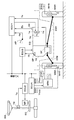
以下、本発明の実施形態について図面を参照して説明する。図1は本発明の一実施形態に係る電動ステアリング制御装置の構成を示すもので、例えば図2に示す車両に搭載される。即ち、動力源としてエンジンEGが発生する動力を、変速機TR及びドライブシャフトDSfl及びDSfrを介して駆動車輪たる車輪WHfr及びWHflに伝達する車両に搭載されるもので、車輪WHfr及びWHflは、ステアリングホイールSWの操作によって転舵される操向車輪でもある。この電動ステアリング制御装置は操舵トルク制御手段を備えており、図1に示す操舵トルク検出手段M1によってステアリングホイールSWの操舵トルクTsが検出され、その検出結果に基づき、パワーステアリング補助トルク目標値決定手段M2において、運転者の操舵力を軽減するためにパワーステアリング制御に補助トルクとして供されるトルクの目標値が演算され、補助トルク目標値Tpsとして出力される。 Embodiments of the present invention will be described below with reference to the drawings. FIG. 1 shows the configuration of an electric steering control device according to an embodiment of the present invention, which is mounted on, for example, the vehicle shown in FIG. That is, it is mounted on a vehicle that transmits the power generated by the engine EG as a power source to the wheels WHfr and WHfl as drive wheels via the transmission TR and the drive shafts DSfl and DSfr. The wheels WHfr and WHfl are It is also a steered wheel steered by the operation of the wheel SW. This electric steering control device includes a steering torque control means, and a steering torque Ts of the steering wheel SW is detected by a steering torque detection means M1 shown in FIG. 1, and based on the detection result, a power steering auxiliary torque target value determination means. In M2, a target value of torque used as auxiliary torque for power steering control in order to reduce the driver's steering force is calculated and output as an auxiliary torque target value Tps.
一方、加速操作検出手段M3によって、運転者の加速操作が検出され、加速操作量Apが出力される。この加速操作量Apは、運転者の操作から駆動力を発生する動力源への入力までにおいて、何れかの個所で検出することができる。例えば、運転者の操作を直接検出するのであれば、アクセルペダルの操作量が加速操作量Apとなる。また、動力源への入力を検出するのであれば、ガソリンエンジンではスルットル開度、ディーゼルエンジンでは燃料噴射量、電気モータでは駆動電流・電圧が加速操作量Apとなる。従って、これらの情報源の間に存在するのであれば、これら以外の情報を検出するものであっても、加速操作検出手段とすることができる。而して、加速操作検出手段M3の検出結果に基づき、判定手段M4において、トルクステア低減トルクを付与するか否かが判定される。 On the other hand, the acceleration operation detecting means M3 detects the driver's acceleration operation and outputs the acceleration operation amount Ap. The acceleration operation amount Ap can be detected at any point from the driver's operation to the input to the power source that generates the driving force. For example, if the operation of the driver is directly detected, the operation amount of the accelerator pedal is the acceleration operation amount Ap. If the input to the power source is to be detected, the throttle opening is a gasoline engine, the fuel injection amount is a diesel engine, and the drive current / voltage is an acceleration operation amount Ap for an electric motor. Therefore, as long as it exists between these information sources, even if it detects information other than these, it can be set as an acceleration operation detection means. Thus, based on the detection result of the acceleration operation detection means M3, the determination means M4 determines whether or not to apply the torque steer reduction torque.
判定手段M4においては、加速操作量Apが所定値Ap1以上となったときに、トルクステア低減トルクの付与が許可される。あるいは、加速操作量Apに基づいて加速操作速度dApを演算し、加速操作量Apが所定値Ap1以上、且つ加速操作速度dApが所定値dAp1以上であるときに、トルクステア低減制御を許可するように判定することとしてもよい。これは、大きな加速操作量であっても緩やかな加速操作変化であれば、ドライブシャフトの過渡的な駆動力差は発生せず、従って、過渡的なトルクステアは生じないためである。 In the determination means M4, when the acceleration operation amount Ap becomes equal to or greater than the predetermined value Ap1, the application of torque steer reduction torque is permitted. Alternatively, the acceleration operation speed dAp is calculated based on the acceleration operation amount Ap, and the torque steer reduction control is permitted when the acceleration operation amount Ap is equal to or greater than the predetermined value Ap1 and the acceleration operation speed dAp is equal to or greater than the predetermined value dAp1. It is good also as determining to. This is because even if the amount of acceleration operation is large, if the acceleration operation changes gradually, no transient driving force difference of the drive shaft occurs, and therefore no transient torque steer occurs.
そして、トルクステア低減トルク目標値決定手段M5において、トルクステア低減トルク目標値Ttsが決定される。このトルクステア低減トルク目標値Ttsは、後述するようにパルス波形として決定される。このパルス波形は、予め設定される固定形状とすることができる。更に、パルス波形は、加速操作量Ap及び加速操作速度dApのうち、少なくとも何れか一方に基づいて可変形状とすることもできる。而して、上記のパワーステアリング制御に供する補助トルク目標値Tpsにトルクステア低減トルク目標値Ttsが加算され、モータ駆動制御手段M6によって、電気モータMTが制御される。 Then, the torque steer reduction torque target value determining means M5 determines the torque steer reduction torque target value Tts. This torque steer reduction torque target value Tts is determined as a pulse waveform as will be described later. This pulse waveform can have a fixed shape set in advance. Further, the pulse waveform may be variable based on at least one of the acceleration operation amount Ap and the acceleration operation speed dAp. Thus, the torque steer reduction torque target value Tts is added to the auxiliary torque target value Tps used for the power steering control, and the electric motor MT is controlled by the motor drive control means M6.
更に、図1に一点鎖線で示すように、変速機状態検出手段M7を設け、図2の変速機TRの変速比Rtを、判定手段M4における判定処理に供することとしてもよい。動力源(エンジンEG)が発生する動力は、変速機TRの減速比(変速比×最終減速比)によって増幅されるため、変速機TRの変速比Rtが小さい場合には、ドライブシャフトに伝達される駆動トルクは、トルクステアを発生させるほどには大きくはならない。そこで、変速機TRの変速比Rtが所定値Rt1より小さい場合には、加速操作量Apが所定値Ap1以上となったときでも、トルクステア低減トルクの付与を禁止し、不必要な操舵トルクの変化を抑制するとよい。また、車両速度が高くなると、変速機TRはシフトアップし、変速比が低くなるため、図1に破線で示すように、車両速度検出手段M8を設け、車両速度Vxが所定値Vx1より大きくなった場合には、トルクステア低減トルクの付与を禁止することとしてもよい。 Further, as indicated by a one-dot chain line in FIG. 1, a transmission state detection unit M7 may be provided, and the transmission ratio Rt of the transmission TR in FIG. The power generated by the power source (engine EG) is amplified by the reduction ratio (transmission ratio × final reduction ratio) of the transmission TR. Therefore, when the transmission ratio Rt of the transmission TR is small, it is transmitted to the drive shaft. The driving torque is not so great as to generate torque steer. Therefore, when the speed ratio Rt of the transmission TR is smaller than the predetermined value Rt1, even when the acceleration operation amount Ap is equal to or greater than the predetermined value Ap1, the application of the torque steer reduction torque is prohibited, and unnecessary steering torque is reduced. It is good to suppress the change. Further, when the vehicle speed increases, the transmission TR shifts up and the transmission ratio becomes lower. Therefore, as shown by the broken line in FIG. 1, the vehicle speed detection means M8 is provided, and the vehicle speed Vx becomes larger than the predetermined value Vx1. In such a case, application of torque steer reducing torque may be prohibited.
上記電動ステアリング制御装置は、前述のように図2に示す車両に搭載され、エンジンEGは、変速機TRと共にエンジンコンパートメント内に横置きに配置されている。変速機TR内には、差動装置DFが配置され、エンジンEGによって発生する駆動力は、駆動車輪且つ操向車輪である車輪WHfr及びWHflに分配される。 The electric steering control device is mounted on the vehicle shown in FIG. 2 as described above, and the engine EG is disposed horizontally in the engine compartment together with the transmission TR. A differential device DF is disposed in the transmission TR, and the driving force generated by the engine EG is distributed to wheels WHfr and WHfl which are driving wheels and steering wheels.
車両には、エンジンEGを制御するエンジン電子制御ユニットECU1、ステアリングシステムを制御するステアリング電子制御ユニットECU2、変速機を制御する変速機電子制御ユニットECU3、及びブレーキシステム(BRK等)を制御するブレーキ電子制御ユニットECU4が、通信バスを介して接続されている。この通信バスを通して、センサ信号、及び各電子制御ユニット内の処理信号を共有することができる。 The vehicle includes an engine electronic control unit ECU1 that controls the engine EG, a steering electronic control unit ECU2 that controls the steering system, a transmission electronic control unit ECU3 that controls the transmission, and brake electronics that control the brake system (such as BRK). A control unit ECU4 is connected via a communication bus. Through this communication bus, the sensor signal and the processing signal in each electronic control unit can be shared.
エンジンEGには、エンジン出力を制御するためにスロットルバルブTHが設けられる。スロットルバルブTHの開度は、スロットルアクチュエータTAによって調節され、そのスロットル開度Tkはスロットル開度センサTKによって検出される。また、エンジン回転数Ekを検出するエンジン回転数センサEKも設けられる。そして、運転者の加速要求が、アクセルペダルに設けられるアクセルペダルセンサAPによって、アクセルペダル操作量Apとして検出される。而して、これらの検出結果のアクセルペダル操作量Ap、エンジン回転数Ek、及びスロットル開度Tkに基づき、エンジン電子制御ユニットECU1にて、スロットルアクチュエータTAが制御される。 The engine EG is provided with a throttle valve TH for controlling the engine output. The opening degree of the throttle valve TH is adjusted by a throttle actuator TA, and the throttle opening degree Tk is detected by a throttle opening degree sensor TK. An engine speed sensor EK that detects the engine speed Ek is also provided. The driver's acceleration request is detected as an accelerator pedal operation amount Ap by an accelerator pedal sensor AP provided in the accelerator pedal. Thus, the throttle actuator TA is controlled by the engine electronic control unit ECU1 based on the detected accelerator pedal operation amount Ap, the engine speed Ek, and the throttle opening degree Tk.
上記のように、本実施形態では、動力源としてガソリンエンジン(EG)を用いた車両を示しているが、前述のように、駆動力を発生させるための公知の動力源を利用することができ、ディーゼルエンジン等の内燃機関のほか、電気モータを利用する電気自動車(EV)、更には、これらを組み合わせたハイブリッド車両(HEV)を用いることも可能である。 As described above, in this embodiment, a vehicle using a gasoline engine (EG) as a power source is shown. However, as described above, a known power source for generating a driving force can be used. In addition to an internal combustion engine such as a diesel engine, it is also possible to use an electric vehicle (EV) that uses an electric motor, or a hybrid vehicle (HEV) that combines these.
一方、ステアリングシステムは、運転者の操舵力を低減するために、ステアリングシャフトに設けられた操舵トルクセンサTSに基づき、ステアリングホイールSWに作用する操舵トルクを制御するように構成されている。具体的には、ステアリング電子制御ユニットECU2が、操舵トルクセンサTSによって検出された操舵トルクTsに応じて、電気モータMTを制御するように構成されている。更に、車両速度Vxを考慮して電気モータMTを制御するように構成することもできる。この制御は、所謂パワーステアリングの制御であり、電気モータMTを用いるため、電動パワーステアリングとも呼ばれる。 On the other hand, the steering system is configured to control the steering torque acting on the steering wheel SW based on the steering torque sensor TS provided on the steering shaft in order to reduce the steering force of the driver. Specifically, the steering electronic control unit ECU2 is configured to control the electric motor MT in accordance with the steering torque Ts detected by the steering torque sensor TS. Further, the electric motor MT can be controlled in consideration of the vehicle speed Vx. This control is so-called power steering control, and is also called electric power steering because the electric motor MT is used.
更に、車両の加速時等において、車輪WHfr及びWHflがステアリングホイールSWを転舵しようとするトルクステア現象が発生するが、これを低減するトルクステア低減トルクも、後述するように、電気モータMTによって付与される。尚、このようにトルクステアを低減する制御を、トルクステア低減制御という。 Further, during the acceleration of the vehicle, a torque steer phenomenon occurs in which the wheels WHfr and WHfl try to steer the steering wheel SW. A torque steer reducing torque for reducing this phenomenon is also caused by the electric motor MT as will be described later. Is granted. Note that such control for reducing torque steer is referred to as torque steer reduction control.
変速機TRには、変速比Rtを検出するギア位置センサGPが設けられており、その出力の変速比Rtが変速機電子制御ユニットECU3に供給される。変速機TRとしては、手動トランスミッション(マニュアルトランスミッション)、自動トランスミッション(オートマティックトランスミッション)、無段変速機(CVT)等、公知の変速機が用いられる。また、通信バスには、ブレーキ電子制御ユニットECU4が接続され、これに入力される車輪速度センサWSの検出車輪速度に基づき、車両速度Vxが演算される。 The transmission TR is provided with a gear position sensor GP for detecting a transmission ratio Rt, and the output transmission ratio Rt is supplied to the transmission electronic control unit ECU3. As the transmission TR, a known transmission such as a manual transmission (manual transmission), an automatic transmission (automatic transmission), a continuously variable transmission (CVT), or the like is used. In addition, the brake electronic control unit ECU4 is connected to the communication bus, and the vehicle speed Vx is calculated based on the wheel speed detected by the wheel speed sensor WS input thereto.
上記のように構成された電動ステアリング制御装置の作動を、図3に示すフローチャートを参照して説明する。先ず、ステップ101において制御の初期化が行われた後、ステップ102にてセンサ信号、及び通信バス上の通信信号が読み込まれる。続いて、ステップ103においてフィルタ処理などの信号処理演算が行われる。次に、ステップ104にて、操舵トルクTsに基づき、パワーステアリング制御に供する補助トルク目標値Tpsが演算される。そして、ステップ105において、トルクステア低減トルク目標値Ttsが演算されるが、これについては図4を参照して後述する。更に、ステップ106において補助トルク目標値Tpsにトルクステア低減トルク目標値Ttsが加算され、これに基づいて電気モータMTの電流指令値が演算される。そして、この電流指令値に基づき、ステップ107において、電気モータMTの駆動制御が行われる。
The operation of the electric steering control apparatus configured as described above will be described with reference to the flowchart shown in FIG. First, after initialization of control is performed in
上記トルクステア低減トルク目標値Ttsは、図4に示すフローチャートに従って演算される。先ず、ステップ201において、トルクステア低減制御が実行中であるか否かが判定される。ここで実行中ではないと判定されると、ステップ202に進み、トルクステア低減制御を開始するか否かが判定される。ここでは、運転者の加速操作量Apが所定値Ap1以上のときにトルクステア低減制御の開始と判定される。ステップ202において、トルクステア低減制御の開始不要と判定されると、ステップ204に進み、トルクステア低減トルク目標値Ttsがゼロ(0)に設定される。これに対し、トルクステア低減制御の開始が必要と判定されると、ステップ205にてトルクステア低減トルク目標値Ttsが演算される。
The torque steer reduction torque target value Tts is calculated according to the flowchart shown in FIG. First, in
一方、トルクステア低減制御が実行中であるときには、ステップ201からステップ203に進み、トルクステア低減制御を終了するか否かが判定され、トルクステア低減制御の終了が否定されると、ステップ205に進み、トルクステア低減トルク目標値が演算される。そして、トルクステア低減制御の終了条件が充足されると、ステップ204にてトルクステア低減トルク目標値がゼロに設定される。
On the other hand, when the torque steer reduction control is being executed, the routine proceeds from
上記ステップ202におけるトルクステア低減制御の開始条件は、図5に示すフローチャートに従って判定される。先ず、ステップ301において、読み込まれた運転者のアクセルペダルAPの操作量(加速操作量Ap)が所定値Ap1と比較され、加速操作量Apが所定値Ap1以上であると判定されると、ステップ302に進み、加速操作量Apの時間変化量である加速操作速度dApが所定値dAp1と比較される。ステップ302において、加速操作速度dApが所定値dAp1以上であると判定されると、更にステップ303に進み、変速機TRの変速比Rtが所定値Rt1と比較される。而して、ステップ303において変速比Rtが所定値Rt1以上であると判定されると、ステップ304に進み、トルクステア低減制御が実行される。
The start condition of the torque steer reduction control in
一方、ステップ301において加速操作量Apが所定値Ap1未満と判定されたときには、大きな駆動トルクはドライブシャフトDS1及びDS2に伝達されず、過渡的なトルクステアは発生しないため、トルクステア低減制御は実行されることなく、図4のルーチンに戻る。また、ステップ302において加速操作速度dApが所定値dAp1未満と判定され、緩やかな加速操作であるときにも、過渡的なトルクステアは発生しないため、トルクステア低減制御は実行されない。更に、動力源が発生する駆動力は、変速比に応じて増大するため、変速比Rtが所定値Rt1より小さい場合には、ドライブシャフトに伝達される駆動トルクは小さく、過渡的なトルクステアは発生しないため、トルクステア低減制御は実行されない。
On the other hand, when it is determined in
上記ステップ303においては、変速比に基づいて判定されるが、車両速度が高くなれば変速機TRはシフトアップされ、低い変速比に変更される。従って、ステップ303の判定処理に代えて、車両速度Vxが所定値Vx1より大きいときには、トルクステア低減制御を禁止するようにしてもよい。
In
ところで、ドライブシャフトの特性に起因する過渡的なトルクステアは、車両の発進時に生じやすい。そのため、図6に示すように、発進時(即ち、車両速度Vxが略ゼロ(0)のとき)にトルクステア低減制御を実行するように設定してもよい。即ち、ステップ401において、車両速度Vxが略0である場合には、ステップ402に進み、加速操作量Apが所定値Ap1と比較され、所定値Ap1以上であると判定されると、更にステップ403に進み、加速操作速度dApが所定値dAp1と比較される。而して、加速操作速度dApが所定値dAp1以上であると判定されると、ステップ404にてトルクステア低減制御が開始される。尚、ステップ401乃至403の条件を充足しない場合には、トルクステア低減制御は実行されない。
Incidentally, transient torque steer due to the characteristics of the drive shaft is likely to occur when the vehicle starts. Therefore, as shown in FIG. 6, the torque steer reduction control may be set to be executed at the time of starting (that is, when the vehicle speed Vx is substantially zero (0)). That is, if the vehicle speed Vx is approximately 0 in
上記のステップ301及びステップ302、並びにステップ402及びステップ403においては、トルクステア低減制御の開始条件が、加速操作量Ap≧Ap1、且つ、加速操作速度dAp≧dAp1とされている。従って、トルクステア低減制御が実行される領域は、図7の斜線で表される領域となる。尚、ステップ302あるいはステップ403を省略して、加速操作量Ap≧所定値Ap1bをトルクステア低減制御の開始条件とすることができる。このときのトルクステア低減制御の実行領域は、図8に斜線で表される領域となる。更に、図9のように、トルクステア低減制御の実行領域(図9では点描で表す)を加速操作量Apと加速操作速度dApとの関係に基づいて設定することもできる(Ap1c及びdAp1cは基準とする所定値)。このとき、加速操作量Ap<Ap0c、又は、加速操作速度dAp<dAp0cでは、トルクステア低減制御を実行しないように不感帯(図9に斜線で表す)を設けることもできる。
In
図4のステップ205におけるトルクステア低減トルク目標値Ttsは、図10に示すように設定される。先ず、加速操作量Apが制御開始閾値Ap1以上になったとき(t11時)に、トルクステア低減トルク目標値Ttsはパルス波形として出力される。操舵トルク目標値Ttsの時系列波形は、予め定められた固定のパルス波形として決定される。駆動車輪がステアリングホイールを転舵しようとするトルクステア現象は、ドライブシャフトの特性に起因しているため、右旋回及び左旋回のうち、何れか一方の旋回方向にのみ発生し、予め、トルクステアの大きさと方向については把握することが可能である。そのため、固定のトルクステア低減トルク波形であっても、完全にはトルクステアを打ち消すことはできないものの、トルクステアを効果的に低減することが可能である。トルクステア低減トルク目標値のパルス波形は、図10に示すような、矩形波(a)、三角波(b)、又は台形波(c)とすることができ、あるいは、関数・マップを用いた波形(図示せず)とすることもできる。
The torque steer reduction torque target value Tts in
また、動力源の特性によっては、運転者の加速操作から、動力源の駆動力の出力までに、ある程度の時間遅れが存在する場合がある。そのため、図10において破線で示すパルス波形のように、トルクステア低減トルク目標値Ttsを、制御開始しきい値Ap1以上となった後、所定時間tdly遅らせて出力するように設定することもできる。これにより、ドライブシャフトに駆動力が伝達されるタイミングに合致させて、トルクステア低減制御を行うことができる。 Further, depending on the characteristics of the power source, there may be a certain time delay from the acceleration operation of the driver to the output of the driving force of the power source. Therefore, as shown in the pulse waveform indicated by a broken line in FIG. 10, the torque steer reduction torque target value Tts can be set to be output after a predetermined time tdly delay after the control start threshold value Ap1 or more. Thus, torque steer reduction control can be performed in accordance with the timing at which the driving force is transmitted to the drive shaft.
更に、トルクステアを適切に打ち消すために、トルクステア低減トルク目標値Ttsのパルス波形を、加速操作量Ap及び加速操作速度dApのうちの、少なくとも何れか一方に応じて可変とすることができる。即ち、図11に示すように、パルス波形の出力時間Tpls、トルクステア低減トルク目標値Ttsの増加勾配KTup、トルクステア低減トルク目標値Ttsの最大値Ttsm、その最大値の保持時間Thld、及びトルクステア低減トルク目標値Ttsの減少勾配KTdwnのパラメータのうち、少なくとも何れか一つ以上を、加速操作量Ap又は加速操作速度dApに応じて可変設定することができる。 Further, in order to appropriately cancel the torque steer, the pulse waveform of the torque steer reduction torque target value Tts can be made variable according to at least one of the acceleration operation amount Ap and the acceleration operation speed dAp. That is, as shown in FIG. 11, the output time Tpls of the pulse waveform, the increase gradient KTup of the torque steer reduction torque target value Tts, the maximum value Ttsm of the torque steer reduction torque target value Tts, the maximum value holding time Thld, and the torque At least one of the parameters of the decrease gradient KTdwn of the steer reduction torque target value Tts can be variably set according to the acceleration operation amount Ap or the acceleration operation speed dAp.
そして、より適切に過渡的なトルクステアを低減するため、図12及び図13に示すように加速操作量Apに応じて上記の各パラメータを設定することにより、トルクステア低減トルク目標値Ttsを、加速操作量Apに応じて以下のように決定することができる。尚、以下の(A)、(B)、(C)及び(D)は、図12及び図13における縦軸のパラメータ(A)、(B)、(C)及び(D)に夫々対応している。但し、図12の縦軸の各パラメータのスケールは夫々異なるが、加速操作量Apに対する相対的な関係が同様であるので、三つの図をまとめて記載したものであり、スケールが一致することを表すものではない。 Then, in order to more appropriately reduce the transient torque steer, by setting each of the above parameters according to the acceleration operation amount Ap as shown in FIGS. 12 and 13, the torque steer reduction torque target value Tts is obtained. It can be determined as follows according to the acceleration operation amount Ap. The following (A), (B), (C) and (D) correspond to the parameters (A), (B), (C) and (D) on the vertical axis in FIGS. ing. However, although the scale of each parameter on the vertical axis in FIG. 12 is different, the relative relationship with respect to the acceleration manipulated variable Ap is the same, so the three figures are described together, and the scales match. It does not represent.
(A)加速操作量Apが大きいときには、トルクステア低減トルク目標値Ttsの増加勾配KTupを大きく設定し、トルクステア低減トルクを速やかに立ち上げるようにすることができる。
(B)加速操作量Apが大きいときには、トルクステア低減トルク目標値Ttsの最大値Ttsmを大きく設定して、トルクステア低減トルクをより大きく与えるようにすることができる。
(C)加速操作量Apが大きいときには、トルクステア低減トルク目標値Ttsの最大値Ttsmの保持時間Thldを長く設定して、トルクステア低減トルクを充分に与えるようにすることができる。
(D)加速操作量Apが大きいときには、トルクステア低減トルク目標値Ttsの減少勾配KTdwnを小さく設定して、トルクステア低減トルクを緩やかに立ち下げるようにすることができる。
(A) When the acceleration operation amount Ap is large, the increase gradient KTup of the torque steer reduction torque target value Tts can be set to be large so that the torque steer reduction torque can be quickly started up.
(B) When the acceleration operation amount Ap is large, the maximum value Ttsm of the torque steer reduction torque target value Tts can be set to be large so that the torque steer reduction torque can be given more.
(C) When the acceleration operation amount Ap is large, the holding time Thld of the maximum value Ttsm of the torque steer reduction torque target value Tts can be set long so that the torque steer reduction torque can be sufficiently applied.
(D) When the acceleration operation amount Ap is large, the decrease gradient KTdwn of the torque steer reduction torque target value Tts can be set small, so that the torque steer reduction torque can be gradually lowered.
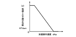
同様に、より適切に過渡的なトルクステアを低減するため、図14及び図15に示すように加速操作速度dApに応じて上記の各パラメータを設定することにより、トルクステア低減トルク目標値Ttsを、加速操作速度dApに応じて以下のように決定することができる。尚、以下の(a)、(b)、(c)及び(d)は、図14及び図15における縦軸のパラメータ(a)、(b)、(c)及び(d)に夫々対応している。但し、図14の縦軸の各パラメータについても、図12と同様、スケールが一致することを表すものではない。 Similarly, in order to reduce the transient torque steer more appropriately, the torque steer reduction torque target value Tts is set by setting each of the above parameters according to the acceleration operation speed dAp as shown in FIGS. Depending on the acceleration operation speed dAp, it can be determined as follows. The following (a), (b), (c) and (d) correspond to the parameters (a), (b), (c) and (d) on the vertical axis in FIGS. 14 and 15, respectively. ing. However, the parameters on the vertical axis in FIG. 14 do not indicate that the scales are the same as in FIG.
(a)加速操作速度dApが大きいときには、トルクステア低減トルク目標値Ttsの増加勾配KTupを大きく設定し、トルクステア低減トルクを速やかに立ち上げるようにすることができる。
(b)加速操作速度dApが大きいときには、トルクステア低減トルク目標値Ttsの最大値Ttsmを大きく設定して、トルクステア低減トルクをより大きく与えるようにすることができる。
(c)加速操作速度dApが大きいときには、トルクステア低減トルク目標値Ttsの最大値Ttsmの保持時間Thldを長く設定して、トルクステア低減トルクを充分に与えるようにすることができる。
(d)加速操作速度dApが大きいときには、トルクステア低減トルク目標値Ttsの減少勾配KTdwnを小さく設定して、トルクステア低減トルクを緩やかに立ち下げるようにすることができる。
(A) When the acceleration operation speed dAp is high, the increase gradient KTup of the torque steer reduction torque target value Tts can be set large so that the torque steer reduction torque can be quickly started up.
(B) When the acceleration operation speed dAp is high, the maximum value Ttsm of the torque steer reduction torque target value Tts can be set to be large so that the torque steer reduction torque can be given more.
(C) When the acceleration operation speed dAp is high, the holding time Thld of the maximum value Ttsm of the torque steer reduction target torque value Tts can be set long so that the torque steer reduction torque can be sufficiently applied.
(D) When the acceleration operation speed dAp is large, the decrease gradient KTdwn of the torque steer reduction torque target value Tts can be set small, so that the torque steer reduction torque can be gradually lowered.
次に、図4のステップ203におけるトルクステア低減制御終了条件は、図16に示すように行われる。先ず、ステップ501においてトルクステア低減トルク目標値Ttsがゼロか否かが判定される。既に加速操作量Apが所定値Ap1以上であったとしても、制御開始時に与えられたパルス波形において、トルクステア低減トルク目標値Ttsがゼロとなった場合には、ステップ504に進み、トルクステア低減制御は終了する。また、トルクステア低減トルク目標値Ttsのパルス波形がゼロとなっていない場合でも、ステップ502において、加速操作量Apが所定値Ap2未満となって車両の加速状態が低くなったと判定された場合、あるいは、ステップ503において、変速機TRがシフトアップされて変速比Rtが所定値Rt2より小さくなったと判定された場合には、ステップ504に進み、トルクステア低減制御は終了する。尚、これらの終了条件を充足した場合には、トルクステア低減トルク目標値Ttsを急激にゼロに低下させるのではなく、減少勾配の閾値を設け、徐々に低下させるように設定することができる。これにより、ステアリングホイールSWに対する急激な操舵トルク変動を回避することができる。
Next, the torque steer reduction control ending condition in
以上の実施形態では、運転者の加速操作は、アクセルペダルAPの操作量によって検出することとしているが、前述のように、加速操作は、運転者の操作から駆動力を発生する動力源への入力までにおいて何れかの個所で検出することができる。従って、加速操作はアクセルペダルの操作に限定されるのではない。例えば、スロットル開度、燃料の噴射量、電気モータの駆動電流・電圧等を用いて、運転者の加速操作を検出することができる。 In the above embodiment, the driver's acceleration operation is detected by the operation amount of the accelerator pedal AP. As described above, the acceleration operation is performed from the driver's operation to a power source that generates driving force. It can be detected at any point until the input. Therefore, the acceleration operation is not limited to the operation of the accelerator pedal. For example, the driver's acceleration operation can be detected using the throttle opening, the fuel injection amount, the drive current / voltage of the electric motor, and the like.
ドライブシャフトDS1及びDS2の特性は、予め把握することが可能であり、運転者の加速操作が所定値以上となったときに、ドライブシャフトの特性差に起因する過渡的なトルクステアを低減する操舵トルクをステアリングホイールに付与し、車両の加速時において運転者の操舵違和感を低減することができる。また、付与されるトルクステア低減トルクは、固定の、又は、加速操作に応じたパルス波形として決定されるため、車輪の駆動力を検出・推定することを必要としない。更に、トルクステア低減制御の実行においては、変速機の変速比が考慮されるため、不必要なときにトルクステア低減トルクが付与されることはなく、運転者に対し違和感を与えることがない。 The characteristics of the drive shafts DS1 and DS2 can be grasped in advance, and steering that reduces transient torque steer due to the difference in characteristics of the drive shaft when the driver's acceleration operation exceeds a predetermined value. Torque can be applied to the steering wheel to reduce the driver's uncomfortable feeling during acceleration of the vehicle. Further, since the applied torque steer reduction torque is determined as a fixed or pulse waveform corresponding to the acceleration operation, it is not necessary to detect and estimate the driving force of the wheels. Further, in executing the torque steer reduction control, the transmission gear ratio is taken into consideration, so that the torque steer reduction torque is not applied when unnecessary, and the driver does not feel uncomfortable.
上記のように過渡的なトルクステアを低減することによって、車両の加速時に発生する、操向車輪がステアリングホイールを転舵しようとするトルクステアを、効果的に低減することができる。また、過渡的なトルクステアは、主として車両の発進加速時に発生するので、前述のように、車両の発進加速時(車両の速度が略ゼロで、加速操作が所定値以上のとき)にトルクステア低減制御を実行することにより、ドライブシャフトの特性に起因する過渡的なトルクステアを、効果的に低減することができる。 By reducing the transient torque steer as described above, it is possible to effectively reduce the torque steer that the steered wheel tries to steer the steering wheel, which occurs during acceleration of the vehicle. Since transient torque steer occurs mainly at the time of start acceleration of the vehicle, as described above, torque steer at the time of vehicle start acceleration (when the vehicle speed is substantially zero and the acceleration operation is equal to or greater than a predetermined value). By executing the reduction control, the transient torque steer due to the characteristics of the drive shaft can be effectively reduced.
M1 操舵トルク検出手段
M2 パワーステアリング補助トルク目標値決定手段
M3 加速操作検出手段
M4 判定手段
M5 トルクステア低減トルク目標値決定手段
M6 モータ駆動制御手段
M7 変速機状態検出手段
M8 車両速度検出手段
ECU1 エンジン電子制御ユニット
ECU2 ステアリング電子制御ユニット
ECU3 変速機電子制御ユニット
ECU4 ブレーキ電子制御ユニット
SW ステアリングホイール
MT 電気モータ
EG エンジン
TR 変速機
WHfr,WHfl 車輪
AP アクセルペダルセンサ
TS 操舵トルクセンサ
TK スロットル開度センサ
M1 Steering torque detection means M2 Power steering assist torque target value determination means M3 Acceleration operation detection means M4 Determination means M5 Torque steer reduction torque target value determination means M6 Motor drive control means M7 Transmission state detection means M8 Vehicle speed detection means ECU1 Engine electronics Control unit ECU2 Steering electronic control unit ECU3 Transmission electronic control unit ECU4 Brake electronic control unit SW Steering wheel MT Electric motor EG Engine TR Transmission WHfr, WHfl Wheel AP Accelerator pedal sensor TS Steering torque sensor TK Throttle opening sensor
Claims (6)
Priority Applications (4)
| Application Number | Priority Date | Filing Date | Title |
|---|---|---|---|
| JP2006165663A JP4835986B2 (en) | 2006-06-15 | 2006-06-15 | Electric steering control device |
| US11/760,082 US7743874B2 (en) | 2006-06-15 | 2007-06-08 | Steering control apparatus for a vehicle |
| DE102007000320A DE102007000320B4 (en) | 2006-06-15 | 2007-06-12 | Steering control device for a vehicle |
| CN2007101107684A CN101088829B (en) | 2006-06-15 | 2007-06-13 | Steering control apparatus for a vehicle |
Applications Claiming Priority (1)
| Application Number | Priority Date | Filing Date | Title |
|---|---|---|---|
| JP2006165663A JP4835986B2 (en) | 2006-06-15 | 2006-06-15 | Electric steering control device |
Publications (2)
| Publication Number | Publication Date |
|---|---|
| JP2007331565A JP2007331565A (en) | 2007-12-27 |
| JP4835986B2 true JP4835986B2 (en) | 2011-12-14 |
Family
ID=38862590
Family Applications (1)
| Application Number | Title | Priority Date | Filing Date |
|---|---|---|---|
| JP2006165663A Expired - Fee Related JP4835986B2 (en) | 2006-06-15 | 2006-06-15 | Electric steering control device |
Country Status (4)
| Country | Link |
|---|---|
| US (1) | US7743874B2 (en) |
| JP (1) | JP4835986B2 (en) |
| CN (1) | CN101088829B (en) |
| DE (1) | DE102007000320B4 (en) |
Families Citing this family (14)
| Publication number | Priority date | Publication date | Assignee | Title |
|---|---|---|---|---|
| US8473165B2 (en) * | 2007-10-18 | 2013-06-25 | Sumitomo Heavy Industries, Ltd. | Turning drive control apparatus and construction machine including the same |
| US8452493B2 (en) * | 2008-01-25 | 2013-05-28 | Steering Solutions Ip Holding Corporation | Methods and systems involving return torque |
| US7874564B2 (en) * | 2008-04-28 | 2011-01-25 | Honda Motor Co., Ltd. | Torque steer reduction system |
| EP2323890B1 (en) * | 2008-09-10 | 2012-09-05 | Continental Teves AG & Co. oHG | Method for steering assistance during emergency manoeuvres |
| US8831854B2 (en) * | 2010-08-16 | 2014-09-09 | Chrysler Group Llc | Active shimmy mitigation |
| US8589027B2 (en) * | 2010-12-02 | 2013-11-19 | Furuno Electric Company Limited | Steering assist system and method using autopilot device |
| US8897966B2 (en) | 2011-05-12 | 2014-11-25 | Carlos A. Saez | Methods and apparatus for variable reduced effort steering in electric steering systems |
| EP2851267B1 (en) * | 2012-05-16 | 2016-05-11 | Nissan Motor Co., Ltd | Vehicle steering control device and steering control method |
| CN106697048B (en) * | 2015-11-12 | 2019-05-03 | 株式会社万都 | For compensating the electronic control unit and method of torque steering |
| DE112015007247B4 (en) | 2015-12-28 | 2022-02-10 | Mitsubishi Electric Corporation | STEERING CONTROL UNIT FOR A VEHICLE |
| KR102532338B1 (en) * | 2018-06-21 | 2023-05-16 | 현대자동차주식회사 | Steering control method for vehicles |
| FR3083772B1 (en) | 2018-07-13 | 2020-08-28 | Jtekt Europe Sas | PROGRESSIVE DETECTION OF THE APPEARANCE OF A DRAFT TORQUE PHENOMENON |
| CN109131540A (en) * | 2018-08-28 | 2019-01-04 | 北京汽车股份有限公司 | Compensation method, device and the vehicle of steering-wheel torque |
| EP3753807A1 (en) * | 2019-06-17 | 2020-12-23 | Volvo Car Corporation | Improved control of electrical power steering |
Family Cites Families (18)
| Publication number | Priority date | Publication date | Assignee | Title |
|---|---|---|---|---|
| US4509611A (en) * | 1983-10-13 | 1985-04-09 | General Motors Corporation | Adaptive controller for electric power steering |
| JPS60145968A (en) * | 1983-12-29 | 1985-08-01 | 黒崎窯業株式会社 | Lining joint filler for molten metal vessel |
| JPS60145966A (en) * | 1984-01-07 | 1985-08-01 | トヨタ自動車株式会社 | Method of dewaxing ceramic injection formed body |
| JPS62182873A (en) * | 1986-02-05 | 1987-08-11 | Shin Nikkei Co Ltd | Plotting system for fitting |
| JPS6317177A (en) * | 1986-07-09 | 1988-01-25 | Toyota Motor Corp | Power steering device |
| JPS6391976A (en) * | 1986-10-03 | 1988-04-22 | オムロン株式会社 | Terminal base apparatus |
| JP3046108B2 (en) * | 1991-08-26 | 2000-05-29 | 富士重工業株式会社 | Steering force control method for vehicle with differential limiting device |
| JP3010838B2 (en) | 1991-09-18 | 2000-02-21 | 三菱自動車工業株式会社 | Left and right driving force distribution device for vehicles |
| JP3095961B2 (en) * | 1994-10-04 | 2000-10-10 | 本田技研工業株式会社 | Steering reaction force control device for vehicle steering system |
| US6032755A (en) * | 1996-01-30 | 2000-03-07 | Trw Inc. | Method and apparatus for compensating torque steer |
| JP3105847B2 (en) | 1997-11-04 | 2000-11-06 | 本田技研工業株式会社 | Steering wheel control structure for electrically steered vehicles |
| GB2369332A (en) * | 2000-11-22 | 2002-05-29 | Trw Lucasvarity Electric Steer | Compensation for motor inertia in electric power-assisted steering systems |
| US6909958B2 (en) * | 2003-05-12 | 2005-06-21 | Honda Giken Kogyo Kabushiki Kaisha | System and method for inhibiting torque steer |
| JP4300103B2 (en) * | 2003-12-09 | 2009-07-22 | 株式会社日立製作所 | Vehicle steering control device |
| JP4400270B2 (en) * | 2004-03-19 | 2010-01-20 | 日産自動車株式会社 | Steering angle ratio control device for vehicle |
| US7532966B2 (en) * | 2004-08-20 | 2009-05-12 | General Motors Corporation | Torque steer compensation algorithm |
| JP4626290B2 (en) * | 2004-12-14 | 2011-02-02 | 日産自動車株式会社 | Vehicle deflection suppression device |
| JP2007245768A (en) * | 2006-03-13 | 2007-09-27 | Nissan Motor Co Ltd | Steering device, automobile, and steering control method |
-
2006
- 2006-06-15 JP JP2006165663A patent/JP4835986B2/en not_active Expired - Fee Related
-
2007
- 2007-06-08 US US11/760,082 patent/US7743874B2/en not_active Expired - Fee Related
- 2007-06-12 DE DE102007000320A patent/DE102007000320B4/en not_active Expired - Fee Related
- 2007-06-13 CN CN2007101107684A patent/CN101088829B/en not_active Expired - Fee Related
Also Published As
| Publication number | Publication date |
|---|---|
| CN101088829B (en) | 2011-09-07 |
| DE102007000320A8 (en) | 2009-04-23 |
| US20070294008A1 (en) | 2007-12-20 |
| JP2007331565A (en) | 2007-12-27 |
| CN101088829A (en) | 2007-12-19 |
| DE102007000320B4 (en) | 2012-08-09 |
| US7743874B2 (en) | 2010-06-29 |
| DE102007000320A1 (en) | 2008-12-18 |
Similar Documents
| Publication | Publication Date | Title |
|---|---|---|
| JP4835986B2 (en) | Electric steering control device | |
| US7970513B2 (en) | Steering control apparatus for a vehicle | |
| JP6162762B2 (en) | Vehicle control apparatus and vehicle control method | |
| US7647149B2 (en) | Control device for electric power steering system of vehicle having wheel slip control system active on steered vehicle wheels | |
| US10272943B2 (en) | Control unit for vehicle and control method for vehicle | |
| US10689028B2 (en) | Control apparatus and method of motor-driven power steering system | |
| US20110259663A1 (en) | Steering apparatus for vehicle | |
| JP4853122B2 (en) | Electric steering control device | |
| JP2000085604A (en) | Steering control device | |
| JP6329308B2 (en) | Vehicle control apparatus and vehicle control method | |
| JP2017108485A (en) | Vehicle control device and vehicle control method | |
| JP5454688B2 (en) | Vehicle left and right wheel driving force distribution control device | |
| EP3056409B1 (en) | Torque steering mitigation for electric power steering | |
| EP3656648B1 (en) | Apparatus and method for controlling steering system of vehicle | |
| US20120253622A1 (en) | Control device for controlling drive force that operates on vehicle | |
| JP2007331566A (en) | Electric steering control device | |
| JP4910491B2 (en) | Electric steering control device | |
| JP2007331569A (en) | Electric steering control device | |
| JPH11268552A (en) | Turning assist device for vehicle | |
| JP5119691B2 (en) | Steering control device | |
| JP5862516B2 (en) | Vehicle control device |
Legal Events
| Date | Code | Title | Description |
|---|---|---|---|
| A621 | Written request for application examination |
Free format text: JAPANESE INTERMEDIATE CODE: A621 Effective date: 20081210 |
|
| A977 | Report on retrieval |
Free format text: JAPANESE INTERMEDIATE CODE: A971007 Effective date: 20110425 |
|
| A131 | Notification of reasons for refusal |
Free format text: JAPANESE INTERMEDIATE CODE: A131 Effective date: 20110510 |
|
| A521 | Written amendment |
Free format text: JAPANESE INTERMEDIATE CODE: A523 Effective date: 20110709 |
|
| TRDD | Decision of grant or rejection written | ||
| A01 | Written decision to grant a patent or to grant a registration (utility model) |
Free format text: JAPANESE INTERMEDIATE CODE: A01 Effective date: 20110902 |
|
| A01 | Written decision to grant a patent or to grant a registration (utility model) |
Free format text: JAPANESE INTERMEDIATE CODE: A01 |
|
| A61 | First payment of annual fees (during grant procedure) |
Free format text: JAPANESE INTERMEDIATE CODE: A61 Effective date: 20110915 |
|
| FPAY | Renewal fee payment (event date is renewal date of database) |
Free format text: PAYMENT UNTIL: 20141007 Year of fee payment: 3 |
|
| R150 | Certificate of patent or registration of utility model |
Free format text: JAPANESE INTERMEDIATE CODE: R150 |
|
| LAPS | Cancellation because of no payment of annual fees |