JP4835179B2 - Ball screw device - Google Patents
Ball screw device Download PDFInfo
- Publication number
- JP4835179B2 JP4835179B2 JP2006024897A JP2006024897A JP4835179B2 JP 4835179 B2 JP4835179 B2 JP 4835179B2 JP 2006024897 A JP2006024897 A JP 2006024897A JP 2006024897 A JP2006024897 A JP 2006024897A JP 4835179 B2 JP4835179 B2 JP 4835179B2
- Authority
- JP
- Japan
- Prior art keywords
- seal
- nut
- ball screw
- raceway groove
- screw device
- Prior art date
- Legal status (The legal status is an assumption and is not a legal conclusion. Google has not performed a legal analysis and makes no representation as to the accuracy of the status listed.)
- Active
Links
Images


Description
本発明は、工作機械や産業機械、半導体製造装置、射出成形機、プレス成形機、精密機械等の機械装置の移動台の位置決め用や搬送用、動力伝達用の送り機構等に用いられるボールねじ装置に関する。 The present invention relates to a ball screw used for a feed mechanism for positioning, conveying, and power transmission of a moving table of a machine device such as a machine tool, an industrial machine, a semiconductor manufacturing apparatus, an injection molding machine, a press molding machine, or a precision machine. Relates to the device.
従来のボールねじ装置は、ねじ軸の外周面に螺旋状に形成した軸軌道溝と、ナットの内周面に形成した軸軌道溝に対向するナット軌道溝とを複数のボールを介して螺合させ、そのねじ軸の軸直角断面(ねじ軸の軸芯が鉛直線となる断面をいう。)の形状に所定のシール代を持たせた相似形状の内周縁を有する薄板平板状の2枚のシール板をスペーサを介して平行に配置し、これをナットの軸方向の両端部に、シール板をねじ軸の軸直角断面と平行にしてその内周縁を軸軌道溝およびねじ軸の外周面に摺接させて設置し、接触式のシールを構成してナットの内部への塵芥等の異物の侵入を防止している(例えば、特許文献1参照。)。
しかしながら、上述した従来の技術においては、シール板をねじ軸の軸直角断面と平行にして、所定のシール代を持たせた内周縁を軸軌道溝およびねじ軸の外周面に摺接させているため、図7に示すようにシール板Aの内周縁が摺接するねじ軸2の軸軌道溝3の溝底を境にしてシール板Aの内周縁の軸方向に捲れ返る方向が異なり、ナットの内側(図7に示すB方向)に向かって捲れ返った内周縁から異物が内部に侵入しやすくなり、シール板Aのシール性を損なう虞があるという問題がある。
However, in the above-described conventional technology, the seal plate is parallel to the cross section perpendicular to the axis of the screw shaft, and the inner peripheral edge having a predetermined seal allowance is brought into sliding contact with the shaft raceway groove and the outer peripheral surface of the screw shaft. Therefore, as shown in FIG. 7, the direction of turning back in the axial direction of the inner peripheral edge of the seal plate A at the groove bottom of the
このことは、ナットの一端に2枚のシール板を並設した場合においても同様である。
本発明は、上記の問題点を解決するためになされたもので、シール板の内周縁の捲れ返る方向を安定させてシール性を向上させる手段を提供することを目的とする。
The same applies to the case where two seal plates are arranged in parallel at one end of the nut.
The present invention has been made to solve the above-described problems, and an object of the present invention is to provide means for improving the sealing performance by stabilizing the turning direction of the inner peripheral edge of the seal plate.
本発明は、上記課題を解決するために、外周面に螺旋状の軸軌道溝を形成したねじ軸と、内周面に前記軸軌道溝に対向するナット軌道溝を形成したナットと、前記軸軌道溝とナット軌道溝とを螺合させる複数のボールと、前記ナットの軸方向の端部に設置され、前記ねじ軸の軸直角断面形状と相似の内周縁形状を有するシール板とを備えたボールねじ装置において、弾性材の薄板からなる前記シール板の円周方向の一箇所に、半径方向に沿った切断部を設け、前記シール板の全体形状を、円錐台形状に形成したことを特徴とする。 In order to solve the above problems, the present invention provides a screw shaft in which a spiral shaft raceway groove is formed on an outer peripheral surface, a nut in which a nut raceway groove facing the shaft raceway groove is formed on an inner peripheral surface, and the shaft A plurality of balls for screwing the raceway groove and the nut raceway groove, and a seal plate installed at an axial end of the nut and having an inner peripheral edge shape similar to the axially perpendicular cross-sectional shape of the screw shaft In the ball screw device, a cut portion along a radial direction is provided at one place in a circumferential direction of the seal plate made of a thin plate of an elastic material, and the entire shape of the seal plate is formed in a truncated cone shape. And
これにより、本発明は、シール板の内周縁の捲れ返る方向を全てナットの軸方向の外側に向かう方向とすることができ、ナットの外部から侵入する異物に対するシール板のシール性を向上させることができるという効果が得られる。 Thereby, this invention can make all the directions where the inner periphery of a sealing plate turns back to the direction which goes to the outer side of the axial direction of a nut, and improves the sealing performance of the sealing plate with respect to the foreign material which penetrate | invades from the nut exterior The effect of being able to be obtained.
以下に、図面を参照して本発明によるボールねじ装置の実施例について説明する。 Embodiments of a ball screw device according to the present invention will be described below with reference to the drawings.
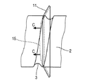
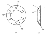
図1は実施例1のボールねじ装置の断面を示す説明図、図2は実施例1のシール板を示す説明図である。
図1において、1はボールねじ装置である。
2はボールねじ装置1のねじ軸であり、合金鋼等の鋼材で製作された棒状部材であって、その外周面には略半円弧状断面形状の軸軌道溝3が所定のリードで螺旋状に形成されている。
FIG. 1 is an explanatory view showing a cross section of the ball screw device of the first embodiment, and FIG. 2 is an explanatory view showing a seal plate of the first embodiment.
In FIG. 1, 1 is a ball screw device.
4はボールねじ装置1のナットであり、合金鋼等の鋼材で製作された円筒状部材であって、その内周面には軸軌道溝3と対向する略半円弧状断面形状のナット軌道溝5が軸軌道溝3と同じリードで形成されている。
6はフランジ部であり、ナット4の外周部の一方の端部に設けられ、フランジ部6に設けられた図示しないボルト穴等により図示しない機械装置の移動台にボルト等で固定される。
7はボールであり、合金鋼等の鋼材で製作された球体であって、対向配置された軸軌道溝3とナット軌道溝5とで形成される負荷路を転動してねじ軸2とナット4を螺合させる。
11はシール板であり、合成ゴム、合成樹脂、合成繊維等の弾性を有する弾性材の薄板で、ナット4の軸方向(単に、軸方向という。)の外側に向かって縮小する円錐台形状に形成された皿状の円環部材であって、図2に示すように、その円周方向の一箇所に半径方向に沿う切断部12が設けられており、切断部12の端面を突合させて円錐台形状を形成するように構成され、取付ボルト13を挿通させる軸方向に沿った取付穴14が所定のピッチ円直径、角度ピッチで複数形成されている。
また、シール板11の内周縁15は、図1に示すように、ナット4の両端部に設置したときに、内周縁15が摺接するねじ軸2の部位の軸直角断面の形状に所定のシール代を持たせた相似形状に形成されている(図2(a)参照)。
18、19はシール取付板であり、合金鋼等の鋼材で製作されたナット4の内周面の直径と同等の内径を有する円盤状部材であって、取付ボルト13を挿通させるボルト穴がシール板11の取付穴14と同じピッチ円直径、角度ピッチで形成されている。
Further, as shown in FIG. 1, the inner
シール取付板18の一方の端面には、シール板11の円錐面に沿った軸方向外側に凸の底面を有し、シール板11の厚さから所定の締め代を減じた深さを有するシール嵌合穴18aが設けられ、シール取付板19のシール取付板18側の面には、シール嵌合穴18aの底面に対向する円錐面が形成されている。
20は嵌合穴であり、ナット4の軸方向の両側の端部に形成されたシール取付板18、19の外周面が嵌合する穴である。
One end face of the
上記の軸軌道溝3とナット軌道溝5とで形成される負荷路の両端部は、図示しない連通路としてのリターンチューブにより連通されて循環路が形成され、この循環路には複数のボール7と所定の量の潤滑剤、例えばグリースが封入され、軸軌道溝3とナット軌道溝6とがボール7を介して螺合し、ねじ軸2の回転に伴ってボール7が循環路を循環し、負荷路を転動するボール7がナット4に加えられた荷重を往復動自在に支持してナット4がねじ軸2の長手方向に沿った直線往復移動可能に支持される。これによりねじ軸2の回転運動がナット4の直線運動に変換される。
Both ends of the load path formed by the
上記のシール板11は、切断部12の端面を突合させて円錐台形状とし、これをシール取付板18のシール嵌合穴18aに嵌め込み、シール嵌合穴18aの底面とシール取付板19に形成された円錐面とで挟み込んだ後に、取付ボルト13でナット4の両端部の嵌合穴20の底面に固定される。
これにより、シール板11の内周縁15が、ねじ軸2の軸軌道溝3および外周面に摺接する接触式のシールとして機能する。
The
Thereby, the inner
このようにして設置されたシール板11は、図3に示すように、ねじ軸2の軸直角断面に対して軸方向の外側に向けて傾いているので、全ての内周縁15がナット4の軸方向の外側に捲れ返り、ナット4の外部からの異物の侵入に対するシール性が損なわれることはない。
以上説明したように、本実施例では、シール板をナットの軸方向の外側に向かって縮小する円錐台形状に形成したことことによって、シール板の内周縁の捲れ返る方向を全てナットの軸方向の外側に向かう方向とすることができ、シール板のシール性を向上させてナットの外部からの異物の侵入を確実に防止することができる。
As shown in FIG. 3, the
As described above, in this embodiment, the seal plate is formed in a truncated cone shape that decreases toward the outer side in the axial direction of the nut, so that all the turning directions of the inner peripheral edge of the seal plate are turned in the axial direction of the nut. The direction toward the outer side of the nut can be improved, and the sealing performance of the seal plate can be improved, and the entry of foreign matter from the outside of the nut can be reliably prevented.
また、シール板の円周方向の一箇所に半径方向に沿った切断部を設けたことによって、円錐台形状の側面を平らに展開した扇型状のシール板を形成すれば、その切断部の端面を突合わせて円錐台形状のシール板を容易に形成することができる。
なお、本実施例においては、ナットの両端部にそれぞれ1枚のシール板を設置するとして説明したが、複数のシール板を軸方向に重ねて設置するようにしてもよい。
In addition, if a fan-shaped seal plate with a flat frustum-shaped side surface is formed by providing a cut portion along the radial direction at one place in the circumferential direction of the seal plate, A frustoconical seal plate can be easily formed by abutting the end faces.
In the present embodiment, it has been described that one seal plate is installed at each end of the nut. However, a plurality of seal plates may be installed in the axial direction.
この場合に、それぞれのシール板の切断部の円周方向の角度位置をずらせて重ねれば、切断部の隙間からの異物の侵入を更に有効に防止することができる。
また、本実施例においては、シール板の切断部の端面を突合わせて円錐台形状のシール板を形成するとして説明したが、図4に示すようにシール板11の切断部12の一端を、他端に重ね合わせるようにしてもよい。このようにすれば切断部12の端面の寸法精度を緩やかにすることが可能になり、円錐台形状のシール板11を更に容易に形成することができる。
In this case, if the angular positions in the circumferential direction of the cut portions of the respective seal plates are shifted and overlapped, it is possible to more effectively prevent foreign matters from entering through the gaps in the cut portions.
In the present embodiment, the end face of the cut portion of the seal plate is abutted to form a truncated cone-shaped seal plate, but one end of the
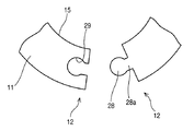
図5は実施例2のシール板の切断部の形状を示す説明図である。
なお、上記実施例1と同様の部分は、同一の符号を付してその説明を省略する。
図5において、25はシール板11の切断部12の一端に形成された凸部であり、他端に形成された凹部26に嵌合する形状に形成されている。
このような切断部12の形状を有するシール板11は、一方の切断部12の凸部25を他方の切断部12の凹部26に嵌合させて円錐台形状とし、これをシール取付板18のシール嵌合穴18aに嵌め込み、シール嵌合穴18aの底面とシール取付板19に形成された円錐面とで挟み込んだ後に、取付ボルト13でナット4の両端部の嵌合穴20の底面に締結して固定される。
FIG. 5 is an explanatory view showing the shape of the cut portion of the seal plate of the second embodiment.
In addition, the same part as the said Example 1 attaches | subjects the same code | symbol, and abbreviate | omits the description.
In FIG. 5,
The
このようにすれば、上記実施例1と同様の効果に加えて、一方の切断部の凸部を他方の切断部の凹部に嵌合させて円錐台形状のシール板を形成することができ、シール板をシール嵌合穴に嵌め込むときに、シール板の切断部同士の半径方向のずれを防止してシール板の組付性を向上させることができる。
なお、上記の凸部と凹部の形状を、図6に示す形状としてもよい。
In this way, in addition to the same effects as in the first embodiment, the convex part of one cutting part can be fitted into the concave part of the other cutting part to form a frustoconical sealing plate, When the seal plate is fitted into the seal fitting hole, the radial displacement between the cut portions of the seal plate can be prevented to improve the assembling property of the seal plate.
Note that the shapes of the convex portions and the concave portions may be the shapes shown in FIG.
図6において、28は凸状の鍵部であり、シール板の一方の切断部12に形成された先端部の円形状が首部28aより広がった形状に形成されており、他端に形成された凹状の鍵部29に嵌合する形状に形成されている。
この場合に、凸状の鍵部28の先端部の形状は、三角形や矩形であってもよい。要は首部28aより広がった形状であればどのような形状であってもよい。
In FIG. 6, 28 is a convex key part, and the circular shape of the tip part formed in one
In this case, the shape of the tip of the
このような切断部12の形状を有するシール板11は、一方の切断部12の凸状の鍵部28を他方の切断部12の凹状の鍵部29に嵌合させて円錐台形状とし、これをシール取付板18のシール嵌合穴18aに嵌め込み、シール嵌合穴18aの底面とシール取付板19に形成された円錐面とで挟み込んだ後に、取付ボルト13でナット4の両端部の嵌合穴20の底面に締結して固定される。
The
このようにすれば、上記の効果に加えて、一方の切断部の凸状の鍵部を他方の切断部の凹状の鍵部に嵌合させて円錐台形状のシール板を形成したときに、その形状を容易に保つことができ、シール板をシール嵌合穴に嵌め込むときの組付性を更に向上させることができる。
なお、上記各実施例においては、シール板11を2枚のシール取付板18、19で挟みつけて固定するとして説明したが、例えば、シール取付板19にシール板11を焼付けて一体に成形するようにし、シール板18を省略するようにしてもよい。
In this way, in addition to the above-mentioned effect, when the convex key part of one cutting part is fitted to the concave key part of the other cutting part to form a frustoconical seal plate, The shape can be easily maintained, and the assemblability when the seal plate is fitted into the seal fitting hole can be further improved.
In each of the above embodiments, the
また、上記各実施例においては、リターンチューブを連通路としてボールを循環させるチューブ式の循環方式を用いたボールねじ装置に本発明を適用した場合を例に説明したが、連通路は前記に限らず、連通路をこま式やエンドキャップ式、デフレクタ式等とした循環方式のボールねじ装置に本発明を適用しても同様の効果を得ることができる。
更に、上記各実施例においては、ボールねじ装置のねじ軸を回転させてナットを軸方向に移動させるとして説明したが、ナットを回転させてねじ軸を軸方向に移動させる形式のボールねじ装置に本発明を適用しても同様の効果を得ることができる。
In each of the above embodiments, the case where the present invention is applied to a ball screw device using a tube-type circulation system in which a ball is circulated using a return tube as a communication path has been described as an example. However, the communication path is not limited to the above. The same effect can be obtained even if the present invention is applied to a circulation type ball screw device in which the communication path is a top type, an end cap type, a deflector type or the like.
Further, in each of the above embodiments, the screw shaft of the ball screw device is rotated and the nut is moved in the axial direction. However, in the ball screw device of the type in which the nut is rotated and the screw shaft is moved in the axial direction. The same effect can be obtained even when the present invention is applied.
1 ボールねじ装置
2 ねじ軸
3 軸軌道溝
4 ナット
5 ナット軌道溝
6 フランジ部
7 ボール
11 シール板
12 切断部
13 取付ボルト
14 取付穴
15 内周縁
18、19 シール取付板
18a シール嵌合穴
20 嵌合穴
25 凸部
26 凹部
28 凸状の鍵部
28a 首部
29 凹状の鍵部
DESCRIPTION OF SYMBOLS 1
Claims (6)
弾性材の薄板からなる前記シール板の円周方向の一箇所に、半径方向に沿った切断部を設け、
前記シール板の全体形状を、円錐台形状に形成したことを特徴とするボールねじ装置。 A screw shaft having a spiral shaft raceway groove formed on the outer peripheral surface, a nut having a nut raceway groove facing the shaft raceway groove on the inner peripheral surface, and a plurality of screwing the shaft raceway groove and the nut raceway groove. A ball screw device including a ball and a seal plate that is installed at an end portion in the axial direction of the nut and has an inner peripheral edge shape similar to the axially perpendicular cross-sectional shape of the screw shaft,
In one place in the circumferential direction of the sealing plate made of a thin plate of elastic material, a cutting portion along the radial direction is provided,
A ball screw device characterized in that the overall shape of the sealing plate is formed in a truncated cone shape.
前記シール板の切断部の一端を、他端に重ね合わせたことを特徴とするボールねじ装置。 In claim 1,
A ball screw device, wherein one end of the cut portion of the seal plate is overlapped with the other end.
前記シール板の切断部の一端に凸部を形成し、他端に該凸部に嵌合する凹部を形成したことを特徴とするボールねじ装置。 In claim 1,
A ball screw device, wherein a convex portion is formed at one end of the cut portion of the seal plate, and a concave portion is formed at the other end to be fitted to the convex portion.
前記シール板の切断部の一端に、先端部が首部より広がった凸状の鍵部を形成し、他端に該凸状の鍵部に嵌合する凹状の鍵部を形成したことを特徴とするボールねじ装置。 In claim 1,
A convex key portion having a tip portion wider than a neck portion is formed at one end of the cut portion of the seal plate, and a concave key portion that is fitted to the convex key portion is formed at the other end. Ball screw device to do.
前記シール板を、複数重ねて設置したことを特徴とするボールねじ装置。 In any one of Claims 1 thru | or 4,
A ball screw device in which a plurality of the seal plates are stacked.
前記複数のシール板の切断部の位置を、円周方向にずらせて重ねたことを特徴とするボールねじ装置。 In claim 5,
A ball screw device in which the positions of the cut portions of the plurality of seal plates are overlapped while being shifted in the circumferential direction.
Priority Applications (1)
| Application Number | Priority Date | Filing Date | Title |
|---|---|---|---|
| JP2006024897A JP4835179B2 (en) | 2006-02-01 | 2006-02-01 | Ball screw device |
Applications Claiming Priority (1)
| Application Number | Priority Date | Filing Date | Title |
|---|---|---|---|
| JP2006024897A JP4835179B2 (en) | 2006-02-01 | 2006-02-01 | Ball screw device |
Publications (3)
| Publication Number | Publication Date |
|---|---|
| JP2007205462A JP2007205462A (en) | 2007-08-16 |
| JP2007205462A5 JP2007205462A5 (en) | 2009-03-05 |
| JP4835179B2 true JP4835179B2 (en) | 2011-12-14 |
Family
ID=38485102
Family Applications (1)
| Application Number | Title | Priority Date | Filing Date |
|---|---|---|---|
| JP2006024897A Active JP4835179B2 (en) | 2006-02-01 | 2006-02-01 | Ball screw device |
Country Status (1)
| Country | Link |
|---|---|
| JP (1) | JP4835179B2 (en) |
Families Citing this family (6)
| Publication number | Priority date | Publication date | Assignee | Title |
|---|---|---|---|---|
| JP5256204B2 (en) * | 2007-09-28 | 2013-08-07 | Thk株式会社 | Rolling device |
| JP2011169377A (en) * | 2010-02-17 | 2011-09-01 | Nsk Ltd | Seal member, ball screw having seal member, and method for manufacturing seal member |
| US9423012B2 (en) * | 2011-10-24 | 2016-08-23 | Nsk Ltd. | Ball screw device and dust-proof member extracting tool |
| CN104791445B (en) * | 2014-01-17 | 2018-03-13 | 上银科技股份有限公司 | Ball screw with scraping brushing device |
| JP2017002963A (en) * | 2015-06-08 | 2017-01-05 | 日本精工株式会社 | Ball Screw |
| CN215634779U (en) | 2021-08-06 | 2022-01-25 | 李思颖 | Linear transmission device and assembly thereof |
Family Cites Families (7)
| Publication number | Priority date | Publication date | Assignee | Title |
|---|---|---|---|---|
| JPH0645577B2 (en) * | 1986-06-10 | 1994-06-15 | 住友化学工業株式会社 | Method for producing optically active amines |
| JP3692203B2 (en) * | 1997-03-10 | 2005-09-07 | 日本精工株式会社 | Seal for ball screw |
| JP4322988B2 (en) * | 1999-02-12 | 2009-09-02 | 株式会社阪上製作所 | Seal member for ball screw device |
| JP4507368B2 (en) * | 2000-08-25 | 2010-07-21 | 日本精工株式会社 | Ball screw seal, ball screw |
| JP2002364726A (en) * | 2001-04-05 | 2002-12-18 | Thk Co Ltd | Seal for ball screw, and ball screw using the seal for ball screw |
| JP2004125159A (en) * | 2002-08-05 | 2004-04-22 | Sakushiyon Gas Kikan Seisakusho:Kk | Piston ring |
| JP2005337456A (en) * | 2004-05-28 | 2005-12-08 | Ntn Corp | Resin seal ring |
-
2006
- 2006-02-01 JP JP2006024897A patent/JP4835179B2/en active Active
Also Published As
| Publication number | Publication date |
|---|---|
| JP2007205462A (en) | 2007-08-16 |
Similar Documents
| Publication | Publication Date | Title |
|---|---|---|
| JP4835179B2 (en) | Ball screw device | |
| WO2014192724A1 (en) | Anti-friction bearing | |
| JP4816318B2 (en) | Ball screw device | |
| US9927010B2 (en) | Ball screw device | |
| JP5382165B2 (en) | Ball screw | |
| JP2016223460A (en) | Seal structure of slewing bearing and slewing bearing | |
| JP2007255661A (en) | Ball screw device | |
| KR102062194B1 (en) | Seal member of ball screw device | |
| US20160123385A1 (en) | Rolling bearing | |
| US20140167363A1 (en) | Seal for Rolling Screw, and Rolling Screw | |
| WO2015059923A1 (en) | Seal for ball-screw device | |
| KR20200075817A (en) | Electric clamp device | |
| JP2007255662A (en) | Ball screw device | |
| JP2010190335A (en) | Ball screw device | |
| JP2008261403A (en) | Ball screw device | |
| JPWO2008120496A1 (en) | Rolling device seal member, rolling device | |
| JP6490756B2 (en) | Ball screw with dustproof member | |
| JP2016211601A (en) | Seal structure of swivel bearing and swivel bearing | |
| JP4985844B2 (en) | Ball screw device and manufacturing method thereof | |
| JP2013117298A (en) | Bearing unit with retainer plate | |
| JP2007100936A (en) | Ball screw device | |
| JP5168205B2 (en) | Ball screw device | |
| TWI480480B (en) | End cap ball screw with double nut preload structure | |
| JP5961925B2 (en) | Ball screw device and manufacturing method thereof | |
| JP2008064207A (en) | Ball screw device |
Legal Events
| Date | Code | Title | Description |
|---|---|---|---|
| A521 | Written amendment |
Free format text: JAPANESE INTERMEDIATE CODE: A523 Effective date: 20090115 |
|
| A621 | Written request for application examination |
Free format text: JAPANESE INTERMEDIATE CODE: A621 Effective date: 20090115 |
|
| A977 | Report on retrieval |
Free format text: JAPANESE INTERMEDIATE CODE: A971007 Effective date: 20101008 |
|
| A131 | Notification of reasons for refusal |
Free format text: JAPANESE INTERMEDIATE CODE: A131 Effective date: 20101019 |
|
| A521 | Written amendment |
Free format text: JAPANESE INTERMEDIATE CODE: A523 Effective date: 20101208 |
|
| A131 | Notification of reasons for refusal |
Free format text: JAPANESE INTERMEDIATE CODE: A131 Effective date: 20110315 |
|
| A521 | Written amendment |
Free format text: JAPANESE INTERMEDIATE CODE: A523 Effective date: 20110513 |
|
| TRDD | Decision of grant or rejection written | ||
| A01 | Written decision to grant a patent or to grant a registration (utility model) |
Free format text: JAPANESE INTERMEDIATE CODE: A01 Effective date: 20110830 |
|
| A01 | Written decision to grant a patent or to grant a registration (utility model) |
Free format text: JAPANESE INTERMEDIATE CODE: A01 |
|
| A61 | First payment of annual fees (during grant procedure) |
Free format text: JAPANESE INTERMEDIATE CODE: A61 Effective date: 20110912 |
|
| FPAY | Renewal fee payment (event date is renewal date of database) |
Free format text: PAYMENT UNTIL: 20141007 Year of fee payment: 3 |
|
| R150 | Certificate of patent or registration of utility model |
Ref document number: 4835179 Country of ref document: JP Free format text: JAPANESE INTERMEDIATE CODE: R150 Free format text: JAPANESE INTERMEDIATE CODE: R150 |