JP4834672B2 - Elastic composite yarn, method of making it and article containing it - Google Patents
Elastic composite yarn, method of making it and article containing it Download PDFInfo
- Publication number
- JP4834672B2 JP4834672B2 JP2007540737A JP2007540737A JP4834672B2 JP 4834672 B2 JP4834672 B2 JP 4834672B2 JP 2007540737 A JP2007540737 A JP 2007540737A JP 2007540737 A JP2007540737 A JP 2007540737A JP 4834672 B2 JP4834672 B2 JP 4834672B2
- Authority
- JP
- Japan
- Prior art keywords
- elastic
- composite
- yarn
- core
- core member
- Prior art date
- Legal status (The legal status is an assumption and is not a legal conclusion. Google has not performed a legal analysis and makes no representation as to the accuracy of the status listed.)
- Expired - Fee Related
Links
Images


Classifications
-
- D—TEXTILES; PAPER
- D02—YARNS; MECHANICAL FINISHING OF YARNS OR ROPES; WARPING OR BEAMING
- D02G—CRIMPING OR CURLING FIBRES, FILAMENTS, THREADS, OR YARNS; YARNS OR THREADS
- D02G3/00—Yarns or threads, e.g. fancy yarns; Processes or apparatus for the production thereof, not otherwise provided for
- D02G3/22—Yarns or threads characterised by constructional features, e.g. blending, filament/fibre
- D02G3/32—Elastic yarns or threads ; Production of plied or cored yarns, one of which is elastic
- D02G3/328—Elastic yarns or threads ; Production of plied or cored yarns, one of which is elastic containing elastane
-
- D—TEXTILES; PAPER
- D10—INDEXING SCHEME ASSOCIATED WITH SUBLASSES OF SECTION D, RELATING TO TEXTILES
- D10B—INDEXING SCHEME ASSOCIATED WITH SUBLASSES OF SECTION D, RELATING TO TEXTILES
- D10B2401/00—Physical properties
- D10B2401/20—Physical properties optical
-
- Y—GENERAL TAGGING OF NEW TECHNOLOGICAL DEVELOPMENTS; GENERAL TAGGING OF CROSS-SECTIONAL TECHNOLOGIES SPANNING OVER SEVERAL SECTIONS OF THE IPC; TECHNICAL SUBJECTS COVERED BY FORMER USPC CROSS-REFERENCE ART COLLECTIONS [XRACs] AND DIGESTS
- Y10—TECHNICAL SUBJECTS COVERED BY FORMER USPC
- Y10T—TECHNICAL SUBJECTS COVERED BY FORMER US CLASSIFICATION
- Y10T442/00—Fabric [woven, knitted, or nonwoven textile or cloth, etc.]
- Y10T442/20—Coated or impregnated woven, knit, or nonwoven fabric which is not [a] associated with another preformed layer or fiber layer or, [b] with respect to woven and knit, characterized, respectively, by a particular or differential weave or knit, wherein the coating or impregnation is neither a foamed material nor a free metal or alloy layer
- Y10T442/2369—Coating or impregnation improves elasticity, bendability, resiliency, flexibility, or shape retention of the fabric
- Y10T442/2377—Improves elasticity
Abstract
Description
本発明は、高係数または低屈曲機能性ファイバー(fiber)を含む弾性化されたヤーン(yarn)、それを作るプロセス、およびそのようなヤーンを含む伸長(stretch)織物(fabric)、衣服、並びに他の物品に関する。本発明はまた少なくとも1つの被覆部材自体が弾性化されたヤーンであるヤーン被覆プロセスによって作られた新規な弾性化されたヤーンに関する。 The present invention relates to an elasticized yarn comprising a high modulus or low bend functional fiber, a process for making it, and a stretch fabric, garment comprising such a yarn, and It relates to other articles. The invention also relates to a novel elasticized yarn made by a yarn coating process in which at least one coating member itself is an elasticized yarn.
機能性特性を有する織物は、テキスタイル(textile)ヤーンにおける使用のために開示されてきた。実施例は電流を流し、耐静電気機能を果たし、または電界シールドを提供するために用い得る金属性ヤーンを含む。そのようなヤーンまたはファイバーは例えばマルチフィラメント ステンレス スチール ヤーン、金属被覆アラミド(metallized aramid)ファイバー、光波長ガイドとして働くことによって電気データを伝えるための光学ファイバー、および高周波用誘電体としての利用のためのガラスまたはシリカ ファイバーを含む。そのような高機能性ヤーンは織物、衣服およびアパレル物品の中に組み入れられてきた。 Fabrics having functional properties have been disclosed for use in textile yarns. Examples include metallic yarns that can be used to conduct current, perform an anti-static function, or provide an electric field shield. Such yarns or fibers are for example multifilament stainless steel yarns, metallized aramid fibers, optical fibers for transmitting electrical data by acting as light wavelength guides, and for use as dielectrics for high frequencies. Contains glass or silica fiber. Such high performance yarns have been incorporated into fabrics, garments and apparel articles.
テキスタイル ヤーンを、高係数フィラメントがヤーンの曲げ部材であることが要求されるそのような高係数フィラメント上またはコンビネーション ヤーン上に単に配置するのは実際的でないことが一般に考えられている。そのような高係数フィラメントは、低屈曲性能および乏しい柔軟性を示すことが一般的に期待され得る。 It is generally considered that it is not practical to simply place a textile yarn on such a high modulus filament or combination yarn where the high modulus filament is required to be a bending member of the yarn. Such high modulus filaments can generally be expected to exhibit low bending performance and poor flexibility.
テキスタイルで一般的に使用されたステンレス スチール連続的マルチフィラメント ファイバーの供給元はベルギーのNV Bekaert SA, KortrijkおよびフランスのSprint Metal Groupe Arcelorを含むがこれに限定されない。含まれたフィラメントの数および撚られたヤーンの数によるが、これらのヤーンは通常約6μmから約12μmのフィラメント直径と、約2オーム/mから約70オーム/mの範囲の電気抵抗を有する。一般にこれらの金属ファイバーは、一般的に約20Nから約500Nの範囲の大きい破断力および一般的に約5%より小さい比較的小さいな伸びを示す。しかしながらこれらのファイバーは実質的に弾性を示さない。対照的に多くの弾性合成ポリマーを素材とするテキスタイル ヤーンは、それらの応力を加えられない標本の長さの少なくとも約125%に伸長し、応力を弛緩したときこの伸びの約50%より多く復元する。 Sources of stainless steel continuous multifilament fibers commonly used in textiles include but are not limited to NV Bekaert SA, Kortrijk in Belgium and Sprint Metal Groupe Arcelor in France. Depending on the number of filaments included and the number of twisted yarns, these yarns typically have a filament diameter of about 6 μm to about 12 μm and an electrical resistance in the range of about 2 ohm / m to about 70 ohm / m. In general, these metal fibers typically exhibit a high breaking force, typically in the range of about 20 N to about 500 N, and a relatively small elongation, typically less than about 5%. However, these fibers are not substantially elastic. In contrast, textile yarns made from many elastic synthetic polymers stretch to at least about 125% of their unstressed specimen length and restore more than about 50% of this elongation when stress is relaxed. To do.
テキスタイルにおける使用のためのプラスチック光学ファイバーの供給元は、Toray Industries,Inc.、Mitsubishi CorporationおよびAsahi Chemicalを含むがこれに限定されない。一般にこれらのファイバーは約0.5から2mmの直径を持つ。それらの構造によるとそのようなファイバーはそれらの長さに沿って内全反射によって光を通す能力を有し、光は電気エネルギーまたは信号に変換され得る。光学ファイバーのこの特性は、特にそれらの相対的により大きい帯域幅、より細薄、より少ない雑音、およびより少ないコストにより、データ信号伝達のための金属ワイヤまたは同軸ケーブルと比較してそれらを有利にする傾向がある。 Sources of plastic optical fibers for use in textiles include, but are not limited to, Toray Industries, Inc., Mitsubishi Corporation and Asahi Chemical. Generally these fibers have a diameter of about 0.5 to 2 mm. According to their structure, such fibers have the ability to pass light by total internal reflection along their length, and the light can be converted into electrical energy or signals. This property of optical fibers makes them advantageous compared to metal wires or coaxial cables for data signal transmission, especially due to their relatively larger bandwidth, thinner, less noise, and lower cost. Tend to.
金属化されたファイバーの供給元は、E.I.DuPont de Nemoursによって製造され、販売されるAracon(登録商標)のようなアラミド ファイバーの表面に加えられる金属被覆を含む。これらのヤーンは、約54AWGの金属ワイヤーと同等の直径と約2オーム/mから約9オーム/mの範囲の電気抵抗を有する、撚られたKevlar(登録商標)ファイバーに基礎を置かれる。一般にこれらの金属ファイバーは約27Nから70Nの破断負荷と約5%より小さい破断伸長を有する。 The supplier of metalized fiber is E.I. It includes a metal coating applied to the surface of an aramid fiber such as Aracon® manufactured and sold by DuPont de Nemours. These yarns are based on twisted Kevlar® fibers with a diameter equivalent to about 54 AWG metal wire and an electrical resistance in the range of about 2 ohm / m to about 9 ohm / m. Generally, these metal fibers have a breaking load of about 27N to 70N and a breaking extension of less than about 5%.
テキスタイルにおける使用のための無機石英またはシリカ ファイバーの供給元は、Saint-Gobain(フランス)によって作られたものを含むがこれに限定されない。これらのファイバーは一般に約1μmから約25μmのフィラメント直径、約10GHzまでの周波数範囲における約3から約7の範囲の比誘電率、および約10GHzまでの周波数範囲における約0.0001から約0.0068の損失正接(loss tangent)を有する。一般にこれらのファイバーは、約2000N/mm2から6000N/mm2の範囲の高張力および約2から約8%の比較的小さい伸びを示す。 Sources of inorganic quartz or silica fibers for use in textiles include, but are not limited to, those made by Saint-Gobain (France). These fibers generally have a filament diameter of about 1 μm to about 25 μm, a dielectric constant in the range of about 3 to about 7 in the frequency range up to about 10 GHz, and a loss tangent of about 0.0001 to about 0.0068 in the frequency range up to about 10 GHz ( loss tangent). Generally, these fibers exhibit a relatively small elongation from high-tensile, and about 2 in the range of about 2000N / mm 2 of 6000 N / mm 2 to about 8%.
技術の状態:テキスタイルにおけるプラスチック光学ファイバー
光学ファイバーの混入によって作られた織られた織物は該技術において知られている。一般的にそのような光学ファイバーは内部の芯と外部の鞘(sheath)を有する。外部の鞘は内部の芯に比べて低い屈折率を有し、光が単独でファイバーの内部の芯を伝わるように光の全反射を引き起こす。光はファイバーの表面から漏れることが引き起こされ得、したがって光を照らす効果を引き起こす。そのような効果のために開示された2つの大きな傾向がある。(1)ファイバー表面の損傷(attack)(機械的または化学的)、(2)ファイバーの長さに沿っての別々の位置でのファイバーの変形または曲げ
(1)機械的損傷による光学ファイバーによる照明の技術の状態
Mauriceへの米国特許第4,234,907号は衣類、インテリアまたは工業技術テキスタイルにおける利用のための光学ファイバーで織られた光放射織物を開示する。光学ファイバーは、緯糸としての通常のテキスタイル ファイバーと交差する経方向に織られる。光学ファイバーは光源により一端で照明される。ファイバーの表面からの照明は、内部の芯までの被覆に切り込み(notch)を作ることによって得られ、その間隔は織物を横切る光の均一な分配があるように光源からの距離が増すにつれてより狭くなる。そのような織物の検討は切り込みがファイバーを弱くするので工業生産にとって適しなくし、すべてのファイバー端を光源の中へ押し込めることは、織物の外へ伸びるファイバーの極端な長さを要求するのと同時にテキスタイル プロセスを不可能にする。
State of the art: plastic optical fibers in textiles Woven fabrics made by mixing optical fibers are known in the art. Generally such optical fibers have an inner core and an outer sheath. The outer sheath has a lower refractive index than the inner core, causing total reflection of light so that light travels alone through the inner core of the fiber. Light can be caused to leak from the surface of the fiber, thus causing the effect of shining light. There are two major trends disclosed for such effects. (1) fiber surface attack (mechanical or chemical), (2) fiber deformation or bending at different locations along the fiber length
(1) State of technology of lighting with optical fiber due to mechanical damage
U.S. Pat. No. 4,234,907 to Maurice discloses a light emitting fabric woven with optical fibers for use in clothing, interior or industrial technology textiles. The optical fiber is woven in the warp direction intersecting with a normal textile fiber as a weft. The optical fiber is illuminated at one end by a light source. Illumination from the fiber surface is obtained by making a notch in the coating to the inner core, the spacing becoming narrower as the distance from the light source increases so that there is a uniform distribution of light across the fabric. Become. Consideration of such fabrics makes cuts unsuitable for industrial production because they weaken the fibers, and pushing all fiber ends into the light source simultaneously requires the extreme length of fibers extending out of the fabric. Make the textile process impossible.
GivolettiへのWO 02/12785 A1は照明されたファイバーを含むテキスタイルを開示する。ファイバーは光を伝えることができる中央の芯と、内部の芯に関しては伝達された光をファイバーから部分的に漏れさせる、屈折率を示す外部の鞘から成る。照明はファイバーを(例えば研磨、ひっかくことによって)組織化(texture)し、光の拡散角を修正するファイバー内部のドーピング エレメントを加え、ファイバーに沿って光を分散するように被覆の屈折率を修正し、および機械的または化学的手段による織物処理によって光学ファイバーの屈折率を修正することによって得られる。さらに該引例は光を一様に照らす特別の織られた構造を開示する。 WO 02/12785 A1 to Givoletti discloses a textile containing illuminated fibers. The fiber consists of a central core capable of transmitting light and an outer sheath exhibiting a refractive index which, for the inner core, partially leaks the transmitted light from the fiber. Illumination textures the fiber (e.g. by polishing and scratching), adds doping elements inside the fiber to modify the light diffusion angle, and modifies the refractive index of the coating to disperse the light along the fiber And by modifying the refractive index of the optical fiber by textile treatment by mechanical or chemical means. The reference further discloses a special woven structure that illuminates the light uniformly.
Deflin他へのWO 02/068862A1は光放射セグメントを備えた光学ファイバーに基礎を置く照明デバイス、他のテキスタイル ファイバーといっしょに1つのテキスタイルの中に織られた光学ファイバーを含むそのようなデバイスの可能な構造を開示する。2002年にFrance Telecomは、光学ファイバー ファブリックに基礎を置く第1のフレキシブル
ディスプレイの公開(E. Deflin,et.al.,“Communicating Clothes:Optical Fiber Fabric for a New Flexible Display”,2nd International Avantex Symposium,Frankfurt,Germany)に関してAvantex Innovation
Prizeに勝利した。光学ファイバーはA.Bernasson他へのPCT/FR94/01475に開示された、ファイバーの長さ上の制御された位置でファイバーの外側表面の至る所に光を拡散させる、ファイバー表面の機械的損傷の特別な処理によって処理された。ファイバーはその後ファブリックの中へ織られる。それらはファイバーのグループを照明するのに用いられ得るLEDを介して照明され、各グループはマトリクスの1つのピクセルを表す。無線遠距離通信サービスを介してマトリクスを制御することによって、布内に様々なパタンを生成し得、したがってインテリジェントなディスプレイを提供する。細いファイバーの直径(約0.5mm)が用いられたけれども、ファブリックは非常に柔軟性がなく格子が非常に目が詰んでないので、緯糸および経糸方向の両方にファイバーを導くことによってX-Yネットワークを作ることは最適ではなかった。それゆえそのようなファブリックは、ファブリックの柔軟性と動きの自由さは最高に重要である典型的な衣類利用のために適切ではないだろう。さらにファイバーの特別の処理は光学ファイバーの表面から光を伝達するのに必要である。
WO 02 / 068862A1 to Deflin et al. Is a lighting device based on an optical fiber with a light emitting segment, the possibility of such a device containing an optical fiber woven in one textile together with other textile fibers A detailed structure is disclosed. In 2002, France Telecom released the first flexible display based on optical fiber fabrics (E. Deflin, et. Al., “Communicating Clothes: Optical Fiber Fabric for a New Flexible Display”, 2nd International Avantex Symposium, Avantex Innovation for Frankfurt, Germany)
Won the Prize. Optical fiber is A. Treated by a special treatment of fiber surface mechanical damage that diffuses light throughout the outer surface of the fiber at controlled locations along the length of the fiber, as disclosed in Bernasson et al. In PCT / FR94 / 01475 It was done. The fiber is then woven into the fabric. They are illuminated via LEDs that can be used to illuminate groups of fibers, each group representing one pixel of the matrix. By controlling the matrix via wireless telecommunications services, various patterns can be generated in the fabric, thus providing an intelligent display. Although a thin fiber diameter (about 0.5 mm) was used, the fabric is not very flexible and the grid is not very clogged, so an XY network is created by guiding the fiber in both the weft and warp directions That wasn't optimal. Such fabrics would therefore not be suitable for typical garment applications where fabric flexibility and freedom of movement are of paramount importance. In addition, special processing of the fiber is necessary to transmit light from the surface of the optical fiber.
LaustsenへのWO 2004/057079A1はファブリック内で互いに交差する方向に光学ファイバーを伸ばすことにより、米国特許第4,234,907号の開示を越える光学ファイバーを備えた織られたファブリックを開示する。Laustsenの引例によるとファブリックは光ガイドを圧縮し平らにするために熱く巻かれ、そしてさらに光学ファイバーの表面で部分的な破裂を作るためにレーザー処理される。 WO 2004 / 057079A1 to Laustsen discloses a woven fabric with optical fibers that extends beyond the disclosure of US Pat. No. 4,234,907 by stretching the optical fibers in directions that intersect each other within the fabric. According to Laustsen's reference, the fabric is hot rolled to compress and flatten the light guide, and then laser treated to create a partial rupture at the surface of the optical fiber.
(2)曲げによる光学ファイバーによる照明の技術の状態
Parker他への米国特許第4,885,663号、第4,907,132号、第5,042,900号および第5,568,964号は、織られた光学ファイバーから作られたファイバー光学光放射パネル アセンブリーを開示する。光は、曲げ角が内反射角を越えるように、それらの長さに沿って別々の場所で光学ファイバーを変形させもしくは曲げることによって光学ファイバー表面から伝達されるために与えられる。緯糸はまた光学ファイバーであり得、緯糸は緯糸方向に織られるけれども、光学ファイバーは一般的に経糸方向に織られる。光の出力パタンは、光学ファイバーおよび緯糸の織り間隔およびパタンを制御することによって獲得される。緯糸を適所に保持し、光学ファイバーを光放射部分から離して維持するために、光放射領域の一部が光学ファイバーと緯糸をいっしょに付着することによって密閉される。
(2) State of lighting technology with optical fiber by bending
U.S. Pat. Nos. 4,885,663, 4,907,132, 5,042,900 and 5,568,964 to Parker et al. Disclose fiber optic light emitting panel assemblies made from woven optical fibers. Light is provided to be transmitted from the optical fiber surface by deforming or bending the optical fibers at different locations along their length so that the bending angle exceeds the internal reflection angle. The weft can also be an optical fiber, and the weft is woven in the weft direction, but the optical fiber is generally woven in the warp direction. The light output pattern is obtained by controlling the weaving spacing and pattern of the optical fiber and weft. In order to hold the weft in place and keep the optical fiber away from the light emitting portion, a portion of the light emitting area is sealed by adhering the optical fiber and the weft together.
WhitehurstへのUK 2,361,431は、光治療のためのファイバー光学ファブリックを開示し、そこでは光学ファイバー(プラスチックおよびガラス光学ファイバーを含む)の表面から放射された光は、治療または美容処理のための大きな面積の皮膚状態の処理のための患者に向けられる。発明者は、光学ファイバーを他の緯糸ヤーンといっしょに織ることによって、緯糸ファイバーの回りに曲がる光学ファイバーが、光を光学ファイバーの外側および従ってファブリックの外側に屈折させることを発見した。多数の光学ファイバーがこのように織られるとき、ファブリックはファブリックを横切って一般に均一な分布に光を放射させるだろうことが開示されている。光治療のためのファブリックの用途のために、使用者に必要な動きと快適さを提供するためにファブリックが柔軟性を持つこと、およびそれが、保護されるのが必要な皮膚領域を守ることが非常に重要である。しかしながら光学ファイバーに基礎を置くファブリックは着用可能な衣類にとっては固くて丈夫で、一般に光学ファイバーの方向にはファブリックの動きを緩さないだろうことが知られている。それゆえそのようなファブリックは望まれる柔軟性を与えず、意図される利用のために最適ではないだろう。 UK 2,361,431 to Whitehurst discloses a fiber optic fabric for phototherapy, where the light emitted from the surface of the optical fiber (including plastic and glass optical fiber) is a large area for therapeutic or cosmetic treatment Directed at patients for treatment of skin conditions. The inventor has discovered that by weaving the optical fiber with other weft yarns, the optical fiber that bends around the weft fiber refracts the light outside the optical fiber and hence outside the fabric. It is disclosed that when a large number of optical fibers are woven in this manner, the fabric will emit light in a generally uniform distribution across the fabric. For the use of fabrics for light therapy, the fabric must be flexible to provide the necessary movement and comfort for the user, and protect the skin area where it needs to be protected Is very important. However, it is known that fabrics based on optical fibers are stiff and durable for wearable garments and generally will not slow the movement of the fabric in the direction of the optical fibers. Such a fabric would therefore not give the desired flexibility and would not be optimal for the intended use.
(3)信号伝達のための光学ファイバーの技術状態
Jayaraman他への米国特許第6,381,482B1号はファブリックの着用者に関する情報を集め、処理し、伝達しかつ受けるための集積された柔軟な情報インフラストラクチャーを含む、管状の編まれたもしくは織られたファブリック、または織られたもしくは編まれた2次元ファブリックを開示する。ファブリックは、データ転送する情報と同様に透過検知手段を提供するための鞘で覆われたプラスチック光学ファイバーを含む、着用の快適さを与える基礎ファブリックと情報構成要素からなる。それから光学ファイバーからなるファブリックは縫い、糊あるいは留めのような取付技術によって衣服構造に集積される。
(3) Technical status of optical fiber for signal transmission
US Pat. No. 6,381,482B1 to Jayaraman et al. Is a tubular knitted or woven fabric that includes an integrated flexible information infrastructure for collecting, processing, communicating and receiving information about the wearer of the fabric Or a woven or knitted two-dimensional fabric. The fabric consists of a base fabric and information components that provide comfort for wearing, including plastic optical fibers covered with a sheath to provide transmission sensing means as well as information to transfer data. The fabric of optical fibers is then integrated into the garment structure by means of attachment techniques such as sewing, glueing or fastening.
センサーとしての光学ファイバーはまたインテンシオメトリック(intensiometric)、インターフロメトリック(interferometric)、またはブラッグ・グレイ原理を利用する、局部(ポイント)的にまたは多重(複数ポイント)的なセンシングを分配するためにテキスタイル複合物において使用されてきた。X.M.Tao,J.Text.Inst.2000,Vol 91 Part 1,No.3,pp 448-459、およびW.C.Du他、J.Compos.Struct.Vol 42,pp.217-230,(1998)を参照のこと。光学ファイバーは物理的なパラメーター(例えば温度、応力-歪み、圧力)を量的に決定するために有効な手段を提供し得、そしてそれゆえ、製造プロセスおよび精神的健康状態のモニターのような、精密で高感度な構造利用における用途を見つけることができる。これらの進展において、挿入された光学ファイバーはまた、信号伝達要素として働く。
Optical fibers as sensors are also used to distribute local (point) or multi-point (multi-point) sensing using intensiometric, interferometric, or Bragg gray principles It has been used in textile composites. X. M. Tao, J .; Text. Inst. 2000, Vol 91 Part 1, No. 3, pp 448-459, and W.M. C. Du et al. Compos. Struct.
伸長および復元は電流を導き、データ処理情報を伝達し、照明し、感知し、および/または電界シールドを提供することもできる、ヤーン、ファブリックまたは衣服の特に望まれる特性であるとみなされる。伸長および復元特性または「弾性」は、印加される力の方向(かけられた伸び応力の方向)に伸び、かけられた伸び応力が弛緩されたとき、永久的な変形が実質的に無しに、その元の長さおよび形状に実質的に戻る、ヤーンまたはファブリックの能力である。テキスタイル技術においてテキスタイル標本(例えばヤーンまたはフィラメント)上へかけられた応力は、標本の単位断面積当りの力または伸長されない標本の単位線密度当りの力に関して表すのが普通である。標本の結果として生じる歪み(strain)は、元の標本の長さの比またはパーセンテージに関して表される。応力対歪みの表を用いた表現は、テキスタイル技術でよく知られる応力-歪み曲線である。 Elongation and restoration are considered to be particularly desirable properties of yarns, fabrics or garments that can lead to current, convey data processing information, illuminate, sense, and / or provide an electric field shield. Stretching and restoring properties or `` elasticity '' extends in the direction of the applied force (in the direction of the applied elongation stress), and when the applied elongation stress is relaxed, there is virtually no permanent deformation, The ability of the yarn or fabric to substantially return to its original length and shape. In textile technology, the stress applied to a textile specimen (eg yarn or filament) is usually expressed in terms of force per unit cross-sectional area of the specimen or force per unit linear density of the unstretched specimen. The resulting strain of the sample is expressed in terms of the ratio or percentage of the original sample length. The representation using the stress versus strain table is a stress-strain curve well known in textile technology.
ファイバー、ヤーンまたはファブリックが、かけられた応力によって変形する前の元の標本の長さに戻る度合は「弾性復元(elastic recovery)」と呼ばれる。テキスタイル材料の伸長および復元テストにおいて、テスト標本の弾性限界に注目することも重要である。弾性限界は、標本が永久的な変形を示す上記応力負荷である。弾性フィラメントの利用できる伸び範囲は、永久的な変形が至る所ない拡張の範囲である。変形を引き起こす応力が除かれた後、元のテスト標本の長さが越えたとき、ヤーンの弾性限界が達成される。一般的に個々のフィラメントおよびマルチフィラメント ヤーンは、かけられた応力の方向に伸びる(歪む)。この伸びは、規定された負荷または応力で計測される。加えて、フィラメントまたはヤーンの標本の破断時の伸びに注目することが有用である。この破断伸びは、標本のフィラメントまたはマルチフィラメント ヤーンの最後の成分を破裂させる、かけられた応力によって歪んだ標本に対する元の標本の長さの比である。一般に伸ばされた長さは、ヤーンがその弛緩された単位長さから伸ばされる回数に等しいドラフト比に関して与えられる。 The degree to which a fiber, yarn or fabric returns to its original specimen length before being deformed by the applied stress is called "elastic recovery". It is also important to focus on the elastic limit of the test specimen in the textile material elongation and restoration tests. The elastic limit is the stress load above which the specimen exhibits permanent deformation. The available elongation range of the elastic filament is the extent of expansion without permanent deformation. After the stress causing deformation is removed, the elastic limit of the yarn is achieved when the length of the original test specimen is exceeded. In general, individual filaments and multifilament yarns stretch (distort) in the direction of the applied stress. This elongation is measured at a specified load or stress. In addition, it is useful to note the elongation at break of a filament or yarn specimen. This breaking elongation is the ratio of the length of the original specimen to the specimen distorted by the applied stress that ruptures the last component of the specimen filament or multifilament yarn. In general, the stretched length is given in terms of a draft ratio equal to the number of times the yarn is stretched from its relaxed unit length.
ボディにおける生理学的な機能のモニターのために意図された衣服における利用のためにファブリックに付けられた伝導性ワイヤーを有する弾性ファブリックが、lstookへの米国特許第6,341,504号に開示される。この特許は長手方向に伸ばし可能で弾性ファブリック バンド中または上に組み入れられた少なくとも1本の伝導性ワイヤを有する弾性材料の引き伸ばされたバンドを開示する。弾性ファブリック バンドにおける伝導性電気配線は、例えば正弦形状のような所定の曲線形状に形成される。この弾性伝導性バンドは、伸びて伝導性ワイヤの曲率を変えることが可能である。その結果としてワイヤの電気的インダクタンスは変化する。この特性変化はそのような伝導性弾性バンドを含む衣服の着用者の生理学的機能における変化を決定するのに使用される。弾性バンドは、弾性材料好ましくはスパンデックスを一部分用いて形成される。商標LYCRA(登録商標)の元でINVISTA(登録商標) North America Sa r.l.Wilmington,Delawareによって販売されるスパンデックス材料のフィラメントが、望ましい弾性材料であるとして開示される。伝導性弾性バンドを形成する従来のテキスタイル手段が開示され、経糸編み、緯糸編み、製織、ブレイディング(braiding)および不織構造を含む。金属フィラメントおよびスパンデックス フィラメントに加えて、他のテキスタイル フィラメントが伝導性弾性バンドに含まれる。これらの他のフィラメントはナイロンおよびポリエステルを含む。 An elastic fabric having conductive wires attached to the fabric for use in garments intended for monitoring physiological functions in the body is disclosed in US Pat. No. 6,341,504 to lstook. This patent discloses a stretched band of elastic material having at least one conductive wire that is longitudinally stretchable and incorporated in or on the elastic fabric band. The conductive electrical wiring in the elastic fabric band is formed in a predetermined curved shape such as a sine shape. This elastic conductive band can stretch to change the curvature of the conductive wire. As a result, the electrical inductance of the wire changes. This property change is used to determine a change in the physiological function of the wearer of the garment containing such a conductive elastic band. The elastic band is formed using a portion of an elastic material, preferably spandex. Under the trademark LYCRA®, INVISTA® North America Sr. l. A spandex material filament sold by Wilmington, Delaware is disclosed as a desirable elastic material. Conventional textile means for forming conductive elastic bands are disclosed and include warp knitting, weft knitting, weaving, braiding and non-woven structures. In addition to metal filaments and spandex filaments, other textile filaments are included in the conductive elastic band. These other filaments include nylon and polyester.
複合ファブリック バンドのスパンデックス成分によって支配された伸長および復元特性を持つ弾性伝導性ファブリックが開示されているが、これらの伝導性ファブリック バンドは、規定された生理学的な機能モニターのために用いられたファブリック構造または衣服の個々の要素であると意図される。そのような弾性伝導性バンドは生理学的な機能モニターにおける技術を促進したかもしれないが、それらは衣服またはファブリック構造の個々の要素とは違ったような使用において満足であるとは示されなかった。 Although elastic conductive fabrics with stretch and recovery properties governed by the spandex component of the composite fabric band are disclosed, these conductive fabric bands are fabrics used for defined physiological function monitoring. It is intended to be an individual element of a structure or garment. Such elastic conductive bands may have facilitated technology in physiological function monitoring, but they have not been shown to be satisfactory in use unlike individual elements of garments or fabric structures .
上述のことから見て伝導性ファイバーおよびガラス ファイバーを含むが限定されない高係数機能テキスタイル ヤーンを適用するのが望ましいと信じられており、そのようなテキスタイル ヤーンは編まれた、織られたまたは不織のファブリック(「弾性機能性ヤーン」)を作る伝統的なテキスタイル手段を用いて処理し得る弾性復元特性を有する。さらにそのような弾性機能性ヤーンから実質的に構成されるファブリックおよび衣服のための必要性がいまだあるということが信じられている。弾性機能性ヤーンから実質的に構成されるファブリックおよび衣服はいかなる形状、いかなる形状のボディまたは弾性のための要求にも適合する、全体の構造への伸長および復元特性を提供し得る。さらに光学ファイバーまたは特別の電気信号の場合のような特別な照明効果、または誘導信号生成および伝達のための伝導性ファイバー ループの場合のような特別な電気信号のために供給するように、そのような高係数機能性ファイバーの制御されたループ(曲がり)を個々にまたはファブリック構造の中に提供することが望ましいと信じられている。
本発明は(a)複合芯部材および(b)複合被覆部材を含む弾性複合ヤーンに向けられ、複合芯部材は(i)Nが約1.0から約8.0の範囲にある、弛緩された単位長さがLであって、(N×L)の引っ張られた長さを有する弾性芯部材、および(ii)(N×L)の一定の長さを有する非弾性機能性芯部材(非弾性芯部材)を含む。複合被覆部材は(i)少なくとも1つの弾性被覆部材を含む。好ましくは複合被覆部材はさらに(ii)弾性被覆部材を取り囲む少なくとも1つの非弾性被覆部材を含む。複合被覆部材は、実質的に複合ヤーン上にかけられた伸び応力のすべてが弾性芯部材および弾性被覆部材によって支えられるように弾性芯部材の引っ張られた長さ(N×L)より大きい弛緩された長さを有する。
The present invention is directed to an elastic composite yarn comprising (a) a composite core member and (b) a composite covering member, wherein the composite core member has a relaxed unit length of (i) N ranging from about 1.0 to about 8.0. Is an elastic core member having a length of (N × L), and (ii) a non-elastic functional core member having a constant length of (N × L) (non-elastic core member) ) . The composite covering member includes (i) at least one elastic covering member. Preferably, the composite covering member further includes (ii) at least one inelastic covering member surrounding the elastic covering member. The composite covering member was relaxed greater than the stretched length (N × L) of the elastic core member such that substantially all of the elongation stress applied on the composite yarn is supported by the elastic core member and the elastic covering member. Have a length.
本発明はまた弾性複合ヤーンを形成する方法にも向けられる。1つの方法は(a)複合芯および(b)複合被覆を最初に供給するステップを含み、複合芯は(i)弛緩された単位長さがLであって(N×L)の引っ張られた長さを有する第1の弾性部材、ここでNは約1.0から約8.0の範囲、および(ii)N×Lの一定の長さを有する非弾性機能性部材を含む。また複合被覆は(i)第2の弾性部材および(ii)少なくとも1つの非弾性部材を含む。さらに該方法は、第1の弾性部材を(N×L)の引っ張られた長さまで引っ張り、非弾性機能性部材を第1の弾性部材の引っ張られた長さに実質的に平行に接触して置き、さらにその後、引っ張られた第1の弾性部材おより非弾性機能性部材の回りに複合被覆を次々と被覆し、撚り合わせ、あるいは巻き付ける工程を含む。複合被覆は新された状態においてまたは張力の元で巻き付けることができる。加えて複合被覆の少なくとも1つの非弾性部材は、第2の弾性部材または複合被覆の少なくとも1つの非弾性部材の回りに次々と巻き付けることができ、そして第2の弾性部材はいっしょに撚り合わせることができる。 The present invention is also directed to a method of forming an elastic composite yarn. One method includes first supplying (a) a composite core and (b) a composite coating, wherein the composite core is (i) a relaxed unit length of L and (N × L) pulled A first elastic member having a length, wherein N is in the range of about 1.0 to about 8.0, and (ii) includes a non-elastic functional member having a constant length of N × L. The composite coating also includes (i) a second elastic member and (ii) at least one inelastic member. The method further includes pulling the first elastic member to a length of (N × L) and contacting the non-elastic functional member substantially parallel to the pulled length of the first elastic member. Placing and then subsequently coating, twisting or wrapping the composite coating around the pulled first elastic member and the non-elastic functional member one after another. The composite coating can be wound in the fresh state or under tension. In addition, at least one inelastic member of the composite coating can be wound around the second elastic member or at least one inelastic member of the composite coating one after another, and the second elastic member is twisted together Can do.
さらに本発明の機能性弾性複合ヤーンから実質的に構成される編まれた、織られたまたは不織のファブリックを提供することもまた本発明の範囲内にある。そのようなファブリックは、着用可能な衣服または他のファブリック物品を実質的に形成するのに使用され得る。 It is further within the scope of the present invention to provide a knitted, woven or non-woven fabric substantially composed of the functional elastic composite yarn of the present invention. Such fabrics can be used to substantially form wearable garments or other fabric articles.
さらに編まれた、織られたまたは不織のファブリックの中へそのようなファイバーが合体されるとき、ファイバーの長さに沿って別々の場所に機能性ファイバー部材のループ(または曲げ)を形成する新規な手段を提供することもまた本発明の範囲内にある。そのような実施例はさらにそのようなファブリックの伸長および復元機能によってそのようなループ(例えばそれらのサイズ、曲げ角、位置)動的に制御する手段も含み得る。 When such fibers are combined into a further knitted, woven or non-woven fabric, they form loops (or bends) of functional fiber members at different locations along the length of the fiber. Providing new means is also within the scope of the present invention. Such embodiments may further include means to dynamically control such loops (eg, their size, bend angle, position) by such fabric stretching and restoring functions.
図面の簡単な説明
本発明はこの出願の一部をなす伴う図面に関連してなされる次の詳細な説明からより十分に理解されるだろう。
BRIEF DESCRIPTION OF THE DRAWINGS The invention will be more fully understood from the following detailed description taken in conjunction with the accompanying drawings that form a part of this application.
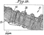
図1Aおよび1Bは弛緩された状態および破断後の弛緩された状態のそれぞれで、「S」方向にメーター当り500回(以下tpmと記す)撚られた1本の22/7dtex/7フィラメント フラット ナイロン ヤーンで一重被覆されたLycra(登録商標)ヤーン タイプT-162Cに平行な100%ステンレス スチールの走査型電子顕微鏡(SEM)図を示す。 Figures 1A and 1B show a single 22 / 7dtex / 7 filament flat nylon twisted 500 times per meter (hereinafter referred to as tpm) in the "S" direction in a relaxed state and a relaxed state after breaking, respectively. FIG. 4 shows a scanning electron microscope (SEM) view of 100% stainless steel parallel to a single-layer yarn-coated Lycra® yarn type T-162C.
図2は「S」方向に300tpmおよび「Z」方向に200tpm撚られた1本の22/7dtex/7フィラメント フラット ナイロン ヤーンで二重被覆されたLycra(登録商標)ヤーン タイプT-162Cに平行な100%ステンレス スチールの走査型電子顕微鏡図を示す。 Figure 2 is parallel to a Lycra® yarn type T-162C double coated with one 22 / 7dtex / 7 filament flat nylon yarn twisted at 300 tpm in the “S” direction and 200 tpm in the “Z” direction. A scanning electron micrograph of 100% stainless steel is shown.
図3Aおよび3Bは弛緩された状態で「S」および「Z」の両方向に500tpm撚られた1本のナイロン44dtex/20フィラメント テキスチャード ナイロン ヤーンで二重被覆されたLycra(登録商標)ヤーン タイプT-162Cに平行な100%ステンレス スチールの走査型電子顕微鏡図を示す。 3A and 3B show Lycra® yarn type T, double coated with a single nylon 44dtex / 20 filament textured nylon yarn twisted at 500 tpm in both the “S” and “Z” directions. A scanning electron micrograph of 100% stainless steel parallel to -162C is shown.
図4は「S」方向に400tpm撚られた1本の弾性化されたLycra(登録商標)ヤーン タイプT-902C(200dtex、5.2倍のドラフト)で一重被覆されたLycra(登録商標)ヤーン タイプT-162Cに平行な100%ステンレス スチールの走査型電子顕微鏡図を示す。 Figure 4 shows Lycra® yarn type T single coated with one elasticized Lycra® yarn type T-902C (200 dtex, 5.2x draft) twisted 400 tpm in the `` S '' direction. A scanning electron micrograph of 100% stainless steel parallel to -162C is shown.
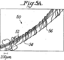
図5Aおよび5Bは伸長されたおよび弛緩された状態のそれぞれで、「S」方向に333tpm撚られた1本の22dtex/7フィラメント フラット ナイロン ヤーンで一重被覆されたLycra(登録商標)ヤーン タイプT-162Cに平行なRaytela(登録商標)プラスチック光学ファイバーの走査型電子顕微鏡(SEM)を示す。 FIGS. 5A and 5B show the Lycra® yarn type T-, which is single-coated with a single 22 dtex / 7 filament flat nylon yarn, 333 tpm twisted in the “S” direction, respectively, in the stretched and relaxed state. 1 shows a Scanning Electron Microscope (SEM) of Raytela® plastic optical fiber parallel to 162C.
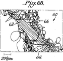
図6Aおよび6Bは弛緩された状態で、「S」方向に100tpm撚られた1本の44dtex/20フィラメント ナイロン ヤーンで一重被覆されたLycra(登録商標)ヤーン タイプT-162Cに平行なRaytela(登録商標)プラスチック光学ファイバーの走査型電子顕微鏡(SEM)を示す。 6A and 6B are in a relaxed state, Raytela (registered) parallel to Lycra® yarn type T-162C, single coated with a single 44dtex / 20 filament nylon yarn twisted 100 tpm in the `` S '' direction. 1 shows a scanning electron microscope (SEM) of a plastic optical fiber.
図7は「S」方向に400tpm撚られた1本の弾性化されたLycra(登録商標)ヤーン タイプT-902C(200dtex、5.2倍のドラフト)で一重被覆されたLycra(登録商標)ヤーン タイプT-162Cに平行なRaytela(登録商標)プラスチック光学ファイバーの走査型電子顕微鏡(SEM)を示す。 Figure 7 shows Lycra® yarn type T single coated with one elasticized Lycra® yarn type T-902C (200 dtex, 5.2x draft) twisted 400 tpm in the “S” direction. Fig. 2 shows a scanning electron microscope (SEM) of Raytela (R) plastic optical fiber parallel to -162C.
図8は種々の高係数機能性ファイバーおよび従来のテキスタイル ファイバーのための係数限定を示す応力-歪みの機械的特性データを示す。 FIG. 8 shows the stress-strain mechanical property data showing the modulus limitation for various high modulus functional fibers and conventional textile fibers.
図9は「S」方向に400tpmで撚られた弾性化されたLycra(登録商標)ヤーン タイプT-902C(200dtex、5.2倍のドラフト)で一重被覆されたLycra(登録商標)ヤーン タイプT-162Cに平行なRaytela(登録商標)プラスチック オプティカル ファイバーを含む弾性ファイバー オプティカル ヤーンが緯糸方向に導入され、向けられた経糸は非弾性コットン
ヤーンによって構成された、ジャカード織機タイプT.I.S.TMF100で製造された織られたファブリックの弛緩された状態における走査型電子顕微鏡(SEM)図を示す。
Figure 9 shows Lycra® yarn type T-162C single coated with elasticized Lycra® yarn type T-902C (200dtex, 5.2x draft) twisted at 400 tpm in the `` S '' direction. Jacquard loom type TIS, in which an elastic fiber optical yarn including Raytela® plastic optical fiber parallel to the fiber is introduced in the weft direction and the directed warp is constituted by an inelastic cotton yarn. FIG. 2 shows a scanning electron microscope (SEM) view of a woven fabric made with TMF100 in a relaxed state.
図10Aおよび10Bは弛緩された状態および伸長された状態でそれぞれ約1分間ホフマン(Hoffmann)HR2Aスチーム プレス テーブルの元で蒸発作用を受けた図9に示された織られたファブリックの走査型電子顕微鏡(SEM)図を示す。 FIGS. 10A and 10B are scanning electron microscopes of the woven fabric shown in FIG. 9 subjected to evaporation under a Hoffmann HR2A steam press table in a relaxed and stretched state for about 1 minute, respectively. (SEM) shows the figure.
図11Aおよび11Bは約180℃に約2分間マシス(Mathis)ラボラトリー ヒート ステンタを介したヒートセットをさらに受けた、図10Aおよび10Bに示された織られたファブリックの弛緩された状態における異なる倍率での走査型電子顕微鏡(SEM)図を示す。 FIGS. 11A and 11B are further subjected to heat set through a Mathis laboratory heat stenter at about 180 ° C. for about 2 minutes at different magnifications in the relaxed state of the woven fabric shown in FIGS. 10A and 10B. The scanning electron microscope (SEM) figure of is shown.
図12は本発明による弾性複合ヤーンの概略図である。 FIG. 12 is a schematic view of an elastic composite yarn according to the present invention.
発明の詳細な説明
本発明に従って高係数または低屈曲ファイバーまたはヤーンを含む弾性複合ヤーンを製造できることを見出した。本発明の範囲内にある弾性複合ヤーンは(a)弾性芯部材(または「弾性芯」)および(b)非弾性機能性芯部材からなる複合芯を含み、複合芯は少なくとも1つの複合被覆によって取り囲まれている。
Detailed Description of the Invention It has been found that elastic composite yarns comprising high modulus or low bending fibers or yarns can be produced according to the present invention. Elastic composite yarns within the scope of the present invention include a composite core consisting of (a) an elastic core member (or “elastic core”) and (b) an inelastic functional core member, the composite core comprising at least one composite coating. Surrounded.
弾性芯部材は予め決められた弛緩された単位長さが(L)であって、予め決められた(N×L)の引っ張られた長さを有し、Nは弾性部材に印加されたドラフトを表す、好ましくは約1.0から約8.0の範囲の数である。非弾性機能性芯部材は(N×L)の一定の長さを有する。 The elastic core member has a predetermined relaxed unit length (L) and has a predetermined (N × L) pulled length, and N is a draft applied to the elastic member. And preferably a number in the range of about 1.0 to about 8.0. The inelastic functional core member has a certain length of (N × L).
本発明の範囲内にある弾性複合ヤーンはさらに少なくとも1つの複合被覆を含む。複合被覆は(i)少なくとも1つの弾性被覆部材、および(ii)弾性被覆部材を取り囲む少なくとも1つの非弾性被覆部材を含む。複合被覆は、複合ヤーンにかけられた伸び応力のすべてが実質的に弾性芯部材および弾性被覆部材によって支えられるように、弾性芯部材の引っ張られた長さと等しいかより長い弛緩された長さを有する。 Elastic composite yarns within the scope of the present invention further comprise at least one composite coating. The composite coating includes (i) at least one elastic covering member, and (ii) at least one inelastic covering member surrounding the elastic covering member. The composite coating has a relaxed length that is equal to or longer than the stretched length of the elastic core member such that all of the elongation stress applied to the composite yarn is substantially supported by the elastic core member and the elastic coating member. .
弾性芯部材
弾性芯部材は、商標LYCRA(登録商標)の元でINVISTA North America S.a r.l.(Wilmington,Delaware,USA,19880)によって販売されるスパンデックス材料のように1つまたは複数(すなわち2またはそれ以上)の弾性ヤーンのフィラメントを用いて提供し得る。
Elastic core member Elastic core member is one or more (i.e. two or more), such as the spandex material sold by INVISTA North America Research (Wilmington, Delaware, USA, 19880) under the trademark LYCRA®. ) Elastic yarn filaments.
弾性芯部材の引っ張れらた長さ(N×L)は、弾性部材が伸長され、その弛緩された(応力無しの)単位長さLの約5%以内に復元することができる長さであると定義される。さらに一般的に弾性芯部材にかけられたドラフト(N)は、弾性芯部材および被覆を構成するポリマーの化学的および物理的特性、並びに使用されるテキスタイル プロセスに左右される。スパンデックス ヤーンから作られる弾性部材の被覆プロセスにおいて、典型的なドラフトは約1.0と約8.0の間、最も好ましくは約1.2と約5.0の間である。 The stretched length (N × L) of the elastic core member is a length that allows the elastic member to be stretched and restored within about 5% of its relaxed (no stress) unit length L. It is defined as More generally, the draft (N) applied to the elastic core member depends on the chemical and physical properties of the polymer comprising the elastic core member and the coating, and the textile process used. In the coating process of elastic members made from spandex yarns, typical drafts are between about 1.0 and about 8.0, most preferably between about 1.2 and about 5.0.
あるいは合成2成分(synthetic bicomponent)マルチフィラメント テキスタイル ヤーンはまた弾性芯部材を形成するのに使用され得る。合成2成分フィラメント コンポーネント
ポリマーは熱可塑物質であり、より好ましくは合成2成分フィラメントは溶融紡糸であり、最も好ましくはコンポーネント ポリマーはポリアミドとポリエステルからなるグループから選ばれる。
Alternatively, a synthetic bicomponent multifilament textile yarn can also be used to form an elastic core member. Synthetic bicomponent filament The component polymer is a thermoplastic, more preferably the synthetic bicomponent filament is melt spun, and most preferably the component polymer is selected from the group consisting of polyamide and polyester.
ポリアミド2成分マルチフィラメント テキスタイル ヤーンの好ましいクラスは、自己しぼ(self-crimping)であり、また「セルフ-テクスチャリング(delf-texturing)」とも呼ばれる、それらのナイロン2成分ヤーンである。これらの2成分ヤーンは、第1の相対粘度を有するナイロン66ポリマーまたはコポリアミド、および第2の相対粘度を有するナイロン66ポリマーまたはコポリアミドを含み、ポリマーまたはコポリアミドの両方は、個々のフィラメントの断面に見られるように並んだ(side-by-side)関係にある。商標TACTEL T-800TM(登録商標)の元でINVISTA North America S.a.r.l.によって販売されるヤーンのような自己しぼナイロン ヤーンは、特に有用な2成分弾性ヤーンである。
A preferred class of polyamide two-component multifilament textile yarns are those nylon two-component yarns that are self-crimping and are also referred to as “self-texturing”. These two component yarns include a
好ましいポリエステル複合ポリマーは、ポリエチレン テレフタレート(PET)、ポリトリメチレン テレフタレート(PTT)およびポリテトラブチレン テレフタレートを含む。さらに好ましいポリエステル2成分フィラメントは、PETポリマーの成分およびPTTポリマーの成分を含む。フィラメントの両成分は、個々のフィラメントの断面に見られるように並んだ関係にあり得る。この記述に合う特に有利なフィラメント ヤーンは、商標 T-400TM Next Generation
Fiberの元でINVISTA North America S.ar.l.によって販売されるヤーンである。これらの2成分ヤーンからの弾性部材のための被覆プロセスは、スパンデックスにおけるよりも少ないドラフトの利用を含む。
Preferred polyester composite polymers include polyethylene terephthalate (PET), polytrimethylene terephthalate (PTT) and polytetrabutylene terephthalate. Further preferred polyester bicomponent filaments comprise a component of a PET polymer and a component of a PTT polymer. Both components of the filament can be in side-by-side relationship as seen in the cross section of the individual filament. A particularly advantageous filament yarn that meets this description is the trademark T-400 TM Next Generation.
Yarn sold by Fiber under INVISTA North America S.ar.l. The coating process for elastic members from these two component yarns involves the use of less draft than in spandex.
一般的に、ポリアミドまたはポリエステル2成分マルチフィラメント テキスタイル ヤーンの両方のドラフトは、約1.0から約5.0の間である。 Generally, the draft of both polyamide or polyester bicomponent multifilament textile yarns is between about 1.0 and about 5.0.
機能性芯部材
「機能性芯部材」という用語は、少なくとも1つの機能を有し、あるいはテキスタイル ファイバーと一般に関連付けられる機械的特性を越えて広がる少なくとも1つの特性を示す1つまたはそれ以上のファイバーを表す。そのような部材と関連付けられる機能または特性は例えば、ファイバー オプティック データ伝達、高周波への誘電体としての利用(すなわちガラスおよび/またはシリカ ファイバーを用いるそれら)、電気的、オプティカルまたは磁界の元での活性、エネルギーの1つの形態から他の形態へエネルギーを変換する能力、およびセンサ、モニターまたはアクチュエーターとしての利用を含み得る。
Functional core member The term `` functional core member '' refers to one or more fibers that have at least one function or that exhibit at least one characteristic that extends beyond the mechanical properties commonly associated with textile fibers. To express. Functions or properties associated with such components include, for example, fiber optic data transmission, utilization as dielectrics for high frequencies (i.e. those using glass and / or silica fibers), activity under electrical, optical or magnetic fields. , The ability to convert energy from one form of energy to another, and use as a sensor, monitor or actuator.
機能性芯部材は例えば、ステンレス スチール ファイバー、ステンレス スチール ヤーン、導電性金属被覆アラミド ファイバー、プラスチック オプティカル ファイバー(POF)、およびシリカまたはガラス オプティカル ファイバーを含む低屈曲係数ファイバーの群から選択し得る。非弾性機能性芯部材は例えば、20%より小さい伸び制限における2Nより大きい破断力または20%より小さい伸び制限における2Nより大きい降伏点を有する。 The functional core member may be selected, for example, from the group of stainless steel fibers, stainless steel yarns, conductive metal-coated aramid fibers, plastic optical fibers (POF), and low bend modulus fibers including silica or glass optical fibers. Inelastic functional core members have, for example, a breaking force greater than 2N at an elongation limit of less than 20% or a yield point greater than 2N at an elongation limit of less than 20%.
機能性芯部材はさらに、電歪ポリマー、電歪エラストマー、強誘電性ファイバー、磁歪ポリマーもしくはファイバー複合物、光子ファイバーおよびナノ複合ファイバー、熱応答性(例えばポリマーまたは金属合金の形状記憶ワイヤー)、蛍光性およびエレクトロクロミック ファイバー、およびファイバーを含む感光性液晶の、ポリマー(例えばポリアミド9、ポリアミド11)からのまたはセラミック ファイバー複合物からの圧電ファイバーを含み得る。 Functional core members are also electrostrictive polymers, electrostrictive elastomers, ferroelectric fibers, magnetostrictive polymers or fiber composites, photonic fibers and nanocomposite fibers, thermal responsiveness (eg polymer or metal alloy shape memory wires), fluorescent And electrochromic fibers, and photosensitive liquid crystal containing fibers, piezoelectric fibers from polymers (eg polyamide 9, polyamide 11) or from ceramic fiber composites.
その最も基礎的な形態において、機能性芯部材は1つまたは複数(すなわち2またはそれ以上)の機能性ファイバーの撚り(strand)を含む。 In its most basic form, the functional core member includes one or more (ie, two or more) functional fiber strands.
代わりの形態では、機能性芯部材はその上に1つまたはそれ以上の機能性ファイバーを有する合成ポリマー ヤーンを含む。適した合成ポリマー ヤーンは、コンティニュアス フィラメント ナイロン ヤーン(例えば一般にN66、N6、N610、N612、N7、N9と称される合成ナイロン ポリマーから)、コンティニュアス フィラメント ポリエステル ヤーン(例えば一般にPET、3GT、4GT、2GN、3GN、4GNと称される構成ポリエステル ポリマーから)、ステープル ナイロン ヤーン、またはステープル ポリエステル ヤーンの間から選ばれる。そのような複合機能性ヤーンは、撚り合わされ(plied)、紡糸され、あるいはテキスチャーされたヤーンのような複合ヤーンを生成するために従来のヤーン紡糸技術によって形成され得る。 In an alternative form, the functional core member comprises a synthetic polymer yarn having one or more functional fibers thereon. Suitable synthetic polymer yarns are continuous filament nylon yarns (e.g. from synthetic nylon polymers commonly referred to as N66, N6, N610, N612, N7, N9), continuous filament polyester yarns (e.g. generally PET, 3GT, 4GT, 2GN, 3GN, from constituent polyester polymers called 4GN), staple nylon yarn, or staple polyester yarn. Such composite functional yarns can be formed by conventional yarn spinning techniques to produce composite yarns such as plied, spun, or textured yarns.
複合被覆
本発明の複合被覆は、弾性被覆部材の回りのまたはそれを取り囲む弾性被覆部材および非弾性被覆部材を含む。複合被覆の長さは、弾性芯部材の引っ張られた長さ(N×L)より長いか等しくあるべきである。
Composite Coating The composite coating of the present invention includes an elastic coating member and a non-elastic coating member around or surrounding the elastic coating member. The length of the composite coating should be longer than or equal to the stretched length (N × L) of the elastic core member.
弾性被覆部材は、弾性芯部材のために使用し得るいかなる材料からも構成し得る。 The elastic covering member may be composed of any material that can be used for the elastic core member.
非弾性被覆部材は、非導電性非弾性合成ポリマー ファイバーから、またはコットン、ウール、シルクおよびリンネルのような天然テキスタイル ファイバーから選択し得る。これらの合成ポリマー ファイバーは、マルチフィラメント フラット ヤーン、部分的に配向されたヤーン、テクスチャード ヤーンから選ばれたコンティニュアス フィラメントまたはステープル ヤーン、ナイロン、ポリエステルもしくは混合フィラメント ヤーンから選ばれた2成分ヤーンであり得る。 The non-elastic covering member may be selected from non-conductive non-elastic synthetic polymer fibers or from natural textile fibers such as cotton, wool, silk and linen. These synthetic polymer fibers are multicomponent flat yarns, partially oriented yarns, continuous filaments selected from textured yarns or bicomponent yarns selected from staple yarns, nylon, polyester or mixed filament yarns. possible.
任意に、非弾性被覆部材は4Nより小さい引っ張り強度または4Nより小さい降伏点を有する機能性ヤーンであり得る。そのような機能性ヤーンは金属ワイヤーのような電気的またはオプティカル特性を有するヤーンを含み得る。 Optionally, the inelastic covering member can be a functional yarn having a tensile strength less than 4N or a yield point less than 4N. Such functional yarns can include yarns having electrical or optical properties such as metal wires.
非弾性被覆部材は好ましくはナイロンである。ナイロン6、ナイロン66、ナイロン46、ナイロン7、ナイロン9、ナイロン10、ナイロン11、ナイロン610、ナイロン612、ナイロン12、および混合物並びにそれらのコポリアミドのような合成ポリアミド成分ポリマーからなるナイロン ヤーンが好ましい。コポリアミドの場合、それぞれ商標DYTEK A(登録商標)およびDYTEK EP(登録商標)の元でINVISTA North America S.a r.l.(Wilmington,Delaware,USA,19880)から入手可能なジアミンのグループから脂肪族ジアミン成分が選ばれる、40モルパーセントに至るまでのポリアジパミドを有するナイロン66を含むものが特に好ましい。
The inelastic covering member is preferably nylon. Nylon yarns composed of synthetic polyamide component polymers such as nylon 6,
ナイロンから非弾性被覆部材を作ることは、テキスタイル ナイロン ヤーンおよび伝統的なナイロン被覆スパンデックス ヤーンの着色のための従来の染料およびプロセスを用いて複合ヤーンを染色可能にする。 Making an inelastic coated member from nylon makes it possible to dye composite yarns using conventional dyes and processes for the coloring of textile nylon yarns and traditional nylon-coated spandex yarns.
もし非弾性被覆部材がポリエステルなら、好ましいポリエステルは、ポリエチレン テレフタレート(PETとしても知られる2GT)、ポリトリメチレン テレフタレート(PTTとしても知られる3GT)あるいはポリテトラブチレン テレフタレート(4GT)のいずれかである。ポリエステル マルチフィラメント ヤーンから非弾性被覆部材を作ることはまた、従来のテキスタイル プロセスにおける染色と取り扱いを容易にする。 If the inelastic covering is polyester, the preferred polyester is either polyethylene terephthalate (2GT, also known as PET), polytrimethylene terephthalate (3GT, also known as PTT), or polytetrabutylene terephthalate (4GT). Making an inelastic covering from a polyester multifilament yarn also facilitates dyeing and handling in conventional textile processes.
機能性芯部材および複合被覆の相対量は、実質的にその伸長されない(すなわち、拡張によって変形されない)長さに伸び戻る弾性芯部材の能力により、また機能性芯部材の機能性特性により選ばれる。この文書で用いられるように「変形されない(undeformed)」は、弾性芯部材がその弛緩された(応力無しの)単位長さLの約プラスマイナス5%以内に復元することを意味する。 The relative amounts of the functional core member and the composite coating are selected by the ability of the elastic core member to stretch to a length that is substantially unstretched (ie not deformed by expansion) and by the functional properties of the functional core member. . “Undeformed” as used in this document means that the elastic core member recovers within about plus or minus 5% of its relaxed (no stress) unit length L.
複合被覆に有用な材料を有する機能性フィラメントとして有用な弾性フィラメントおよび材料の一重被覆(single covering)、二重被覆(double
covering)、エア ジェット被覆、からませ、撚り合わせ、巻き付けのためのいかなる伝統的なテキスタイル プロセスも、本発明による機能性弾性複合ヤーンを作るのに適することがわかった。
Elastic filaments and materials useful as functional filaments with materials useful for composite coating, single covering, double covering
It has been found that any traditional textile process for covering), air jet covering, entanglement, twisting and winding is suitable for making a functional elastic composite yarn according to the present invention.
ほとんどの場合、複合芯が複合被覆によって取り囲まれまたは被覆される状態は弾性複合ヤーンを得るために重要ではない。この構造のこれらの機能性弾性複合ヤーンの望ましい特性はそれらの応力-歪みのふるまいである。例えば印加された伸び力の応力の元で、多重巻き付け(一般的に1回(一重巻き付け)から約10,000回)で複合芯の回りに配置された複合被覆は、外部の応力による歪み無しで自由に伸びることができる。 In most cases, the condition in which the composite core is surrounded or covered by the composite coating is not critical for obtaining an elastic composite yarn. A desirable property of these functional elastic composite yarns of this structure is their stress-strain behavior. For example, a composite coating placed around a composite core in multiple windings (generally from one (single winding) to about 10,000) under the stress of the applied elongation force is free without distortion due to external stress. Can stretch.
もし複合ヤーンが弾性芯部材の破断伸び近くまで伸長されるなら、複合被覆は負荷の一部を受け、弾性芯部材および機能性芯部材を効果的に保護し、それらが破断するのを防ぐのに役立つ。「負荷の一部(portion of the load)」の用語はここでは、負荷の約1から約99%、より好ましくは負荷の10%から80%、最も好ましくは負荷の25%から50%のいかなる量を意味するために用いられている。 If the composite yarn is stretched to near the breaking extension of the elastic core member, the composite coating will receive part of the load, effectively protecting the elastic core member and the functional core member and preventing them from breaking. To help. The term “portion of the load” is used herein to refer to anything from about 1 to about 99% of the load, more preferably 10% to 80% of the load, most preferably 25% to 50% of the load. Used to mean quantity.
複合芯は選択的に複合被覆によって波状に巻き付けられ得る。波状の巻き付けは図12に概略的に表され、弾性部材40例えばLYCRA(登録商標)ヤーンは、非弾性被覆部材10例えばナイロンで、巻き付けが波状周期(P)によって特徴付けられるやり方で巻き付けられる。
The composite core can optionally be wound into a wave by a composite coating. The wavy wrap is schematically represented in FIG. 12, where the
本発明の具体的な実施例および手順がいま実施例によって以下のようにさらに記述されるだろう。 Specific embodiments and procedures of the invention will now be further described by way of example as follows.
テスト方法
ファイバーとヤーンの応力-歪み特性の計測
ファイバーとヤーンの応力-歪み特性は破断点への時間的一定割合の伸びでダイナモメーターを使用して決定された。Instron Corp,100 Royall Street,Canton,Massachusetts,02021 USAによって製造されたダイナモメーターが使用された。
Test methods Measurement of stress-strain properties of fibers and yarns Stress-strain properties of fibers and yarns were determined using a dynamometer at a constant rate of elongation to break. A dynamometer manufactured by Instron Corp, 100 Royall Street, Canton, Massachusetts, 02021 USA was used.
標本の状態は約22℃プラスマイナス約1℃、相対湿度約60%プラスマイナス約5%であった。テストは5cmのゲージ長さでクロスヘッド速度は約50cm/minでなされた。約20cmの長さの糸がボビンから除かれ、空調された実験室内で少なくとも16時間ビロード板の上で弛緩される。このヤーンの標本は、張力または弛みのいずれかを与えないようにヤーンdtexに対応する予備引っ張り荷重がかけられてジョーズ(jaws)内に置かれる。 The condition of the specimen was about 22 ° C plus or minus about 1 ° C and relative humidity about 60% plus or minus about 5%. The test was conducted at a gauge length of 5 cm and a crosshead speed of about 50 cm / min. A thread about 20 cm long is removed from the bobbin and allowed to relax on the velvet plate for at least 16 hours in an air conditioned laboratory. The yarn specimen is placed in the jaws with a pre-tension load corresponding to the yarn dtex so as not to impart either tension or slack.
ファブリックの伸長の計測
伸長の織られたファブリックの伸長および復元は、一定の速度の引っ張りテストを実行するために万能電気-機械テストおよびデータ獲得システムを用いて決定された。該システムはInstron Corp,100 Royall Street,Canton,Massachusetts,02021 USAからのものが用いられた。
Fabric Stretch Measurement Stretch woven fabric stretch and restitution was determined using a universal electro-mechanical test and data acquisition system to perform a constant speed tensile test. The system was from Instron Corp, 100 Royall Street, Canton, Massachusetts, 02021 USA.
2つのファブリック特性(1)ファブリックの伸長および(2)ファブリックの拡張(変形)がこの器械を用いて計測された。実現できるファブリックの伸長は、0から約30ニュートンの間の特定の負荷によって引き起こされる伸びの総計として計測され、また分当り約300mmの割合で伸長されたとき、その元のファブリック標本の長さにおけるパーセンテージ変化として表された。ファブリックの拡張は、約30分間実現できるファブリック伸長の約80%で保持され、その後約60分間弛緩された、ファブリック標本の復元されない長さとして計測された。実現できるファブリック伸長の80%が、ファブリックの伸びの約35%よりも大きかった場合には、このテストは約35%の伸びに制限された。それからファブリックの拡張は元の長さのパーセンテージとして表された。 Two fabric properties (1) fabric stretch and (2) fabric expansion (deformation) were measured using this instrument. Achievable fabric stretch is measured as the total stretch caused by a specific load between 0 and about 30 Newtons, and when stretched at a rate of about 300 mm per minute, at the length of the original fabric specimen Expressed as a percentage change. Fabric expansion was measured as the irreversible length of the fabric specimen that was held at about 80% of the fabric stretch that could be achieved for about 30 minutes and then relaxed for about 60 minutes. The test was limited to about 35% elongation when 80% of the fabric elongation that could be achieved was greater than about 35% of the fabric elongation. Then the fabric expansion was expressed as a percentage of the original length.
伸長方向における伸長の織られたファブリックの伸びまたは最大伸長は3サイクル テスト手順を用いて決定された。計測された最大伸びは、約30ニュートンの負荷で第3のテスト サイクルにおいて見られた初期の見本長さに対するテスト標本の最大拡張の割合だった。この第3のサイクル値はファブリック標本の手による伸びに相当する。このテストは、この3サイクルテストのために特に準備した上述の万能電気-機械テストおよびデータ獲得システムを用いてなされた。 The stretch or maximum stretch of the stretch woven fabric in the stretch direction was determined using a three cycle test procedure. The maximum elongation measured was the ratio of the maximum extension of the test specimen to the initial sample length seen in the third test cycle at a load of about 30 Newtons. This third cycle value corresponds to the elongation of the fabric specimen by hand. This test was performed using the above-described universal electro-mechanical test and data acquisition system specifically prepared for this three-cycle test.
実施例の説明に出てくる参照番号は、添付の図面内で用いられた参照番号を引用する。 Reference numerals appearing in the description of the embodiments refer to the reference numerals used in the accompanying drawings.
比較実施例1
156decitex(dtex)Lycra(登録商標)ヤーン タイプT-162Cは、その弛緩された長さの3.8倍で引っ張られ、ヤーン被覆I.C.B.T.マシーン モデルG307を介して100%ステンレス スチール ヤーンに平行に供給された。100%ステンレス スチール ヤーンは、スレッド(thread)当り275フィラメントおよびSprint Metal(フランス)から入手された12のフィラメント サイズを有する2つの撚り合わされたスレッドからなるエンドレスのマルチフィラメント ヤーン グレード316Lであった。(Lycra(登録商標)およびステンレス スチール ヤーンからなる)この芯複合ヤーンは、「S」方向に500tpm(引っ張られたLycra(登録商標)のメーター当りの回数)で撚り合わされた22dtex/7フィラメント フラット ナイロン ヤーンで一重被覆された。ナイロン ヤーン16で被覆されたLycra(登録商標)ヤーン12およびステンレス スチール ヤーン14を有する、このヤーン構造10は図1Aに示される。ヤーン10が伸長されるとき、ナイロンは弾力性を持たせることができず、図1Bに示されるようにそれは破断する。
Comparative Example 1
156decitex (dtex) Lycra® yarn type T-162C was pulled at 3.8 times its relaxed length and fed in parallel to a 100% stainless steel yarn via a yarn coated ICBT machine model G307. The 100% stainless steel yarn was an endless multifilament yarn grade 316L consisting of two twisted threads with 275 filaments per thread and 12 filament sizes obtained from Sprint Metal (France). This core composite yarn (consisting of Lycra® and stainless steel yarn) is 22dtex / 7 filament flat nylon twisted at 500 tpm (number of times per meter of pulled Lycra®) in the “S” direction Single coated with yarn. This
比較実施例2
比較実施例1におけるようにLycra(登録商標)およびステンレス スチール ヤーンの芯複合ヤーンは、「S」方向に300tpm(引っ張られたLycra(登録商標)のメーター当りの回数)および「Z」方向に200tpmで撚り合わされた22dtex/7フィラメント フラット ナイロン ヤーンで二重被覆された。ナイロン16で被覆されたLycra(登録商標)ヤーン12およびステンレス スチール ヤーン14を有する、このヤーン構造20は図2に示される。ヤーン20が伸長されるとき、本発明の比較実施例1に比較してより高い度合いで被覆されたという事実にかかわらず、ナイロンは弾力性を持たせることができず、それは破断する。
Comparative Example 2
As in Comparative Example 1, the core composite yarn of Lycra® and stainless steel yarn was 300 tpm in the “S” direction (number of times the Lycra® was pulled per meter) and 200 tpm in the “Z” direction. Double coated with 22dtex / 7 filament flat nylon yarn twisted together. This
比較実施例3
被覆されたヤーンは、「S」および「Z」の両方向に500tpmで撚り合わされたことを除き、比較実施例2におけるように生成された。ヤーンが伸長されたとき、ナイロンは弾力性を持たせることができず、それは破断する。
Comparative Example 3
The coated yarn was produced as in Comparative Example 2, except that it was twisted at 500 tpm in both the “S” and “Z” directions. When the yarn is stretched, the nylon cannot be made elastic and it breaks.
比較実施例4
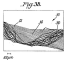
被覆されたヤーンは、用いられたナイロン ヤーンが44dtex/20フィラメント テクスチャード ヤーンであったことを除き、比較実施例3におけるように生成された。このヤーン30の構造は図3Aおよび3Bに示される。比較実施例3に比較してより強いナイロン ヤーン36が用いられたけれども、ヤーン30が伸長されたとき、ナイロンは弾力性を持たせることができず、それは破断する。
Comparative Example 4
The coated yarn was produced as in Comparative Example 3 except that the nylon yarn used was a 44 dtex / 20 filament textured yarn. The structure of this
実施例1
被覆されたヤーンは、芯複合ヤーンが、「S」方向に400tpmで撚り合わされた弾性化されたヤーンで一重被覆されたことを除き、比較実施例1-4と類似の方法で生成された。弾性化されたヤーンは、二重被覆されたLycra(登録商標)ヤーン(タイプT-902C、200dtex、5.2倍のドラフト)であった。このヤーン40の構造は、弾性化されたヤーン46によって被覆されたLycra(登録商標)ヤーン42およびステンレス スチール ヤーン44と共に図4に示される。図4に示されるようにこのヤーン40は、弛緩された状態で直線状のセグメントからなる構造を示し、被覆されたヤーンは、伸長された状態でステンレス スチールのループの芯複合ヤーンを保つ。ヤーン40が伸長されるとき、ステンレス スチール ヤーンのループはLycra(登録商標)芯と平行に伸長する傾向があり、伸長の間、無傷を維持する完全に伸長されたヤーンを提供する。このヤーンはさらに通例のテキスタイル プロセスによって処理し得る。
Example 1
The coated yarn was produced in a manner similar to Comparative Examples 1-4, except that the core composite yarn was single coated with an elasticized yarn twisted at 400 tpm in the “S” direction. The elasticized yarn was a double-coated Lycra® yarn (type T-902C, 200 dtex, 5.2x draft). The structure of this
比較実施例5
156decitex(dtex)Lycra(登録商標)ヤーン タイプT-162Cは、その弛緩された長さの3.8倍に引っ張られ、ヤーン被覆I.C.B.T.マシーン モデルG307を介してプラスチック オプティカル ファイバーに平行に供給された。プラスチック オプティカル ファイバーは、フッ素化されたポリマー クラッドおよびポリメチル メタクリレート芯から構成されたTorayの610dtexからのタイプRaytela(登録商標)であった。この芯複合ヤーンは、「S」方向に333tpm(引っ張られたLycra(登録商標)のメーター当りの回数)で撚り合わされた22dtex/7フィラメント フラット ナイロン ヤーンで一重被覆された。このヤーン構造50は、ナイロン ヤーン56で被覆されたLycra(登録商標)ヤーン52およびプラスチック オプティカル ファイバー54と共に図5Bに示される。この構造50は、図5Bに示されるように、弛緩の間、直径で数cmに至るまでのオプティカル ファイバー54の大きなループを生成する。ヤーン50が伸長されるとき、図5Aに示されるようにナイロンは弾力性を持たせることができず、それは破断する。
Comparative Example 5
156decitex (dtex) Lycra® yarn type T-162C was pulled 3.8 times its relaxed length and fed in parallel to the plastic optical fiber via a yarn coated ICBT machine model G307. The plastic optical fiber was of type Raytela® from Toray's 610 dtex composed of a fluorinated polymer cladding and a polymethylmethacrylate core. This core composite yarn was single coated with a 22 dtex / 7 filament flat nylon yarn twisted in the “S” direction at 333 tpm (number of meters per meter of Lycra® pulled). This
比較実施例6
被覆されたヤーンは、「S」方向に100tpmで撚り合わされたより強いナイロン ヤーン(44dtex/20フィラメント)で一重被覆されたことを除き、比較実施例5により作られた。このヤーン60の構造は、ナイロン66で被覆されたLycra(登録商標)ヤーン62およびプラスチック オプティカル ファイバー64と共に図6Aおよび6Bに示される。ヤーン60は示されるように直線状の部分とヤーンが弛緩している間に形成されたオプティカル ファイバーのループからなる。これらのループはこのヤーンのさらなる処理を妨げるように数cmの直径くらい大きくし得る。ヤーンが伸長されるとき、ナイロン ヤーンは破断する。
Comparative Example 6
The coated yarn was made according to Comparative Example 5 except that it was single coated with a stronger nylon yarn (44 dtex / 20 filament) twisted at 100 tpm in the “S” direction. The structure of this
実施例2
ポリマー オプティカル ファイバーに基づく被覆されたヤーンは、(Lycra(登録商標)およびオプティカル ファイバーからなる)複合芯ヤーンが、「S」方向に400tpmで撚り合わされた弾性化されたヤーンで一重被覆されたことを除き、比較実施例5と6におけるように形成された。弾性化されたヤーンはLycra(登録商標)ヤーン(タイプT-902C、200dtex、5.2倍のドラフト)で二重被覆された。このヤーン70の構造は、ナイロン76で被覆されたLycra(登録商標)ヤーン72およびプラスチック オプティカル ファイバー74と共に、図7に示される。このヤーンはオプティカル ファイバーの直線状の部分と小さなループから構成される。ヤーンが伸長するとき、オプティカル ファイバーのループは複合ヤーンの破断無しにまっすぐになり、テキスタイル プロセスによって処理され得るヤーンを提供する。
Example 2
A coated yarn based on polymer optical fiber is a composite core yarn (consisting of Lycra® and optical fiber) that is single-coated with an elasticized yarn twisted at 400 tpm in the “S” direction. Except as described in Comparative Examples 5 and 6. The elasticized yarn was double coated with Lycra® yarn (type T-902C, 200 dtex, 5.2x draft). The structure of this
実施例3
織られたファブリック90はジャカード製織織機タイプT.I.S. TMF100で生成された。実施例2の弾性ファイバー オプテック ヤーンは、ファブリック構造の緯糸方向に導入された。経糸方向は非弾性コットン ヤーン98のみで構成された。作られたファブリック構造は、オプティックのファイバーと交差する経糸との間に最大限の空間を与えるためにサテン16だった。このように導入されたオプティカル ファイバーは、図9に示されるようにファブリックの外側に伸びるプラスチック オプティカル ファイバーのループを形成する。この場合、ファブリックは伸長が制限され、ファブリックが伸長されるときループはいささか短くなるが、完全には拡張しない。
Example 3
The woven
実施例4
実施例3のファブリックはHoffmann HR2Aスチーム プレス テーブルの元で1分間蒸発作用を受けた。織られたファブリックは、弾性ファイバー オプティック ヤーンの作用により引き起こされるように実質的に縮んだ。この状態で、ファブリック100は実質的な伸長および復元機能を発現させた。弛緩された状態では、これは図10Aに示されるように実施例3で観察された特徴に比較してファイバー オプティック94ループの寸法が増加する結果となる。伸長された状態では、図10Bに示されるようにループは完全に平らにされ、完全に平らな表面となる。このようにファブリックの伸長および復元を制御することによって、テキスタイル構造内でのファイバー オプティック ループ曲がりの大小の制御が存在する。
Example 4
The fabric of Example 3 was evaporated for 1 minute under a Hoffmann HR2A steam press table. The woven fabric was substantially shrunk as caused by the action of the elastic fiber optic yarn. In this state, the
実施例5
実施例4のファブリックはMathis laboratory heat stenterを介して約180℃約2分間加熱調整を受けられた。ファブリック110が完全に固くなり、平らなファブリック表面を生成するようにファイバー オプティック94ループが完全に平らになったことが図11AとBで観察された。このようにファブリックの選択部分の加熱を制御することによって、ファイバー オプティック ループをまっすぐにすることを強要すること、およびそれゆえファイバー オプティックのループまたは直線状の要素を含み得るファブリック領域の制御が可能である。これは製織構造によって誘導される制御に比較して追加的な自由の程度を導入可能である。
Example 5
The fabric of Example 4 was heat adjusted through a Mathis laboratory heat stenter at about 180 ° C. for about 2 minutes. It was observed in FIGS. 11A and B that the
上記実施例は例証だけの目的のためである。添付の特許請求の範囲内にある多数の他の実施例が技術者にとって明らかであろう。 The above examples are for illustrative purposes only. Many other embodiments within the scope of the appended claims will be apparent to those skilled in the art.
Claims (18)
前記複合芯は、
(a)弛緩された単位長さがLであって、
Nが1.0から8.0の範囲にある(N×L)の引っ張られた長さを有する弾性芯部材、
(b)(N×L)の一定の長さを有する非弾性芯部材
を含み、
前記複合被覆は、
(a)少なくとも1つの弾性被覆部材と
(b)前記弾性被覆部材を取り囲む少なくとも1つの非弾性被覆部材
を含み、
前記複合被覆は、
前記弾性芯部材の引っ張られた長さ(N×L)より長い弛緩された長さを有し、
当該弾性複合ヤーンに印加された伸び応力の実質的にすべてが前記弾性芯部材と前記弾性被覆部材によって支えられる弾性複合ヤーン。Including a composite core and a composite coating;
The composite core is
(a) The relaxed unit length is L,
An elastic core member having a stretched length of (N × L) where N is in the range of 1.0 to 8.0;
(b) an inelastic core member having a constant length of (N × L),
The composite coating is
(a) at least one elastic covering member;
(b) including at least one inelastic covering member surrounding the elastic covering member;
The composite coating is
The elastic core member has a relaxed length longer than the pulled length (N × L),
An elastic composite yarn in which substantially all of the elongation stress applied to the elastic composite yarn is supported by the elastic core member and the elastic covering member.
前記複合芯は、
(a)弛緩された単位長さがLであって、
Nが1.0から8.0の範囲にある(N×L)の引っ張られた長さを有する第1の弾性芯部材、
(b)N×Lの一定の長さを有する非弾性芯部材
を含み、
前記複合被覆は、
(a)第2の弾性被覆部材と
(b)少なくとも1つの非弾性部材
を含み、
(2)前記第1の弾性芯部材を(N×L)の引っ張られた長さまで引っ張り、
(3)引っ張られた長さの前記第1の弾性芯部材に実質的に平行にかつ接触して前記非弾性芯部材を置き、
(4)引っ張られた前記第1の弾性芯部材と前記非弾性芯部材の回りに前記複合被覆を複数回巻き付け、撚り合わせ、エア ジェット被覆し、または芯紡糸する弾性複合ヤーンの形成方法。(1) Prepare a composite core and composite coating,
The composite core is
(a) The relaxed unit length is L,
A first elastic core member having a pulled length of (N × L) where N is in the range of 1.0 to 8.0;
(b) an inelastic core member having a constant length of N × L,
The composite coating is
(a) a second elastic covering member;
(b) includes at least one inelastic member;
(2) Pull the first elastic core member to the stretched length of (N × L),
(3) to said first elastic core member pulled length substantially parallel to and in contact placing said non-elastic core member,
(4) A method of forming an elastic composite yarn in which the composite coating is wound a plurality of times around the stretched first elastic core member and the non-elastic core member , twisted, air jet coated, or core spun.
Applications Claiming Priority (3)
| Application Number | Priority Date | Filing Date | Title |
|---|---|---|---|
| US62716804P | 2004-11-15 | 2004-11-15 | |
| US60/627,168 | 2004-11-15 | ||
| PCT/IB2005/003345 WO2006051384A1 (en) | 2004-11-15 | 2005-11-08 | Elastic composite yarn, methods for making the same, and articles incorporating the same |
Publications (2)
| Publication Number | Publication Date |
|---|---|
| JP2008519915A JP2008519915A (en) | 2008-06-12 |
| JP4834672B2 true JP4834672B2 (en) | 2011-12-14 |
Family
ID=35636876
Family Applications (1)
| Application Number | Title | Priority Date | Filing Date |
|---|---|---|---|
| JP2007540737A Expired - Fee Related JP4834672B2 (en) | 2004-11-15 | 2005-11-08 | Elastic composite yarn, method of making it and article containing it |
Country Status (7)
| Country | Link |
|---|---|
| US (1) | US7765835B2 (en) |
| EP (1) | EP1815048B1 (en) |
| JP (1) | JP4834672B2 (en) |
| AT (1) | ATE444384T1 (en) |
| DE (1) | DE602005016957D1 (en) |
| TW (1) | TW200630511A (en) |
| WO (1) | WO2006051384A1 (en) |
Families Citing this family (29)
| Publication number | Priority date | Publication date | Assignee | Title |
|---|---|---|---|---|
| EP1815049A1 (en) * | 2004-11-15 | 2007-08-08 | Textronics, Inc. | Functional elastic composite yarn, methods for making the same, and articles incorporating the same |
| US8093160B2 (en) * | 2007-04-17 | 2012-01-10 | Cone Denim Llc | Core-spun elastic composite yarns having a filamentary core and ring-spun staple fiber sheath, and denim fabrics which include the same |
| KR100982533B1 (en) * | 2008-02-26 | 2010-09-16 | 한국생산기술연구원 | Digital garment using digital band and fabricating method thereof |
| US11603605B2 (en) * | 2008-10-17 | 2023-03-14 | The Lycra Company Llc | Fusible bicomponent spandex |
| ES2687071T3 (en) * | 2009-02-09 | 2018-10-23 | Dsm Ip Assets B.V. | Cut resistant fabric |
| GB0914502D0 (en) | 2009-08-19 | 2009-09-30 | Rolls Royce Plc | Electrical conductor paths |
| DE102010001197B4 (en) * | 2010-01-25 | 2019-05-29 | Draka Cable Wuppertal Gmbh | Sensor element and method for its production and use |
| JP2012087434A (en) * | 2010-10-20 | 2012-05-10 | Toyota Boshoku Corp | Heat generating yarn and woven or knitted fabric using the same |
| FR2970714B1 (en) * | 2011-01-21 | 2013-02-08 | Clarins Lab | LUMINOUS FABRIC, SKIN ILLUMINATION DEVICE, KIT AND METHOD FOR IMPLEMENTING THE SAME |
| FR2986013B1 (en) * | 2012-01-24 | 2015-02-13 | Calyf | ELASTIC HYBRID CABLE AND METHOD FOR MANUFACTURING SUCH A CABLE |
| EP2816146B1 (en) * | 2012-04-25 | 2017-07-05 | Marusho Shoten Co., Ltd. | Elastic composite twist yarn and process for producing same, and pile textile product obtained using said elastic composite twist yarn |
| EP3017107B1 (en) | 2013-07-02 | 2023-11-29 | The University of Connecticut | Electrically conductive synthetic fiber and fibrous substrate, method of making, and use thereof |
| DE102013215780A1 (en) * | 2013-08-09 | 2015-02-12 | Ibena Textilwerke Gmbh | Feel-good and / or thermal blanket |
| WO2015138298A1 (en) | 2014-03-12 | 2015-09-17 | The University Of Connecticut | Method of infusing fibrous substrate with conductive organic particles and conductive polymer; and conductive fibrous substrates prepared therefrom |
| DE102014103978A1 (en) * | 2014-03-24 | 2015-09-24 | Ditf Deutsche Institute Für Textil- Und Faserforschung Stuttgart | Sensorgarn |
| TWI530554B (en) * | 2014-05-30 | 2016-04-21 | Method for preparing light-absorbing and heat-storing masterbatch, its products and products thereof | |
| CN104073944B (en) * | 2014-06-20 | 2016-05-18 | 天津市藏原地毯有限公司 | A kind of Tibetan is the preparation method of composite yarn |
| EP3286767B1 (en) | 2015-04-23 | 2021-03-24 | The University of Connecticut | Highly conductive polymer film compositions from nanoparticle induced phase segregation of counterion templates from conducting polymers |
| WO2016172461A1 (en) | 2015-04-23 | 2016-10-27 | The University Of Connecticut | Stretchable organic metals, composition, and use |
| CN107217362A (en) * | 2017-07-26 | 2017-09-29 | 太仓市梓怡纺织有限公司 | The smooth super imitative cotton blended spinning face fabric of feel |
| WO2019148153A1 (en) * | 2018-01-29 | 2019-08-01 | University Of Louisville Research Foundation, Inc. | Stretchable optical fibers for strain-sensitive textiles |
| IT201800002808A1 (en) * | 2018-02-19 | 2019-08-19 | Paolo Benelli | Improved stretch yarns based on linen, or hemp or other materials, and stretch fabrics produced with these yarns |
| EP3785280A4 (en) | 2018-04-24 | 2022-03-23 | University of Connecticut | Flexible fabric antenna system comprising conductive polymers and method of making same |
| CN110184701A (en) * | 2019-05-16 | 2019-08-30 | 浙江新澳纺织股份有限公司 | A kind of blended elastomeric yarn of high-n wool and its manufacturing method |
| CN110387621B (en) * | 2019-06-24 | 2022-04-26 | 江苏大学 | Elastic conductive wire harness capable of being stretched at room temperature and preparation method and application thereof |
| US11768193B2 (en) | 2019-12-20 | 2023-09-26 | The Research Foundation For The State University Of New York | System and method for characterizing the equibiaxial compressive strength of 2D woven composites |
| US20220195799A1 (en) * | 2020-12-22 | 2022-06-23 | Ashot Aroian | Reflective Rope Ladder |
| CN114934333A (en) * | 2022-05-30 | 2022-08-23 | 海宁市优力安新材料科技有限公司 | Antibacterial functional yarn based on nano oxide, and processing method and equipment thereof |
| CN115323550A (en) * | 2022-08-02 | 2022-11-11 | 山东岱银纺织集团股份有限公司 | Composite yarn and application thereof in preparing moisture-absorbing, breathable and anti-wrinkle fabric |
Citations (5)
| Publication number | Priority date | Publication date | Assignee | Title |
|---|---|---|---|---|
| JP2002194647A (en) * | 2000-12-20 | 2002-07-10 | Du Pont Toray Co Ltd | Knitted fabric |
| JP2004076177A (en) * | 2002-08-13 | 2004-03-11 | Reiko Co Ltd | Dyeable stretchable fancy yarn having metallic luster |
| JP2005538270A (en) * | 2002-09-14 | 2005-12-15 | ダブリュー.ジンマーマン ゲーエムベーハー アンド カンパニー ケージー | Conductive yarn |
| JP2006524758A (en) * | 2003-04-25 | 2006-11-02 | テクストロニクス, インク. | Electrically conductive elastic composite yarn, method of manufacturing the same, and article including the same |
| JP2008523255A (en) * | 2004-11-15 | 2008-07-03 | テクストロニクス, インク. | Functional elastic composite yarn, method of making it and article containing it |
Family Cites Families (87)
| Publication number | Priority date | Publication date | Assignee | Title |
|---|---|---|---|---|
| US3273978A (en) * | 1962-05-09 | 1966-09-20 | Kleber Colombes | Reinforcing element |
| US3288175A (en) * | 1964-10-22 | 1966-11-29 | Stevens & Co Inc J P | Textile material |
| US3336174A (en) * | 1965-04-06 | 1967-08-15 | Eastman Kodak Co | Method of making a fibrous filter product |
| US3354630A (en) * | 1965-12-03 | 1967-11-28 | Duplan Corp | Composite yarn structure and method for producing same |
| FR2031797A5 (en) | 1969-02-07 | 1970-11-20 | Manuf Fse Fils Elastique | Composite elastic yarn |
| US3625809A (en) * | 1970-02-24 | 1971-12-07 | Owens Corning Fiberglass Corp | Filament blend products |
| US4160711A (en) * | 1974-05-24 | 1979-07-10 | Marubishi Yuka Kogyo Kabushiki Kaisha | Assembly of electrodes |
| US3979648A (en) * | 1975-03-10 | 1976-09-07 | Nohmi Bosai Kogyo Co., Ltd. | System for operating fire prevention devices |
| US4239046A (en) * | 1978-09-21 | 1980-12-16 | Ong Lincoln T | Medical electrode |
| US4228641A (en) * | 1978-09-28 | 1980-10-21 | Exxon Research & Engineering Co. | Thermoplastic twines |
| US4226076A (en) * | 1978-12-04 | 1980-10-07 | Akzona Incorporated | Apparatus and process for producing a covered elastic composite yarn |
| FR2446336A1 (en) * | 1979-01-10 | 1980-08-08 | Payen & Cie L | NOVEL TYPE OF GUIP TEXTILE YARN AND METHOD FOR OBTAINING SAME |
| US4234907A (en) * | 1979-01-29 | 1980-11-18 | Maurice Daniel | Light emitting fabric |
| US4433536A (en) * | 1981-09-23 | 1984-02-28 | Exxon Research & Engineering Co. | Spiral wrapped synthetic twine and method of manufacturing same |
| FR2515701B1 (en) * | 1981-11-02 | 1986-03-14 | Pierre Payen | PROCESS FOR THE MANUFACTURE OF COATED ELASTANE THREAD |
| DE3146233A1 (en) | 1981-11-21 | 1983-05-26 | Bayer Ag, 5090 Leverkusen | USE OF METALIZED NETWORK FOR EYE PROTECTION AGAINST MICROWAVE RADIATION |
| DE3237170A1 (en) | 1982-10-07 | 1984-04-12 | Reinhard Bremkamp KG, 5600 Wuppertal | ELASTIC THREADED ELEMENT |
| US4583547A (en) * | 1983-06-01 | 1986-04-22 | Bio-Stimu Trend Corp. | Garment apparatus for delivering or receiving electric impulses |
| US4544603A (en) * | 1983-08-15 | 1985-10-01 | The Goodyear Tire & Rubber Company | Reinforcing element for elastomeric articles and elastomeric articles made |
| GB2156592A (en) | 1984-03-29 | 1985-10-09 | Ask Manufacturing Limited | Elastic electrically conductive components and radio antennas incorporating such components |
| US4651163A (en) * | 1985-05-20 | 1987-03-17 | Burlington Industries, Inc. | Woven-fabric electrode for ink jet printer |
| US4777789A (en) * | 1986-10-03 | 1988-10-18 | Kolmes Nathaniel H | Wire wrapped yarn for protective garments |
| US5632137A (en) * | 1985-08-16 | 1997-05-27 | Nathaniel H. Kolmes | Composite yarns for protective garments |
| US4654748A (en) * | 1985-11-04 | 1987-03-31 | Coats & Clark, Inc. | Conductive wrist band |
| US5288544A (en) * | 1986-10-30 | 1994-02-22 | Intera Company, Ltd. | Non-linting, anti-static surgical fabric |
| JPS63237308A (en) * | 1987-03-25 | 1988-10-03 | シャープ株式会社 | Anisotropic conductor |
| US4813219A (en) * | 1987-05-08 | 1989-03-21 | Coats & Clark Inc. | Method and apparatus for making conductive yarn |
| US4878148A (en) * | 1987-07-22 | 1989-10-31 | Jes, Lp | Crocheted fabric elastic wrist bracelet bearing an interior conductive yarn |
| US4907132A (en) * | 1988-03-22 | 1990-03-06 | Lumitex, Inc. | Light emitting panel assemblies and method of making same |
| US4885663A (en) * | 1988-03-22 | 1989-12-05 | Lumitex, Inc. | Fiber optic light emitting panel and method of making same |
| US5042900A (en) * | 1988-09-12 | 1991-08-27 | Lumitex, Inc. | Connector assemblies for optical fiber light cables |
| JPH04506545A (en) * | 1989-02-15 | 1992-11-12 | フイネクス ハンデルス ゲゼルシャフトミットベシャランクターハフトング | Electromagnetic radiation shielding fabrics and clothing made therefrom |
| KR950000014B1 (en) * | 1989-12-21 | 1995-01-07 | 몬산토 캄파니 | Catalytic water-soluble polymeric films for metal coatings |
| FR2664621B1 (en) * | 1990-07-13 | 1994-08-26 | Schappe Sa | HYBRID WIRE FOR COMPOSITE MATERIALS WITH THERMOPLASTIC MATRIX AND PROCESS FOR OBTAINING SAME. |
| DE4143217A1 (en) | 1991-01-18 | 1992-07-23 | Tech Wissenschaftliche Ges Thi | CHIP RESISTOR AND CHIP-LEADER BRIDGE IN THICK-LAYER TECHNOLOGY AND METHOD FOR THE PRODUCTION THEREOF |
| US5102727A (en) * | 1991-06-17 | 1992-04-07 | Milliken Research Corporation | Electrically conductive textile fabric having conductivity gradient |
| US5568964A (en) * | 1992-07-10 | 1996-10-29 | Lumitex, Inc. | Fiber optic light emitting panel assemblies and methods of making such panel assemblies |
| FR2714147B1 (en) | 1993-12-17 | 1996-02-09 | Andre Bernasson | Fiber optic with side lighting. |
| US5440801A (en) * | 1994-03-03 | 1995-08-15 | Composite Optics, Inc. | Composite antenna |
| US5503887A (en) * | 1995-01-04 | 1996-04-02 | Northrop Grumman Corporation | Conductive woven material and method |
| FR2745690B1 (en) | 1996-03-08 | 1998-04-30 | Egis S A R L | PROTECTIVE GARMENT AGAINST NON-IONIZING ELECTROMAGNETIC RADIATION |
| WO1999015722A2 (en) * | 1997-09-22 | 1999-04-01 | Georgia Tech Research Corporation | Full-fashioned weaving process for production of a woven garment with intelligence capability |
| US6381482B1 (en) * | 1998-05-13 | 2002-04-30 | Georgia Tech Research Corp. | Fabric or garment with integrated flexible information infrastructure |
| US5968854A (en) * | 1997-10-03 | 1999-10-19 | Electromagnetic Protection, Inc. | EMI shielding fabric and fabric articles made therefrom |
| US5927060A (en) * | 1997-10-20 | 1999-07-27 | N.V. Bekaert S.A. | Electrically conductive yarn |
| US5906004A (en) * | 1998-04-29 | 1999-05-25 | Motorola, Inc. | Textile fabric with integrated electrically conductive fibers and clothing fabricated thereof |
| US6970731B1 (en) * | 1998-09-21 | 2005-11-29 | Georgia Tech Research Corp. | Fabric-based sensor for monitoring vital signs |
| US6105224A (en) * | 1998-09-28 | 2000-08-22 | O'mara Incorporated | Bulk yarns having improved elasticity and recovery, and processes for making same |
| US6581366B1 (en) * | 1998-10-22 | 2003-06-24 | World Fibers, Inc. | Cut-resistant stretch yarn fabric and apparel |
| KR100654114B1 (en) * | 1998-10-30 | 2006-12-05 | 스미또모 가가꾸 가부시끼가이샤 | Electromagnetic wave shield plate |
| NO311317B1 (en) * | 1999-04-30 | 2001-11-12 | Thin Film Electronics Asa | Apparatus comprising electronic and / or optoelectronic circuits and method of realizing and / or integrating circuits of this kind in the apparatus |
| US6723428B1 (en) * | 1999-05-27 | 2004-04-20 | Foss Manufacturing Co., Inc. | Anti-microbial fiber and fibrous products |
| IT1313522B1 (en) * | 1999-05-27 | 2002-07-24 | Antonio Antoniazzi | ELASTIC CONVEYOR BELT WITH CONDUCTIVE FIBERS FOR STATIC DIELECTRICITY DISCHARGE AND STACKING MACHINE WITH SAID CARPET. |
| WO2001002052A2 (en) | 1999-07-01 | 2001-01-11 | N.V. Bekaert S.A. | Garment comprising electrode |
| AU2423701A (en) | 1999-11-15 | 2001-05-30 | Motorola, Inc. | Deformable patch antenna |
| US6138336A (en) * | 1999-11-23 | 2000-10-31 | Milliken & Company | Holographic air-jet textured yarn |
| GB9927842D0 (en) | 1999-11-26 | 2000-01-26 | Koninkl Philips Electronics Nv | Improved fabric antenna |
| US6377216B1 (en) * | 2000-04-13 | 2002-04-23 | The United States Of America As Represented By The Secretary Of The Navy | Integral antenna conformable in three dimensions |
| US6738265B1 (en) * | 2000-04-19 | 2004-05-18 | Nokia Mobile Phones Ltd. | EMI shielding for portable electronic devices |
| GB2361431A (en) | 2000-04-20 | 2001-10-24 | Photo Therapeutics Ltd | Fibre optic fabric |
| IT1316598B1 (en) | 2000-08-07 | 2003-04-24 | Caen Microelettronica E Sistem | TEXTILE MANUFACTURE WITH ILLUMINATED FIBERS, ITEM OF CLOTHING OBTAINED AND PRODUCTION METHOD OF THE MANUFACTURE. |
| US6356238B1 (en) * | 2000-10-30 | 2002-03-12 | The United States Of America As Represented By The Secretary Of The Navy | Vest antenna assembly |
| GB0100775D0 (en) * | 2001-01-11 | 2001-02-21 | Koninl Philips Electronics Nv | Garment antenna |
| US6341504B1 (en) * | 2001-01-31 | 2002-01-29 | Vivometrics, Inc. | Composite elastic and wire fabric for physiological monitoring apparel |
| FI110915B (en) | 2001-02-19 | 2003-04-30 | Polar Electro Oy | Sensor placed on the skin |
| US6519979B2 (en) * | 2001-02-22 | 2003-02-18 | Stanton A. Freedman | Ottoman ribbed effect fabric using core spun elastomeric yarn and other fibers |
| FR2821415B1 (en) | 2001-02-27 | 2006-02-17 | France Telecom | LUMINOUS DEVICE COMPRISING A MULTIPLICITY OF LIGHT-SEGMENT OPTICAL FIBERS |
| JP2002280165A (en) * | 2001-03-16 | 2002-09-27 | Shuichi Nakamura | Electroluminescent body |
| US6803332B2 (en) * | 2001-04-10 | 2004-10-12 | World Fibers, Inc. | Composite yarn, intermediate fabric product and method of producing a metallic fabric |
| GB0114979D0 (en) * | 2001-06-19 | 2001-08-08 | Koninkl Philips Electronics Nv | Cable |
| US7288494B2 (en) * | 2001-07-27 | 2007-10-30 | 3M Innovative Properties Company | Electro-magnetic wave shield cover |
| US6701703B2 (en) * | 2001-10-23 | 2004-03-09 | Gilbert Patrick | High performance yarns and method of manufacture |
| US7240522B2 (en) * | 2001-10-31 | 2007-07-10 | Asahi Kasei Fibers Corporation | Elastic knitting fabric having multilayer structure |
| GB2382822A (en) | 2001-12-04 | 2003-06-11 | Swiss Net Uk Plc | Fabric with metallic threads |
| CN100452556C (en) * | 2002-01-15 | 2009-01-14 | 翠伯泰克有限公司 | Woven multiple-contact connector |
| US6843078B2 (en) * | 2002-01-25 | 2005-01-18 | Malden Mills Industries, Inc. | EMI shielding fabric |
| US6677917B2 (en) * | 2002-02-25 | 2004-01-13 | Koninklijke Philips Electronics N.V. | Fabric antenna for tags |
| US7059714B2 (en) * | 2002-04-09 | 2006-06-13 | Eastman Kodak Company | Ink printing method utilizing stabilized polymeric particles |
| GB0210888D0 (en) | 2002-05-14 | 2002-06-19 | Koninkl Philips Electronics Nv | Textile article and method for producing the same |
| EP1367601A1 (en) * | 2002-05-31 | 2003-12-03 | Autoflug Gmbh | Textile base material with an electromagnetic-field protection |
| US20040009731A1 (en) | 2002-07-11 | 2004-01-15 | Tefron | Garment with discrete integrally-formed, electrically-conductive region and associated blank and method |
| DK200200406U3 (en) | 2002-12-20 | 2004-03-26 | Tl Lyngsaa As | Fabric / canvas with woven light guides |
| GB0230361D0 (en) | 2002-12-27 | 2003-02-05 | Koninkl Philips Electronics Nv | Electrode arrangement |
| US6848151B2 (en) * | 2003-03-31 | 2005-02-01 | Invista Norh America S.à.r.l | Air-jet method for producing composite elastic yarns |
| GB0311320D0 (en) | 2003-05-19 | 2003-06-25 | Univ Manchester | Knitted transducer devices |
| US7147904B1 (en) * | 2003-08-05 | 2006-12-12 | Evelyn Florence, Llc | Expandable tubular fabric |
| US7413802B2 (en) * | 2005-08-16 | 2008-08-19 | Textronics, Inc. | Energy active composite yarn, methods for making the same, and articles incorporating the same |
-
2005
- 2005-11-08 WO PCT/IB2005/003345 patent/WO2006051384A1/en active Application Filing
- 2005-11-08 AT AT05800637T patent/ATE444384T1/en not_active IP Right Cessation
- 2005-11-08 JP JP2007540737A patent/JP4834672B2/en not_active Expired - Fee Related
- 2005-11-08 US US11/719,116 patent/US7765835B2/en active Active
- 2005-11-08 DE DE200560016957 patent/DE602005016957D1/en active Active
- 2005-11-08 EP EP20050800637 patent/EP1815048B1/en active Active
- 2005-11-15 TW TW094140121A patent/TW200630511A/en unknown
Patent Citations (5)
| Publication number | Priority date | Publication date | Assignee | Title |
|---|---|---|---|---|
| JP2002194647A (en) * | 2000-12-20 | 2002-07-10 | Du Pont Toray Co Ltd | Knitted fabric |
| JP2004076177A (en) * | 2002-08-13 | 2004-03-11 | Reiko Co Ltd | Dyeable stretchable fancy yarn having metallic luster |
| JP2005538270A (en) * | 2002-09-14 | 2005-12-15 | ダブリュー.ジンマーマン ゲーエムベーハー アンド カンパニー ケージー | Conductive yarn |
| JP2006524758A (en) * | 2003-04-25 | 2006-11-02 | テクストロニクス, インク. | Electrically conductive elastic composite yarn, method of manufacturing the same, and article including the same |
| JP2008523255A (en) * | 2004-11-15 | 2008-07-03 | テクストロニクス, インク. | Functional elastic composite yarn, method of making it and article containing it |
Also Published As
| Publication number | Publication date |
|---|---|
| EP1815048A1 (en) | 2007-08-08 |
| US20090071196A1 (en) | 2009-03-19 |
| JP2008519915A (en) | 2008-06-12 |
| US7765835B2 (en) | 2010-08-03 |
| WO2006051384A1 (en) | 2006-05-18 |
| TW200630511A (en) | 2006-09-01 |
| ATE444384T1 (en) | 2009-10-15 |
| EP1815048B1 (en) | 2009-09-30 |
| DE602005016957D1 (en) | 2009-11-12 |
Similar Documents
| Publication | Publication Date | Title |
|---|---|---|
| JP4834672B2 (en) | Elastic composite yarn, method of making it and article containing it | |
| JP4922941B2 (en) | Functional elastic composite yarn, method of making it and article containing it | |
| JP4773952B2 (en) | Electrically conductive elastic composite yarn, method of manufacturing the same, and article including the same | |
| ES2264771T3 (en) | ELECTRICAL DRIVING ELASTIC THREADS. | |
| US20030051458A1 (en) | Method of manufacturing electro-magnetic wave shielding yarn | |
| CN108385257A (en) | A kind of Stretchable fabric circuit | |
| CN110528133A (en) | A kind of preparation method and device of looping structure elastic ring circle composite yarn | |
| BR112020021948A2 (en) | composite yarn, fabric and method for preparing a composite yarn | |
| CN114599829A (en) | Composite elastic yarn, stretch fabric, and method for producing composite elastic yarn | |
| KR100466768B1 (en) | Stable Double Covered Elastic Yarn, Process for Making Same, and Fabric Comprising Same | |
| JP2022552948A (en) | Composite yarn and fabric using itComposite yarn and fabric using it | |
| JP7362149B2 (en) | Multicore core yarn structure and its production process that improves the stability of core yarn coating | |
| JP3102515B2 (en) | Multi-layer composite yarn | |
| JP3226797B2 (en) | Moiré prevention soft woven interlining | |
| KR102085053B1 (en) | Manufacturing method of lyocell and polyester complex yarn with a high sensitibity and high functionality | |
| JPH101833A (en) | Stretchable fancy yarn | |
| JP2002030535A (en) | Conjugate false twist covered elastic yarn and method for producing the same | |
| JP2013002020A (en) | Lame finished yarn, manufacturing method thereof and fabric using lame finished yarn | |
| JPH09105045A (en) | Production of crimped textured yarn of multilayered structure |
Legal Events
| Date | Code | Title | Description |
|---|---|---|---|
| A621 | Written request for application examination |
Free format text: JAPANESE INTERMEDIATE CODE: A621 Effective date: 20080911 |
|
| A977 | Report on retrieval |
Free format text: JAPANESE INTERMEDIATE CODE: A971007 Effective date: 20110210 |
|
| A131 | Notification of reasons for refusal |
Free format text: JAPANESE INTERMEDIATE CODE: A131 Effective date: 20110222 |
|
| A521 | Request for written amendment filed |
Free format text: JAPANESE INTERMEDIATE CODE: A523 Effective date: 20110511 |
|
| A131 | Notification of reasons for refusal |
Free format text: JAPANESE INTERMEDIATE CODE: A131 Effective date: 20110809 |
|
| A521 | Request for written amendment filed |
Free format text: JAPANESE INTERMEDIATE CODE: A523 Effective date: 20110816 |
|
| TRDD | Decision of grant or rejection written | ||
| A01 | Written decision to grant a patent or to grant a registration (utility model) |
Free format text: JAPANESE INTERMEDIATE CODE: A01 Effective date: 20110906 |
|
| A01 | Written decision to grant a patent or to grant a registration (utility model) |
Free format text: JAPANESE INTERMEDIATE CODE: A01 |
|
| A61 | First payment of annual fees (during grant procedure) |
Free format text: JAPANESE INTERMEDIATE CODE: A61 Effective date: 20110926 |
|
| R150 | Certificate of patent or registration of utility model |
Ref document number: 4834672 Country of ref document: JP Free format text: JAPANESE INTERMEDIATE CODE: R150 Free format text: JAPANESE INTERMEDIATE CODE: R150 |
|
| FPAY | Renewal fee payment (event date is renewal date of database) |
Free format text: PAYMENT UNTIL: 20140930 Year of fee payment: 3 |
|
| R250 | Receipt of annual fees |
Free format text: JAPANESE INTERMEDIATE CODE: R250 |
|
| R250 | Receipt of annual fees |
Free format text: JAPANESE INTERMEDIATE CODE: R250 |
|
| R250 | Receipt of annual fees |
Free format text: JAPANESE INTERMEDIATE CODE: R250 |
|
| R250 | Receipt of annual fees |
Free format text: JAPANESE INTERMEDIATE CODE: R250 |
|
| R250 | Receipt of annual fees |
Free format text: JAPANESE INTERMEDIATE CODE: R250 |
|
| R250 | Receipt of annual fees |
Free format text: JAPANESE INTERMEDIATE CODE: R250 |
|
| LAPS | Cancellation because of no payment of annual fees |