JP4831556B2 - CT imaging system with multi-peak X-ray source - Google Patents
CT imaging system with multi-peak X-ray source Download PDFInfo
- Publication number
- JP4831556B2 JP4831556B2 JP2004167147A JP2004167147A JP4831556B2 JP 4831556 B2 JP4831556 B2 JP 4831556B2 JP 2004167147 A JP2004167147 A JP 2004167147A JP 2004167147 A JP2004167147 A JP 2004167147A JP 4831556 B2 JP4831556 B2 JP 4831556B2
- Authority
- JP
- Japan
- Prior art keywords
- ray
- filter
- energy
- cathode
- electrons
- Prior art date
- Legal status (The legal status is an assumption and is not a legal conclusion. Google has not performed a legal analysis and makes no representation as to the accuracy of the status listed.)
- Expired - Fee Related
Links
- 238000013170 computed tomography imaging Methods 0.000 title description 7
- 239000000463 material Substances 0.000 claims description 26
- 238000003384 imaging method Methods 0.000 claims description 14
- 230000007704 transition Effects 0.000 claims description 8
- 238000009826 distribution Methods 0.000 claims description 4
- 230000001678 irradiating effect Effects 0.000 claims 3
- 238000001914 filtration Methods 0.000 claims 1
- 238000002591 computed tomography Methods 0.000 description 24
- 238000001228 spectrum Methods 0.000 description 16
- 238000000034 method Methods 0.000 description 13
- 230000000875 corresponding effect Effects 0.000 description 12
- 238000005259 measurement Methods 0.000 description 9
- 238000010586 diagram Methods 0.000 description 8
- 230000004044 response Effects 0.000 description 7
- 229920002994 synthetic fiber Polymers 0.000 description 7
- 230000005540 biological transmission Effects 0.000 description 6
- 230000003595 spectral effect Effects 0.000 description 6
- 238000011045 prefiltration Methods 0.000 description 5
- 239000000126 substance Substances 0.000 description 5
- 210000001519 tissue Anatomy 0.000 description 5
- 230000002238 attenuated effect Effects 0.000 description 4
- 239000008280 blood Substances 0.000 description 4
- 210000004369 blood Anatomy 0.000 description 4
- 238000013461 design Methods 0.000 description 4
- OYPRJOBELJOOCE-UHFFFAOYSA-N Calcium Chemical compound [Ca] OYPRJOBELJOOCE-UHFFFAOYSA-N 0.000 description 3
- 238000003491 array Methods 0.000 description 3
- 230000008901 benefit Effects 0.000 description 3
- 229910052791 calcium Inorganic materials 0.000 description 3
- 239000011575 calcium Substances 0.000 description 3
- 239000002131 composite material Substances 0.000 description 3
- 230000009977 dual effect Effects 0.000 description 3
- 238000012545 processing Methods 0.000 description 3
- 238000000926 separation method Methods 0.000 description 3
- XLYOFNOQVPJJNP-UHFFFAOYSA-N water Chemical class O XLYOFNOQVPJJNP-UHFFFAOYSA-N 0.000 description 3
- 238000010521 absorption reaction Methods 0.000 description 2
- 210000004204 blood vessel Anatomy 0.000 description 2
- 238000006243 chemical reaction Methods 0.000 description 2
- 238000011156 evaluation Methods 0.000 description 2
- 230000006870 function Effects 0.000 description 2
- 230000003116 impacting effect Effects 0.000 description 2
- 230000007246 mechanism Effects 0.000 description 2
- 239000013077 target material Substances 0.000 description 2
- ZCYVEMRRCGMTRW-UHFFFAOYSA-N 7553-56-2 Chemical class [I] ZCYVEMRRCGMTRW-UHFFFAOYSA-N 0.000 description 1
- 230000015572 biosynthetic process Effects 0.000 description 1
- 210000000988 bone and bone Anatomy 0.000 description 1
- QWUZMTJBRUASOW-UHFFFAOYSA-N cadmium tellanylidenezinc Chemical compound [Zn].[Cd].[Te] QWUZMTJBRUASOW-UHFFFAOYSA-N 0.000 description 1
- 230000002308 calcification Effects 0.000 description 1
- 230000003750 conditioning effect Effects 0.000 description 1
- 230000002596 correlated effect Effects 0.000 description 1
- 230000008021 deposition Effects 0.000 description 1
- 238000003745 diagnosis Methods 0.000 description 1
- 238000010894 electron beam technology Methods 0.000 description 1
- XMBWDFGMSWQBCA-UHFFFAOYSA-N hydrogen iodide Chemical compound I XMBWDFGMSWQBCA-UHFFFAOYSA-N 0.000 description 1
- 238000005286 illumination Methods 0.000 description 1
- 238000007689 inspection Methods 0.000 description 1
- PNDPGZBMCMUPRI-UHFFFAOYSA-N iodine Chemical compound II PNDPGZBMCMUPRI-UHFFFAOYSA-N 0.000 description 1
- 229910052740 iodine Inorganic materials 0.000 description 1
- 239000011630 iodine Substances 0.000 description 1
- 239000000203 mixture Substances 0.000 description 1
- 210000000056 organ Anatomy 0.000 description 1
- 230000008569 process Effects 0.000 description 1
- 230000005855 radiation Effects 0.000 description 1
- 230000002285 radioactive effect Effects 0.000 description 1
- 238000001959 radiotherapy Methods 0.000 description 1
- 210000004872 soft tissue Anatomy 0.000 description 1
- 238000004611 spectroscopical analysis Methods 0.000 description 1
- 238000003786 synthesis reaction Methods 0.000 description 1
- 238000010998 test method Methods 0.000 description 1
- 238000012360 testing method Methods 0.000 description 1
- 230000009466 transformation Effects 0.000 description 1
- 238000013519 translation Methods 0.000 description 1
- 238000002604 ultrasonography Methods 0.000 description 1
Images


Classifications
-
- A—HUMAN NECESSITIES
- A61—MEDICAL OR VETERINARY SCIENCE; HYGIENE
- A61B—DIAGNOSIS; SURGERY; IDENTIFICATION
- A61B6/00—Apparatus for radiation diagnosis, e.g. combined with radiation therapy equipment
- A61B6/02—Devices for diagnosis sequentially in different planes; Stereoscopic radiation diagnosis
- A61B6/03—Computerised tomographs
- A61B6/032—Transmission computed tomography [CT]
-
- A—HUMAN NECESSITIES
- A61—MEDICAL OR VETERINARY SCIENCE; HYGIENE
- A61B—DIAGNOSIS; SURGERY; IDENTIFICATION
- A61B6/00—Apparatus for radiation diagnosis, e.g. combined with radiation therapy equipment
- A61B6/40—Apparatus for radiation diagnosis, e.g. combined with radiation therapy equipment with arrangements for generating radiation specially adapted for radiation diagnosis
- A61B6/4007—Apparatus for radiation diagnosis, e.g. combined with radiation therapy equipment with arrangements for generating radiation specially adapted for radiation diagnosis characterised by using a plurality of source units
-
- A—HUMAN NECESSITIES
- A61—MEDICAL OR VETERINARY SCIENCE; HYGIENE
- A61B—DIAGNOSIS; SURGERY; IDENTIFICATION
- A61B6/00—Apparatus for radiation diagnosis, e.g. combined with radiation therapy equipment
- A61B6/40—Apparatus for radiation diagnosis, e.g. combined with radiation therapy equipment with arrangements for generating radiation specially adapted for radiation diagnosis
- A61B6/4021—Apparatus for radiation diagnosis, e.g. combined with radiation therapy equipment with arrangements for generating radiation specially adapted for radiation diagnosis involving movement of the focal spot
-
- A—HUMAN NECESSITIES
- A61—MEDICAL OR VETERINARY SCIENCE; HYGIENE
- A61B—DIAGNOSIS; SURGERY; IDENTIFICATION
- A61B6/00—Apparatus for radiation diagnosis, e.g. combined with radiation therapy equipment
- A61B6/40—Apparatus for radiation diagnosis, e.g. combined with radiation therapy equipment with arrangements for generating radiation specially adapted for radiation diagnosis
- A61B6/4035—Apparatus for radiation diagnosis, e.g. combined with radiation therapy equipment with arrangements for generating radiation specially adapted for radiation diagnosis the source being combined with a filter or grating
-
- A—HUMAN NECESSITIES
- A61—MEDICAL OR VETERINARY SCIENCE; HYGIENE
- A61B—DIAGNOSIS; SURGERY; IDENTIFICATION
- A61B6/00—Apparatus for radiation diagnosis, e.g. combined with radiation therapy equipment
- A61B6/42—Apparatus for radiation diagnosis, e.g. combined with radiation therapy equipment with arrangements for detecting radiation specially adapted for radiation diagnosis
- A61B6/4208—Apparatus for radiation diagnosis, e.g. combined with radiation therapy equipment with arrangements for detecting radiation specially adapted for radiation diagnosis characterised by using a particular type of detector
- A61B6/4241—Apparatus for radiation diagnosis, e.g. combined with radiation therapy equipment with arrangements for detecting radiation specially adapted for radiation diagnosis characterised by using a particular type of detector using energy resolving detectors, e.g. photon counting
-
- A—HUMAN NECESSITIES
- A61—MEDICAL OR VETERINARY SCIENCE; HYGIENE
- A61B—DIAGNOSIS; SURGERY; IDENTIFICATION
- A61B6/00—Apparatus for radiation diagnosis, e.g. combined with radiation therapy equipment
- A61B6/48—Diagnostic techniques
- A61B6/482—Diagnostic techniques involving multiple energy imaging
-
- H—ELECTRICITY
- H01—ELECTRIC ELEMENTS
- H01J—ELECTRIC DISCHARGE TUBES OR DISCHARGE LAMPS
- H01J35/00—X-ray tubes
- H01J35/02—Details
- H01J35/04—Electrodes ; Mutual position thereof; Constructional adaptations therefor
- H01J35/06—Cathodes
- H01J35/064—Details of the emitter, e.g. material or structure
-
- A—HUMAN NECESSITIES
- A61—MEDICAL OR VETERINARY SCIENCE; HYGIENE
- A61B—DIAGNOSIS; SURGERY; IDENTIFICATION
- A61B6/00—Apparatus for radiation diagnosis, e.g. combined with radiation therapy equipment
- A61B6/02—Devices for diagnosis sequentially in different planes; Stereoscopic radiation diagnosis
- A61B6/027—Devices for diagnosis sequentially in different planes; Stereoscopic radiation diagnosis characterised by the use of a particular data acquisition trajectory, e.g. helical or spiral
-
- H—ELECTRICITY
- H01—ELECTRIC ELEMENTS
- H01J—ELECTRIC DISCHARGE TUBES OR DISCHARGE LAMPS
- H01J2235/00—X-ray tubes
- H01J2235/06—Cathode assembly
- H01J2235/068—Multi-cathode assembly
Description
本発明は一般に、マルチスライスコンピュータ断層撮影(CT)イメージングシステムに関し、より詳細には、エネルギー識別を行うシステム及び方法に関する。 The present invention relates generally to multi-slice computed tomography (CT) imaging systems, and more particularly to systems and methods for performing energy discrimination.
コンピュータ断層撮影(CT)イメージングにおいて、患者の一部がスキャンされ、その中に含まれる物質の密度が種々の診断及び評価目的のために判定される。CTイメージングシステムのスキャン性能を高める努力が継続的になされている。特に、CTイメージングにおいて、スキャンされる物質の密度を判定できるだけでなく、同様の密度を有する物質又は合成物質を区別できることが望ましい。 In computed tomography (CT) imaging, a portion of a patient is scanned and the density of the material contained therein is determined for various diagnostic and evaluation purposes. Efforts are constantly being made to improve the scanning performance of CT imaging systems. In particular, in CT imaging it is desirable not only to be able to determine the density of the material being scanned, but also to be able to distinguish between materials with similar densities or synthetic materials.
例えばある検査手順において、血液の視認性を高め、血管又は器官内で他の組織又は望ましくない沈着物から血液を良好に識別するために、患者の血流にヨウ化物を注入することができる。主に水分から構成されるヨウ化物と水又は血液の合成物、及びカルシウム沈着と軟組織の合成物は、同様の物質密度を示し、結果として各合成間の空間分解能が不十分でコントラスト解像度が低くなり、医療従事者が観察する場合、事実上これに対応した同様の輝度レベルとなる。血管壁の内層にカルシウムが沈着することは望ましくない。従って医療従事者は、上述の合成物の再構成CTイメージについての輝度レベル識別が困難であることに起因して、患者の血管にカルシウム沈着が存在するかどうか判定することができない可能性がある。 For example, in certain test procedures, iodide can be injected into the patient's bloodstream to increase blood visibility and to better distinguish blood from other tissues or unwanted deposits within a blood vessel or organ. Iodine and water or blood composites, mainly composed of water, and calcium deposition and soft tissue composites show similar material densities, resulting in poor contrast resolution and poor contrast resolution between each synthesis. Thus, when a medical worker observes, the brightness level is practically similar to this. It is undesirable for calcium to deposit in the inner layer of the vessel wall. Thus, medical personnel may not be able to determine whether calcification is present in the patient's blood vessels due to the difficulty in identifying the brightness level for the composite reconstructed CT image described above. .
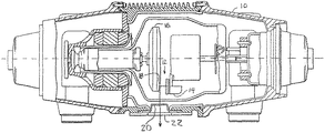
次に、図1を参照すると、従来のCT管組立体10の断面図が示される。CTイメージングシステムは、360度画像を生成するために種々の速度で回転するガントリを含む。ガントリは、単一の陰極14と陽極16との間の真空間隙12にX線を発生するCT管組立体10を含む。X線を発生するために、真空間隙12の両端に高電位が生成され、電子ビームの形態で電子が陰極14から陽極16の単一ターゲット18に照射可能となる。電子の放出において、陰極14内に含まれるフィラメントが加熱され、そこに電流を通すことにより白熱化される。高電圧電位により電子が加速されて、ターゲット18へ入射し、これにより電子は急激に減速されて、X線を放射してCT管ウィンドウ20を透過するX線ビームを形成する。
Referring now to FIG. 1, a cross-sectional view of a conventional
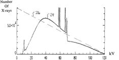
CT管ウィンドウ20を透過した後、X線ビームは単一のフィルタ22を介してフィルタ処理される。フィルタ22は、所定レベルより低いエネルギーレベルを有する低エネルギーX線数を低減し、従って患者に対するX線曝露が低減される。X線数と対応するエネルギーレベルの患者透過前エネルギースペクトルグラフの実施例を図2に示す。フィルタ後のスペクトル曲線24は、フィルタ前のスペクトル曲線26にほぼ重なる。スペクトル曲線24のピークは1つであり、40KeVより低いエネルギーレベルに対応するX線数は、フィルタ22によって吸収されるため顕著に減少している点に留意されたい。
After passing through the
フィルタ後のX線は患者の一部を透過し、X線検出器アレイにより検出される。X線が患者を透過すると、検出器アレイに入射する前に減弱する。X線減弱測定値は、そこでの減弱に応じて変化するエネルギーレベルを有する、受信したX線が生成する電気信号応答に対応してX線検出器により生成される。X線画像は減弱測定値に応答して再構成される。 The filtered X-rays pass through a portion of the patient and are detected by an X-ray detector array. As x-rays pass through the patient, they are attenuated before entering the detector array. X-ray attenuation measurements are generated by an X-ray detector in response to an electrical signal response generated by the received X-ray having an energy level that varies with the attenuation therein. The x-ray image is reconstructed in response to the attenuation measurement.
X線検出器アレイは、1つのピークのエネルギースペクトルに応答してX線信号を生成する。検出器で受信されたX線数は、検出器の平均領域及び観察時間間隔全体にわたり積算されて積算信号を生成する。積算信号は、患者のスキャン対象物質の密度に直接関係する。当該技術分野で公知のように、結果として得られたエネルギースペクトル、及び固有の積算特性から同様の物質密度を識別することは困難である。
従って、CTスキャニングの有用性及び性能を向上させるために、異なるスキャン対象物質と異なるスキャン対象合成物質を識別するエネルギー識別のCTシステムを提供することが望まれる。また、CTシステムが、精密で明瞭な、且つ患者へのX線曝露が増加することがない、エネルギー識別が可能であることが望ましい。 Accordingly, in order to improve the usefulness and performance of CT scanning, it is desirable to provide an energy discriminating CT system that distinguishes between different scan target materials and different scan target synthetic materials. It is also desirable that the CT system be capable of energy discrimination that is precise and clear and does not increase patient x-ray exposure.
本発明はイメージングシステム内でエネルギー識別を行うシステム及び方法を提供する。イメージングシステム内でエネルギー識別を行うX線源が提供され、これは、電子を照射する陰極照射装置と、電子が入射すると複数のX線量エネルギーピークを有するX線ビームを生成するターゲットを有する陽極とを含む。 The present invention provides a system and method for performing energy discrimination within an imaging system. An X-ray source for energy identification within an imaging system is provided, comprising: a cathode irradiation device that irradiates electrons; an anode having a target that generates an X-ray beam having a plurality of X-dose energy peaks when the electrons are incident; including.
また、イメージングシステム内でエネルギー識別を実行する方法が提供され、これは電子の照射を含む。X線量エネルギーピークを有するX線ビームが生成される。X線ビームは被検体を通って配向され、受信される。複数のエネルギー識別特性を有するX線画像が、X線ビームに応答して生成される。 Also provided is a method for performing energy discrimination within an imaging system, which includes electron irradiation. An x-ray beam having an x-ray energy peak is generated. The x-ray beam is directed and received through the subject. An x-ray image having a plurality of energy discrimination characteristics is generated in response to the x-ray beam.
本発明の幾つかの利点の1つは、エネルギー識別が可能なシステムを提供することであり、これにより医療従事者は同様の密度を有する物質と合成物質を識別できる。その際、本発明により、改善された診断、検査、試験、評価目的の情報生成を増大させることができる。 One of several advantages of the present invention is to provide a system capable of energy discrimination, which allows medical personnel to distinguish between materials with similar densities and synthetic materials. In so doing, the present invention can increase the generation of information for improved diagnosis, inspection, testing and evaluation purposes.
本発明の別の利点は、異なる物質間での空間分解能及び低コントラスト解像度の改善を可能にすることであり、これによりスキャン対象物質の識別が更に容易になる。 Another advantage of the present invention is that it allows for improved spatial resolution and low contrast resolution between different materials, which further facilitates identification of the material to be scanned.
更に、本発明はエネルギー識別を提供すると共に、患者に対するX線曝露を最小限に抑える。 Furthermore, the present invention provides energy discrimination and minimizes X-ray exposure to the patient.
本発明自体は、付随する利点とともに、添付の図面と関連付けながら取り上げた以下の詳細な説明を参照することにより最もよく理解されるであろう。 The invention itself, together with attendant advantages, will be best understood by reference to the following detailed description taken in conjunction with the accompanying drawings.
本発明をより完全に理解するためには、添付図により詳細に示され、本発明の実施例によって以下に説明される実施形態を参照する必要がある。 For a more complete understanding of the present invention, reference should be made to the embodiments illustrated in detail in the accompanying drawings and described below by way of examples of the invention.
以下の図の各々において、同じ参照符号は同じ構成要素を表すのに用いられる。本発明をコンピュータ断層撮影(CT)イメージングシステム内でエネルギー識別を行うシステム及び方法に関して説明するが、以下の装置及び方法は様々な目的に適合させることが可能であり、次の用途、すなわち、MRIシステム、CTシステム、放射線治療システム、X線イメージングシステム、超音波システム、放射性イメージングシステム、磁気共鳴分光システム、及び当該技術分野で公知の他の用途に限定されるものではない。 In each of the following figures, the same reference numerals are used to represent the same components. While the present invention will be described with respect to systems and methods for performing energy discrimination within a computed tomography (CT) imaging system, the following apparatus and methods may be adapted for various purposes and will be used in the following applications: MRI. It is not limited to systems, CT systems, radiotherapy systems, X-ray imaging systems, ultrasound systems, radioactive imaging systems, magnetic resonance spectroscopy systems, and other applications known in the art.
以下の説明では、ある1つの構成された実施形態に関する様々な動作パラメータ及び構成要素が説明される。これらの特定のパラメータ及び構成要素は例証として含まれ、限定を意味するものではない。 In the following description, various operating parameters and components for one configured embodiment are described. These specific parameters and components are included as examples and are not meant to be limiting.
同様に、以下の説明において、用語「X線量エネルギーピーク」は、エネルギースペクトルグラフ及びこの中に含まれるピークの一般的な形を表す。エネルギースペクトルグラフは、X線エネルギーレベル及び各エネルギーレベルに対応するX線数のグラフである。X線量エネルギーピークは、エネルギーグラフ内で発生又は存在しうる散発性のスパイク、或いは少数又は有意でないデータを意味するものではない。更に詳細な説明に関しては、下記の図8の説明を参照されたい。 Similarly, in the following description, the term “X-dose energy peak” represents the general shape of the energy spectrum graph and the peaks contained therein. The energy spectrum graph is a graph of the X-ray energy level and the number of X-rays corresponding to each energy level. X-ray energy peaks do not mean sporadic spikes that may occur or exist in the energy graph, or few or insignificant data. For a more detailed description, see the description of FIG. 8 below.
図3を参照すると、本発明の実施形態によるX線源32を含むCTイメージングシステム30の斜視図が示される。イメージングシステム30は、X線源32及びエネルギー識別検出器40を含む回転内側部分36を有するガントリ34を含む。X線源32は、複数のX線量エネルギーピークを有するX線ビームを検出器40に向かって投射する。線源32及び検出器40は、動作可能な並進テーブル42の周囲を回転する。テーブル42は、線源32と検出器40の間のz軸に沿って並進し、ヘリカルスキャンを行う。医療患者44を透過した後のビームは、患者ボア46内で、検出器40で検出され、CTイメージを生成するのに用いられる投影データを生成する。
Referring to FIG. 3, a perspective view of a
次いで、図4を参照すると、本発明の実施形態によるエネルギー識別システム50を使用するイメージングシステム30の拡大断面ブロック図が示されている。エネルギー識別システム50は、線源32、検出器40、及びX線コントローラ52を含む。
Referring now to FIG. 4, an enlarged cross-sectional block diagram of an
一般に、動作中、線源32及び検出器40は中心軸53の周りを回転する。ビーム54は、複数の検出器素子56によって受信される。各検出器素子56は、入射X線ビーム54の強度に対応する電気信号を生成する。ビーム54は、患者44を透過すると減弱する。内側部分36の回転及び線源32の動作は、制御機構58によって制御される。制御機構58は、電力及びタイミング信号を線源32に供給するX線コントローラ52と、内側部分36の回転速度及び位置を制御するガントリモータコントローラ60とを含む。データ収集システム(DAS)62が、検出器素子56からのアナログデータをサンプリングし、後続の処理のためにアナログデータをデジタル信号に変換する。画像再構成装置64は、サンプリングされてデジタル化されたX線データをDAS62から受けとり、高速の画像再構成を行う。主コントローラ66は、CTイメージを大容量記憶装置68に格納する。
In general, during operation, the
X線源32及び検出器40は患者44などの撮像対象の被検体の周囲を回転し、その結果、被検体を交差するビーム角度が常に変化するようになる。あるガントリ角度での検出器40からの一群のX線減弱測定値、すなわち投影データは、「ビュー」と呼ばれる。被検体の「スキャン」は、X線源32及び検出器40の1回転の間に様々なガントリ角度で取得されるビューの集合を含む。アキシャルスキャンにおいて、投影データは処理され、被検体を透過して撮像された2次元スライスに対応するイメージを構成するようにする。
The
投影データの集合、すなわち一群の減弱測定値を表す投影データから画像を再構成する1つの方法は、「フィルタ補正逆投影法」と呼ばれる。このプロセスは、スキャンからの減弱測定値を、「CT値」又は「ハウンスフィールド単位」(HU)と呼ばれる、−1024〜+3072の範囲の離散的整数に変換する。これらのHUを用いて、減弱測定値に応答する態様で陰極線管又はコンピュータスクリーン表示上の対応するピクセルの輝度を制御する。例えば、空気の減弱測定値を−1000HUの整数値(暗いピクセルに相当する)に変換することができ、極めて稠密な骨物質の減弱測定値を+3000の整数値(明るいピクセルに相当)に変換することができる一方、水の減弱測定値を0HUの整数値(中間ピクセルに相当)に変換することができる。この整数変換、すなわち「スコアリング」により、医師又は技師がコンピュータ表示の輝度に基づき物質の密度を判断し、従って関心領域を位置付けて識別することが可能となる。 One method for reconstructing an image from a set of projection data, ie projection data representing a group of attenuation measurements, is called a “filtered backprojection method”. This process converts attenuation measurements from scans into discrete integers ranging from -1024 to +3072, called "CT values" or "Hounsfield units" (HU). These HUs are used to control the brightness of the corresponding pixels on the cathode ray tube or computer screen display in a manner that is responsive to attenuation measurements. For example, an attenuation measurement of air can be converted to an integer value of −1000 HU (corresponding to a dark pixel), and an attenuation measurement of extremely dense bone material can be converted to an integer value of +3000 (corresponding to a bright pixel). On the other hand, the attenuation measurement of water can be converted to an integer value of 0HU (corresponding to an intermediate pixel). This integer transformation, or “scoring”, allows the physician or engineer to determine the density of the material based on the brightness of the computer display and thus locate and identify the region of interest.
本発明の1つの実施形態において、図示されるように検出器40は第1の検出器アレイ70と第2の検出器アレイ72とを含む。第1のアレイ70は、CTスライスの解剖学的詳細を生成するために従来的な情報を収集することが可能であるように、シンチレータ検出器/フォトセンサ検出器とすることができる。第2のアレイ72は、テルル化カドミウム亜鉛検出器などの直接変換(DC)検出器とすることができ、X線カウントモード及びエネルギー識別モードで減弱X線をカウントし、且つ減弱X線エネルギーを測定するように構成される。
In one embodiment of the invention, the
減弱X線の数及びエネルギーは、物質の特性を識別するためのエネルギー識別を行う際に用いられる。ヨウ素、血液、カルシウム、又は当該技術分野で既知の他の物質の識別など、様々な組織物質の元素組成及び/又は密度を求めることができる。アレイ70及び72から得られた情報を重ね合わせて、解剖学的詳細及び/又は組織識別(物質の種類及び密度)の情報が完全に同一で重なり合った単一のイメージを生成することができる。 The number and energy of the attenuated X-rays are used when performing energy identification for identifying the characteristics of the substance. The elemental composition and / or density of various tissue materials can be determined, such as identification of iodine, blood, calcium, or other materials known in the art. The information obtained from the arrays 70 and 72 can be superimposed to produce a single image with exactly the same anatomical details and / or tissue identification (material type and density) information.
第2のアレイ72は、シングルスライス設計及び/又はマルチスライス設計とすることができる。マルチスライス設計は、広範な異なる組織物質の情報を提供することができる一方、マルチスライス設計は個別の基準に対する統計値を改善するために複数のスライス全体を統合することができる。第2のアレイ72がX線カウント及びエネルギー識別モードで用いられると、エネルギー識別には低いX線量が使用されることから、CT検査に加えられるX線量は最小限に抑えられる。通常のCTスキャンでは、エネルギー識別データを集めるために、総X線量又は通常のX線量を超えてより少量のX線が用いられる。通常のCTスキャンは、詳細な解剖学的データなどの詳細なデータを提供するために第1のアレイ70を用いて行われる。エネルギー識別データを集めるときには、組織識別特性などの物質識別特性を備えた重なりイメージを生成するために第2のアレイ72が使用される。 The second array 72 can be a single slice design and / or a multi-slice design. A multi-slice design can provide a wide range of different tissue material information, while a multi-slice design can consolidate entire slices to improve statistics for individual criteria. When the second array 72 is used in an X-ray count and energy identification mode, the X-ray dosage applied to the CT examination is minimized because a low X-ray dosage is used for energy identification. In a normal CT scan, a smaller amount of x-rays is used to collect energy identification data, beyond the total x-ray dose or the normal x-ray dose. A normal CT scan is performed using the first array 70 to provide detailed data, such as detailed anatomical data. When collecting energy identification data, the second array 72 is used to generate an overlapping image with material identification characteristics, such as tissue identification characteristics.
上述の実施形態は、例証の目的に過ぎない。少なくとも1つのアレイが、以下でX線量エネルギーレベルと呼ばれる、様々なエネルギーレベル又はエネルギーレベルの範囲のX線数を検出可能であることが望ましいが、任意の数のアレイを使用可能である。例えば、上述の実施形態において、アレイ72は、X線量エネルギーレベルを検出可能であり、検出するように構成されるが、アレイ70はそうではない。また、アレイ70及び72の各々は、種々の形式及びスタイルが可能であり、当該技術分野で公知の種々の構成とすることができる。 The above-described embodiments are for illustrative purposes only. While it is desirable for at least one array to be able to detect the number of X-rays at various energy levels or ranges of energy levels, hereinafter referred to as X-dose energy levels, any number of arrays can be used. For example, in the embodiments described above, array 72 is capable of detecting and configured to detect X-ray dose energy levels, but array 70 is not. Also, each of the arrays 70 and 72 can be in various forms and styles and can have various configurations known in the art.
検出器40の更に詳細な説明及びその可能な実施形態については、「A Hybrid Scintillator/Photo Sensor and Direct Conversion Detector」と題された、出願番号第10/064,775号を参照されたい。
For a more detailed description of
また、主コントローラ66は、オペレータコンソール70を介してオペレータからの指令及びスキャニングパラメータを受信する。表示装置72によってオペレータは主コントローラ66からの再構成画像及び他のデータの観察が可能となる。オペレータが提供したコマンド及びパラメータは、X線コントローラ52、ガントリモータコントローラ60、及びDAS62の動作において主コントローラ66によって使用される。更に、主コントローラ66は、テーブル42を並進させてガントリ34内で患者44を位置付けるテーブルモータコントローラ74を操作する。
The
X線コントローラ52、ガントリモータコントローラ60、画像再構成装置64、主コントローラ66、及びテーブルモータコントローラ74は、中央演算装置、メモリ(RAM及び/又はROM)、並びに関連する入力及び出力バスを有するコンピュータのようなマイクロプロセッサベースであるのが望ましい。X線コントローラ52、ガントリモータコントローラ60、画像再構成装置64、主コントローラ66、及びテーブルモータコントローラ74は、中央演算装置の一部とすることができ、或いは、図示されるように各々が独立型の構成要素とすることができる。
以下の実施形態において、陰極照射装置は、任意の電子照射装置又は構成要素に適用することができる。陰極照射装置は、陰極、X線管kVp、陰極照射面、陰極素子、又は当該技術分野で公知の他の電子照射装置又は構成要素に適用できる。 In the following embodiments, the cathode irradiation device can be applied to any electron irradiation device or component. The cathode irradiation device can be applied to a cathode, an X-ray tube kVp, a cathode irradiation surface, a cathode element, or other electron irradiation devices or components known in the art.
図5を参照すると、本発明の1つの実施形態による、陽極81の単一の回転ターゲット80を有するエネルギー識別システム50’の拡大断面ブロック図が示されている。第1の陰極照射装置82及び第2の陰極照射装置84は、ターゲット80で遮断されるように配向される電子を照射する。第1のkVpは第1の陰極照射装置82と陽極ターゲット80との間に存在し、これはエネルギーレベル当たりのX線数のほぼ直線状の第1のフィルタ前スペクトル曲線で表すことができる。第2のkVpは、第1のkVpとは異なり、第2の陰極照射装置と陽極ターゲット80との間に存在し、エネルギーレベル当たりのX線数のほぼ直線の第2のフィルタ前スペクトル曲線で表すことができる。フィルタ前スペクトル曲線は、当該技術分野で公知のクラメールの公式を用いて表すことができる。第1のkVpフィルタ前スペクトル曲線は、第2のkVpフィルタ前スペクトル曲線とは勾配が異なる。
Referring to FIG. 5, an enlarged cross-sectional block diagram of an energy identification system 50 'having a single
ターゲット80に衝突すると、X線ビーム85及び86の形でX線は生成され、回転フィルタ88を透過するよう配向される。回転フィルタ88は第1のフィルタ90及び第2のフィルタ92を含み、フィルタ90及び92の各々は異なるエネルギー吸収特性を有する。1つの回転フィルタが使用されるが、2つ又はそれ以上のフィルタを有する他のフィルタ装置を用いることもできる。1つの実施形態において、各フィルタ90及び92は、X線ビーム85及び86の各々に関連する所定エネルギーレベルより低いエネルギーレベルに相当するX線の透過を阻止する。実際にフィルタ90及び92は、上述の実施形態において、低域通過フィルタとして機能する。もちろん、フィルタは、帯域フィルタ、ノッチ・フィルタ、高域通過フィルタ、デジタル・フィルタ、又は当該技術分野で公知の他の種類のフィルタとして機能させることができる。
Upon impacting the
X線ビーム85及び86は、フィルタ90及び92を透過すると混合されて、複数のX線量エネルギーピークを有するフィルタ後ビーム93を生成するが、これは、装置82及び84が関連するエネルギーレベルで異なる電子量を生成すること、及びフィルタ90及び92の吸収特性が異なることに起因する。実際に、フィルタ90及び92は異なるエネルギー透過範囲を有し、所定のエネルギー範囲内のX線がフィルタ90及び92を透過できるようにすることができる。エネルギー透過範囲は任意の大きさとすることができ、且つ任意の1つ又は複数のエネルギーレベルに対応付けることができる。
X-ray beams 85 and 86 are mixed as they pass through
X線コントローラ52’は、装置82及び84に電気的に接続され、並びに、フィルタ88に結合してこれを回転させるフィルタ回転装置94に電気的に接続される。コントローラ52’は、装置82と84及びフィルタ90と92間をそれぞれ同期して遷移させる。コントローラ52’は、X線コントローラ52又は主コントローラ66の形式又は一体部分、別個のコントローラ、又は、当該技術分野で公知の他のコントローラとすることができる。
X-ray controller 52 'is electrically connected to
次いで、図6を参照すると、本発明の別の実施形態による二重陽極回転ターゲット100を有するエネルギー識別システム50’’の拡大断面ブロック図が示される。第1の陰極照射装置82’及び第2の陰極照射装置84’は、陽極106の第1の回転ターゲット102と第2の回転ターゲット104のそれぞれに遮断されるように配向される電子を照射する。図5の実施形態と同様の方法で、第1のkVpは第1の陰極照射装置82’と回転ターゲット102との間に存在し、第2のkVpは第2の陰極照射装置84’と回転ターゲット104との間に存在する。ターゲット102及び104に衝突すると、X線ビーム108の形でX線が生成されて回転フィルタ88を通って配向され、フィルタ88を出るとすぐに混合されてフィルタ後ビーム109を生成する。回転フィルタ88が使用されているが、1つ又は複数のフィルタを有する他の何らかのフィルタ装置を使用することができる。フィルタ90及び92は、移動式又は固定式のものとすることができる。ビーム109は、図8で最もよく見られるように2つ又はそれ以上のX線量エネルギーピークを有する。
Referring now to FIG. 6, an enlarged cross-sectional block diagram of an
図5の実施形態同様に、コントローラ52’は、照射装置82’及び84’に電気的に接続され、並びにフィルタ88に結合してこれを回転させるフィルタ回転装置94に電気的に接続される。コントローラ52’は、装置82’と84’及びフィルタ90と92間をそれぞれ同期して遷移させる。別の実施形態において、フィルタ90及び92は固定され、装置82’及び84’は同時に操作される。
Similar to the embodiment of FIG. 5, the
図5及び図6は本発明の2つの可能な実施形態を示すが、当業者であれば他の実施形態を容易に想定することができる。陽極ターゲット、陰極照射装置、及びフィルタはどのような数であってもよい。例えば、第1の陰極照射装置82及び第2の陰極照射装置84は、2つの異なるkVpを生成し遷移するように動作する、単一の陰極照射装置で置き換えることができる。また、2つより多い陰極照射装置及び/又はフィルタを用いて、任意の数のX線量エネルギーピークを有するビームを生成することができる。これらの実施例は以下に更に詳細に説明する。
5 and 6 show two possible embodiments of the present invention, other embodiments can be readily envisioned by those skilled in the art. There may be any number of anode targets, cathode irradiation devices, and filters. For example, the first
精度、分解能、及び明瞭度の目的のために、図5及び図6の実施形態に示されるように、少なくとも2つの陰極照射装置と少なくとも2つのフィルタとを有することが望ましいが、それぞれに種々の数を用いることが可能である。 For accuracy, resolution, and clarity purposes, it is desirable to have at least two cathode illuminators and at least two filters, as shown in the embodiments of FIGS. Numbers can be used.
本発明の別の組の実施形態においては、図5及び図6の実施形態は、単一の陰極照射装置を回転フィルタ88と組み合わせて用いるように変更される。第1のフィルタ90と第2のフィルタ92とを、単一のX線ビームに対して交互に用いて、二重ピークエネルギースペクトルを有する患者透過後のX線ビームが生成される。単一の陰極照射装置は、急激に変化するkVpを有することができ、これは遷移又は回転フィルタと連動して用いることができる。
In another set of embodiments of the present invention, the embodiment of FIGS. 5 and 6 is modified to use a single cathode irradiation device in combination with a rotating filter 88. The first filter 90 and the
本発明の更に別の1組の実施形態においては、図5及び図6の実施形態は、陰極照射装置82、82’、84、84’が、回転フィルタ88の代わりに単一の固定フィルタと連動して使用されるように変更される。陰極照射装置82と84、及び陰極照射装置82’と84’をそれぞれ交互に用いて、エネルギーレベル当たりのX線数の異なるエネルギースペクトルプロファイル又は分布を有するX線ビームが生成される。
In yet another set of embodiments of the present invention, the embodiment of FIGS. 5 and 6 includes a
次に図7を参照すると、本発明の実施形態によるイメージングシステムにおけるエネルギー識別の方法の論理フロー図が示されている。簡単にするために、図7の方法は図5及び図6の実施形態に関して説明するが、上述の実施形態に限定されるものではない。 Referring now to FIG. 7, a logic flow diagram of a method for energy identification in an imaging system according to an embodiment of the present invention is shown. For simplicity, the method of FIG. 7 will be described with respect to the embodiments of FIGS. 5 and 6, but is not limited to the embodiments described above.
ステップ110において、上述のように、照射装置82、82’、84、84’などの1つ又は複数の陰極照射装置が電子を照射し、ターゲット80、100,104などの1つ又は複数の陽極ターゲットに入射する。
In step 110, as described above, one or more cathode irradiation devices, such as
ステップ112において、ビーム86及び108などのX線ビームが、複数のX線量エネルギーピークを有して生成される。例えば、第1のX線量エネルギーピーク116を有する第1のX線ビーム114、及び第2のX線量エネルギーピーク120を有する第2のX線ビーム118を生成することができ、ビーム114及び118は図6に最もよく示され、ピーク116及び120は図8の患者透過前のエネルギースペクトルグラフに最もよく示される。第1のX線量エネルギーピーク116及び第2のX線量エネルギーピーク120は、各陰極照射装置82’及び84’のそれぞれのkVpにより生成され、フィルタ90及び92により各X線ビーム108をフィルタ処理する。
In step 112, an x-ray beam, such as
この説明された実施形態において、エネルギースペクトルグラフは1組のピーク116及び120しか有さないが、エネルギースペクトルグラフは、陰極照射装置、フィルタ、及び陰極照射装置とフィルタの相関する数を変更することにより、任意の数のピークを有することができる。ピーク116及び120は、図示されるように所定のエネルギービン122及び124に対応することができ、これはX線量が有意に低減した1つ又は複数の分離ゾーン126(1つのみを図示)によって分離される。ビン122及び124、及び分離ゾーン126は、同様の物質エネルギー密度を有する物質を正確に識別するのに役立つ。
In this illustrated embodiment, the energy spectrum graph has only one set of
図7を再び参照すると、ステップ128において回転フィルタ88によりX線ビームがフィルタ処理される。コントローラ52’は第1のフィルタ90と第2のフィルタ92の間を遷移する。コントローラ52’は、患者44のスキャン中の各ビューにつき少なくとも1回はフィルタ90と92との間を遷移する。
Referring back to FIG. 7, the x-ray beam is filtered by the rotary filter 88 at step 128. The
ステップ130において、X線ビームは混合され、ビーム93及び109などの、複数のX線量エネルギーピークを有するフィルタ後X線ビームを生成する。
In
ステップ132において、フィルタ後X線ビームは患者44の少なくとも一部を透過して配向される。
In
ステップ134において、検出器40はフィルタ後X線ビームを受信し、これに応答して、エネルギーレベル当たりのX線数のような内包する物質エネルギー密度識別情報を有するX線信号を生成する。X線検出器40は、ピーク116及び120の各々に対応するX線ビームのX線量エネルギーレベルを測定することができ、エネルギービン122及び124に対応するX線量エネルギーレベルを測定することができ、同様のエネルギー密度を有する複数の物質のエネルギー識別を容易にするのに役立つ。検出器40又は当該技術分野で公知の他の信号調整装置は、望ましくない所定のエネルギー密度値をフィルタ処理して除去することにより、X線量エネルギーピーク間の分離が効果的に増幅されるようX線信号を信号調整することができる。
In
ステップ136において、システム30は、イメージのコントラストレベル、輝度レベル、色ばらつき、又は当該技術分野で公知の他の識別特性などといった、複数のエネルギー密度識別特性を有するX線イメージを、X線信号に応答して生成する。
In
ステップ138において、患者44のスキャンされた部分の物質及び物質密度を識別する。物質及び物質密度は、医療従事者、主コントローラ66、又は当該技術分野で公知の他の何らかの装置又は技術により求めることができる。複数のX線エネルギーピークを有することにおいて、各物質又は合成物質が異なるX線エネルギーピーク分布を示すことから、同じ密度を有する物質又は合成物質は容易に識別することができる。
In
X線エネルギーピーク分布は更に、異なるイメージ物質識別特性を生成するのに用いることができる。例えば、第1の合成物質は、各ピークに対する値の第1の大きさの集合を有する二重ピークエネルギースペクトルを示すことができ、第2の合成物質もまた、二重ピークエネルギースペクトルを示すことができるが、各ピーク値の第2の異なる大きさの集合を有する。2つの合成物質の大きさ、すなわちピーク値の差は、1つ又は複数の上述の識別特性を用いて、X線イメージに示すことができる。 The X-ray energy peak distribution can further be used to generate different image material identification characteristics. For example, the first synthetic material can exhibit a double peak energy spectrum having a first magnitude set of values for each peak, and the second synthetic material can also exhibit a double peak energy spectrum. Can have a second different set of sizes for each peak value. The magnitude of the two synthetic materials, i.e. the difference in peak values, can be shown in the X-ray image using one or more of the above-mentioned discriminating characteristics.
上述の段階は、例証としての実施例を意図するものであり、各ステップは同期し、連続し、同時に行うことができ、或いは、用途に応じた異なる順序で実施することができる。 The above-described steps are intended as illustrative examples, and the steps can be performed synchronously, sequentially, simultaneously, or in different orders depending on the application.
本発明は、同様のエネルギー密度を有する物質及び合成物質の識別を容易にするための、エネルギー識別システム及び方法を提供する。本発明は、高い動作性能と、空間分解能及び低コントラスト解像度の改善をもたらすと共に、患者へのX線曝露を最小限に抑えることができる。 The present invention provides an energy identification system and method for facilitating identification of materials having similar energy densities and synthetic materials. The present invention can provide high operating performance and improved spatial and low contrast resolution while minimizing patient X-ray exposure.
上述の装置は、当業者には様々な目的に適合させることができ、制御システム又は他の伝達システムに限定されない。また、上述の発明は、添付の請求項により企図される本発明の精神及び範囲から逸脱することなく変更することができる。 The devices described above can be adapted to various purposes by those skilled in the art and are not limited to control systems or other transmission systems. Also, the invention described above may be modified without departing from the spirit and scope of the invention as contemplated by the appended claims.
32 X線源
50’ エネルギー識別システム
52’ X線コントローラ
80 ターゲット
82’ 第1の陰極照射装置
84 第2の陰極照射装置
88 回転フィルタ
90 フィルタ
94 フィルタ回転装置
32 X-ray source 50 'Energy identification system 52'
Claims (10)
前記複数の電子が入射し、第1及び第2のX線ビームが生成される向きに配向されたターゲットを有する、単一の回転陽極と、
前記第1及び第2のX線ビームを同時にフィルタリングし、複数のエネルギーレベルで前記第1及び第2のX線のピークとして規定される複数のX線量エネルギーピークを同時に有するX線分布のフィルタ後のX線ビームを生成する第1及び第2のフィルタを備える回転フィルタと、
を含み、
前記第1及び第2のX線ビーム及び前記第1及び第2のフィルタとの間が同期して遷移する、イメージングシステム内でネルギー識別を行うX線源。 A plurality of cathode irradiation devices for irradiating a plurality of electrons;
A single rotating anode having a target oriented in a direction in which the plurality of electrons are incident and first and second X-ray beams are generated;
Simultaneously filtering said first and second X-ray beam, after the X-ray distribution with a plurality of X-ray dose energy peaks defined by a plurality of energy levels as a peak of the first and second X-ray at the same time filter A rotary filter comprising first and second filters for generating an X-ray beam of
Only including,
An X-ray source for performing energy discrimination in an imaging system in which the first and second X-ray beams and the first and second filters transition synchronously .
第1の複数の電子を照射する第1の陰極照射装置(82)と、
第2の複数の電子を照射する第2の陰極照射装置(84)と、
を含むことを特徴とする請求項1に記載のX線源。 The plurality of cathode irradiation devices,
A first cathode irradiation device (82) for irradiating a first plurality of electrons;
A second cathode irradiation device (84) for irradiating a second plurality of electrons;
The X-ray source according to claim 1, comprising:
前記第1のフィルタと前記第2のフィルタとが、前記第1のX線ビームに対して交互に用いられ、
前記第1のフィルタと前記第2のフィルタとが、前記第2のX線ビームに対して交互に用いられる、請求項1乃至3のいずれかに記載のX線源。 The first and second filters are low-pass filters;
The first filter and the second filter are alternately used for the first X-ray beam;
And said first filter and said second filter, Ru is used alternately to said second X-ray beam, X-ray source according to any one of claims 1 to 3.
前記少なくとも1つのX線ビームを受信し、物質エネルギー識別情報を有するX線信号を生成するエネルギー識別検出器(40)と、
を含むイメージングシステム。 X-ray source (32) according to any of claims 1 to 6,
An energy identification detector (40) for receiving the at least one X-ray beam and generating an X-ray signal having material energy identification information;
Including imaging system.
前記フィルタ回転装置に電気的に結合され、該回転フィルタを回転させるコントローラ(52)と、
を更に含む請求項7に記載のシステム。 A filter rotating device (94) coupled to the rotating filter;
A controller (52) electrically coupled to the filter rotation device for rotating the rotation filter;
The system of claim 7 further comprising:
The system according to claim 7, further comprising an X-ray detector for measuring a plurality of X-ray dose energy levels of the at least one X-ray beam.
Applications Claiming Priority (2)
| Application Number | Priority Date | Filing Date | Title |
|---|---|---|---|
| US10/250,132 | 2003-06-05 | ||
| US10/250,132 US7120222B2 (en) | 2003-06-05 | 2003-06-05 | CT imaging system with multiple peak x-ray source |
Publications (3)
| Publication Number | Publication Date |
|---|---|
| JP2004363109A JP2004363109A (en) | 2004-12-24 |
| JP2004363109A5 JP2004363109A5 (en) | 2009-10-08 |
| JP4831556B2 true JP4831556B2 (en) | 2011-12-07 |
Family
ID=33489129
Family Applications (1)
| Application Number | Title | Priority Date | Filing Date |
|---|---|---|---|
| JP2004167147A Expired - Fee Related JP4831556B2 (en) | 2003-06-05 | 2004-06-04 | CT imaging system with multi-peak X-ray source |
Country Status (3)
| Country | Link |
|---|---|
| US (2) | US7120222B2 (en) |
| JP (1) | JP4831556B2 (en) |
| DE (1) | DE102004027092A1 (en) |
Families Citing this family (70)
| Publication number | Priority date | Publication date | Assignee | Title |
|---|---|---|---|---|
| GB0525593D0 (en) | 2005-12-16 | 2006-01-25 | Cxr Ltd | X-ray tomography inspection systems |
| US8451974B2 (en) | 2003-04-25 | 2013-05-28 | Rapiscan Systems, Inc. | X-ray tomographic inspection system for the identification of specific target items |
| US8837669B2 (en) | 2003-04-25 | 2014-09-16 | Rapiscan Systems, Inc. | X-ray scanning system |
| US8243876B2 (en) | 2003-04-25 | 2012-08-14 | Rapiscan Systems, Inc. | X-ray scanners |
| US8223919B2 (en) | 2003-04-25 | 2012-07-17 | Rapiscan Systems, Inc. | X-ray tomographic inspection systems for the identification of specific target items |
| US7949101B2 (en) * | 2005-12-16 | 2011-05-24 | Rapiscan Systems, Inc. | X-ray scanners and X-ray sources therefor |
| US9113839B2 (en) | 2003-04-25 | 2015-08-25 | Rapiscon Systems, Inc. | X-ray inspection system and method |
| US7869862B2 (en) * | 2003-10-15 | 2011-01-11 | Varian Medical Systems, Inc. | Systems and methods for functional imaging using contrast-enhanced multiple-energy computed tomography |
| US20050082491A1 (en) * | 2003-10-15 | 2005-04-21 | Seppi Edward J. | Multi-energy radiation detector |
| US7649981B2 (en) * | 2003-10-15 | 2010-01-19 | Varian Medical Systems, Inc. | Multi-energy x-ray source |
| US7397904B2 (en) * | 2005-05-11 | 2008-07-08 | Varian Medical Systems Technologies, Inc. | Asymmetric flattening filter for x-ray device |
| CN101309643A (en) * | 2005-11-18 | 2008-11-19 | 皇家飞利浦电子股份有限公司 | Systems and methods using x-ray tube spectra for computed tomography applications |
| DE102006002037A1 (en) * | 2006-01-16 | 2007-07-19 | Siemens Ag | Method for processing diagnostic image data |
| JP4769089B2 (en) * | 2006-01-31 | 2011-09-07 | 株式会社東芝 | X-ray equipment |
| US7606349B2 (en) * | 2006-02-09 | 2009-10-20 | L-3 Communications Security and Detection Systems Inc. | Selective generation of radiation at multiple energy levels |
| JP2009532161A (en) * | 2006-04-07 | 2009-09-10 | コーニンクレッカ フィリップス エレクトロニクス エヌ ヴィ | Dual spectrum x-ray tube with switching focus and filter |
| CN101074937B (en) * | 2006-05-19 | 2010-09-08 | 清华大学 | Energy spectrum modulator, method and apparatus for discriminating material and image processing method |
| EP2021783B1 (en) * | 2006-05-31 | 2013-03-13 | L-3 Communications Security and Detection Systems, Inc. | Dual energy x-ray source |
| US20080037703A1 (en) * | 2006-08-09 | 2008-02-14 | Digimd Corporation | Three dimensional breast imaging |
| US7483518B2 (en) * | 2006-09-12 | 2009-01-27 | Siemens Medical Solutions Usa, Inc. | Apparatus and method for rapidly switching the energy spectrum of diagnostic X-ray beams |
| US7852979B2 (en) * | 2007-04-05 | 2010-12-14 | General Electric Company | Dual-focus X-ray tube for resolution enhancement and energy sensitive CT |
| JP5460318B2 (en) * | 2007-07-19 | 2014-04-02 | 株式会社日立メディコ | X-ray generator and X-ray CT apparatus using the same |
| CN101358936B (en) | 2007-08-02 | 2011-03-16 | 同方威视技术股份有限公司 | Method and system for discriminating material by double-perspective multi energy transmission image |
| CN101779267A (en) * | 2007-08-16 | 2010-07-14 | 皇家飞利浦电子股份有限公司 | Hybrid design of an anode disk structure for high power x-ray tube configurations of the rotary-anode type |
| DE102007041107B4 (en) | 2007-08-30 | 2009-10-29 | Siemens Ag | X-ray machine |
| US7742566B2 (en) * | 2007-12-07 | 2010-06-22 | General Electric Company | Multi-energy imaging system and method using optic devices |
| ATE528971T1 (en) * | 2007-12-21 | 2011-10-15 | Elekta Ab | X-RAY APPARATUS |
| WO2010024821A1 (en) * | 2008-08-29 | 2010-03-04 | Analogic Corporation | Multi-cathode x-ray tubes with staggered focal spots, and systems and methods using same |
| US8503616B2 (en) * | 2008-09-24 | 2013-08-06 | Varian Medical Systems, Inc. | X-ray tube window |
| DE102008049049A1 (en) * | 2008-09-26 | 2010-04-08 | Siemens Aktiengesellschaft | X-ray computed tomography system for tomographic representation of patient, has electron emitter supplied with high voltage potential so that electrons generate different energy spectra based on emitted acceleration voltage |
| US7792241B2 (en) * | 2008-10-24 | 2010-09-07 | General Electric Company | System and method of fast KVP switching for dual energy CT |
| DE102008056891B4 (en) * | 2008-11-12 | 2012-04-12 | Siemens Aktiengesellschaft | A computed tomography device for performing a spiral scan and method of controlling a computed tomography device |
| RU2540327C2 (en) * | 2008-11-25 | 2015-02-10 | Конинклейке Филипс Электроникс Н.В. | X-ray anode |
| US7974383B2 (en) * | 2008-12-09 | 2011-07-05 | General Electric Company | System and method to maintain target material in ductile state |
| US7881425B2 (en) * | 2008-12-30 | 2011-02-01 | General Electric Company | Wide-coverage x-ray source with dual-sided target |
| WO2011018750A1 (en) * | 2009-08-11 | 2011-02-17 | Koninklijke Philips Electronics N.V. | Rotary anode for a rotary anode x-ray tube and method for manufacturing a rotary anode |
| JP2011067333A (en) * | 2009-09-25 | 2011-04-07 | Fujifilm Corp | Radiation imaging apparatus and imaging control device |
| US8571181B2 (en) * | 2009-11-02 | 2013-10-29 | Xrsciences Llc | Rapidly switching dual energy X-ray source |
| US9271689B2 (en) * | 2010-01-20 | 2016-03-01 | General Electric Company | Apparatus for wide coverage computed tomography and method of constructing same |
| WO2012007881A2 (en) * | 2010-07-13 | 2012-01-19 | Koninklijke Philips Electronics N.V. | X-ray tube arrangement with toroidal rotatable filter arrangement and computed tomography device comprising same |
| US20120087464A1 (en) * | 2010-10-09 | 2012-04-12 | Fmi Technologies, Inc. | Multi-source low dose x-ray ct imaging aparatus |
| DE102010042683B4 (en) * | 2010-10-20 | 2013-11-14 | Siemens Aktiengesellschaft | Device and method for generating X-radiation and computer program and data carrier |
| US8737567B2 (en) | 2011-01-27 | 2014-05-27 | Medtronic Navigation, Inc. | Image acquisition optimization |
| US9101272B2 (en) * | 2011-03-24 | 2015-08-11 | Jefferson Radiology, P.C. | Fixed anterior gantry CT shielding |
| US9424958B2 (en) * | 2011-06-06 | 2016-08-23 | Koninklijke Philips N.V. | Multiple focal spot X-ray radiation filtering |
| JP5823178B2 (en) * | 2011-06-14 | 2015-11-25 | 株式会社東芝 | X-ray CT system |
| US9324536B2 (en) * | 2011-09-30 | 2016-04-26 | Varian Medical Systems, Inc. | Dual-energy X-ray tubes |
| US9069092B2 (en) | 2012-02-22 | 2015-06-30 | L-3 Communication Security and Detection Systems Corp. | X-ray imager with sparse detector array |
| BR112014032123A2 (en) * | 2012-06-29 | 2017-06-27 | Koninklijke Philips Nv | detector data processing apparatus, detector data processing method, x-ray imaging system, computer program element for controlling an apparatus, and computer readable medium |
| JP6188470B2 (en) * | 2013-07-24 | 2017-08-30 | キヤノン株式会社 | Radiation generator and radiation imaging system using the same |
| US20150036792A1 (en) * | 2013-08-01 | 2015-02-05 | Korea Advanced Institute Of Science And Technology | Computed tomography apparatus, and method of generating image by using computed tomography apparatus |
| JP6266284B2 (en) * | 2013-09-19 | 2018-01-24 | 東芝メディカルシステムズ株式会社 | X-ray diagnostic equipment |
| DE102014203465A1 (en) * | 2014-02-26 | 2015-08-27 | Siemens Aktiengesellschaft | Method for selecting a radiation form filter and X-ray imaging system |
| JP2015180859A (en) * | 2014-03-05 | 2015-10-15 | 株式会社東芝 | photon counting CT apparatus |
| US9976971B2 (en) * | 2014-03-06 | 2018-05-22 | United Technologies Corporation | Systems and methods for X-ray diffraction |
| TWI629474B (en) * | 2014-05-23 | 2018-07-11 | 財團法人工業技術研究院 | X-ray source and phase contrast x-ray imaging method |
| US9991014B1 (en) * | 2014-09-23 | 2018-06-05 | Daniel Gelbart | Fast positionable X-ray filter |
| US10405813B2 (en) * | 2015-02-04 | 2019-09-10 | Dental Imaging Technologies Corporation | Panoramic imaging using multi-spectral X-ray source |
| CN104882350A (en) * | 2015-06-11 | 2015-09-02 | 杭州与盟医疗技术有限公司 | X-ray ball tube system with multienergy and larger coverage area |
| JP6772289B2 (en) | 2016-03-24 | 2020-10-21 | コーニンクレッカ フィリップス エヌ ヴェKoninklijke Philips N.V. | X-ray generator |
| EP3434079A1 (en) * | 2016-03-24 | 2019-01-30 | Koninklijke Philips N.V. | Apparatus for generating x-rays |
| US11282668B2 (en) * | 2016-03-31 | 2022-03-22 | Nano-X Imaging Ltd. | X-ray tube and a controller thereof |
| DE102017000994B4 (en) * | 2017-02-01 | 2019-11-21 | Esspen Gmbh | CT Scanner |
| JP6885803B2 (en) * | 2017-06-27 | 2021-06-16 | ゼネラル・エレクトリック・カンパニイ | Radiation imaging device and imaging method |
| DE102019213983A1 (en) * | 2019-09-13 | 2021-03-18 | Fraunhofer-Gesellschaft zur Förderung der angewandten Forschung e.V. | DEVICE AND METHOD FOR DETERMINING AN ACQUISITION PARAMETERS AND / OR FOR PROVIDING A MAINTENANCE RECOMMENDATION FOR A COMPUTER TOMOGRAPHY SYSTEM |
| US11293884B2 (en) * | 2020-01-07 | 2022-04-05 | The Boeing Company | Multi source backscattering |
| CN111243916B (en) * | 2020-01-19 | 2021-10-29 | 中国科学院电子学研究所 | Anode, preparation method thereof and cathode emission testing device |
| CN111429410B (en) * | 2020-03-13 | 2023-09-01 | 杭州电子科技大学 | Object X-ray image material discrimination system and method based on deep learning |
| US11071506B1 (en) * | 2020-04-28 | 2021-07-27 | Wisconsin Alumni Research Foundation | X-ray imaging device providing enhanced spatial resolution by energy encoding |
| JP7451326B2 (en) | 2020-06-29 | 2024-03-18 | キヤノンメディカルシステムズ株式会社 | X-ray diagnostic equipment |
Family Cites Families (44)
| Publication number | Priority date | Publication date | Assignee | Title |
|---|---|---|---|---|
| NL58621C (en) * | 1939-10-14 | |||
| US2597498A (en) * | 1948-12-10 | 1952-05-20 | Joseph V Kerkhoff | X-ray tube |
| US3610984A (en) * | 1967-12-28 | 1971-10-05 | Tokyo Shibaura Electric Co | Rotating-anode x-ray tube with multiple focal areas |
| US4065689A (en) * | 1974-11-29 | 1977-12-27 | Picker Corporation | Dual filament X-ray tube |
| US4686695A (en) * | 1979-02-05 | 1987-08-11 | Board Of Trustees Of The Leland Stanford Junior University | Scanned x-ray selective imaging system |
| US4445226A (en) * | 1981-05-05 | 1984-04-24 | The Board Of Trustees Of The Leland Stanford Junior University | Multiple-energy X-ray subtraction imaging system |
| EP0081227B1 (en) * | 1981-12-07 | 1987-03-18 | Albert Macovski | Energy-selective x-ray recording and readout system |
| JPH0678501B2 (en) * | 1985-11-21 | 1994-10-05 | 大日本インキ化学工業株式会社 | Aqueous coating composition |
| US4963746A (en) * | 1986-11-25 | 1990-10-16 | Picker International, Inc. | Split energy level radiation detection |
| US4823371A (en) * | 1987-08-24 | 1989-04-18 | Grady John K | X-ray tube system |
| JPH01204649A (en) * | 1988-02-12 | 1989-08-17 | Toshiba Corp | X-ray photographing device |
| EP0432730B1 (en) * | 1989-12-14 | 1999-08-04 | Aloka Co. Ltd. | Bone mineral content measuring apparatus |
| US5335255A (en) * | 1992-03-24 | 1994-08-02 | Seppi Edward J | X-ray scanner with a source emitting plurality of fan beams |
| US5485492A (en) * | 1992-03-31 | 1996-01-16 | Lunar Corporation | Reduced field-of-view CT system for imaging compact embedded structures |
| DE4230880A1 (en) * | 1992-09-16 | 1994-03-17 | Philips Patentverwaltung | X-ray generator for supplying an X-ray tube with at least two electron sources |
| JP3449561B2 (en) * | 1993-04-19 | 2003-09-22 | 東芝医用システムエンジニアリング株式会社 | X-ray CT system |
| US5511105A (en) * | 1993-07-12 | 1996-04-23 | Siemens Aktiengesellschaft | X-ray tube with multiple differently sized focal spots and method for operating same |
| US5490196A (en) * | 1994-03-18 | 1996-02-06 | Metorex International Oy | Multi energy system for x-ray imaging applications |
| US5661774A (en) * | 1996-06-27 | 1997-08-26 | Analogic Corporation | Dual energy power supply |
| US5943388A (en) * | 1996-07-30 | 1999-08-24 | Nova R & D, Inc. | Radiation detector and non-destructive inspection |
| US6008493A (en) * | 1997-05-30 | 1999-12-28 | Adac Laboratories | Method and apparatus for performing correction of emission contamination and deadtime loss in a medical imaging system |
| US6410920B1 (en) * | 1997-05-30 | 2002-06-25 | Adac Laboratories | Method and apparatus for performing correction of emission contamination and deadtime loss in a medical imaging system |
| DE19729414A1 (en) * | 1997-07-09 | 1999-02-11 | Siemens Ag | Medical radiation screening system |
| DE19802668B4 (en) * | 1998-01-24 | 2013-10-17 | Smiths Heimann Gmbh | X-ray generator |
| US6307918B1 (en) * | 1998-08-25 | 2001-10-23 | General Electric Company | Position dependent beam quality x-ray filtration |
| US6226352B1 (en) * | 1998-09-08 | 2001-05-01 | Veritas Pharmaceuticals, Inc. | System and method for radiographic imaging of tissue |
| US6229870B1 (en) * | 1998-11-25 | 2001-05-08 | Picker International, Inc. | Multiple fan beam computed tomography system |
| US6285740B1 (en) * | 1999-10-13 | 2001-09-04 | The United States Of America As Represented By The Secretary Of The Navy | Dual energy x-ray densitometry apparatus and method using single x-ray pulse |
| US6246747B1 (en) * | 1999-11-01 | 2001-06-12 | Ge Lunar Corporation | Multi-energy x-ray machine with reduced tube loading |
| US6333968B1 (en) * | 2000-05-05 | 2001-12-25 | The United States Of America As Represented By The Secretary Of The Navy | Transmission cathode for X-ray production |
| DE10048775B4 (en) * | 2000-09-29 | 2006-02-02 | Siemens Ag | X-ray computed tomography device |
| US6553096B1 (en) * | 2000-10-06 | 2003-04-22 | The University Of North Carolina Chapel Hill | X-ray generating mechanism using electron field emission cathode |
| AU2002246736A1 (en) * | 2000-10-24 | 2002-08-06 | The Johns Hopkins University | Method and apparatus for multiple-projection, dual-energy x-ray absorptiometry scanning |
| US6614878B2 (en) * | 2001-01-23 | 2003-09-02 | Fartech, Inc. | X-ray filter system for medical imaging contrast enhancement |
| JP2002263091A (en) * | 2001-03-07 | 2002-09-17 | Tomoki Yamazaki | Stereofluororoentgenography and x-ray bulb for stereofluororoentgenograph |
| US6480572B2 (en) * | 2001-03-09 | 2002-11-12 | Koninklijke Philips Electronics N.V. | Dual filament, electrostatically controlled focal spot for x-ray tubes |
| US7636413B2 (en) * | 2002-04-16 | 2009-12-22 | General Electric Company | Method and apparatus of multi-energy imaging |
| US6760407B2 (en) * | 2002-04-17 | 2004-07-06 | Ge Medical Global Technology Company, Llc | X-ray source and method having cathode with curved emission surface |
| US6597758B1 (en) * | 2002-05-06 | 2003-07-22 | Agilent Technologies, Inc. | Elementally specific x-ray imaging apparatus and method |
| US6947522B2 (en) * | 2002-12-20 | 2005-09-20 | General Electric Company | Rotating notched transmission x-ray for multiple focal spots |
| US6968030B2 (en) * | 2003-05-20 | 2005-11-22 | General Electric Company | Method and apparatus for presenting multiple pre-subject filtering profiles during CT data acquisition |
| JP3909048B2 (en) * | 2003-09-05 | 2007-04-25 | ジーイー・メディカル・システムズ・グローバル・テクノロジー・カンパニー・エルエルシー | X-ray CT apparatus and X-ray tube |
| US7003077B2 (en) * | 2003-10-03 | 2006-02-21 | General Electric Company | Method and apparatus for x-ray anode with increased coverage |
| US7065179B2 (en) * | 2003-11-07 | 2006-06-20 | General Electric Company | Multiple target anode assembly and system of operation |
-
2003
- 2003-06-05 US US10/250,132 patent/US7120222B2/en not_active Expired - Lifetime
-
2004
- 2004-06-02 DE DE102004027092A patent/DE102004027092A1/en not_active Withdrawn
- 2004-06-04 JP JP2004167147A patent/JP4831556B2/en not_active Expired - Fee Related
-
2006
- 2006-08-18 US US11/465,472 patent/US7778382B2/en not_active Expired - Fee Related
Also Published As
| Publication number | Publication date |
|---|---|
| US20060285645A1 (en) | 2006-12-21 |
| US7120222B2 (en) | 2006-10-10 |
| US20040247082A1 (en) | 2004-12-09 |
| DE102004027092A1 (en) | 2004-12-23 |
| US7778382B2 (en) | 2010-08-17 |
| JP2004363109A (en) | 2004-12-24 |
Similar Documents
| Publication | Publication Date | Title |
|---|---|---|
| JP4831556B2 (en) | CT imaging system with multi-peak X-ray source | |
| JP4361778B2 (en) | Method and apparatus for forming computed tomography (CT) scout images | |
| JP4949664B2 (en) | CT colonography system | |
| US9754387B2 (en) | System and method for improved energy series of images using multi-energy CT | |
| Buzug | Computed tomography | |
| JP5703014B2 (en) | Dual energy imaging with reduced sampling rate | |
| JP4347672B2 (en) | Method and apparatus for detecting abnormalities related to structure, perfusion and function | |
| US8311182B2 (en) | System and method of notch filtration for dual energy CT | |
| US7724865B2 (en) | System and method of optimizing a monochromatic representation of basis material decomposed CT images | |
| US8787519B2 (en) | System and method of optimizing a representation of dual energy spectral CT images | |
| US20040101090A1 (en) | Methods and apparatus for acquiring perfusion data | |
| JP4445221B2 (en) | Method and apparatus for performing a computed tomography scan | |
| US7187748B2 (en) | Multidetector CT imaging method and apparatus with reducing radiation scattering | |
| JP2008237908A (en) | Detection of thrombi in ct using energy discrimination | |
| JP4344191B2 (en) | Method and system for low-dose image simulation of an imaging system | |
| WO2007056574A2 (en) | Methods and apparatus for obtaining low-dose imaging | |
| WO2007074772A1 (en) | X-ray ct device | |
| US20120076258A1 (en) | Multiple materials for the enhancement of spectral notch filtration in spectral imaging | |
| EP3821811B1 (en) | Systems and methods for coherent scatter imaging using a segmented photon-counting detector for computed tomography | |
| Gunnarsson et al. | Principles behind Computed Tomography (CT) |
Legal Events
| Date | Code | Title | Description |
|---|---|---|---|
| A521 | Request for written amendment filed |
Free format text: JAPANESE INTERMEDIATE CODE: A523 Effective date: 20070528 |
|
| A621 | Written request for application examination |
Free format text: JAPANESE INTERMEDIATE CODE: A621 Effective date: 20070528 |
|
| A521 | Request for written amendment filed |
Free format text: JAPANESE INTERMEDIATE CODE: A523 Effective date: 20090825 |
|
| RD02 | Notification of acceptance of power of attorney |
Free format text: JAPANESE INTERMEDIATE CODE: A7422 Effective date: 20090825 |
|
| RD04 | Notification of resignation of power of attorney |
Free format text: JAPANESE INTERMEDIATE CODE: A7424 Effective date: 20090825 |
|
| A977 | Report on retrieval |
Free format text: JAPANESE INTERMEDIATE CODE: A971007 Effective date: 20100804 |
|
| A131 | Notification of reasons for refusal |
Free format text: JAPANESE INTERMEDIATE CODE: A131 Effective date: 20100810 |
|
| A521 | Request for written amendment filed |
Free format text: JAPANESE INTERMEDIATE CODE: A523 Effective date: 20100921 |
|
| TRDD | Decision of grant or rejection written | ||
| A01 | Written decision to grant a patent or to grant a registration (utility model) |
Free format text: JAPANESE INTERMEDIATE CODE: A01 Effective date: 20110830 |
|
| A01 | Written decision to grant a patent or to grant a registration (utility model) |
Free format text: JAPANESE INTERMEDIATE CODE: A01 |
|
| A61 | First payment of annual fees (during grant procedure) |
Free format text: JAPANESE INTERMEDIATE CODE: A61 Effective date: 20110913 |
|
| R150 | Certificate of patent or registration of utility model |
Ref document number: 4831556 Country of ref document: JP Free format text: JAPANESE INTERMEDIATE CODE: R150 Free format text: JAPANESE INTERMEDIATE CODE: R150 |
|
| FPAY | Renewal fee payment (event date is renewal date of database) |
Free format text: PAYMENT UNTIL: 20140930 Year of fee payment: 3 |
|
| R250 | Receipt of annual fees |
Free format text: JAPANESE INTERMEDIATE CODE: R250 |
|
| R250 | Receipt of annual fees |
Free format text: JAPANESE INTERMEDIATE CODE: R250 |
|
| R250 | Receipt of annual fees |
Free format text: JAPANESE INTERMEDIATE CODE: R250 |
|
| R250 | Receipt of annual fees |
Free format text: JAPANESE INTERMEDIATE CODE: R250 |
|
| R250 | Receipt of annual fees |
Free format text: JAPANESE INTERMEDIATE CODE: R250 |
|
| R250 | Receipt of annual fees |
Free format text: JAPANESE INTERMEDIATE CODE: R250 |
|
| LAPS | Cancellation because of no payment of annual fees |