JP4344191B2 - Method and system for low-dose image simulation of an imaging system - Google Patents
Method and system for low-dose image simulation of an imaging system Download PDFInfo
- Publication number
- JP4344191B2 JP4344191B2 JP2003280544A JP2003280544A JP4344191B2 JP 4344191 B2 JP4344191 B2 JP 4344191B2 JP 2003280544 A JP2003280544 A JP 2003280544A JP 2003280544 A JP2003280544 A JP 2003280544A JP 4344191 B2 JP4344191 B2 JP 4344191B2
- Authority
- JP
- Japan
- Prior art keywords
- image
- data
- noise
- simulated
- patient
- Prior art date
- Legal status (The legal status is an assumption and is not a legal conclusion. Google has not performed a legal analysis and makes no representation as to the accuracy of the status listed.)
- Expired - Fee Related
Links
- 238000000034 method Methods 0.000 title claims description 40
- 238000003384 imaging method Methods 0.000 title claims description 18
- 238000004088 simulation Methods 0.000 title description 2
- 230000005855 radiation Effects 0.000 claims description 35
- 238000002591 computed tomography Methods 0.000 claims description 18
- 238000012545 processing Methods 0.000 claims description 17
- 238000004590 computer program Methods 0.000 claims description 7
- 230000009467 reduction Effects 0.000 claims description 5
- 238000004891 communication Methods 0.000 claims description 4
- 230000002238 attenuated effect Effects 0.000 description 9
- 238000005259 measurement Methods 0.000 description 7
- 238000013170 computed tomography imaging Methods 0.000 description 6
- 230000008569 process Effects 0.000 description 5
- 238000013500 data storage Methods 0.000 description 4
- 238000010586 diagram Methods 0.000 description 3
- 206010073306 Exposure to radiation Diseases 0.000 description 2
- 230000008901 benefit Effects 0.000 description 2
- 238000006243 chemical reaction Methods 0.000 description 2
- 238000003745 diagnosis Methods 0.000 description 2
- 238000005286 illumination Methods 0.000 description 2
- 239000000463 material Substances 0.000 description 2
- 230000007246 mechanism Effects 0.000 description 2
- 238000012986 modification Methods 0.000 description 2
- 230000004048 modification Effects 0.000 description 2
- 238000011282 treatment Methods 0.000 description 2
- 238000004458 analytical method Methods 0.000 description 1
- 210000000988 bone and bone Anatomy 0.000 description 1
- 238000004364 calculation method Methods 0.000 description 1
- 230000007423 decrease Effects 0.000 description 1
- 230000005670 electromagnetic radiation Effects 0.000 description 1
- 238000011156 evaluation Methods 0.000 description 1
- 230000006870 function Effects 0.000 description 1
- 230000005802 health problem Effects 0.000 description 1
- 230000003902 lesion Effects 0.000 description 1
- 238000002595 magnetic resonance imaging Methods 0.000 description 1
- 239000013307 optical fiber Substances 0.000 description 1
- 238000011160 research Methods 0.000 description 1
- 230000004044 response Effects 0.000 description 1
- 238000005070 sampling Methods 0.000 description 1
- 239000000126 substance Substances 0.000 description 1
- 238000002604 ultrasonography Methods 0.000 description 1
- XLYOFNOQVPJJNP-UHFFFAOYSA-N water Substances O XLYOFNOQVPJJNP-UHFFFAOYSA-N 0.000 description 1
Images


Classifications
-
- G—PHYSICS
- G06—COMPUTING; CALCULATING OR COUNTING
- G06T—IMAGE DATA PROCESSING OR GENERATION, IN GENERAL
- G06T11/00—2D [Two Dimensional] image generation
- G06T11/003—Reconstruction from projections, e.g. tomography
- G06T11/008—Specific post-processing after tomographic reconstruction, e.g. voxelisation, metal artifact correction
-
- A—HUMAN NECESSITIES
- A61—MEDICAL OR VETERINARY SCIENCE; HYGIENE
- A61B—DIAGNOSIS; SURGERY; IDENTIFICATION
- A61B6/00—Apparatus for radiation diagnosis, e.g. combined with radiation therapy equipment
-
- A—HUMAN NECESSITIES
- A61—MEDICAL OR VETERINARY SCIENCE; HYGIENE
- A61B—DIAGNOSIS; SURGERY; IDENTIFICATION
- A61B6/00—Apparatus for radiation diagnosis, e.g. combined with radiation therapy equipment
- A61B6/58—Testing, adjusting or calibrating apparatus or devices for radiation diagnosis
- A61B6/582—Calibration
- A61B6/583—Calibration using calibration phantoms
-
- Y—GENERAL TAGGING OF NEW TECHNOLOGICAL DEVELOPMENTS; GENERAL TAGGING OF CROSS-SECTIONAL TECHNOLOGIES SPANNING OVER SEVERAL SECTIONS OF THE IPC; TECHNICAL SUBJECTS COVERED BY FORMER USPC CROSS-REFERENCE ART COLLECTIONS [XRACs] AND DIGESTS
- Y10—TECHNICAL SUBJECTS COVERED BY FORMER USPC
- Y10S—TECHNICAL SUBJECTS COVERED BY FORMER USPC CROSS-REFERENCE ART COLLECTIONS [XRACs] AND DIGESTS
- Y10S378/00—X-ray or gamma ray systems or devices
- Y10S378/901—Computer tomography program or processor
Description
本発明は、一般に画像形成システムに関し、より具体的には、より低い線量における画像のシミュレーションのための方法及びシステムを通して、画像形成システムのための照射効率を改善することに関する。 The present invention relates generally to imaging systems, and more particularly to improving illumination efficiency for imaging systems through methods and systems for simulating images at lower doses.
少なくとも1つの公知のコンピュータ断層撮影(CT)画像形成システムの構成において、X線源が、デカルト座標系のX−Y平面内に位置するように平行光にされた扇状のビームを照射し、該X−Y平面は、一般に「画像形成平面」と呼ばれる。各々の放射線検知器が検知器要素を含む放射線検知器のアレイが、この扇状ビームを受信するようにCTシステム内にある。患者などの被写体が、被写体を通過するX線ビームに曝されるように画像形成平面内に位置させられる。X線ビームが画像化されている被写体を通過すると、該X線ビームは放射線検知器のアレイの上に衝突する前に減衰される。検知器アレイで受信された減衰されたビームの放射線の強さは、被写体によるX線ビームの減衰に対応しており、各々の検知器要素は、該検知器要素の位置でのビームの減衰に対応する別々の電気信号を生成する。これらの電気信号がX線減衰測定値と呼ばれる。 In the configuration of at least one known computed tomography (CT) imaging system, an X-ray source irradiates a fan-shaped beam that has been collimated to lie in the XY plane of a Cartesian coordinate system, The XY plane is generally called an “image forming plane”. An array of radiation detectors, where each radiation detector includes a detector element, is in the CT system to receive this fan beam. A subject such as a patient is positioned in the image forming plane so as to be exposed to an X-ray beam passing through the subject. As the x-ray beam passes through the object being imaged, the x-ray beam is attenuated before impinging on the array of radiation detectors. The intensity of the attenuated beam radiation received at the detector array corresponds to the attenuation of the x-ray beam by the subject, and each detector element is responsible for the attenuation of the beam at the location of the detector element. A corresponding separate electrical signal is generated. These electrical signals are called X-ray attenuation measurements.
さらに、X線源及び検知器アレイは、ガントリを画像形成平面内に位置させた状態で、画像形成されるべき被写体の周りを回転することができるため、X線ビームが該被写体と交差する角度は、常に変化する。1つのガントリ角度における検知器アレイからのX線減衰測定値の一群、すなわち照射データは、「ビュー(視野)」と呼ばれる。被写体の「走査」は、X線源及び検知器アレイの1つの旋回の間に異なるガントリ角度において作られた一組のビューを含む。軸方向走査において、照射データは、被写体を通して取られた2次元のスライスに対応する画像を構成するように処理される。 In addition, the X-ray source and detector array can rotate around the subject to be imaged with the gantry positioned in the imaging plane so that the angle at which the X-ray beam intersects the subject. Always changes. A group of x-ray attenuation measurements from a detector array at one gantry angle, ie, irradiation data, is referred to as a “view”. A “scan” of an object includes a set of views made at different gantry angles during one rotation of the x-ray source and detector array. In the axial scan, the irradiation data is processed to construct an image corresponding to a two-dimensional slice taken through the subject.
1組の照射データから画像を再構成する1つの方法は、「フィルタ補正逆投影法」と呼ばれている。この処理は、走査からの減衰測定値を、「CT数」又は「ハンスフィールド単位」(HU)と呼ばれる、−1024から+3071までの範囲の個別の整数に変換する。これらのHUは、減衰測定値に対応する様式において、陰極線管又はコンピュータ画面のディスプレイ上の対応するピクセルの明るさを制御するために用いられる。例えば、空気についての減衰測定値を−1000HUの整数値(暗いピクセルに相当する)に変換することができ、非常に高密度の骨物質の減衰測定値を+2000の整数値(明るいピクセルに相当する)に変換することができ、一方水の減衰測定値は0HUの整数値に変換することができる(グレイのピクセルに対応する)。この整数変換又は「スコアリング」は、内科医又は技師が、物質の密度をコンピュータのディスプレイの濃さに基づいて求めることを可能にする。
CT画像形成システムのような画像形成システムは、優れた診断及び評価ツールであるが、走査が行なわれる毎に、走査されている患者が放射線に曝される。実際、CT走査は、画像形成システムを用いる検診の2%から3%までを占めるに過ぎない。しかしながら、CT走査は、これらの手順からの国民放射線量の30%から50%までを占める。平均量より多い放射線の被爆は健康問題の原因となることが知られていることを考えれば、医学界において、患者が過度に被爆する可能性に対する懸念がある。すなわち、画像形成における照射効率を改良することによる患者の被爆量を減らすための継続した、しかしますます制限される取り組みがある。この取り組みは、所定の臨床用途のために正確かつ確実な診断をするのに必要な画質を得るために要求される最小線量を調査し、また求めている研究者を含む。患者に対する線量が減ると、画像ノイズが増し、病変を検知することがより困難になる。 An imaging system, such as a CT imaging system, is an excellent diagnostic and evaluation tool, but each time a scan is performed, the patient being scanned is exposed to radiation. In fact, CT scans only account for 2% to 3% of examinations using imaging systems. However, CT scans account for 30% to 50% of the national radiation dose from these procedures. Given the fact that exposure to radiation above the average amount is known to cause health problems, there is concern in the medical community about the potential for patient overexposure. That is, there are ongoing but increasingly limited efforts to reduce patient exposure by improving irradiation efficiency in imaging. This effort includes researchers who are investigating and seeking the minimum dose required to obtain the image quality necessary to make an accurate and reliable diagnosis for a given clinical application. As the dose to the patient decreases, the image noise increases and the lesion becomes more difficult to detect.
確実な診断のために必要な最小線量を見出すのに必要とされるデータを取得するためには、患者のような参照被写体に、異なる線量レベルで多数の走査を行なわなければならない。残念ながら、このことは、非倫理的かつ不適切であり、これらの目的のために走査されている患者に対して潜在的に有害であると考えられる。従って、患者を過度の放射線量に曝すことなく、最小の線量情報を求めることができるようにすることが望ましい。 In order to obtain the data needed to find the minimum dose required for a reliable diagnosis, a reference subject, such as a patient, must be scanned at multiple dose levels. Unfortunately, this is considered unethical and inappropriate and potentially harmful to patients being scanned for these purposes. It is therefore desirable to be able to determine minimum dose information without exposing the patient to excessive radiation doses.
上述及び他の難点及び欠点は、シミュレートされた患者の画像を発生させるための方法により克服又は緩和することができる。例示的な実施の形態において、この方法は、画像データを実際の患者の画像から取得し、シミュレートされたノイズデータを発生させることを含む。次に、画像データをシミュレートされたノイズデータと組み合わせて、シミュレートされた患者の画像を生成する。実施の一形態において、実際の患者の画像からの走査データを、発生させられ、シミュレートされたノイズデータと組み合わせて画像前データを生成し、次に、該画像前データを再構築して、シミュレートされた画像データを生成する。別の実施の形態において、複数のファントム被写体の各々についての一組の個々のノイズパターン画像が生成される。実際の患者の画像と組み合わせるために、少なくとも1つの個々のノイズパターン画像を選択する。この少なくとも1つの選択された個々のノイズパターン画像を、次に、実際の患者の画像と組み合わせて、これによりシミュレートされた患者の画像を生成する。 The above and other difficulties and disadvantages can be overcome or alleviated by methods for generating simulated patient images. In an exemplary embodiment, the method includes obtaining image data from an actual patient image and generating simulated noise data. The image data is then combined with simulated noise data to generate a simulated patient image. In one embodiment, scan data from an actual patient image is combined with generated and simulated noise data to generate pre-image data, which is then reconstructed. Generate simulated image data. In another embodiment, a set of individual noise pattern images for each of a plurality of phantom subjects is generated. At least one individual noise pattern image is selected for combination with the actual patient image. This at least one selected individual noise pattern image is then combined with the actual patient image, thereby generating a simulated patient image.
別の態様において、シミュレートされたコンピュータ断層撮影(CT)の患者の画像を発生させるための方法は、画像データを第1の放射線量で取られた実際のCT患者画像から取得することと、シミュレートされたノイズデータを発生させることを含む。画像データを、次に、シミュレートされたノイズデータと組み合わせて、シミュレートされた患者の画像を生成し、このシミュレートされた画像は、第1の放射線量に対して低減された第2の放射線量で取られた実際のCT患者画像をシミュレートする。
別の態様において、画像形成システムは、X線源及び放射線検知器アレイを有するガントリを含み、該ガントリは患者キャビティを定め、該X線源及び該X線検知器アレイは、該患者キャビティにより分離されるように、ガントリに回転可能に組み合わされる。患者支持構造体は、患者キャビティとの通信を可能にするように、ガントリに対して移動可能に組み合わされる。さらに、画像データを実際の患者の画像から取得するために、処理装置を用いる。画像形成システムは、さらに、シミュレートされたノイズデータを発生させるための手段と、画像データを該シミュレートされたノイズデータと組み合わせてシミュレートされた患者の画像を生成するための手段とを含む。
In another aspect, a method for generating a simulated computed tomography (CT) patient image includes obtaining image data from an actual CT patient image taken at a first radiation dose; Generating simulated noise data. The image data is then combined with the simulated noise data to produce a simulated patient image, the simulated image being reduced to a first radiation dose by a second Simulate actual CT patient images taken with radiation dose.
In another aspect, an imaging system includes a gantry having an x-ray source and a radiation detector array, the gantry defining a patient cavity, wherein the x-ray source and the x-ray detector array are separated by the patient cavity. As can be seen, it is rotatably combined with the gantry. The patient support structure is movably associated with the gantry to allow communication with the patient cavity. Furthermore, a processing device is used to obtain image data from the actual patient image. The imaging system further includes means for generating simulated noise data, and means for combining the image data with the simulated noise data to generate a simulated patient image. .
さらに別の態様において、記憶媒体は、シミュレートされた患者の画像を発生させるための機械可読コンピュータプログラムコードと、コンピュータに方法を実施させるための指示とを含む。この方法は、画像データを実際の患者の画像から獲得することと、シミュレートされたノイズデータを発生させることと、該画像データを該シミュレートされたノイズデータと組み合わせて、シミュレートされた患者の画像を生成すること、を含む。 In yet another aspect, the storage medium includes machine readable computer program code for generating a simulated patient image and instructions for causing the computer to perform the method. The method includes obtaining image data from an image of an actual patient, generating simulated noise data, and combining the image data with the simulated noise data. Generating an image.
さらに別の態様において、コンピュータのデータ信号は、プロセッサがシミュレートされた患者の画像を発生させるための方法を実施するように構成されたコードを含む。この方法は、画像データを実際の患者の画像から取得することと、シミュレートされたノイズデータを発生させることと、該画像データを該シミュレートされたノイズデータと組み合わせてシミュレートされた患者の画像を生成すること、を含む。 In yet another aspect, the computer data signal includes code configured to implement a method for the processor to generate a simulated patient image. The method includes obtaining image data from an actual patient image, generating simulated noise data, and combining the image data with the simulated noise data to simulate a simulated patient. Generating an image.
本発明の上述及び他の特徴及び利点は、以下の詳細な説明及び図面から、当業者には評価されかつ理解されるであろう。 The above described and other features and advantages of the present invention will be appreciated and understood by those skilled in the art from the following detailed description and drawings.
幾つかの図において、同じ要素に同じ番号が付された例示的な図面を参照する。 In the several figures, reference is made to the exemplary drawings in which the same elements are numbered the same.
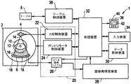
最初に、図1及び図2を参照すると、本発明の実施の形態を行なうために適当な代表的なCT画像形成システムが示される。システム1は、X線源4と、放射線検知器アレイ6と、患者支持構造体8と、患者キャビティ10とを有するガントリ2を含み、該X線源4及び放射線検知器アレイ6は、該患者キャビティ10により分離されるように、対向配設される。患者12が、患者支持構造体8の上に位置させられ、その後、該患者支持構造体は、患者キャビティ10に配設させられる。X線源4は、X線ビーム14が患者12を通過するように放射線検知器アレイの方向に照射する。X線ビーム14は、コリメート(図示せず)により平行光にされるのが好ましく、「画像形成平面」と呼ばれるデカルト座標系のX−Y平面内に位置するようにされる。患者12を通過し、該患者により減衰された後、減衰されたX線ビーム16は、放射線検知器アレイ6により受信される。放射線検知器アレイ6は、複数の検知器要素18を含み、各々の該検知器要素18が減衰されたX線ビーム16を受信し、該減衰されたX線ビーム16の強さに対応して電気信号を生成する。
Referring initially to FIGS. 1 and 2, a representative CT imaging system suitable for carrying out embodiments of the present invention is shown. The
さらに、X線源4及び放射線検知器アレイ6は、ガントリ2及び患者支持構造体8に対して回転するように配設され、該患者支持構造体が患者キャビティ10内に配設されたとき、該X線源4及び該放射線検知器アレイ6が該患者支持構造体8の周りを回転することを可能にする。次いでX線照射データが、走査の間にX線源4及び放射線検知器アレイ6を患者12の周りに回転させることにより得られる。X線源4及び放射線検知器アレイ6の回転及び作動は、CT画像形成システム1に関連する制御機構20により制御される。
Furthermore, the
より具体的には、制御機構20は、X線源4と通信するX線制御装置22と、ガントリモータ制御装置24と、放射線検知器アレイ6と通信するデータ獲得システム(DAS)26とを含む。X線制御装置22は、電力及びタイミング信号をX線源4に与え、ガントリモータ制御装置24は、該X線源4の回転速度及び角位置を制御し、放射線検知器アレイ6及びDAS26は、検知器要素18により生成された電気信号を受信し、該信号を後続する処理のためにデータ信号に変換する。このために、CT画像形成システム1はさらに、画像再構築装置28と、データ格納装置30と、処理装置32とを含み、該処理装置32は、さらに、該画像再構築装置28と、ガントリモータ制御装置24と、X線制御装置22と、データ格納装置30、並びに入力装置34と、出力装置36と通信する。最後に、CT画像形成システム1は、さらに、処理装置32及び患者支持構造体8と通信するテーブル制御装置38を特徴とし、該患者支持構造体8の位置を患者キャビティ10に対して制御するようにする。
More specifically, the
CT画像形成システム1の作動中、患者12は、患者支持構造体8上に位置させられ、その後、オペレータにより(処理装置32を介して)患者キャビティ10内に位置決めされる。次に、ガントリモータ制御装置24が処理装置32を介して作動させられ、それによりX線源4及び放射線検知器アレイ6が患者12に対して回転するようにする。X線制御装置22は、処理装置32を介して作動し、X線源4が平行光にされたX線ビーム14を放射線検知器アレイ6の方向に、すなわち患者12の方向に放射し、かつ照射するようにする。X線ビーム14は、X線検知器6アレイにより受信される減衰されたX線ビーム16を生成するように、患者12を通過する。
During operation of the
減衰されたX線ビーム16を受信すると、検知器要素18は、該減衰されたX線ビーム16の強さに対応して電気信号データを生成し、その後、この電気信号データをDAS26に通信する。DAS26は、次に、高速の画像再構築のために、電気信号データをデジタル信号に変換し、該デジタル信号及び該電気信号データの両方を画像再構築装置28に送る。この画像再構築情報を、次に、画像をデータ格納装置30に格納する処理装置32に通信し、出力装置36によりデジタル信号を画像として表示する。
Upon receipt of the
前述のように、最小の放射線量を患者に与えながらも尚、診断目的のために適当な画質を得られることが望ましい。患者を異なる線量において多数回の走査に曝す代わりに、低線量におけるCT画像のシミュレーションのための方法及びシステムが開示される。簡単に述べると、患者は、既存の診断治療法基準により処方される通常の方法で、一度だけ走査される。次に、患者の走査データを用いて、これにノイズデータを導入することにより、シミュレートされたより低い線量における画像を生成する。以下に述べるように、実施の一形態において、ノイズデータは生走査データと組み合わされ、別の実施の形態においては、該ノイズデータは画像データと組み合わされる。いずれの場合においても、画像データ及び関連するノイズデータの両方を用いて、より低い線量の走査により取得されたデータをシミュレートする画像(シミュレートされた画像データ)を再構築する。 As mentioned above, it is desirable to be able to obtain a suitable image quality for diagnostic purposes while still providing the patient with a minimal radiation dose. Instead of exposing the patient to multiple scans at different doses, a method and system for simulating CT images at low doses is disclosed. Briefly, the patient is scanned only once, in the usual way prescribed by existing diagnostic treatment criteria. The patient scan data is then used to generate an image at a simulated lower dose by introducing noise data into it. As described below, in one embodiment, noise data is combined with raw scan data, and in another embodiment, the noise data is combined with image data. In either case, both the image data and the associated noise data are used to reconstruct an image (simulated image data) that simulates the data acquired by the lower dose scan.
少なくとも2つの方法でより低い放射線量で患者の画像をシミュレートすることができる。より低い放射線量で患者の画像をシミュレートする1つの方法は、走査のために用いられたものよりも低い線量(mA値)をシミュレートするために、ポアソン分布を有する乱数発生器によりノイズを発生させ、このノイズを画像データに関連付けることを含む。このことは、有利にはより低い線量の走査により取得されたデータをシミュレートする画像(シミュレートされた画像データ)を再構築するために、画像データ及び関連するノイズデータを用いることを可能にする。 Patient images can be simulated at lower radiation doses in at least two ways. One method of simulating a patient image with a lower radiation dose is to use a random number generator with a Poisson distribution to simulate noise in order to simulate a lower dose (mA value) than that used for the scan. Generating and associating this noise with the image data. This advantageously allows the image data and associated noise data to be used to reconstruct an image (simulated image data) that simulates the data acquired by a lower dose scan. To do.
図3を参照すると、画像形成システム1を用いてより低い放射線量で患者の画像をシミュレートする方法100の第1の実施の形態が示されかつ説明される。方法100に関連する実施の形態は、走査のために用いられたものよりも低い線量(mA値)をシミュレートするために、ポアソン分布を有する乱数発生器によりノイズを発生させ、このノイズを画像データに関連付けることにより特徴づけられる。方法100は、ブロック102で開始され、ここで画像データ及びノイズデータの両方が取得される。画像データは画像形成システム1により取得することができ、該画像データは画像データのサンプル要素を含み、患者12に対応する。ノイズデータは、ポアソン分布を有する乱数発生器により取得することが好ましく、ノイズデータのサンプル要素を含むことが好ましい。しかしながら、ノイズデータを、所望の最終目的に適合するどのような信号発生装置及び/又は方法を用いて発生させてもよいことは理解されるであろう。ノイズデータ及び画像データが取得されると、次に、各画像データのサンプル要素に加えられるべきノイズデータの量が決められる。
With reference to FIG. 3, a first embodiment of a
シミュレートするように要求されるノイズ(すなわち、量子ノイズ)はフォトンの数の平方根の逆数に比例するため、各画像データのサンプル要素に加えられるべきノイズデータの量は、ポアソン分布に従う。従って、各画像データのサンプル要素は、検知したフォトンに利得係数乗算機による乗算を行なった数である。従って、各画像データのサンプル要素と関連付けられるべきポアソン分布ノイズ量を、以下の方程式を用いて求めることができ、 Since the noise required to simulate (ie, quantum noise) is proportional to the inverse of the square root of the number of photons, the amount of noise data to be added to each image data sample element follows a Poisson distribution. Therefore, the sample element of each image data is the number obtained by multiplying the detected photon by the gain coefficient multiplier. Therefore, the Poisson distribution noise amount to be associated with the sample element of each image data can be obtained using the following equation:

ここで、aは対応する画像データのサンプル要素と関連付けられるべきポアソン分布ノイズに適用される重み係数であり、βはその値がDASの利得及び画像処理特性に依存する縮尺係数であり、αは元の照射のmAに対するmA(線量)の低減係数(値<.1)であり、Dは該画像データのサンプル要素についてのDAS信号レベルである。 Where a is a weighting factor applied to Poisson distribution noise to be associated with the corresponding image data sample element, β is a scale factor whose value depends on the DAS gain and image processing characteristics, and α is The mA (dose) reduction factor (value <0.1) relative to the original illumination mA, and D is the DAS signal level for the sample elements of the image data.
各画像データのサンプル要素についてのポアソン分布ノイズが求められると、ブロック104に示されるように、ノイズデータを処理して、処理済ノイズデータが生成されるようにする。このことは、各画像データのサンプル要素についての乱数発生器からのポアソン分布ノイズに、対応するノイズの縮尺係数aを乗じることにより達成され、このようにして、処理済ノイズデータ要素を有する処理済ノイズデータが生成される。
Once the Poisson distribution noise for the sample elements of each image data is determined, the noise data is processed to generate processed noise data, as shown in
処理済ノイズデータが生成されると、ブロック106に示されるように、該処理済ノイズデータは、次に画像データと関連付けて画像前データを生成する。このことは、処理済ノイズデータ要素を対応する画像データのサンプル要素に加えることにより達成することができる。これが完了すると、次に、ブロック108に示されるように、画像前データが再構築されて、シミュレートされた画像データが生成される。このシミュレートされた画像データは、次に、元の患者の走査のmA管電流値にaを乗じたmA管電流値を用いて収集されたかのように、画像として表示することができる。
Once the processed noise data is generated, the processed noise data is then associated with the image data to generate pre-image data, as shown at
さらに、aを各照射についてのDの最大値を求めることにより近似することができ、βの値は、ポアソン分布ノイズに適用されるべきaの定数値が生成されるように予め定められる。さらに、βは適当な結果に適合するように経験的に求められることが好ましいが、βをさらに、所望の最終目的に適切などのような方法及び/又は装置を用いて求めてもよい。さらに、非量子ノイズも、画像データ内で観察される場合があり、信号レベルが十分に低いときに、フォトンのノイズと組み合わせてもよい。このような非量子ノイズの1つのソースは、DASにより生成された電子ノイズである。 Furthermore, a can be approximated by determining the maximum value of D for each irradiation, and the value of β is predetermined so that a constant value of a to be applied to the Poisson distribution noise is generated. Furthermore, although β is preferably determined empirically to suit an appropriate result, β may further be determined using methods and / or apparatus such as appropriate for the desired end purpose. Furthermore, non-quantum noise may also be observed in the image data and may be combined with photon noise when the signal level is sufficiently low. One source of such non-quantum noise is electronic noise generated by DAS.
非量子ノイズの場合、ポアソン分布ノイズPを付加的な縮尺係数Nnで乗じて、非量子ノイズに起因する結果に対処することができる。画像データ信号が十分に小さくて非量子ノイズが顕著である場合には、加えられたノイズの全部が、シミュレートされた画像データの量子ノイズ及び非量子ノイズを補償する程度にポアソン分布ノイズaが増加するように、縮尺係数Nnを定めるべきである。第1の実施の形態に従って、画像データに関連するノイズの全部が、以下の方程式を用いて求められ、
σa=aNnP (式2)
ここで、aは上の方程式(1)からもたらされた、対応する画像データのサンプル要素と関連するポアソン分布ノイズの量であり、Nnは非量子ノイズに起因するノイズの結果であり、Pは乱数発生器からのポアソン分布ノイズである。しかしながら、画像データ信号が十分に大きくて非量子ノイズが顕著でない(一般に、合計量子ノイズの振幅より10倍少ない)場合には、Nnの値は一致する、すなわち1となる。
In the case of non-quantum noise, the Poisson distribution noise P can be multiplied by an additional scale factor N n to address the results due to non-quantum noise. If the image data signal is sufficiently small and non-quantum noise is significant, the Poisson distribution noise a is such that all of the added noise compensates for the quantum noise and non-quantum noise of the simulated image data. The scale factor N n should be determined so as to increase. According to the first embodiment, all of the noise associated with the image data is determined using the following equation:
σ a = aN n P (Formula 2)
Where a is the amount of Poisson distribution noise associated with the sample element of the corresponding image data resulting from equation (1) above, N n is the result of the noise due to non-quantum noise, P is Poisson distribution noise from the random number generator. However, if the image data signal is sufficiently large and non-quantum noise is not significant (generally 10 times less than the amplitude of the total quantum noise), the values of N n match, i.e., 1.
図4を参照すると、画像形成システム1を用いてより低い放射線量で患者の画像をシミュレートする方法200の代替的な実施の形態が示されかつ説明される。ブロック202で開始され、画像データ及びノイズデータが初めに取得される。画像データは画像形成システム1により取得することが好ましく、該画像データは画像データのサンプル要素を含み、かつ患者12に対応する。この場合におけるノイズデータは、各蝶ネクタイ型フィルタについての複数のファントム被写体を走査すること及び画像形成システム1のkV設定により取得することが好ましい。従って、ノイズデータは、種々のファントムに対応する一組の10(最小)ノイズパターン画像と、種々の蝶ネクタイ型フィルタと、走査法と、種々のエミッタ管の電圧レベルとを含むことが好ましい。例えば、ノイズデータを抽出するために、2回のファントム被写体の走査が行なわれ、取得された画像は、該画像の各々についての生のノイズパターンを取得するために除去される。除去後に、ファントムの縁構造を含む如何なるピクセルも、ノイズパターンのランダム区域におけるものと等しい標準偏差を有するランダムな値で置き換えられる。
Referring to FIG. 4, an alternative embodiment of a
ノイズデータ(及び従ってノイズパターン画像)が取得されると、それらはデータ格納装置30に格納される。これらのノイズパターン画像は、用いられるべき様々な組み合わせが可能であるように予め決められ、十分な数の個々のノイズパターン画像を含み、従って、同じ組み合わせが過度に繰り返されることを避けるようにすることが好ましい。
Once the noise data (and thus the noise pattern image) is acquired, they are stored in the
ノイズデータが得られた後、ブロック204に示されるように、該ノイズデータが処理されて、処理済画像ノイズデータが生成される。このことは、格納されたノイズパターン画像を調査して、患者12の物理的な形状及び該患者12を走査するために用いられる走査法に最も適合するファントムの形状及び走査法に対応するノイズパターン画像を識別するようにすることにより達成される。患者に最も良く適合するノイズパターン画像と走査法とが求められると、所定の数の選択されたノイズパターン画像がランダムに選択されて、処理済ノイズデータが生成されるようになる。ノイズは、自乗の合計の平方根として加わるため、ノイズ画像は、選択されたノイズ画像の数の平方根の逆数だけ縮尺される(すなわち、乗算される)。
After the noise data is obtained, the noise data is processed to generate processed image noise data, as shown in
最後に、ブロック206に示されるように、処理済画像ノイズデータが患者の画像と関連付けられて、シミュレートされた画像が生成される。このことは、結果としてもたらされるノイズパターン画像を取得するために、ランダムに選択されたノイズパターン画像を加えることにより達成することができる。この結果としてもたらされるノイズパターン画像は補間されて、患者の画像のDFOVに適合するようになり、次に、所望の低線量画像をシミュレートするように求められた縮尺係数sにより縮尺される。縮尺係数sは、
Finally, as shown in
として、以下の方程式
s=σa/σp
を通して求めることができ、ここで、σaは元の患者の画像に加えられるべきノイズパターンの標準偏差であり、σpはランダムに選択され、補間されて合計されたノイズパターンの標準偏差であり、σfは線量が低減された患者の画像に望まれる標準偏差であり、σ0は元の患者の画像の標準偏差であり、αは元の画像の管電流に対するmA(線量)低減係数(値<1)である。
The following equation s = σ a / σ p
Where σ a is the standard deviation of the noise pattern to be added to the original patient image, and σ p is the standard deviation of the noise pattern chosen at random, interpolated and summed , Σ f is the standard deviation desired for the patient image with reduced dose, σ 0 is the standard deviation of the original patient image, and α is the mA (dose) reduction factor for the tube current of the original image ( Value <1).
さらに、元の画像のノイズ値σ0を選択されたファントムの画像のノイズパターンと等しくすることにより、σ0も見積ることができ、元の画像を取得するために用いられた走査法と、選択されたファントムの画像を取得するために用いられた走査法及び処理との間の差を補償するように調整された。さらに、垂直方向及び水平方向の向きにおけるピクセルデータを合計し、続いて、米国特許出願番号、代理人整理番号第122942号に記載されるようなノイズ予測方法を用いることにより、σ0を求めることができる。 Furthermore, by making the noise value σ 0 of the original image equal to the noise pattern of the selected phantom image, σ 0 can also be estimated, and the scanning method used to acquire the original image and the selection Adjusted to compensate for the difference between the scanning method and the process used to acquire the image of the phantom. Further, by summing the pixel data in the vertical and horizontal orientations, and subsequently determining σ 0 by using a noise prediction method as described in US Patent Application No., Attorney Docket No. 122942 Can do.
理解されるように、上述の実施の形態は、現在の診断治療法における処方のように、内科患者が、通常の方法で1度だけ走査を行なうことが可能となる利点をもつ。従って、患者は、通常の診断上の処方で受けていた以上には、研究のためにどのような付加的な放射線被爆も受けないようになる。患者のデータ(生データ及び/又は画像データ)は、さらに、シミュレートされたより低い線量で画像を生成するために用いられるため、研究者は、患者の線量被爆が、該患者の診断上の結果に影響があるかどうかを研究することができる。結果として、患者は、そのような臨床研究のために、異なる線量で何度も走査される必要がなくなる。 As will be appreciated, the above-described embodiments have the advantage that medical patients can scan only once in the usual way, as prescribing in current diagnostic treatments. Thus, patients will not receive any additional radiation exposure for research beyond what they have received on normal diagnostic prescriptions. Since patient data (raw data and / or image data) is further used to generate images with a simulated lower dose, the investigator can determine whether the patient's dose exposure is a diagnostic result of the patient. You can study whether there is an impact on As a result, the patient does not need to be scanned multiple times with different doses for such clinical studies.
さらに理解されるように、開示されたシミュレーション法は、一般に、磁気共鳴映像法(MRI)、超音波、X線、CT及び/又はPETのような所望の診断目的に適当な画像形成システムのいずれとも関連して適用することができる。さらに、図3及び/又は図4の方法の実施の形態を、コンピュータプログラムに対応して動作している処理装置32を通じて実施することができる。規定の機能及び所望の処理、並びに、そのための計算を実行するために(例えば、フーリエ解析アルゴリズムの実行、本明細書で規定される制御プロセスなど)、制御装置は、プロセッサ、コンピュータ、メモリ、記憶装置、レジスタ、タイミング、割り込み、通信インターフェース、及び入力/出力信号インターフェース、並びに、少なくとも1つの前述のものの組み合わせを含むが、これらに限られるものではない。例えば、制御装置は、通信インターフェースからのこのような信号の正確なサンプリング及び変換又は獲得を可能にするようにフィルタリングする信号入力信号を含むことができる。さらに、図3及び/又は図4の実施の形態を、処理装置32から離れて配置された制御装置により実施することが考慮される。
As will be further appreciated, the disclosed simulation methods generally include any imaging system suitable for the desired diagnostic purpose, such as magnetic resonance imaging (MRI), ultrasound, X-ray, CT and / or PET. And can be applied in conjunction with Furthermore, the embodiment of the method of FIGS. 3 and / or 4 can be implemented through the
上述のように、本発明は、コンピュータで実装されるプロセス及びこれらのプロセスを実行するための装置の形態で具現することができる。さらに本発明は、フレキシブルディスク、CD−ROM、ハードドライブ又は他のコンピュータ可読格納媒体のいずれかのような有形の媒体において具現される命令を含むコンピュータのプログラムコードの形態において具現化することができ、該コンピュータのプログラムコードがコンピュータにロードされ、該コンピュータにより実行されたときに、該コンピュータは、本発明を実行する装置となる。再プログラム可能な記憶装置(例えば、フラッシュメモリ)を有する既存のシステムを更新して、本発明を実装することができる。さらに、本発明は、例えば、格納媒体に格納されるか、コンピュータの中にロードされて及び/又は該コンピュータにより実行されるか、電気配線又はケーブル配線、光ファイバ、或いは電磁放射線を介したような特定の送信媒体を介して送信されるか、のいずれであってもコンピュータのプログラムの形態で具現化することができ、該コンピュータのプログラムコードがコンピュータの中にロードされ、該コンピュータにより実行されたときに、該コンピュータは、本発明を実行する装置となる。多目的マイクロプロセッサ上で実装されるとき、コンピュータのプログラムコードのセグメントは、特定の論理回路を生成するように該マイクロプロセッサを構成している。 As described above, the present invention can be embodied in the form of computer-implemented processes and apparatuses for performing these processes. Furthermore, the present invention can be embodied in the form of computer program code including instructions embodied in a tangible medium such as a flexible disk, CD-ROM, hard drive, or other computer-readable storage medium. When the program code of the computer is loaded into the computer and executed by the computer, the computer becomes an apparatus for executing the present invention. Existing systems with reprogrammable storage (eg, flash memory) can be updated to implement the present invention. Furthermore, the present invention may be stored in a storage medium, loaded into a computer and / or executed by the computer, such as via electrical or cabling, optical fiber, or electromagnetic radiation, for example. Can be realized in the form of a computer program, and the computer program code is loaded into the computer and executed by the computer. The computer becomes an apparatus for carrying out the present invention. When implemented on a general-purpose microprocessor, the computer program code segments configure the microprocessor to generate specific logic circuits.
本発明は、例示的な実施の形態に関して述べてきたが、本発明の技術的範囲から逸脱することなく、種々の変更を行なうことができ、その各要素に対して等価物で代替することができることは、当業者であれば理解されるであろう。さらに、本発明の技術的範囲から逸脱することなく、本発明の教示に対する特定の状況又は材料に適合するように、多くの変更を行なうことができる。従って、本発明は、本発明を実施することを企図した最良の形態として開示された特定の実施の形態に制限されるものではなく、添付の特許請求の範囲の技術的範囲内にあるすべての実施の形態を含むことが意図される。さらに、第1、第2等の用語の使用は、如何なる順番及び重要性をも示すものではなく、該第1、第2等の用語は、1つの要素を他のものと識別するために用いられるものである。 Although the present invention has been described with reference to exemplary embodiments, various modifications can be made without departing from the scope of the present invention, and equivalent elements may be substituted for each of the elements. Those skilled in the art will understand what can be done. In addition, many modifications may be made to adapt a particular situation or material to the teachings of the invention without departing from the scope of the invention. Accordingly, the invention is not limited to the specific embodiments disclosed as the best mode contemplated for carrying out the invention, but rather is within the scope of the appended claims. It is intended to include embodiments. Further, the use of terms such as first, second, etc. does not indicate any order or significance, and the first, second, etc. terms are used to distinguish one element from another. It is what
1 画像形成システム
2 ガントリ
4 X線源
6 放射線検知器アレイ
8 患者支持構造体
10 患者キャビティ
32 処理装置
DESCRIPTION OF
Claims (10)
画像データを実際の患者の画像から獲得し(102)、(202)、
ポワソン分布に従った、乱数発生器により、シミュレートされたノイズデータを発生させ(104)、(204)、
前記実際の患者の画像から獲得した前記画像データを前記シミュレートされたノイズデータと組み合わせて、予備的な画像データを生成し、
前記予備的な画像データを再構成して、シミュレートされた画像を生成し、
前記シミュレートされた画像データを前記シミュレートされたノイズデータと組み合わせて、シミュレートされた患者の画像を生成する、
段階を含み、
前記走査データからの個々の走査データサンプルの各々が、前記ポワソン分布乱数発生器から発生させられたランダムノイズ値と組み合わされ、前記ランダムノイズ値が、最初に重み係数を乗じられて、重み付けされたランダムノイズ値を生成し、
前記重み係数が、方程式
Acquiring image data from an actual patient image (102), (202);
Generate simulated noise data with a random number generator according to the Poisson distribution (104), (204),
Combining the image data acquired from the actual patient image with the simulated noise data to generate preliminary image data;
Reconstructing the preliminary image data to generate a simulated image;
Combining the simulated image data with the simulated noise data to generate a simulated patient image;
Including stages,
Each individual scan data sample from the scan data was combined with a random noise value generated from the Poisson distributed random number generator, and the random noise value was first multiplied by a weighting factor and weighted Generate random noise values,
The weighting factor is the equation
画像データを第1の放射線量で取られた実際のCT患者画像から獲得し(102)、(202)、
シミュレートされたノイズデータを発生させ(104)、(204)、
前記画像データを前記シミュレートされたノイズデータと組み合わせて、前記シミュレートされた患者の画像を生成する(108)、(206)、
段階を含み、
前記シミュレートされた画像が、前記第1の放射線量に対して低減された第2の放射線量で取られたCT患者画像をシミュレートする、
ことを特徴とする方法(100)、(200)。 A method (100), (200) for generating a simulated computed tomography (CT) patient image comprising:
Obtaining image data from actual CT patient images taken at a first radiation dose (102), (202);
Generating simulated noise data (104), (204),
Combining the image data with the simulated noise data to generate the simulated patient image (108), (206),
Including stages,
The simulated image simulates a CT patient image taken with a second radiation dose reduced with respect to the first radiation dose;
The method (100), (200) characterized by this.
前記画像前データを再構築して、シミュレートされた画像データを生成する、
段階をさらに含むことを特徴とする請求項2に記載の方法(100)。 Combining scan data from the actual patient image with the generated and simulated noise data to generate pre-image data;
Reconstructing the pre-image data to generate simulated image data;
The method (100) of claim 2, further comprising steps.
前記患者キャビティ(10)との通信を可能にするように、前記ガントリ(2)に対し移動可能に組み合わされた患者支持構造体(8)と、
画像データを実際の患者の画像から取得するための処理装置(32)と、
ポワソン分布に従った、乱数発生器により、シミュレートされたノイズデータを発生させるための手段と、
前記実際の患者の画像から獲得した前記画像データを前記シミュレートされたノイズデータと組み合わせて、予備的な画像データを生成するための手段と、
前記予備的な画像データを再構成して、シミュレートされた画像を生成する手段と、
前記シミュレートされた画像データを前記シミュレートされたノイズデータと組み合わせて、シミュレートされた患者の画像を生成する手段と、
が設けられ、
前記走査データからの個々の走査データサンプルの各々が、前記ポワソン分布乱数発生器から発生させられたランダムノイズ値と組み合わされ、前記ランダムノイズ値が、最初に重み係数を乗じられて、重み付けされたランダムノイズ値を生成し、
前記重み係数が、方程式
ことを特徴とする画像形成システム(1)。 A gantry (2) having an X-ray source (4) and a radiation detector (6) array and defining a patient cavity (10), wherein the X-ray source (4) and the radiation detector (6) array Rotatably coupled to the gantry (2) to be separated by the patient cavity (10);
A patient support structure (8) movably associated with the gantry (2) to allow communication with the patient cavity (10);
A processing device (32) for acquiring image data from an actual patient image;
Means for generating simulated noise data by a random number generator according to the Poisson distribution;
Means for combining the image data acquired from the actual patient image with the simulated noise data to generate preliminary image data;
Means for reconstructing the preliminary image data to generate a simulated image;
Means for combining the simulated image data with the simulated noise data to generate a simulated patient image;
Is provided,
Each individual scan data sample from the scan data was combined with a random noise value generated from the Poisson distributed random number generator, and the random noise value was first multiplied by a weighting factor and weighted Generate random noise values,
The weighting factor is the equation
An image forming system (1).
σa=aNnP
に従って求められる電子ノイズ縮尺係数を乗じられ、ここでNnは、非量子ノイズに起因する前記電子ノイズ縮尺係数であり、aは前記重み係数であり、Pは前記ポワソン分布乱数発生器から発生させられた前記ランダムノイズ値であり、σaは前記実際の患者の画像と組み合わされるべき前記発生させられ、シミュレートされたノイズデータの標準偏差である、ことを特徴とする請求項4に記載の画像形成システム(1)。 In addition to the weighting factor, each of the random noise values is further combined with individual scan data samples before the equation σa = aN n P
Is multiplied by the electronic noise scale factor determined according to: where N n is the electronic noise scale factor due to non-quantum noise, a is the weighting factor, and P is generated from the Poisson distributed random number generator. 5. The image of claim 4, wherein the random noise value is obtained and σa is a standard deviation of the generated and simulated noise data to be combined with the actual patient image. Forming system (1).
前記実際の患者の画像と組み合わされるべき少なくとも1つの個々のノイズパターン画像を選択するための手段と、 Means for selecting at least one individual noise pattern image to be combined with the actual patient image;
前記少なくとも1つの選択された個々のノイズパターン画像を前記実際の患者の画像と組み合わせ、これにより前記シミュレートされた患者の画像を生成するための手段と、 Means for combining the at least one selected individual noise pattern image with the actual patient image, thereby generating the simulated patient image;
をさらに含むことを特徴とする請求項4又は5に記載の画像形成システム(1)。The image forming system (1) according to claim 4 or 5, further comprising:
画像データを実際の患者の画像から獲得し、
ポワソン分布に従った、乱数発生器により、シミュレートされたノイズデータを発生させ、
前記実際の患者の画像から獲得した前記画像データを前記シミュレートされたノイズデータと組み合わせて、予備的な画像データを生成し、
前記予備的な画像データを再構成して、シミュレートされた画像を生成し、
前記シミュレートされた画像データを前記シミュレートされたノイズデータと組み合わせて、シミュレートされた患者の画像を生成する、
段階を含み、
前記走査データからの個々の走査データサンプルの各々が、前記ポワソン分布乱数発生器から発生させられたランダムノイズ値と組み合わされ、前記ランダムノイズ値が、最初に重み係数を乗じられて、重み付けされたランダムノイズ値を生成することを含み、
前記重み係数が、方程式
Acquiring image data from actual patient images,
Generate simulated noise data by random number generator according to Poisson distribution,
Combining the image data acquired from the actual patient image with the simulated noise data to generate preliminary image data;
Reconstructing the preliminary image data to generate a simulated image;
Combining the simulated image data with the simulated noise data to generate a simulated patient image;
Including stages,
Each individual scan data sample from the scan data was combined with a random noise value generated from the Poisson distributed random number generator, and the random noise value was first multiplied by a weighting factor and weighted Generating a random noise value,
The weighting factor is the equation
σa=aNnP
に従って求められる電子ノイズ縮尺係数で乗じられ、ここでNnは、非量子ノイズに起因する前記電子ノイズ縮尺係数であり、aは前記重み係数であり、Pは前記ポワソン分布乱数発生器から発生させられた前記ランダムノイズ値であり、σaは前記実際の患者の画像と組み合わされるべき前記発生させられ、シミュレートされたノイズデータの標準偏差である、ことを特徴とする請求項8に記載の格納媒体。 In addition to the weighting factor, each of the random noise values is further combined with individual scan data samples before the equation σa = aN n P
Is multiplied by an electronic noise scale factor determined according to: where N n is the electronic noise scale factor due to non-quantum noise, a is the weighting factor, and P is generated from the Poisson distributed random number generator. 9. The storage of claim 8, wherein the stored random noise value and [sigma] a is a standard deviation of the generated and simulated noise data to be combined with the actual patient image. Medium.
前記実際の患者の画像と組み合わされるべき少なくとも1つの個々のノイズパターン画像を選択し、 Selecting at least one individual noise pattern image to be combined with the actual patient image;
前記少なくとも1つの選択された個々のノイズパターン画像を前記実際の患者の画像と組み合わせて、これにより前記シミュレートされた患者の画像を生成する、 Combining the at least one selected individual noise pattern image with the actual patient image, thereby generating the simulated patient image;
指示をさらに含むことを特徴とする請求項8または9に記載の格納媒体。The storage medium according to claim 8, further comprising instructions.
Applications Claiming Priority (1)
| Application Number | Priority Date | Filing Date | Title |
|---|---|---|---|
| US10/064,586 US6829323B2 (en) | 2002-07-29 | 2002-07-29 | Method and system for low dose image simulation for imaging systems |
Publications (3)
| Publication Number | Publication Date |
|---|---|
| JP2004057831A JP2004057831A (en) | 2004-02-26 |
| JP2004057831A5 JP2004057831A5 (en) | 2008-10-09 |
| JP4344191B2 true JP4344191B2 (en) | 2009-10-14 |
Family
ID=30769096
Family Applications (1)
| Application Number | Title | Priority Date | Filing Date |
|---|---|---|---|
| JP2003280544A Expired - Fee Related JP4344191B2 (en) | 2002-07-29 | 2003-07-28 | Method and system for low-dose image simulation of an imaging system |
Country Status (3)
| Country | Link |
|---|---|
| US (1) | US6829323B2 (en) |
| EP (1) | EP1393682B1 (en) |
| JP (1) | JP4344191B2 (en) |
Families Citing this family (25)
| Publication number | Priority date | Publication date | Assignee | Title |
|---|---|---|---|---|
| US20030206662A1 (en) * | 2002-05-03 | 2003-11-06 | Avinash Gopal B. | Method and apparatus for improving perceived digital image quality |
| DE102004046441B8 (en) * | 2004-09-24 | 2006-07-06 | Siemens Ag | Method for image reproduction, in particular in medical single or continuous shooting |
| DE102005001681B4 (en) * | 2005-01-13 | 2007-10-11 | Siemens Ag | Method for determining acquisition parameters for a medical tomography device and associated device |
| JP2006212308A (en) * | 2005-02-07 | 2006-08-17 | Ge Medical Systems Global Technology Co Llc | Tomographic radiography device, simulation method for radiographic image and image simulation device |
| JP4174487B2 (en) * | 2005-03-24 | 2008-10-29 | アドバンスド・マスク・インスペクション・テクノロジー株式会社 | Image correction method |
| JP2007014755A (en) * | 2005-06-06 | 2007-01-25 | Toshiba Corp | Medical image displaying device, medical image generating program and x-ray computerized tomographic device |
| EP1731100B9 (en) * | 2005-06-06 | 2013-01-23 | Kabushiki Kaisha Toshiba | Medical image display apparatus and medical image display system |
| WO2007114470A1 (en) * | 2006-04-04 | 2007-10-11 | Hitachi Medical Corporation | X-ray ct scan simulator device, x-ray ct device and x-ray ct scan simulator program |
| US20080118128A1 (en) * | 2006-11-21 | 2008-05-22 | Thomas Louis Toth | Methods and systems for enhanced accuracy image noise addition |
| JP5006732B2 (en) * | 2007-08-09 | 2012-08-22 | キヤノン株式会社 | Radiation imaging apparatus and control method thereof |
| DE102007046941B4 (en) * | 2007-09-28 | 2017-12-28 | Siemens Healthcare Gmbh | Method for displaying medical images and X-ray diagnostic device |
| US8270560B2 (en) * | 2008-02-25 | 2012-09-18 | Hitachi Medical Corporation | X-ray CT scan simulator and X-ray CT apparatus |
| GB0906461D0 (en) * | 2009-04-15 | 2009-05-20 | Siemens Medical Solutions | Partial volume correction via smoothing at viewer |
| US8891849B2 (en) * | 2009-07-17 | 2014-11-18 | Tip Imaging, Llc | Extended low contrast detectability for radiographic imaging systems |
| US8219517B2 (en) * | 2009-07-27 | 2012-07-10 | Microsoft Corporation | Multi-class Poisson disk sampling |
| JP5543194B2 (en) * | 2009-12-24 | 2014-07-09 | キヤノン株式会社 | Information processing apparatus, processing method, and program |
| WO2011083388A2 (en) * | 2010-01-06 | 2011-07-14 | Koninklijke Philips Electronics N.V. | Method for simulating reduction of acquisition dosage of an x-ray system, computer system and x-ray system |
| GB2484355B (en) * | 2010-11-18 | 2012-09-26 | Masar Scient Ltd Company | System and method |
| JP2013017511A (en) * | 2011-07-07 | 2013-01-31 | Toshiba Corp | Image processing apparatus and method and x-ray diagnosis apparatus |
| US9311681B2 (en) | 2012-01-24 | 2016-04-12 | Facebook, Inc. | Claiming conversations between users and non-users of a social networking system |
| US20130202079A1 (en) | 2012-02-07 | 2013-08-08 | Lifeng Yu | System and Method for Controlling Radiation Dose for Radiological Applications |
| US9331681B2 (en) * | 2013-11-05 | 2016-05-03 | STMicroelectronics International N.V | System and method for gaussian random noise generation |
| CN104116518B (en) * | 2014-06-23 | 2016-06-01 | 沈阳东软医疗系统有限公司 | A kind of injectivity optimizing scan method and device |
| JP2017086762A (en) * | 2015-11-16 | 2017-05-25 | キヤノン株式会社 | Image processing device |
| CN112690810B (en) * | 2020-12-22 | 2023-08-15 | 上海联影医疗科技股份有限公司 | Scanning method and medical scanning system based on priori information |
Family Cites Families (1)
| Publication number | Priority date | Publication date | Assignee | Title |
|---|---|---|---|---|
| US6272200B1 (en) * | 1999-07-28 | 2001-08-07 | Arch Development Corporation | Fourier and spline-based reconstruction of helical CT images |
-
2002
- 2002-07-29 US US10/064,586 patent/US6829323B2/en not_active Expired - Fee Related
-
2003
- 2003-07-18 EP EP03254491A patent/EP1393682B1/en not_active Expired - Fee Related
- 2003-07-28 JP JP2003280544A patent/JP4344191B2/en not_active Expired - Fee Related
Also Published As
| Publication number | Publication date |
|---|---|
| US6829323B2 (en) | 2004-12-07 |
| EP1393682A3 (en) | 2007-05-30 |
| EP1393682A2 (en) | 2004-03-03 |
| EP1393682B1 (en) | 2012-09-12 |
| US20040017880A1 (en) | 2004-01-29 |
| JP2004057831A (en) | 2004-02-26 |
Similar Documents
| Publication | Publication Date | Title |
|---|---|---|
| JP4344191B2 (en) | Method and system for low-dose image simulation of an imaging system | |
| JP4542319B2 (en) | Plaque feature evaluation method, system and computer product | |
| EP1526808B1 (en) | Systems for detecting components of plaque | |
| JP5703014B2 (en) | Dual energy imaging with reduced sampling rate | |
| US9070181B2 (en) | System and method for extracting features of interest from an image | |
| JP4361778B2 (en) | Method and apparatus for forming computed tomography (CT) scout images | |
| JP5336364B2 (en) | Gain calibration of X-ray detector according to the ratio of scattered radiation | |
| JP4402435B2 (en) | Method and apparatus for visualization of soft tissue space | |
| JP4937927B2 (en) | X-ray CT apparatus and imaging condition determination method in X-ray CT apparatus | |
| US20130202079A1 (en) | System and Method for Controlling Radiation Dose for Radiological Applications | |
| US20040101090A1 (en) | Methods and apparatus for acquiring perfusion data | |
| JP4468352B2 (en) | Reconstruction of local patient dose in computed tomography | |
| CN109770933A (en) | The system and method for improving picture quality by three-dimensional localization | |
| US7822253B2 (en) | Methods and apparatus for BMD measuring | |
| WO2006090321A1 (en) | Determination of the coverage of a ct scan | |
| US20030083561A1 (en) | Method and apparatus of determining and displaying a helical artifact index | |
| US11288775B2 (en) | Methods and systems for parametric noise modulation in x-ray imaging | |
| EP3404618B1 (en) | Poly-energetic reconstruction method for metal artifacts reduction | |
| JP2005095397A (en) | Method of correcting scattered x-ray component, program therefor, and x-ray ct system | |
| US20230145920A1 (en) | Systems and methods for motion detection in medical images | |
| US20050018889A1 (en) | Systems and methods for filtering images |
Legal Events
| Date | Code | Title | Description |
|---|---|---|---|
| A521 | Request for written amendment filed |
Free format text: JAPANESE INTERMEDIATE CODE: A523 Effective date: 20060725 |
|
| A621 | Written request for application examination |
Free format text: JAPANESE INTERMEDIATE CODE: A621 Effective date: 20060725 |
|
| A521 | Request for written amendment filed |
Free format text: JAPANESE INTERMEDIATE CODE: A523 Effective date: 20080730 |
|
| A521 | Request for written amendment filed |
Free format text: JAPANESE INTERMEDIATE CODE: A523 Effective date: 20080821 |
|
| A131 | Notification of reasons for refusal |
Free format text: JAPANESE INTERMEDIATE CODE: A131 Effective date: 20090331 |
|
| A521 | Request for written amendment filed |
Free format text: JAPANESE INTERMEDIATE CODE: A523 Effective date: 20090527 |
|
| RD02 | Notification of acceptance of power of attorney |
Free format text: JAPANESE INTERMEDIATE CODE: A7422 Effective date: 20090527 |
|
| RD04 | Notification of resignation of power of attorney |
Free format text: JAPANESE INTERMEDIATE CODE: A7424 Effective date: 20090527 |
|
| TRDD | Decision of grant or rejection written | ||
| A01 | Written decision to grant a patent or to grant a registration (utility model) |
Free format text: JAPANESE INTERMEDIATE CODE: A01 Effective date: 20090616 |
|
| A01 | Written decision to grant a patent or to grant a registration (utility model) |
Free format text: JAPANESE INTERMEDIATE CODE: A01 |
|
| A61 | First payment of annual fees (during grant procedure) |
Free format text: JAPANESE INTERMEDIATE CODE: A61 Effective date: 20090710 |
|
| FPAY | Renewal fee payment (event date is renewal date of database) |
Free format text: PAYMENT UNTIL: 20120717 Year of fee payment: 3 |
|
| R150 | Certificate of patent or registration of utility model |
Ref document number: 4344191 Country of ref document: JP Free format text: JAPANESE INTERMEDIATE CODE: R150 Free format text: JAPANESE INTERMEDIATE CODE: R150 |
|
| FPAY | Renewal fee payment (event date is renewal date of database) |
Free format text: PAYMENT UNTIL: 20120717 Year of fee payment: 3 |
|
| FPAY | Renewal fee payment (event date is renewal date of database) |
Free format text: PAYMENT UNTIL: 20130717 Year of fee payment: 4 |
|
| R250 | Receipt of annual fees |
Free format text: JAPANESE INTERMEDIATE CODE: R250 |
|
| R250 | Receipt of annual fees |
Free format text: JAPANESE INTERMEDIATE CODE: R250 |
|
| R250 | Receipt of annual fees |
Free format text: JAPANESE INTERMEDIATE CODE: R250 |
|
| R250 | Receipt of annual fees |
Free format text: JAPANESE INTERMEDIATE CODE: R250 |
|
| R250 | Receipt of annual fees |
Free format text: JAPANESE INTERMEDIATE CODE: R250 |
|
| R250 | Receipt of annual fees |
Free format text: JAPANESE INTERMEDIATE CODE: R250 |
|
| R250 | Receipt of annual fees |
Free format text: JAPANESE INTERMEDIATE CODE: R250 |
|
| R250 | Receipt of annual fees |
Free format text: JAPANESE INTERMEDIATE CODE: R250 |
|
| LAPS | Cancellation because of no payment of annual fees |