JP4831442B2 - Collision determination device - Google Patents
Collision determination device Download PDFInfo
- Publication number
- JP4831442B2 JP4831442B2 JP2010543643A JP2010543643A JP4831442B2 JP 4831442 B2 JP4831442 B2 JP 4831442B2 JP 2010543643 A JP2010543643 A JP 2010543643A JP 2010543643 A JP2010543643 A JP 2010543643A JP 4831442 B2 JP4831442 B2 JP 4831442B2
- Authority
- JP
- Japan
- Prior art keywords
- vehicle
- collision
- curvature radius
- collision determination
- condition
- Prior art date
- Legal status (The legal status is an assumption and is not a legal conclusion. Google has not performed a legal analysis and makes no representation as to the accuracy of the status listed.)
- Active
Links
Images


Classifications
-
- G—PHYSICS
- G08—SIGNALLING
- G08G—TRAFFIC CONTROL SYSTEMS
- G08G1/00—Traffic control systems for road vehicles
- G08G1/16—Anti-collision systems
- G08G1/166—Anti-collision systems for active traffic, e.g. moving vehicles, pedestrians, bikes
Landscapes
- Physics & Mathematics (AREA)
- General Physics & Mathematics (AREA)
- Traffic Control Systems (AREA)
- Radar Systems Or Details Thereof (AREA)
Description
本発明は、例えば、車両に搭載され、他の車両と衝突する可能性の有無を判定する衝突判定装置に関する。 The present invention relates to, for example, a collision determination device that is mounted on a vehicle and determines whether or not there is a possibility of collision with another vehicle.
従来、他の車両と衝突する可能性の有無を判定する種々の装置、方法等が提案されている。例えば、以下に述べるような衝突予知方法が開示されている(特許文献1参照)。すなわち、まず、対象車両と自車両との相対位置(相対距離、方位角)と相対速度を求めて記憶し、所定の予測時間経過後の対象車両の推定移動方向に平行で自車両を通る平行領域を設定し、対象車両の幅方向のエッジと相対距離に基づいて対象車両の推定存在域を求める。そして、所定の予測時間後の対象車両の予測位置が自車両から所定の閾距離の範囲内にあるか否かを判断し(=危険レンジによる衝突予知)、予測位置が閾距離の範囲内にある場合、平行領域と推定存在域との相対的な位置関係に基づいて、対象車両との衝突可能性を判断する(=ラップ可能性による衝突予知)。
しかしながら、特許文献1に記載の衝突予知方法では、対象車両の予測時間経過後の移動方向ベクトルを考慮して求めたラップ率に基づいて衝突可能性が判断されるため、カーブ路等では、正確な判断がなされない虞がある。すなわち、カーブ路等において、自車両及び他の車両(例えば、対向車両)が進行方向を変更中である場合には、対向車両の移動方向ベクトルは、予測時間に応じてその向きが変化するため、予測時間が適正ではないと、ラップ率を正確に求めることができないのである。
However, in the collision prediction method described in
具体的には、図13に示すような場合には、シートベルト、ヘッドレスト等の乗員保護装置等を不要作動させる虞がある。図13は、カーブ路における自車両VC1及び対向車両VC2の移動方向ベクトルQ1、Q2の一例を示す平面図である。図13に示すように、自車両VC1及び対向車両VC2は通常の走行状態(=衝突の可能性があるとは言えない走行状態)であるにも拘わらず、対向車両VC2の移動方向ベクトルQ2が自車両VC1に向いているため、特許文献1に記載の衝突予知方法によれば、乗員保護装置等を不要作動させる虞があるのである。
Specifically, in the case as shown in FIG. 13, there is a possibility that an occupant protection device such as a seat belt or a headrest is unnecessarily operated. FIG. 13 is a plan view showing an example of the movement direction vectors Q1 and Q2 of the host vehicle VC1 and the oncoming vehicle VC2 on a curved road. As shown in FIG. 13, although the host vehicle VC1 and the oncoming vehicle VC2 are in a normal driving state (= a driving state in which there is no possibility of a collision), the moving direction vector Q2 of the oncoming vehicle VC2 is Since it is suitable for the host vehicle VC1, according to the collision prediction method described in
本発明は、上記事情に鑑みてなされたものであって、乗員保護装置等の不要作動を抑制することの可能な衝突判定装置を提供することにある。 This invention is made in view of the said situation, Comprising: It is providing the collision determination apparatus which can suppress unnecessary operation | movement of a passenger | crew protection apparatus.
上記目的を達成するために、本発明は、以下の特徴を有している。本発明の第1の局面は、車両に搭載され、他の車両と衝突する可能性の有無を判定する衝突判定装置であって、可能性判定手段、進行方向判定手段、及び、条件変更手段を備える。前記可能性判定手段は、前記他の車両と衝突する可能性があるか否かを判定する。また、前記進行方向判定手段は、自車両及び前記他の車両の少なくとも一方が、進行方向を変更中であるか否か、を判定する。更に、前記条件変更手段は、前記進行方向判定手段によって進行方向を変更中であると判定された場合に、前記可能性推定手段において衝突する可能性があると判定する条件である衝突判定条件を厳しくするべく変更する。 In order to achieve the above object, the present invention has the following features. A first aspect of the present invention is a collision determination device that is mounted on a vehicle and determines whether or not there is a possibility of a collision with another vehicle. The collision determination device includes a possibility determination unit, a traveling direction determination unit, and a condition change unit. Prepare. The possibility determination means determines whether or not there is a possibility of collision with the other vehicle. Further, the traveling direction determination means determines whether or not at least one of the own vehicle and the other vehicle is changing the traveling direction. Further, the condition changing means determines a collision determination condition which is a condition for determining that there is a possibility of collision in the possibility estimating means when the traveling direction determining means determines that the traveling direction is being changed. Change to be stricter.
なお、本発明において、「衝突判定条件を厳しくする」とは、「衝突判定条件」を衝突する可能性があると判定され難くすることを意味している。換言すれば、「衝突判定条件を厳しくする」とは、「衝突判定条件」によって規定される衝突が発生する可能性があると判定される範囲(又は、領域等)を狭くすることを意味している。 In the present invention, “to make the collision determination condition strict” means to make it difficult to determine that the “collision determination condition” is likely to collide. In other words, “to make the collision determination condition strict” means to narrow the range (or area, etc.) where it is determined that the collision specified by the “collision determination condition” may occur. ing.
本発明の第2の局面は、上記第1の局面において、前記他の車両の代表点が、今後進行する軌跡である進行軌跡を推定する軌跡推定手段、を備える。また、前記可能性推定手段が、前記軌跡推定手段によって推定された進行軌跡上を、予め設定された車幅及び車長を有する前記他の車両が移動する場合に、前記他の車両が自車両と交差するか否かに応じて、前記他の車両と衝突する可能性があるか否かを判定する。 According to a second aspect of the present invention, there is provided a trajectory estimating means for estimating a travel trajectory in which the representative point of the other vehicle travels in the future in the first aspect. Further, when the other vehicle having a preset vehicle width and vehicle length moves on the traveling locus estimated by the locus estimating means, the possibility estimating means determines that the other vehicle is the own vehicle. It is determined whether or not there is a possibility of a collision with the other vehicle.
本発明の第3の局面は、上記第2の局面において、前記条件変更手段が、前記他の車両の車幅及び車長の少なくとも一方を小さくすることによって、前記衝突判定条件を厳しくするべく変更する。 According to a third aspect of the present invention, in the second aspect, the condition changing unit is changed to make the collision determination condition stricter by reducing at least one of a vehicle width and a vehicle length of the other vehicle. To do.
本発明の第4の局面は、上記第2の局面において、レーダを介して前記他の車両の位置を検出する物体検出手段、を備える。また、前記他の車両の代表点が、前記レーダによって前記他の車両が捕捉された捕捉点である。 According to a fourth aspect of the present invention, there is provided the object detecting means for detecting the position of the other vehicle via a radar in the second aspect. The representative point of the other vehicle is a capture point where the other vehicle is captured by the radar.
本発明の第5の局面は、上記第1の局面において、自車両の位置する道路の曲率半径を求める曲率半径算出手段、を備える。また、前記進行方向判定手段が、前記曲率半径算出手段によって求められた曲率半径に基づいて、自車両が進行方向を変更中であるか否か、を判定する。 According to a fifth aspect of the present invention, there is provided a curvature radius calculating means for obtaining a curvature radius of a road on which the host vehicle is located in the first aspect. Further, the traveling direction determination unit determines whether or not the host vehicle is changing the traveling direction based on the curvature radius obtained by the curvature radius calculation unit.
本発明の第6の局面は、上記第5の局面において、前記進行方向判定手段が、前記曲率半径算出手段によって求められた曲率半径が予め設定された閾値半径以下である場合に、自車両が進行方向を変更中であると判定する。 According to a sixth aspect of the present invention, in the fifth aspect, when the traveling direction determination unit has the curvature radius obtained by the curvature radius calculation unit equal to or less than a preset threshold radius, It is determined that the traveling direction is being changed.
本発明の第7の局面は、上記第5の局面において、前記曲率半径算出手段が、車速をヨーレートで除することによって前記曲率半径を求める。 According to a seventh aspect of the present invention, in the fifth aspect, the curvature radius calculation means obtains the curvature radius by dividing the vehicle speed by the yaw rate.
本発明の第8の局面は、上記第1の局面において、自車両の位置する道路の曲率半径を求める曲率半径算出手段、を備える。また、前記条件変更手段が、前記曲率半径算出手段によって求められた曲率半径に基づいて、前記衝突判定条件を変更する。 According to an eighth aspect of the present invention, there is provided a curvature radius calculating means for obtaining a curvature radius of a road on which the host vehicle is located in the first aspect. Further, the condition changing unit changes the collision determination condition based on the curvature radius obtained by the curvature radius calculating unit.
本発明の第9の局面は、上記第8の局面において、前記曲率半径算出手段が、車速をヨーレートで除することによって前記曲率半径を求める。 According to a ninth aspect of the present invention, in the eighth aspect, the curvature radius calculation unit obtains the curvature radius by dividing a vehicle speed by a yaw rate.
本発明の第10の局面は、上記第2の局面において、自車両の位置する道路の曲率半径を求める曲率半径算出手段、を備える。また、前記条件変更手段が、前記曲率半径算出手段によって求められた曲率半径に基づいて、前記他の車両の車幅及び車長の少なくとも一方を変更することによって前記衝突判定条件を変更する。 According to a tenth aspect of the present invention, there is provided a curvature radius calculating means for obtaining a curvature radius of a road where the host vehicle is located in the second aspect. The condition changing means changes the collision determination condition by changing at least one of the vehicle width and the vehicle length of the other vehicle based on the curvature radius obtained by the curvature radius calculating means.
本発明の第11の局面は、上記第10の局面において、前記条件変更手段が、前記曲率半径算出手段によって求められた曲率半径に略比例して、前記他の車両の車長を変更することによって前記衝突判定条件を変更する。 In an eleventh aspect of the present invention, in the tenth aspect, the condition changing means changes the vehicle length of the other vehicle substantially in proportion to the curvature radius obtained by the curvature radius calculation means. To change the collision determination condition.
本発明の第12の局面は、上記第1の局面において、前記進行方向判定手段が、前記他の車両の過去における進行軌跡に基づいて、前記他の車両が進行方向を変更中であるか否か、を判定する。 In a twelfth aspect of the present invention, in the first aspect, the traveling direction determination unit determines whether the traveling direction of the other vehicle is changing based on a traveling locus of the other vehicle in the past. To determine.
上記第1の局面によれば、可能性判定手段によって、他の車両と衝突する可能性があるか否かが判定される。また、自車両及び前記他の車両の少なくとも一方が、進行方向を変更中であるか否かが判定される。更に、進行方向を変更中であると判定された場合に、前記可能性推定手段において衝突する可能性があると判定する条件である衝突判定条件が厳しくするべく変更される。従って、乗員保護装置等の不要作動を抑制することができる。 According to the first aspect, the possibility determination means determines whether or not there is a possibility of collision with another vehicle. Further, it is determined whether or not at least one of the own vehicle and the other vehicle is changing the traveling direction. Furthermore, when it is determined that the traveling direction is being changed, the collision determination condition, which is a condition for determining that there is a possibility of collision in the possibility estimation means, is changed to be strict. Therefore, unnecessary operations of the occupant protection device and the like can be suppressed.
すなわち、自車両及び他の車両の少なくとも一方が、進行方向を変更中であると判定された場合には、自車両及び他の車両の少なくとも一方がカーブ路を走行中であると推定される。そこで、この場合には、図13を用いて上述のように、乗員保護装置等が不要作動される虞がある。しかしながら、衝突する可能性があると判定する条件である衝突判定条件が厳しくするべく変更されるため、乗員保護装置等の不要作動を抑制することができるのである。 That is, when it is determined that at least one of the host vehicle and the other vehicle is changing the traveling direction, it is estimated that at least one of the host vehicle and the other vehicle is traveling on the curved road. Therefore, in this case, as described above with reference to FIG. However, since the collision determination condition, which is a condition for determining that there is a possibility of a collision, is changed to be strict, unnecessary operations of the occupant protection device and the like can be suppressed.
上記第2の局面によれば、前記他の車両の代表点が、今後進行する軌跡である進行軌跡が推定される。そして、推定された進行軌跡上を、予め設定された車幅及び車長を有する前記他の車両が移動する場合に、前記他の車両が自車両と交差するか否かに応じて、前記他の車両と衝突する可能性があるか否かが判定されるため、衝突する可能性があるか否かを正確に判定することができる。 According to the second aspect, a travel locus that is a locus where the representative point of the other vehicle proceeds in the future is estimated. Then, when the other vehicle having a preset vehicle width and vehicle length moves on the estimated traveling locus, the other vehicle depends on whether or not the other vehicle intersects with the own vehicle. Since it is determined whether or not there is a possibility of collision with another vehicle, it can be accurately determined whether or not there is a possibility of collision.
上記第3の局面によれば、前記他の車両の車幅及び車長の少なくとも一方を小さくすることによって、前記衝突判定条件が厳しくするべく変更されるため、簡素な方法で適正に前記衝突判定条件を厳しくするべく変更することができる。 According to the third aspect, since the collision determination condition is changed to be stricter by reducing at least one of the vehicle width and the vehicle length of the other vehicle, the collision determination is appropriately performed by a simple method. It can be changed to tighten the conditions.
上記第4の局面によれば、レーダを介して前記他の車両の位置が検出される。そして、前記他の車両の代表点が、前記レーダによって前記他の車両が捕捉された捕捉点であるため、前記他の車両の代表点を適正に設定することができる。 According to the fourth aspect, the position of the other vehicle is detected via the radar. Since the representative point of the other vehicle is a capture point where the other vehicle is captured by the radar, the representative point of the other vehicle can be set appropriately.
すなわち、前記他の車両の代表点が、前記レーダによって前記他の車両が捕捉された捕捉点であるため、前記他の車両に関する過去の捕捉点の前記レーダによる検出結果(相対位置、相対速度)に基づいて、前記他の車両が今後進行する軌跡である進行軌跡を容易に推定することができるのである。 That is, since the representative point of the other vehicle is a capture point at which the other vehicle is captured by the radar, the detection result (relative position, relative speed) of the past capture point related to the other vehicle by the radar. Based on the above, it is possible to easily estimate a travel locus that is a locus on which the other vehicle will proceed in the future.
上記第5の局面によれば、自車両の位置する道路の曲率半径が求められる。また、求められた曲率半径に基づいて、自車両が進行方向を変更中であるか否かが判定されるため、自車両が進行方向を変更中であるか否か、を適正に判定することができる。 According to the fifth aspect, the radius of curvature of the road on which the host vehicle is located is obtained. Moreover, since it is determined whether or not the own vehicle is changing the traveling direction based on the calculated curvature radius, it is properly determined whether or not the own vehicle is changing the traveling direction. Can do.
上記第6の局面によれば、求められた曲率半径が予め設定された閾値半径以下である場合に、自車両が進行方向を変更中であると判定されるため、自車両が進行方向を変更中であるか否か、を容易に判定することができる。 According to the sixth aspect, when the calculated curvature radius is equal to or smaller than a preset threshold radius, it is determined that the own vehicle is changing the traveling direction, so the own vehicle changes the traveling direction. It can be easily determined whether or not it is in the middle.
上記第7の局面によれば、車速をヨーレートで除することによって前記曲率半径が求められるため、前記曲率半径を容易に求めることができる。 According to the seventh aspect, since the radius of curvature is obtained by dividing the vehicle speed by the yaw rate, the radius of curvature can be easily obtained.
上記第8の局面によれば、自車両の位置する道路の曲率半径が求められる。また、求められた曲率半径に基づいて、前記衝突判定条件が変更されるため、前記衝突判定条件を適正に変更することができる。 According to the eighth aspect, the radius of curvature of the road on which the host vehicle is located is obtained. Moreover, since the said collision determination conditions are changed based on the calculated | required curvature radius, the said collision determination conditions can be changed appropriately.
すなわち、道路の曲率半径が小さい程、前記他の車両が自車両に接近した状態で、前記他の車両の移動方向ベクトルが自車両に向くため、乗員保護装置等が不要作動される虞が高くなる。そこで、求められた曲率半径に基づいて、前記衝突判定条件が変更される(例えば、曲率半径が小さい程、前記衝突判定条件を厳しくするべく変更される)ため、前記衝突判定条件を適正に変更することができるのである。 In other words, the smaller the radius of curvature of the road, the higher the possibility that the occupant protection device or the like will be operated unnecessarily because the moving direction vector of the other vehicle is directed toward the own vehicle when the other vehicle is closer to the own vehicle. Become. Therefore, the collision determination condition is changed based on the calculated curvature radius (for example, the collision determination condition is changed to be stricter as the curvature radius is smaller), so the collision determination condition is appropriately changed. It can be done.
上記第9の局面によれば、車速をヨーレートで除することによって前記曲率半径が求められるため、前記曲率半径を容易に求めることができる。 According to the ninth aspect, since the curvature radius is obtained by dividing the vehicle speed by the yaw rate, the curvature radius can be easily obtained.
上記第10の局面によれば、自車両の位置する道路の曲率半径が求められる。また、求められた曲率半径に基づいて、前記他の車両の車幅及び車長の少なくとも一方を変更することによって前記衝突判定条件が変更される。従って、簡素な方法で適正に前記衝突判定条件を厳しくするべく変更することができる。 According to the tenth aspect, the radius of curvature of the road on which the host vehicle is located is obtained. Further, the collision determination condition is changed by changing at least one of the vehicle width and the vehicle length of the other vehicle based on the calculated curvature radius. Therefore, it is possible to change the collision determination condition appropriately and strictly by a simple method.
上記第11の局面によれば、求められた曲率半径に略比例して、前記他の車両の車長を変更することによって前記衝突判定条件が変更される。従って、更に簡素な方法で適正に前記衝突判定条件を厳しくするべく変更することができる。 According to the eleventh aspect, the collision determination condition is changed by changing the vehicle length of the other vehicle substantially in proportion to the calculated radius of curvature. Therefore, it is possible to change the collision determination condition appropriately and strictly by a simpler method.
上記第12の局面によれば、前記他の車両の過去における進行軌跡に基づいて、前記他の車両が進行方向を変更中であるか否かが判定されるため、前記他の車両が進行方向を変更中であるか否か、を適正に判定することができる。 According to the twelfth aspect, since it is determined whether or not the other vehicle is changing the traveling direction based on the traveling locus of the other vehicle in the past, the other vehicle is traveling in the traveling direction. It is possible to appropriately determine whether or not the change is in progress.
1 衝突判定ECU(衝突判定装置)
11 曲率半径算出部(曲率半径算出手段)
12 物体検出部(物体検出手段)
13 軌道推定部(軌道推定手段)
14 進行方向判定部(進行方向判定手段)
15 条件変更部(条件変更手段)
16 可能性判定部(可能性判定手段)
2 入力機器
21 車速センサ
22 ヨーレートセンサ
23(23R、23L) レーダセンサ1 Collision judgment ECU (collision judgment device)
11 Curvature radius calculator (curvature radius calculator)
12 Object detection unit (object detection means)
13 Orbit estimation unit (orbit estimation means)
14 Traveling direction determination unit (traveling direction determination means)
15 Condition changing section (condition changing means)
16 Possibility determination part (possibility determination means)
2
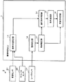
以下、図面を参照して本発明に係る衝突判定装置の実施形態について説明する。図1は、本発明に係る衝突判定装置の構成の一例を示すブロック図である。図1に示すように、本発明に係る衝突判定ECU(Electronic Control Unit)1(=衝突判定装置に相当する)は、周辺機器としての入力機器2と通信可能に接続されている。
Embodiments of a collision determination device according to the present invention will be described below with reference to the drawings. FIG. 1 is a block diagram showing an example of the configuration of a collision determination device according to the present invention. As shown in FIG. 1, a collision determination ECU (Electronic Control Unit) 1 (= corresponding to a collision determination device) according to the present invention is communicably connected to an
まず、図1を参照して、衝突判定ECU1の入力機器2について説明する。入力機器2は、車速センサ21、ヨーレートセンサ22、及び、レーダセンサ23を備えている。車速センサ21は、車速を検出するセンサであって、衝突判定ECU1(ここでは、曲率半径算出部11)に対して、車速を示す信号を出力する。
First, the
ヨーレートセンサ22は、レートジャイロ等からなり、ヨー角の変化する速さ(=車両の重心点を通る鉛直軸廻りの回転角速度)を示すヨーレートを検出するセンサであって、衝突判定ECU1(ここでは、曲率半径算出部11)に対して、ヨーレート示す信号を出力する。
The
レーダセンサ23は、例えば、ミリ波レーダ等を介して、前方車両VC2(図3参照)との相対位置及び相対速度を検出するセンサであって、衝突判定ECU1(ここでは、物体検出部12)に対して、相対位置及び相対速度を示す信号を出力する。
The
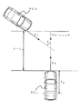
図2は、レーダセンサ23の検出範囲の一例を示す平面図である。レーダセンサ23(23R、23L)は、車両の前端部に車幅方向に2個搭載されている。各レーダセンサ23R、23Lは、それぞれ、車両の前後方向の中心線(図の一点鎖線)に対して、予め設定された所定角θ1(例えば、25°)だけ右側(又は、左側)に傾斜した方向を中心(図の二点鎖線)として、予め設定された拡がり角θ2(例えば、45°)の範囲内であって、各レーダセンサ23R、23Lからの距離が検出可能距離LR(例えば、30m)以下の領域(図の扇形の領域)を検出可能に構成されている。
FIG. 2 is a plan view showing an example of the detection range of the
本実施形態においては、車両に、レーダセンサ23が2個搭載されている場合について説明するが、レーダセンサ23が1個だけ搭載されている形態でも良いし、レーダセンサ23が3個以上搭載されている形態でも良い。また、本実施形態においては、レーダセンサ23が、前方車両VC2の相対位置及び相対速度を検出する場合について説明するが、レーダセンサ23が、後方車両を検出する形態でも良いし、側方車両を検出する形態でも良い。
In this embodiment, a case where two
次に、図1を用いて、衝突判定ECU1の機能構成について説明する。衝突判定ECU1は、機能的に、曲率半径算出部11、物体検出部12、軌道推定部13、進行方向判定部14、条件変更部15、及び、可能性判定部16を備えている。
Next, the functional configuration of the
なお、衝突判定ECU1は、衝突判定ECU1の適所に配設されたマイクロコンピュータ(コンピュータに相当する)に、衝突判定ECU1の適所に配設されたROM(Read Only Memory)等に予め格納された制御プログラムを実行させることにより、当該マイクロコンピュータを、機能的に、曲率半径算出部11、物体検出部12、軌道推定部13、進行方向判定部14、条件変更部15、可能性判定部16等の機能部として機能させる。
The
曲率半径算出部11(曲率半径算出手段に相当する)は、自車両VC1の位置する道路の曲率半径R1を求める機能部である。具体的には、曲率半径算出部11は、車速センサ21からの車速Vと、ヨーレートセンサ22からのヨーレートαとから、次の(1)式を用いて曲率半径R1を求める。
(曲率半径R1)=(車速V)/(ヨーレートα) (1)
すなわち、曲率半径算出部11は、車速Vをヨーレートαで除することによって曲率半径R1を求める。The curvature radius calculation unit 11 (corresponding to the curvature radius calculation means) is a functional unit that calculates the curvature radius R1 of the road on which the host vehicle VC1 is located. Specifically, the curvature
(Curvature radius R1) = (vehicle speed V) / (yaw rate α) (1)
That is, the curvature
このようにして、車速Vをヨーレートαで除することによって曲率半径R1が求められるため、曲率半径R1を容易に求めることができる。 In this way, the curvature radius R1 is obtained by dividing the vehicle speed V by the yaw rate α, and therefore the curvature radius R1 can be easily obtained.
本実施形態では、曲率半径算出部11が、車速V及びヨーレートαに基づいて曲率半径R1を求める場合について説明するが、曲率半径算出部11が、他の方法で、曲率半径R1を求める形態でも良い。例えば、曲率半径算出部11が、ステアリングセンサ等によって検出された操舵角に基づいて曲率半径R1を求める形態でも良い。この場合には、曲率半径R1を容易に求めることができる。また、例えば、曲率半径算出部11が、カメラ等によって検出されたセンターラインに基づいて曲率半径R1を求める形態でも良い。この場合には、曲率半径R1を正確に求めることができる。更に、例えば、曲率半径算出部11が、ナビゲーションシステム等からの地図情報に基づいて曲率半径R1を求める形態でも良い。この場合には、曲率半径R1を極めて容易に求めることができる。
In the present embodiment, the case where the curvature
物体検出部12(物体検出手段に相当する)は、レーダセンサ23を介して前方車両VC2(他の車両に相当する:図3参照)の相対位置及び相対速度を検出する機能部である。このようにして、レーダセンサ23を介して前方車両VC2の相対位置及び相対速度が検出されるため、簡素な構成で前方車両VC2の正確な相対位置及び相対速度を検出することができる。
The object detection unit 12 (corresponding to object detection means) is a functional unit that detects the relative position and relative speed of the preceding vehicle VC2 (corresponding to another vehicle: see FIG. 3) via the
本実施形態では、物体検出部12が、レーダセンサ23を介して前方車両VC2の相対位置及び相対速度を検出する場合について説明するが、物体検出部12が、その他のセンサを介して前方車両VC2の相対位置及び相対速度を検出する形態でも良い。例えば、物体検出部12が、CCD(Charge Coupled Device)センサ等の撮像センサを介して前方車両VC2の相対位置及び相対速度を検出する形態でも良い。この場合には、前方車両VC2の相対位置及び相対速度に加えて、前方車両VC2の大きさも検出することが可能である。
In the present embodiment, the case where the
軌道推定部13(軌道推定手段に相当する)は、前方車両VC2の代表点(ここでは、レーダセンサ23の捕捉点)が、今後進行する軌跡である進行軌跡を推定する機能部である。具体的には、軌道推定部13は、物体検出部12によってレーダセンサ23を介して検出された過去の前方車両VC2に関する相対位置及び相対速度に基づいて、前方車両VC2のレーダセンサ23による捕捉点が、今後進行する軌跡である進行軌跡を推定する。
The trajectory estimation unit 13 (corresponding to the trajectory estimation means) is a functional unit that estimates a travel trajectory that is a trajectory that a representative point of the forward vehicle VC2 (here, a capture point of the radar sensor 23) travels in the future. Specifically, the
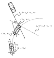
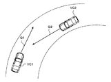
図3(a)は、軌道推定部13によって推定される進行軌跡PL2の一例を示す平面図である。この図は、自車両VC1及び前方車両VC2がカーブ路を走行中の状態を示す平面図である。図の右下の自車両VC1は、左向きに曲がるカーブ路を走行中であって、レーダセンサ23Lによって前方車両VC2が捕捉されている。図の左上の前方車両VC2は、右向きに曲がるカーブ路を走行中である。前方車両VC2の捕捉点P0は、現時点での捕捉点である。また、軌道推定部13によって、今後、前方車両VC2の捕捉点は、進行軌跡PL2に沿って移動すると推定される。すなわち、軌道推定部13によって、前方車両VC2の捕捉点は、現時点から時間ΔT、2×ΔT、3×ΔT、4×ΔT(例えば、時間ΔT=0.1秒)が経過することに対応して、捕捉点P1、P2、P3、P4の順に移動すると推定される。なお、ここでは、便宜上、自車両VC1は、前方車両VC2と比較して極めて低速で走行している(又は、停止している)場合について示している。
FIG. 3A is a plan view showing an example of the travel locus PL2 estimated by the
このようにして、前方車両VC2の代表点が、レーダセンサ23によって前方車両VC2が捕捉された捕捉点であるため、前方車両VC2の代表点を適正に設定することができる。すなわち、前方車両VC2の代表点が、レーダセンサ23によって前方車両VC2が捕捉された捕捉点であるため、前方車両VC2に関する過去の捕捉点のレーダセンサ23による検出結果(相対位置、相対速度)に基づいて、軌道推定部13が今後進行する軌跡である進行軌跡PL2を容易に推定することができるのである。
In this way, the representative point of the forward vehicle VC2 is the capture point at which the forward vehicle VC2 is captured by the
本実施形態では、前方車両VC2の代表点が、レーダセンサ23によって前方車両VC2が捕捉された捕捉点である場合について説明するが、前方車両VC2の代表点が、その他の点である形態でも良い。例えば、前方車両VC2の代表点が、前方車両VC2の車両中心点である形態でも良い。この場合には、捕捉点のように、レーダセンサ23での検出条件によって前方車両VC2における位置が変化することがないため、衝突するか否かの判定を容易に行うことができる。
In the present embodiment, the case where the representative point of the forward vehicle VC2 is a capture point where the forward vehicle VC2 is captured by the
また、ここでは、進行軌跡PL2は、軌道推定部13によって円弧として推定され、後述するように、該円弧の半径R2に基づいて、進行方向判定部14によって、前方車両VC2が進行方向を変更中であるか否かの判定がされると共に、条件変更部15によって、衝突する可能性があると判定する条件である衝突判定条件が変更される。
Further, here, the travel locus PL2 is estimated as an arc by the
再び、図1に戻って、衝突判定ECU1の機能構成について説明する。進行方向判定部14(進行方向判定手段に相当する)は、自車両VC1及び前方車両VC2の少なくとも一方が、進行方向を変更中であるか否か、を判定する機能部である。
Returning to FIG. 1 again, the functional configuration of the
具体的には、進行方向判定部14は、曲率半径算出部11によって求められた曲率半径R1に基づいて、自車両VC1が進行方向を変更中であるか否か、を判定する。更に具体的には、進行方向判定部14は、曲率半径算出部11によって求められた曲率半径R1が予め設定された閾値半径R1S(例えば、100m)以下である場合に、自車両VC1が進行方向を変更中であると判定する。
Specifically, the traveling
また、進行方向判定部14は、軌道推定部13によって求められた前方車両VC2の進行軌跡PL2の曲率半径R2に基づいて、前方車両VC2が進行方向を変更中であるか否か、を判定する。更に具体的には、進行方向判定部14は、軌道推定部13によって求められた前方車両VC2の進行軌跡PL2の曲率半径R2が、予め設定された閾値半径R2S(例えば、100m)以下である場合に、前方車両VC2が進行方向を変更中であると判定する。
Further, the traveling
このようにして、曲率半径算出部11によって求められた自車両VC1の位置する道路の曲率半径R1に基づいて、自車両VC1が進行方向を変更中であるか否かが判定されるため、自車両VC1が進行方向を変更中であるか否か、を適正に判定することができる。
In this way, it is determined whether or not the host vehicle VC1 is changing the traveling direction based on the curvature radius R1 of the road on which the host vehicle VC1 is obtained, which is obtained by the curvature
また、曲率半径算出部11によって求められた曲率半径R1が予め設定された閾値半径R1S以下である場合に、自車両VC1が進行方向を変更中であると判定されるため、自車両VC1が進行方向を変更中であるか否か、を容易に判定することができる。
In addition, when the curvature radius R1 obtained by the curvature
更に、前方車両VC2の過去における進行軌跡に基づいて求められた進行軌跡PL2の曲率半径R2に基づいて、前方車両VC2が進行方向を変更中であるか否かが判定されるため、前方車両VC2が進行方向を変更中であるか否か、を適正に判定することができる。 Further, since it is determined whether or not the forward vehicle VC2 is changing the traveling direction based on the curvature radius R2 of the traveling locus PL2 obtained based on the past traveling locus of the preceding vehicle VC2, the preceding vehicle VC2 is determined. It is possible to appropriately determine whether or not the traveling direction is being changed.
本実施形態では、進行方向判定部14が、曲率半径R1に基づいて自車両VC1が進行方向を変更中であるか否か、を判定する場合について説明するが、進行方向判定部14が、その他の方法で自車両VC1が進行方向を変更中であるか否か、を判定する形態でも良い。例えば、進行方向判定部14が、ステアリングセンサ等によって検出された操舵角に基づいて、自車両VC1が進行方向を変更中であるか否か、を判定する形態でも良い。この場合には、自車両VC1が進行方向を変更中であるか否か、を更に容易に判定することができる。
In the present embodiment, the case where the traveling
また、本実施形態では、進行方向判定部14が、曲率半径R1が予め設定された閾値半径R1S(ここでは、100m)以下である場合に、自車両VC1が進行方向を変更中であると判定する場合について説明するが、閾値半径R1Sを車速(又は、前方車両VC2との相対速度)に応じて増減する形態でも良い。例えば、車速(又は、前方車両VC2との相対速度)が大きい程、閾値半径R1Sを大きくする形態でも良い。この場合には、自車両VC1が進行方向を変更中であるか否か、を更に適正に判定することができる。
In the present embodiment, the traveling
更に、本実施形態では、進行方向判定部14が、軌道推定部13によって求められた前方車両VC2の進行軌跡PL2の曲率半径R2に基づいて、前方車両VC2が進行方向を変更中であるか否か、を判定する場合について説明するが、進行方向判定部14が、前方車両VC2の過去における進行軌跡に基づいて前方車両VC2が進行方向を変更中であるか否か、を判定する形態であれば良い。例えば、進行方向判定部14が、前方車両VC2の過去における進行軌跡の曲率半径を求め、この曲率半径に基づいて前方車両VC2が進行方向を変更中であるか否か、を判定する形態でも良い。
Further, in the present embodiment, whether or not the forward vehicle VC2 is changing the traveling direction based on the radius of curvature R2 of the traveling locus PL2 of the forward vehicle VC2 obtained by the
条件変更部15(条件変更手段に相当する)は、進行方向判定部14によって進行方向を変更中であると判定された場合に、可能性判定部16において衝突する可能性があると判定する条件である衝突判定条件を厳しくするべく変更する機能部である。
The condition changing unit 15 (corresponding to the condition changing unit) determines that there is a possibility of collision in the
具体的には、条件変更部15は、曲率半径算出部11によって求められた曲率半径R1に基づいて、可能性判定部16によって衝突の可能性の有無を判定する際に用いる前方車両VC2の仮想車長VLを変更することによって前記衝突判定条件を変更する。更に具体的には、条件変更部15は、曲率半径算出部11によって求められた曲率半径R1に比例して、次の(2)式に基づいて、前方車両VC2の仮想車長VLを変更する。
仮想車長VL=基準車長L20×R1/R1S (2)
ここで、基準車長L20は、予め設定された標準的な仮想車長(例えば、4m)である。Specifically, the
Virtual vehicle length VL = reference vehicle length L20 × R1 / R1S (2)
Here, the reference vehicle length L20 is a preset standard virtual vehicle length (for example, 4 m).
また、条件変更部15は、軌道推定部13によって求められた前方車両VC2の進行軌跡PL2の曲率半径R2に基づいて、可能性判定部16によって衝突の可能性の有無を判定する際に用いる前方車両VC2の仮想車長VLを変更することによって、衝突する可能性があると判定する条件である衝突判定条件を変更する。更に具体的には、条件変更部15は、軌道推定部13によって求められた前方車両VC2の進行軌跡PL2の曲率半径R2に比例して、次の(3)式に基づいて、前方車両VC2の仮想車長VLを変更する。
仮想車長VL=基準車長L20×R2/R2S (3)
ここで、基準車長L20は、予め設定された標準的な仮想車長(例えば、4m)である。Further, the
Virtual vehicle length VL = reference vehicle length L20 × R2 / R2S (3)
Here, the reference vehicle length L20 is a preset standard virtual vehicle length (for example, 4 m).
図5は、仮想車長VLと曲率半径R1、R2との関係の一例を示すグラフである。図5(a)は、仮想車長VLと曲率半径R1との関係の一例を示すグラフG1であり、図5(b)は、仮想車長VLと曲率半径R2との関係の一例を示すグラフG2である。図の横軸は、曲率半径R1(又は、曲率半径R2)であり、縦軸は、仮想車長VLである。 FIG. 5 is a graph showing an example of the relationship between the virtual vehicle length VL and the curvature radii R1 and R2. FIG. 5A is a graph G1 showing an example of the relationship between the virtual vehicle length VL and the curvature radius R1, and FIG. 5B is a graph showing an example of the relationship between the virtual vehicle length VL and the curvature radius R2. G2. The horizontal axis in the figure is the curvature radius R1 (or the curvature radius R2), and the vertical axis is the virtual vehicle length VL.
グラフG1(又は、グラフG2)に示すように、曲率半径R1が閾値半径R1Sより大である場合(又は、曲率半径R2が閾値半径R2Sより大である場合)には、進行方向判定部14によって自車両VC1が進行方向を変更中ではないと判定されるため、条件変更部15によって仮想車長VLが変更されることはない(=仮想車長VLは、基準車長L20に設定される)。一方、曲率半径R1が閾値半径R1S以下である場合(又は、曲率半径R2が閾値半径R2S以下である場合)には、進行方向判定部14によって自車両VC1が進行方向を変更中であると判定され、上記(2)式(又は、(3)式)に基づいて、前方車両VC2の仮想車長VLが変更される。すなわち、曲率半径R1(又は、曲率半径R2)に比例して、前方車両VC2の仮想車長VLが変更される。
As shown in the graph G1 (or graph G2), when the curvature radius R1 is larger than the threshold radius R1S (or when the curvature radius R2 is larger than the threshold radius R2S), the traveling
このようにして、曲率半径算出部11によって求められた自車両VC1の位置する道路の曲率半径R1(又は、軌道推定部13によって求められた前方車両VC2の進行軌跡PL2の曲率半径R2)に基づいて、可能性判定部16において衝突する可能性があると判定する条件である衝突判定条件が変更されるため、衝突判定条件を適正に変更することができる。
In this way, based on the curvature radius R1 of the road on which the host vehicle VC1 is obtained obtained by the curvature radius calculation unit 11 (or the curvature radius R2 of the traveling locus PL2 of the forward vehicle VC2 obtained by the trajectory estimation unit 13). Thus, since the collision determination condition, which is a condition for determining that there is a possibility of a collision in the
また、条件変更部15によって、曲率半径算出部11によって求められた自車両VC1の位置する道路の曲率半径R1(又は、軌道推定部13によって求められた前方車両VC2の進行軌跡PL2の曲率半径R2)に基づいて、前方車両VC2の仮想車長VLを変更することによって、衝突する可能性があると判定する条件である衝突判定条件が変更されため、簡素な方法で適正に衝突判定条件を厳しくするべく変更することができる。 Further, the radius of curvature R1 of the road on which the host vehicle VC1 is obtained by the condition changing unit 15 (or the radius of curvature R2 of the traveling locus PL2 of the preceding vehicle VC2 obtained by the trajectory estimating unit 13) is obtained. ) To change the virtual vehicle length VL of the preceding vehicle VC2, the collision determination condition, which is a condition for determining that there is a possibility of a collision, is changed. It can be changed as necessary.
更に、条件変更部15によって、曲率半径算出部11によって求められた自車両VC1の位置する道路の曲率半径R1(又は、軌道推定部13によって求められた前方車両VC2の進行軌跡PL2の曲率半径R2)に比例して、前方車両VC2の仮想車長VLを変更することによって、衝突する可能性があると判定する条件である衝突判定条件が変更されるため、更に簡素な方法で適正に衝突判定条件を厳しくするべく変更することができる。
Further, the curvature radius R1 of the road where the host vehicle VC1 is located, which is obtained by the curvature
本実施形態では、条件変更部15が、自車両VC1の位置する道路の曲率半径R1に基づいて、衝突判定条件を変更する場合について説明するが、条件変更部15が、曲率半径R1に換えて(又は、加えて)その他の要因に基づいて、衝突判定条件を変更する形態でも良い。例えば、条件変更部15が、ステアリングセンサ等によって検出された操舵角に基づいて、衝突判定条件を変更する形態でも良い。この場合には、処理が簡略化される。
In the present embodiment, the case where the
また、本実施形態では、条件変更部15が、前方車両VC2の仮想車長VLを変更することによって、衝突判定条件を変更する場合について説明するが、条件変更部15が、その他の方法によって、衝突判定条件を変更する形態でも良い。例えば、条件変更部15が、前方車両VC2の仮想車長VLに換えて(又は、加えて)、前方車両VC2の仮想車幅を変更する形態でも良い。なお、仮想車長VLを小さくすることによって衝突判定条件が厳しくするべく変更されることに関しては、図4を用いて後述する。
In the present embodiment, the case where the
更に、本実施形態では、条件変更部15が、曲率半径R1に比例して、前方車両VC2の仮想車長VLを変更する場合について説明するが、条件変更部15が、曲率半径R1が小さい程、前方車両VC2の仮想車長VLを小さくする形態であれば良い。例えば、条件変更部15が、曲率半径R1が小さい程、前方車両VC2の仮想車長VLを段階的に小さくする形態でも良い。また、例えば、条件変更部15が、予め設定された曲率半径R1の関数(例えば、曲率半径R1の二次式)に従って、前方車両VC2の仮想車長VLを小さくする形態でも良い。この場合には、関数を適正に設定することによって、衝突判定条件を更に適正に変更することができる。
Furthermore, although this embodiment demonstrates the case where the
再び、図1に戻って、衝突判定ECU1の機能構成について説明する。可能性判定部16(可能性判定手段に相当する)は、前方車両VC2と衝突する可能性があるか否かを判定する機能部である。具体的には、可能性判定部16は、軌跡推定部13によって推定された進行軌跡PL2上を、予め設定された車幅VB及び車長VLを有する前方車両VC2が移動する場合に、前方車両VC2が自車両VC1と交差するか否かに応じて、前方車両VC2と衝突する可能性があるか否かを判定する。
Returning to FIG. 1 again, the functional configuration of the
図3(b)は、可能性判定部16による前方車両VC2と衝突する可能性の有無を判定する処理の一例を示す平面図である。図3(a)に示すように、軌道推定部13によって、前方車両VC2の捕捉点は、現時点から時間ΔT、2×ΔT、3×ΔT、4×ΔT(例えば、時間ΔT=0.1秒)が経過することに対応して、捕捉点P1、P2、P3、P4の順に移動すると推定される。そして、図3(b)に示すように、前方車両VC2は、現時点から時間(2×ΔT)経過後には、破線で示す前方車両C22の位置に到達し、現時点から時間(4×ΔT)経過後には、破線で示す前方車両C24の位置に到達すると推定される。
FIG. 3B is a plan view illustrating an example of a process for determining whether or not there is a possibility of colliding with the preceding vehicle VC2 by the
なお、前方車両C22及び前方車両C24は、前方車両VC2と同様に、車幅VB及び車長VLを有している。また、図3(b)に示すように、前方車両C24の後部右側は、自車両VC1の前部右側と交差しているため、可能性判定部16によって前方車両VC2と衝突する可能性があると判定される。
The front vehicle C22 and the front vehicle C24 have a vehicle width VB and a vehicle length VL, similarly to the front vehicle VC2. Further, as shown in FIG. 3 (b), the rear right side of the forward vehicle C24 intersects the front right side of the host vehicle VC1, so that the
このようにして、軌跡推定部13によって推定された進行軌跡PL2上を、予め設定された車幅VB及び車長VLを有する前方車両VC2が移動する場合に、前方車両VC2が自車両VC1と交差するか否かに応じて、前方車両VC2と衝突する可能性があるか否かが判定されるため、衝突する可能性があるか否かを正確に判定することができる。
In this way, when the forward vehicle VC2 having the preset vehicle width VB and the vehicle length VL moves on the travel locus PL2 estimated by the
本実施形態では、可能性判定部16が、軌跡推定部13によって推定された進行軌跡PL2に基づいて前方車両VC2と衝突する可能性があるか否かを判定する場合について説明したが、可能性判定部16が、その他の方法で前方車両VC2と衝突する可能性があるか否かを判定する形態でも良い。例えば、可能性判定部16が、前方車両VC2の捕捉点が自車両VC1の車両中心から予め設定された所定距離(例えば、5m)以下となるタイミングにおいて、前方車両VC2が自車両VC1と交差するか否かに応じて、前方車両VC2と衝突する可能性があるか否かを判定する形態でも良い。この場合には、処理が簡略化される。
In the present embodiment, the
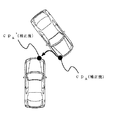
図4は、条件変更部15が前方車両VC2の仮想車長VLを小さくすることの効果の一例を示す平面図である。図4(a)は、図3(b)における自車両VC1と前方車両C24とを拡大した図である。図3(b)を用いて上述のように、前方車両C24の後部右側は、自車両VC1の前部右側と交差しているため、可能性判定部16によって前方車両VC2と衝突する可能性があると判定される。前方車両C24の仮想車長VLは、例えば、基準車長L20(ここでは、4m)である。
FIG. 4 is a plan view showing an example of the effect of the
図4(b)は、条件変更部15が前方車両VC2の仮想車長VLを小さくした場合の一例を示す平面図である。ここでは、条件変更部15によって、前方車両VC2の仮想車長VLが、基準車長L20の3/5(仮想車長L21=2.4m)に変更された場合について表記している。この場合には、図4(b)に示すように、前方車両C24’は、自車両VC1と交差していないため、可能性判定部16によって前方車両VC2と衝突する可能性はないと判定される。
FIG. 4B is a plan view showing an example when the
このようにして、仮想車長VLが、基準車長L20(ここでは、4m)から仮想車長L21(=2.4m)へ変更されることによって、可能性判定部16によって前方車両VC2と衝突する可能性があると判定されていた状況が、可能性判定部16によって前方車両VC2と衝突する可能性がないと判定される。すなわち、条件変更部15が仮想車長VLを小さくすることによって、衝突する可能性があると判定する条件である衝突判定条件を厳しくするべく変更されるのである。
In this way, the virtual vehicle length VL is changed from the reference vehicle length L20 (here, 4 m) to the virtual vehicle length L21 (= 2.4 m), so that the
図6は、図1に示す衝突判定ECU1の動作の一例を示すフローチャートである。なお、ここでは、便宜上、物体検出部12によって前方車両VC2の相対位置及び相対速度が検出されている場合について説明する。まず、曲率半径算出部11によって、車速V及びヨーレートαが取得される(S101)。そして、曲率半径算出部11によって、ステップS101において取得された車速Vを、ヨーレートαで除することによって曲率半径R1が求められる(S103)。
FIG. 6 is a flowchart showing an example of the operation of the
次に、軌道推定部13によって進行軌跡PL2が推定される(S105)。次に、進行方向判定部14によって、ステップS105において求められた進行軌跡PL2の曲率半径R2が算出される(S107)。そして、進行方向判定部14によって、ステップS103において求められた曲率半径R1が、予め設定された閾値半径R1S以下であるか否かの判定が行われる(S109)。曲率半径R1が予め設定された閾値半径R1S以下であると判定された場合(ステップS109でYES)には、進行方向判定部14によって、自車両VC1が進行方向を変更中であると判定されると共に、条件変更部15によって、次の(4)式(上述の(2)式を再掲)に基づいて、前方車両VC2の仮想車長VLが設定されて(S111)、処理がステップS119に進められる。
仮想車長VL=基準車長L20×R1/R1S (4)Next, the travel locus PL2 is estimated by the trajectory estimation unit 13 (S105). Next, the curvature direction R2 of the travel locus PL2 obtained in step S105 is calculated by the travel direction determination unit 14 (S107). Then, the traveling
Virtual vehicle length VL = reference vehicle length L20 × R1 / R1S (4)
曲率半径R1が予め設定された閾値半径R1S以下ではない(閾値半径R1Sより大である)と判定された場合(ステップS109でNO)には、進行方向判定部14によって、ステップS107において求められた曲率半径R2が、予め設定された閾値半径R2S以下であるか否かの判定が行われる(S113)。曲率半径R2が予め設定された閾値半径R2S以下であると判定された場合(ステップS113でYES)には、進行方向判定部14によって、前方車両VC2が進行方向を変更中であると判定されると共に、条件変更部15によって、次の(5)式(上述の(3)式を再掲)に基づいて、前方車両VC2の仮想車長VLが設定されて(S115)、処理がステップS119に進められる。
仮想車長VL=基準車長L20×R2/R2S (5)When it is determined that the curvature radius R1 is not less than or equal to the preset threshold radius R1S (greater than the threshold radius R1S) (NO in step S109), the traveling
Virtual vehicle length VL = reference vehicle length L20 × R2 / R2S (5)
曲率半径R2が予め設定された閾値半径R2S以下ではない(閾値半径R2Sより大である)と判定された場合(ステップS113でNO)には、進行方向判定部14によって、自車両VC1及び前方車両VC2が共に進行方向を変更中ではないと判定されて、条件変更部15によって、前方車両VC2の仮想車長VLが基準車長L20に設定される(S117)。
When it is determined that the curvature radius R2 is not less than or equal to the preset threshold radius R2S (greater than the threshold radius R2S) (NO in step S113), the traveling
ステップS111の処理が終了した場合、ステップS115の処理が終了した場合、又は、ステップS117の処理が終了した場合には、ステップS105において求められた進行軌跡PL2と、ステップS111、ステップS115、又は、ステップS117において設定された仮想車長VLと、を用いて、可能性判定部16によって、前方車両VC2と衝突する可能性があるか否かが判定され(S119)、処理が終了される。
When the process of step S111 is completed, when the process of step S115 is completed, or when the process of step S117 is completed, the travel locus PL2 obtained in step S105 and the steps S111, S115, or Using the virtual vehicle length VL set in step S117, the
このようにして、自車両VC1又は前方車両VC2が、進行方向を変更中であると判定された場合には、自車両VC1又は前方車両VC2がカーブ路を走行中であると推定される。そこで、この場合には、図13を用いて上述のように、乗員保護装置等が不要作動される虞がある。しかしながら、衝突する可能性があると判定する条件である衝突判定条件が厳しくするべく変更される(ここでは、前方車両VC2の仮想車長VLが短く設定される)ため、乗員保護装置等の不要作動を抑制することができるのである。 In this way, when it is determined that the host vehicle VC1 or the forward vehicle VC2 is changing the traveling direction, it is estimated that the host vehicle VC1 or the forward vehicle VC2 is traveling on a curved road. Therefore, in this case, as described above with reference to FIG. However, since the collision determination condition, which is a condition for determining that there is a possibility of a collision, is changed to be strict (here, the virtual vehicle length VL of the front vehicle VC2 is set short), an occupant protection device or the like is unnecessary. The operation can be suppressed.
本実施形態では、条件変更部15が、進行方向判定部14によって自車両VC1又は前方車両VC2が、進行方向を変更中であると判定されたときに、衝突判定条件を厳しくするべく変更する場合について説明したが、条件変更部15が、進行方向判定部14によって自車両VC1及び前方車両VC2の少なくとも一方が、進行方向を変更中であると判定されたときに、衝突判定条件を厳しくするべく変更する形態であれば良い。例えば、条件変更部15が、進行方向判定部14によって自車両VC1が進行方向を変更中であると判定されたときに、衝突判定条件を厳しくするべく変更する形態でも良い。また、例えば、条件変更部15が、進行方向判定部14によって自車両VC1及び前方車両VC2が進行方向を変更中であると判定されたときに、衝突判定条件を厳しくするべく変更する形態でも良い。
In the present embodiment, the
ここで、本発明に係る衝突判定装置が行う詳細な衝突判定方法の一例について述べる。以下に示す衝突判定方法は、衝突判定ECU1で実行することができる。なお、本発明における衝突判定方法は、以下の例に限定されるものではない。
Here, an example of a detailed collision determination method performed by the collision determination apparatus according to the present invention will be described. The collision determination method described below can be executed by the
まず、自車両VC1と前方車両VC2が衝突すると仮定し、衝突までの時間TTC(Time To Collision)を算出する。図7は、衝突までの時間TTCを算出する方法を示す図である。
前方車両VC2が自車両VC1に対して斜め方向から接近している場合の衝突までの時間TTCは、以下の式(6)に基づいて求めることができる。
TTC=(y−lF)/(Vn・cosδ+V0) (6)
ここで、各文字が表す意味は以下の通りである。
y:自車両VC1の後輪軸中心を原点としたときの前方車両VC2の捕捉点のY座標(自車両VC1の前後方向をY軸、自車両VC1の左右方向をX軸とする)、lF:自車両VC1の後輪軸中心から先端部中心までの長さ、Vn:前方車両VC2の速度、δ:前方車両VC2の進行方向と自車両VC1の進行方向がなす角度、V0:自車両VC1の速度First, assuming that the host vehicle VC1 and the preceding vehicle VC2 collide, a time TTC (Time To Collision) until the collision is calculated. FIG. 7 is a diagram illustrating a method for calculating the time TTC until the collision.
The time TTC until the collision when the preceding vehicle VC2 approaches the host vehicle VC1 from an oblique direction can be obtained based on the following equation (6).
TTC = (y−1 F ) / (V n · cos δ + V 0 ) (6)
Here, the meaning of each character is as follows.
y: Y coordinate of the capture point of the forward vehicle VC2 when the center of the rear wheel axis of the host vehicle VC1 is the origin (the front and rear direction of the host vehicle VC1 is the Y axis, and the left and right direction of the host vehicle VC1 is the X axis), l F : from wheel axis center after the vehicle VC1 to the tip center length, V n: the speed of the forward vehicle VC2, [delta]: traveling direction traveling direction angle between the own vehicle VC1 of the forward vehicle VC2, V 0: vehicle VC1 speed
なお、レーダセンサ23は、周期的に前方車両VC2の相対位置(捕捉点の位置)及び相対速度(捕捉点の速度)を算出し、過去複数周期分(例えば過去10周期分)の相対位置及び相対速度に基づいて進行方向ベクトルを算出する。進行方向ベクトルの算出には、例えば、最小二乗法を用いることができる。Vnは、算出した進行方向ベクトルの大きさである。The
次いで、自車両VC1が旋回中であるものとして、時間TTC後の予想自車位置を算出する。図8は、時間TTC後の予想自車位置を算出する方法を説明する図である。
自車両VC1の予想偏向角θFおよび予想自車位置(XF,YF)は、以下の式(7)、(8)、(9)から求めることができる。
θF=θ0+V0・TTC/(−R) (7)
XF=X0+V0・TTC・sin(−θF) (8)
YF=Y0+V0・TTC・cos(−θF) (9)
ここで、各文字が表す意味は以下の通りである。
θ0:自車両VC1の現在位置における偏向角、V0:自車両VC1の速度、R:自車両VC1の進行軌跡の旋回半径、X0:自車両VC1の現在位置のX座標、Y0:自車両VC1の現在位置のY座標Next, assuming that the host vehicle VC1 is turning, the predicted host vehicle position after time TTC is calculated. FIG. 8 is a diagram for explaining a method of calculating the predicted vehicle position after time TTC.
The predicted deflection angle θ F and the predicted host vehicle position (X F , Y F ) of the host vehicle VC1 can be obtained from the following equations (7), (8), (9).
θ F = θ 0 + V 0 · TTC / (− R) (7)
X F = X 0 + V 0 · TTC · sin (−θ F ) (8)
Y F = Y 0 + V 0 · TTC · cos (−θ F ) (9)
Here, the meaning of each character is as follows.
θ 0 : deflection angle at the current position of the
次いで、算出された予想自車位置の情報に基づき、自車両VC1が予想自車位置に到達したときにおける自車両VC1の前面延長線の式を求める。自車両VC1の後輪軸中心を原点とする座標系(図8(A)参照)における前面延長線y=lFを、地上に原点を固定した座標系(図8(B)参照)の式(10)に変換する。
pFX+qFY+rF=0 (10)Next, based on the calculated information on the predicted host vehicle position, an expression of the front extension line of the host vehicle VC1 when the host vehicle VC1 reaches the predicted host vehicle position is obtained. Formula of a coordinate system (see FIG. 8 (B)) in which the front extension line y = l F in the coordinate system (see FIG. 8 (A)) having the origin at the center of the rear wheel axis of the host vehicle VC1 is fixed to the ground. 10).
p F X + q F Y + r F = 0 (10)
その際、桁溢れを防ぐために、式(11)〜(13)、式(14)〜(16)に示されるように、θFの範囲で場合分けを行う。At that time, in order to prevent the overflow, formula (11) to (13), as shown in equation (14) to (16), performs the classification if the range of theta F.
(π/4<|θF|≦3π/4の場合)
pF=1 (11)
qF=cos(−θF)/sin(−θF) (12)
rF=(−lF−XFsin(−θF)−YFcos(−θF))
/sin(−θF) (13)(If π / 4 <| θ F | ≦ 3π / 4)
p F = 1 (11)
q F = cos (-θ F) / sin (-θ F) (12)
r F = (- l F -X F sin (-θ F) -Y F cos (-θ F))
/ Sin (−θ F ) (13)
(3π/4<|θF|≦πの場合)
pF=sin(−θF)/cos(−θF) (14)
qF=1 (15)
rF=(−lF−XFsin(−θF)−YFcos(−θF))
/cos(−θF) (16)(When 3π / 4 <| θ F | ≦ π)
p F = sin (-θ F) / cos (-θ F) (14)
q F = 1 (15)
r F = (- l F -X F sin (-θ F) -Y F cos (-θ F))
/ Cos (−θ F ) (16)
次いで、前方車両VC2の軌道予測線pnX+qnY+rn=0を求める。
pnX+qnY+rn=0の各係数は、前方車両VC2の過去の捕捉点履歴に基づいて求めることができる。例えば、過去の複数の捕捉点に最小二乗法を適用することで進行方向ベクトルを求め、そのベクトルを延ばした直線を軌道予測線とすることができる。Then, determine the trajectory prediction line p n X + q n Y + r n = 0 of the forward vehicle VC2.
Each coefficient of p n X + q n Y + r n = 0 can be determined based on the past capture point history of the forward vehicle VC2. For example, a traveling direction vector can be obtained by applying the least square method to a plurality of past acquisition points, and a straight line obtained by extending the vector can be used as a trajectory prediction line.
次いで、式(10)の直線pFX+qFY+rF=0と前方車両VC2の軌道予測線pnX+qnY+rn=0の交点を求める。この交点は、自車両VC1と前方車両VC2の予想衝突点である。予想衝突点の座標(XC,YC)は以下の式(17)〜(20)で表される。図9は、予想衝突点を示す図である。なお、座標(XC,YC)は、地上に原点を固定した座標系(地上座標系)における座標である。
Then, determine the intersection of the straight line p F X + q F Y + r F = 0 trajectory prediction line and the preceding vehicle VC2 p n X + q n Y + r n = 0 in formula (10). This intersection is an expected collision point between the host vehicle VC1 and the preceding vehicle VC2. The coordinates (X C , Y C ) of the predicted collision point are expressed by the following equations (17) to (20). FIG. 9 is a diagram illustrating an expected collision point. The coordinates (X C , Y C ) are coordinates in a coordinate system (ground coordinate system) in which the origin is fixed on the ground.
(π/4<|θF|≦3π/4の場合)
XC=−qFYC/pF−rF/pF (17)
YC=(pnrF−pFrn)/(pFqn−pnqF) (18)(If π / 4 <| θ F | ≦ 3π / 4)
X C = -q F Y C / p F -r F / p F (17)
Y C = (p n r F -p F r n) / (p F q n -p n q F) (18)
(0≦|θF|≦π/4または3π/4<|θF|≦πの場合)
XC=(qFrn−qnrF)/(pFqn−pnqF) (19)
YC=−pFXC/qF−rF/pF (20)
pFqn−pnqF=0のとき、これらの直線は互いに平行となり、交点が存在しないので、衝突可能性無しと判定される。(When 0 ≦ | θ F | ≦ π / 4 or 3π / 4 <| θ F | ≦ π)
X C = (q F r n -q n r F) / (p F q n -p n q F) (19)
Y C = -p F X C / q F -r F / p F (20)
When p F q n -p n q F = 0, these lines are mutually parallel, since the intersection does not exist, it is determined that no collision possibility.
自車両VC1の前端部中央を原点とし、自車両VC1の前後方向をY軸方向、自車両VC1の幅方向をX軸方向とする座標系(cp座標系、図10参照)では、予想衝突点(cpx,cpy)は以下の式(21)(22)で表される。
cpx=cos(−θF)(XC−XF)
−sin(−θF)(YC−YF) (21)
cpy=0 (22)
式(21)に式(7)(8)(9)(17)(18)(19)(20)で算出した値を代入することで、予想衝突点(cpx,cpy)を算出することができる。In a coordinate system (cp coordinate system, see FIG. 10) where the center of the front end of the host vehicle VC1 is the origin, the longitudinal direction of the host vehicle VC1 is the Y-axis direction, and the width direction of the host vehicle VC1 is the X-axis direction. (Cp x , cp y ) is expressed by the following equations (21) and (22).
cp x = cos (−θ F ) (X C −X F )
-Sin (-θ F) (Y C -Y F) (21)
cp y = 0 (22)
The predicted collision point (cp x , cp y ) is calculated by substituting the values calculated in equations (7), (8), (9), (17), (18), (19), and (20) into equation (21). be able to.
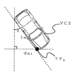
ここで、cpxは前方車両VC2の大きさを考慮していないので、当該大きさを考慮した式に補正する。
補正後のcpx’は以下の式(23)(24)で表される。
(前方車両VC2が「左斜め前」から接近する場合、図11参照)
cpx’=cpx−dmε・σ・σR (23)
(前方車両VC2が「右斜め前」から接近する場合)
cpx’=cpx+dmε・σ・σR (24)Here, since cp x does not consider the size of the preceding vehicle VC2, it is corrected to an equation that takes the size into consideration.
The corrected cp x ′ is expressed by the following equations (23) and (24).
(When the front vehicle VC2 approaches from “left diagonally forward”, see FIG. 11)
cp x '= cp x -d mε · σ · σ R (23)
(When forward vehicle VC2 approaches from “right diagonally forward”)
cp x '= cp x + d mε · σ · σ R (24)
ここで、各文字が表す意味は以下の通りである。
dmε=lm・sinε (25)
ε:自車両VC1の前後方向に対して前方車両VC2の接近方向がなす角度(図12参照)
lm:前方車両VC2の長さ(上述した基準車長に相当する)
(前方車両VC2が「左斜め前」から接近する場合)
σ=cpx/(dR+dmε・σR) (26)
(前方車両VC2が「右斜め前」から接近する場合)
σ=−cpx/(dR+dmε・σR) (27)Here, the meaning of each character is as follows.
d mε = l m · sinε (25)
ε: angle formed by the approach direction of the front vehicle VC2 with respect to the front-rear direction of the host vehicle VC1 (see FIG. 12)
l m : length of the forward vehicle VC2 (corresponding to the above-mentioned reference vehicle length)
(When forward vehicle VC2 approaches from “left diagonally forward”)
σ = cp x / (d R + d mε · σ R ) (26)
(When forward vehicle VC2 approaches from “right diagonally forward”)
σ = −cp x / (d R + d mε · σ R ) (27)
σR=|R|/|RTH| (0≦σR≦1) (28)
ここで、|R|:道路の曲率半径の絶対値(Rは右カーブでは正、左カーブでは負の値で表されるため)、|RTH|:σの補正を行う|R|の上限値(例えば100m)σ R = | R | / | R TH | (0 ≦ σ R ≦ 1) (28)
Where | R |: absolute value of the curvature radius of the road (since R is represented by a positive value on the right curve and a negative value on the left curve), | R TH |: an upper limit of | R | Value (eg 100m)
式(28)によれば、道路の曲率半径の絶対値|R|が小さい程、σRが小さくなる。そうすると、道路の曲率半径の絶対値|R|が小さい程、式(25)で示される前方車両VC2の長さlmにより小さい補正係数σRが掛けられることを意味する。lm・σRは、上述した仮想車長に相当する。これは、前方車両VC2の長さがカーブの曲率半径に応じて小さい値に補正されることであり、本願発明の特徴を表している。According to Expression (28), σ R decreases as the absolute value | R | of the curvature radius of the road decreases. Then, the absolute value of the curvature radius of the road | R | the smaller, means a smaller correction coefficient σ that R is applied to the length l m of the forward vehicle VC2 of the formula (25). l m · σ R corresponds to the above-described virtual vehicle length. This is that the length of the front vehicle VC2 is corrected to a small value in accordance with the curvature radius of the curve, and represents the feature of the present invention.
式(23)(24)で算出されたcpx’が自車両VC1の幅の半分dR未満である場合は、自車両VC1と前方車両VC2が衝突すると判定される。
一方、cpx’が自車両VC1の幅の半分dR以上である場合は、自車両VC1と前方車両VC2は衝突しないと判定される。When cp x ′ calculated by Expressions (23) and (24) is less than half d R of the width of the host vehicle VC1, it is determined that the host vehicle VC1 and the preceding vehicle VC2 collide.
On the other hand, if cp x 'is equal to or greater than half d R of the width of the vehicle VC1 is the vehicle VC1 and the forward vehicle VC2 is determined not to collide.
上記した衝突判定は、レーダセンサ23の捕捉点算出周期毎に行われる。衝突すると判定した周期が所定回数連続した場合、或いは、衝突すると判定した周期の割合が所定の割合以上となった場合に、警報音を鳴らしたり、ブレーキアシスト等の安全措置が実行される。
The above-described collision determination is performed at every capture point calculation period of the
なお、本発明に係る衝突判定装置は、上記実施形態に係る衝突判定ECU1に限定されず、下記の形態でも良い。
(A)本実施形態においては、衝突判定ECU1が、機能的に、曲率半径算出部11、物体検出部12、軌道推定部13、進行方向判定部14、条件変更部15、可能性判定部16等を備える場合について説明したが、曲率半径算出部11、物体検出部12、軌道推定部13、進行方向判定部14、条件変更部15、及び、可能性判定部16の内、少なくとも1つの機能部が、電気回路等のハードウェアによって構成されている形態でも良い。The collision determination device according to the present invention is not limited to the
(A) In the present embodiment, the
(B)本実施形態においては、衝突判定装置が、衝突判定ECU1からなる場合について説明したが、衝突判定装置が、センサ等の一部と一体に構成されている形態でも良い。例えば、衝突判定装置が、レーダセンサ23と一体に構成されている形態(例えば、レーダセンサ23の信号処理を行う制御装置と一体に構成されている形態)でも良い。
(B) In the present embodiment, the case where the collision determination device includes the
(C)本実施形態においては、条件変更部15が、曲率半径R1に比例して、前方車両VC2の仮想車長VLを変更する場合について説明したが、条件変更部15が、前方車両VC2の大きさに基づいて前方車両VC2の仮想車長VLを変更する形態でも良い。例えば、条件変更部15が、次の(6)式に基づいて仮想車長VLを変更する形態でも良い。
仮想車長VL=γ×検出車長L200×R1/R1S (6)
ここで、係数γは、前方車両VC2の大きさに基づいて設定される係数であり、検出車長L200は、レーダセンサ23による捕捉点の個数、位置等から推定される前方車両VC2の車長である。(C) Although the case where the
Virtual vehicle length VL = γ × detected vehicle length L200 × R1 / R1S (6)
Here, the coefficient γ is a coefficient set based on the size of the forward vehicle VC2, and the detected vehicle length L200 is the vehicle length of the forward vehicle VC2 estimated from the number, position, etc. of the capture points by the
また、検出車長L200が大きい場合(=前方車両VC2が大型車である場合)には、係数γを「1」より小さな値(例えば、0.8)に設定し、検出車長L200が小さい場合(=前方車両VC2が小型車である場合)には、係数γを「1」より大きな値(例えば、1.2)に設定することが好ましい。このようにすると、前方車両VC2が大型車である場合には、曲率半径R1による仮想車長VLの変化量が大きくなるため、乗員保護装置等の不要作動を更に効果的に抑制することができるのである。 When the detected vehicle length L200 is large (= when the forward vehicle VC2 is a large vehicle), the coefficient γ is set to a value smaller than “1” (for example, 0.8), and the detected vehicle length L200 is small. In the case (= when the front vehicle VC2 is a small vehicle), it is preferable to set the coefficient γ to a value larger than “1” (for example, 1.2). In this way, when the front vehicle VC2 is a large vehicle, the amount of change in the virtual vehicle length VL due to the radius of curvature R1 increases, so that unnecessary operations of the passenger protection device and the like can be more effectively suppressed. It is.
(D)本実施形態においては、条件変更部15が、前方車両VC2の仮想車長VLを変更する場合について説明したが、条件変更部15が、その他の方法で、衝突判定条件を厳しくするべく変更する形態でも良い。すなわち、可能性判定部16が、衝突する可能性があるか否かを判定する方法に応じて、適宜、条件変更部15が衝突判定条件を厳しくするべく変更する方法を設定すれば良い。
(D) In the present embodiment, the case where the
例えば、可能性判定部16が、所定時間経過後の前方車両VC2の進行方向ベクトルに対応する向きが予め設定された範囲(=以下、「方向判定範囲」という)にあるか否かに基づいて、衝突する可能性があるか否かを判定する場合について説明する。この場合には、条件変更部15は、上記「方向判定範囲」を狭くすることによって、衝突判定条件を厳しくすれば良い。
For example, the
本発明は、例えば、車両に搭載され、他の車両と衝突する可能性の有無を判定する衝突判定装置に適用することができる。 The present invention can be applied to, for example, a collision determination device that is mounted on a vehicle and determines whether or not there is a possibility of collision with another vehicle.
Claims (12)
前記他の車両と衝突する可能性があるか否かを判定する可能性判定手段と、
自車両及び前記他の車両の少なくとも一方が、カーブ路を走行中であるか否か、を判定する進行方向判定手段と、
前記進行方向判定手段によってカーブ路を走行中であると判定された場合に、前記可能性推定手段において衝突する可能性があると判定する条件である衝突判定条件を厳しくするべく変更する条件変更手段と、を備える衝突判定装置。A collision determination device that is mounted on a vehicle and determines whether or not there is a possibility of collision with another vehicle,
Possibility determination means for determining whether or not there is a possibility of collision with the other vehicle;
Traveling direction determination means for determining whether at least one of the host vehicle and the other vehicle is traveling on a curved road;
Condition change means for changing the collision determination condition, which is a condition for determining that there is a possibility of collision in the possibility estimation means, when the traveling direction determination means determines that the vehicle is traveling on a curved road. A collision determination device comprising:
前記可能性推定手段は、前記軌跡推定手段によって推定された進行軌跡上を、予め設定された車幅及び車長を有する前記他の車両が移動する場合に、前記他の車両が自車両と交差するか否かに応じて、前記他の車両と衝突する可能性があるか否かを判定する、請求項1に記載の衝突判定装置。The representative point of the other vehicle is provided with a trajectory estimating means for estimating a travel trajectory that is a trajectory that will proceed in the future,
When the other vehicle having a preset vehicle width and vehicle length moves on the traveling locus estimated by the locus estimating means, the possibility estimating means intersects with the own vehicle. The collision determination apparatus according to claim 1, wherein it is determined whether or not there is a possibility of a collision with the other vehicle depending on whether or not to do so.
前記他の車両の代表点は、前記レーダによって前記他の車両が捕捉された捕捉点である、請求項2に記載の衝突判定装置。Object detection means for detecting the position of the other vehicle via a radar,
The collision determination apparatus according to claim 2, wherein the representative point of the other vehicle is a capture point where the other vehicle is captured by the radar.
前記進行方向判定手段は、前記曲率半径算出手段によって求められた曲率半径に基づいて、自車両がカーブ路を走行中であるか否か、を判定する、請求項1に記載の衝突判定装置。A radius-of-curvature calculation means for obtaining a radius of curvature of the road where the host vehicle is located,
The collision determination device according to claim 1, wherein the traveling direction determination unit determines whether the host vehicle is traveling on a curved road based on the curvature radius obtained by the curvature radius calculation unit.
前記条件変更手段は、前記曲率半径算出手段によって求められた曲率半径に基づいて、前記衝突判定条件を変更する、請求項1に記載の衝突判定装置。A radius-of-curvature calculation means for obtaining a radius of curvature of the road where the host vehicle is located,
The collision determination device according to claim 1, wherein the condition changing unit changes the collision determination condition based on the curvature radius obtained by the curvature radius calculation unit.
前記条件変更手段は、前記曲率半径算出手段によって求められた曲率半径に基づいて、前記他の車両の車幅及び車長の少なくとも一方を変更することによって前記衝突判定条件を変更する、請求項2に記載の衝突判定装置。A radius-of-curvature calculation means for obtaining a radius of curvature of the road where the host vehicle is located,
The condition change means changes the collision determination condition by changing at least one of a vehicle width and a vehicle length of the other vehicle based on the curvature radius obtained by the curvature radius calculation means. The collision determination apparatus described in 1.
Applications Claiming Priority (1)
| Application Number | Priority Date | Filing Date | Title |
|---|---|---|---|
| PCT/JP2008/003927 WO2010073297A1 (en) | 2008-12-24 | 2008-12-24 | Collision determination device |
Publications (2)
| Publication Number | Publication Date |
|---|---|
| JP4831442B2 true JP4831442B2 (en) | 2011-12-07 |
| JPWO2010073297A1 JPWO2010073297A1 (en) | 2012-05-31 |
Family
ID=42286969
Family Applications (1)
| Application Number | Title | Priority Date | Filing Date |
|---|---|---|---|
| JP2010543643A Active JP4831442B2 (en) | 2008-12-24 | 2008-12-24 | Collision determination device |
Country Status (4)
| Country | Link |
|---|---|
| US (1) | US8483944B2 (en) |
| JP (1) | JP4831442B2 (en) |
| DE (1) | DE112008004238B4 (en) |
| WO (1) | WO2010073297A1 (en) |
Families Citing this family (18)
| Publication number | Priority date | Publication date | Assignee | Title |
|---|---|---|---|---|
| JP5146542B2 (en) * | 2008-12-26 | 2013-02-20 | トヨタ自動車株式会社 | Traveling route estimation device and traveling route estimation method used in the device |
| EP2347940A1 (en) * | 2010-01-25 | 2011-07-27 | Autoliv Development AB | An object collision warning system and method for a motor vehicle |
| US8466807B2 (en) * | 2011-06-01 | 2013-06-18 | GM Global Technology Operations LLC | Fast collision detection technique for connected autonomous and manual vehicles |
| WO2013101055A1 (en) * | 2011-12-29 | 2013-07-04 | Intel Corporation | Navigation systems that enhance driver awareness |
| US9200904B2 (en) * | 2013-03-15 | 2015-12-01 | Caterpillar | Traffic analysis system utilizing position based awareness |
| JP5979259B2 (en) * | 2015-01-20 | 2016-08-24 | トヨタ自動車株式会社 | Collision avoidance control device |
| JP6361698B2 (en) * | 2016-06-24 | 2018-07-25 | トヨタ自動車株式会社 | Collision avoidance device |
| US10025319B2 (en) * | 2016-08-31 | 2018-07-17 | Ford Global Technologies, Llc | Collision-warning system |
| JP6609237B2 (en) * | 2016-11-17 | 2019-11-20 | 株式会社デンソー | Collision determination device and collision determination method |
| JP7298744B2 (en) * | 2016-12-07 | 2023-06-27 | スズキ株式会社 | Driving support device |
| JP6515912B2 (en) | 2016-12-22 | 2019-05-22 | トヨタ自動車株式会社 | Vehicle driving support device |
| JP6544348B2 (en) * | 2016-12-22 | 2019-07-17 | トヨタ自動車株式会社 | Vehicle driving support device |
| US11158193B2 (en) * | 2017-05-22 | 2021-10-26 | Mitsubishi Electric Corporation | Position estimation apparatus, position estimation method, and computer readable medium |
| JP7135808B2 (en) * | 2018-12-07 | 2022-09-13 | トヨタ自動車株式会社 | Collision avoidance support device |
| CN109693669B (en) * | 2018-12-29 | 2021-02-19 | 北京经纬恒润科技股份有限公司 | Method and system for determining nearest on-path front vehicle |
| KR102589935B1 (en) * | 2019-04-18 | 2023-10-18 | 현대모비스 주식회사 | Apparatus and method for monitoring camera signals |
| CN114643983B (en) * | 2020-12-17 | 2025-08-15 | 深圳引望智能技术有限公司 | Control method and device |
| JP2024109318A (en) * | 2023-02-01 | 2024-08-14 | トヨタ自動車株式会社 | Driving Support Devices |
Citations (8)
| Publication number | Priority date | Publication date | Assignee | Title |
|---|---|---|---|---|
| JPH07262499A (en) * | 1994-03-25 | 1995-10-13 | Nippondenso Co Ltd | Obstacle alarm device for vehicle |
| JPH0991598A (en) * | 1995-09-25 | 1997-04-04 | Mazda Motor Corp | Obstacle detecting device for vehicle |
| JPH10172098A (en) * | 1996-12-13 | 1998-06-26 | Denso Corp | Vehicle velocity control method, its device and storage medium |
| JP2000326757A (en) * | 1999-05-18 | 2000-11-28 | Mitsubishi Electric Corp | Danger approach prevention device |
| JP2004078333A (en) * | 2002-08-12 | 2004-03-11 | Nissan Motor Co Ltd | Travel route generator |
| JP2007091102A (en) * | 2005-09-29 | 2007-04-12 | Toyota Motor Corp | Obstacle detection device |
| JP2007153203A (en) * | 2005-12-07 | 2007-06-21 | Nissan Motor Co Ltd | Rear side warning device and method for vehicle |
| JP2007279892A (en) * | 2006-04-04 | 2007-10-25 | Honda Motor Co Ltd | Collision prediction system control apparatus, collision prediction method, and occupant protection system |
Family Cites Families (19)
| Publication number | Priority date | Publication date | Assignee | Title |
|---|---|---|---|---|
| US5388048A (en) * | 1993-02-16 | 1995-02-07 | Silicon Heights Limited | Vehicle anti-collison device |
| US5754099A (en) | 1994-03-25 | 1998-05-19 | Nippondenso Co., Ltd. | Obstacle warning system for a vehicle |
| US5964822A (en) * | 1997-08-27 | 1999-10-12 | Delco Electronics Corp. | Automatic sensor azimuth alignment |
| DE19750338A1 (en) * | 1997-11-13 | 1999-05-20 | Siemens Ag | Motor vehicle cruise control system |
| JP2000357299A (en) * | 1999-06-16 | 2000-12-26 | Honda Motor Co Ltd | Vehicle safety devices |
| JP3896852B2 (en) * | 2002-01-16 | 2007-03-22 | 株式会社デンソー | Vehicle collision damage reduction device |
| US7009500B2 (en) * | 2002-02-13 | 2006-03-07 | Ford Global Technologies, Llc | Method for operating a pre-crash sensing system in a vehicle having a countermeasure system using stereo cameras |
| US6950014B2 (en) * | 2002-02-13 | 2005-09-27 | Ford Global Technologies Llc | Method for operating a pre-crash sensing system in a vehicle having external airbags |
| US6794987B2 (en) * | 2002-07-01 | 2004-09-21 | Delphi Technologies, Inc. | Object detection system and method of estimating object size |
| US7522091B2 (en) * | 2002-07-15 | 2009-04-21 | Automotive Systems Laboratory, Inc. | Road curvature estimation system |
| JP2004136785A (en) | 2002-10-17 | 2004-05-13 | Toyota Motor Corp | Vehicle control device |
| DE602004016520D1 (en) * | 2003-07-11 | 2008-10-23 | Toyota Motor Co Ltd | IMPACT SAFETY VEHICLE CONTROL SYSTEM |
| JP2005254835A (en) * | 2004-03-09 | 2005-09-22 | Hitachi Ltd | Vehicle travel control device and vehicle control unit |
| DE102004048530A1 (en) * | 2004-10-06 | 2006-04-13 | Daimlerchrysler Ag | Collision avoidance system for long vehicles that determines available space, required space and calculates a trajectory dependent on driver strategy and driving situation |
| US7864032B2 (en) * | 2005-10-06 | 2011-01-04 | Fuji Jukogyo Kabushiki Kaisha | Collision determination device and vehicle behavior control device |
| JP2007137126A (en) | 2005-11-15 | 2007-06-07 | Mazda Motor Corp | Obstacle detecting device for vehicle |
| US8583301B2 (en) * | 2008-02-15 | 2013-11-12 | Ford Global Technologies, Llc | Engine speed control for an engine in a hybrid electric vehicle powertrain for improved noise, vibration and harshness |
| JP5210233B2 (en) * | 2009-04-14 | 2013-06-12 | 日立オートモティブシステムズ株式会社 | Vehicle external recognition device and vehicle system using the same |
| EP2302412B1 (en) * | 2009-09-29 | 2012-08-15 | Volvo Car Corporation | System and method for evaluation of an automotive vehicle forward collision threat |
-
2008
- 2008-12-24 JP JP2010543643A patent/JP4831442B2/en active Active
- 2008-12-24 WO PCT/JP2008/003927 patent/WO2010073297A1/en not_active Ceased
- 2008-12-24 US US13/139,595 patent/US8483944B2/en active Active
- 2008-12-24 DE DE112008004238.1T patent/DE112008004238B4/en active Active
Patent Citations (8)
| Publication number | Priority date | Publication date | Assignee | Title |
|---|---|---|---|---|
| JPH07262499A (en) * | 1994-03-25 | 1995-10-13 | Nippondenso Co Ltd | Obstacle alarm device for vehicle |
| JPH0991598A (en) * | 1995-09-25 | 1997-04-04 | Mazda Motor Corp | Obstacle detecting device for vehicle |
| JPH10172098A (en) * | 1996-12-13 | 1998-06-26 | Denso Corp | Vehicle velocity control method, its device and storage medium |
| JP2000326757A (en) * | 1999-05-18 | 2000-11-28 | Mitsubishi Electric Corp | Danger approach prevention device |
| JP2004078333A (en) * | 2002-08-12 | 2004-03-11 | Nissan Motor Co Ltd | Travel route generator |
| JP2007091102A (en) * | 2005-09-29 | 2007-04-12 | Toyota Motor Corp | Obstacle detection device |
| JP2007153203A (en) * | 2005-12-07 | 2007-06-21 | Nissan Motor Co Ltd | Rear side warning device and method for vehicle |
| JP2007279892A (en) * | 2006-04-04 | 2007-10-25 | Honda Motor Co Ltd | Collision prediction system control apparatus, collision prediction method, and occupant protection system |
Also Published As
| Publication number | Publication date |
|---|---|
| US8483944B2 (en) | 2013-07-09 |
| WO2010073297A1 (en) | 2010-07-01 |
| US20110246071A1 (en) | 2011-10-06 |
| JPWO2010073297A1 (en) | 2012-05-31 |
| DE112008004238T5 (en) | 2012-07-12 |
| DE112008004238B4 (en) | 2016-10-13 |
Similar Documents
| Publication | Publication Date | Title |
|---|---|---|
| JP4831442B2 (en) | Collision determination device | |
| JP4706984B2 (en) | Collision estimation apparatus and collision estimation method | |
| JP4869858B2 (en) | Vehicle travel control system | |
| US9352778B2 (en) | Lane keeping assist system and method | |
| CN102077259B (en) | Vehicle relative position estimation apparatus and vehicle relative position estimation method | |
| US8847792B2 (en) | Object detection apparatus and object detection program | |
| US11338801B2 (en) | Collision avoidance device | |
| JP5120140B2 (en) | Collision estimation device and collision estimation program | |
| JP4832489B2 (en) | Lane judgment device | |
| JP6451857B2 (en) | Method for controlling travel control device and travel control device | |
| CN106053879A (en) | Fail operational vehicle speed estimation through data fusion | |
| JP6020729B2 (en) | Vehicle position / posture angle estimation apparatus and vehicle position / posture angle estimation method | |
| KR20190056977A (en) | Vehicle control device | |
| US20080278349A1 (en) | Vehicle Deviation Preventing Control Device | |
| JP6011625B2 (en) | Speed calculation device, speed calculation method, and collision determination device | |
| JP6207952B2 (en) | Leading vehicle recognition device | |
| JP2018045426A (en) | Collision probability estimation device | |
| JP5561469B2 (en) | Yaw rate correction apparatus and method | |
| JP2008302850A (en) | Collision determination device | |
| KR20180006635A (en) | System for avoiding collision in crossroad and method for control thereof | |
| JP4876847B2 (en) | Vehicle traveling direction estimation device and driving support system | |
| JP7056379B2 (en) | Vehicle driving control device | |
| TWI719663B (en) | Lateral trajectory tracking method and system for lane change control | |
| KR102277479B1 (en) | Apparatus and method for estimating radius of curvature in vehicle | |
| WO2021015065A1 (en) | Collision damage reduction device |
Legal Events
| Date | Code | Title | Description |
|---|---|---|---|
| TRDD | Decision of grant or rejection written | ||
| A975 | Report on accelerated examination |
Free format text: JAPANESE INTERMEDIATE CODE: A971005 Effective date: 20110823 |
|
| A01 | Written decision to grant a patent or to grant a registration (utility model) |
Free format text: JAPANESE INTERMEDIATE CODE: A01 Effective date: 20110825 |
|
| A01 | Written decision to grant a patent or to grant a registration (utility model) |
Free format text: JAPANESE INTERMEDIATE CODE: A01 |
|
| A61 | First payment of annual fees (during grant procedure) |
Free format text: JAPANESE INTERMEDIATE CODE: A61 Effective date: 20110907 |
|
| R151 | Written notification of patent or utility model registration |
Ref document number: 4831442 Country of ref document: JP Free format text: JAPANESE INTERMEDIATE CODE: R151 |
|
| FPAY | Renewal fee payment (event date is renewal date of database) |
Free format text: PAYMENT UNTIL: 20140930 Year of fee payment: 3 |