JP4830833B2 - Sphygmomanometer - Google Patents
Sphygmomanometer Download PDFInfo
- Publication number
- JP4830833B2 JP4830833B2 JP2006337375A JP2006337375A JP4830833B2 JP 4830833 B2 JP4830833 B2 JP 4830833B2 JP 2006337375 A JP2006337375 A JP 2006337375A JP 2006337375 A JP2006337375 A JP 2006337375A JP 4830833 B2 JP4830833 B2 JP 4830833B2
- Authority
- JP
- Japan
- Prior art keywords
- block
- cuff
- angle
- pedestal
- respect
- Prior art date
- Legal status (The legal status is an assumption and is not a legal conclusion. Google has not performed a legal analysis and makes no representation as to the accuracy of the status listed.)
- Expired - Fee Related
Links
- NJPPVKZQTLUDBO-UHFFFAOYSA-N novaluron Chemical compound C1=C(Cl)C(OC(F)(F)C(OC(F)(F)F)F)=CC=C1NC(=O)NC(=O)C1=C(F)C=CC=C1F NJPPVKZQTLUDBO-UHFFFAOYSA-N 0.000 claims description 39
- 238000009530 blood pressure measurement Methods 0.000 claims description 13
- 230000036772 blood pressure Effects 0.000 claims description 10
- 208000028867 ischemia Diseases 0.000 claims description 4
- 210000001364 upper extremity Anatomy 0.000 claims description 2
- 238000001514 detection method Methods 0.000 claims 1
- 239000008280 blood Substances 0.000 abstract 1
- 210000004369 blood Anatomy 0.000 abstract 1
- 238000003780 insertion Methods 0.000 description 7
- 230000037431 insertion Effects 0.000 description 7
- 238000004804 winding Methods 0.000 description 7
- 210000000245 forearm Anatomy 0.000 description 3
- 238000005259 measurement Methods 0.000 description 2
- 238000000034 method Methods 0.000 description 1
Images
Classifications
-
- A—HUMAN NECESSITIES
- A61—MEDICAL OR VETERINARY SCIENCE; HYGIENE
- A61B—DIAGNOSIS; SURGERY; IDENTIFICATION
- A61B5/00—Measuring for diagnostic purposes; Identification of persons
- A61B5/02—Detecting, measuring or recording pulse, heart rate, blood pressure or blood flow; Combined pulse/heart-rate/blood pressure determination; Evaluating a cardiovascular condition not otherwise provided for, e.g. using combinations of techniques provided for in this group with electrocardiography or electroauscultation; Heart catheters for measuring blood pressure
- A61B5/021—Measuring pressure in heart or blood vessels
- A61B5/022—Measuring pressure in heart or blood vessels by applying pressure to close blood vessels, e.g. against the skin; Ophthalmodynamometers
- A61B5/02233—Occluders specially adapted therefor
-
- A—HUMAN NECESSITIES
- A61—MEDICAL OR VETERINARY SCIENCE; HYGIENE
- A61B—DIAGNOSIS; SURGERY; IDENTIFICATION
- A61B5/00—Measuring for diagnostic purposes; Identification of persons
- A61B5/02—Detecting, measuring or recording pulse, heart rate, blood pressure or blood flow; Combined pulse/heart-rate/blood pressure determination; Evaluating a cardiovascular condition not otherwise provided for, e.g. using combinations of techniques provided for in this group with electrocardiography or electroauscultation; Heart catheters for measuring blood pressure
- A61B5/021—Measuring pressure in heart or blood vessels
- A61B5/022—Measuring pressure in heart or blood vessels by applying pressure to close blood vessels, e.g. against the skin; Ophthalmodynamometers
Landscapes
- Health & Medical Sciences (AREA)
- Life Sciences & Earth Sciences (AREA)
- Cardiology (AREA)
- Vascular Medicine (AREA)
- Engineering & Computer Science (AREA)
- Medical Informatics (AREA)
- Physics & Mathematics (AREA)
- Ophthalmology & Optometry (AREA)
- Biophysics (AREA)
- Pathology (AREA)
- Veterinary Medicine (AREA)
- Biomedical Technology (AREA)
- Heart & Thoracic Surgery (AREA)
- Physiology (AREA)
- Molecular Biology (AREA)
- Surgery (AREA)
- Animal Behavior & Ethology (AREA)
- General Health & Medical Sciences (AREA)
- Public Health (AREA)
- Dentistry (AREA)
- Measuring Pulse, Heart Rate, Blood Pressure Or Blood Flow (AREA)
Abstract
Description
本発明は、上腕での血圧測定のための血圧計に関するものである。 The present invention relates to a sphygmomanometer for measuring blood pressure in the upper arm.
阻血用のカフ帯を上腕に自動で巻き付けることができるものでは、上腕を挿通させることができる挿通口が貫通形成されたカフブロック内に、阻血用のカフ帯及び該カフ帯を締めて上腕に巻き付けるための巻き付け機構を内蔵させているが、カフブロックにおける上記挿通口の傾斜角度が固定のものでは、血圧計が使用される机の高さが不定である上に、被験者の体格差のこともあって、被験者は適切な姿勢で血圧測定をすることができない。 If the cuff band for ischemia can be automatically wrapped around the upper arm, the cuff band for ischemia and the cuff band are tightened on the upper arm in the cuff block in which the insertion port through which the upper arm can be inserted is formed. It has a built-in winding mechanism for winding, but if the inclination angle of the insertion hole in the cuff block is fixed, the height of the desk on which the sphygmomanometer is used is indefinite, and the physique difference of the subject For this reason, the subject cannot measure blood pressure in an appropriate posture.
このために、台座上に載置される台座ブロックに対してカフブロックを回動自在に連結することで、カフブロックの水平面に対する角度を変化させることができるようにしたものが提供されている。しかし、特許文献1に示されたものでは、カフブロックに腕を挿入するにあたり、腕を挿入しやすい角度にカフブロックの角度を調節したり、その角度を他の腕を用いて保っておく作業が必要である。
本発明は上記の従来の問題点に鑑みて発明したものであって、適切な姿勢での血圧測定を容易に行うことができる血圧計を提供することを課題とするものである。 The present invention was invented in view of the above-described conventional problems, and an object of the present invention is to provide a sphygmomanometer that can easily perform blood pressure measurement in an appropriate posture.
上記課題を解決するために本発明に係る血圧計は、載置用の台座ブロックと、阻血用のカフ帯を備えて水平面に対する角度可変な状態で上記台座ブロックに連結されているカフブロックと、該カフブロックの上記可変となっている角度範囲中の所定角度に非使用時の上記カフブロックを復帰させるばね付勢手段とを備えているとともに、上記カフブロックが装着される被験者の肘に当接する肘置き部を備え、該肘置き部が上面に設けられた肘置きブロックは、上記台座ブロックに対してスライド自在に支持されているとともに上記カフブロックに回動自在に連結されて、上記台座ブロックに対する上記カフブロックの角度変化に伴って台座ブロック上をスライド移動するものであることに特徴を有している。 In order to solve the above problems, a sphygmomanometer according to the present invention includes a pedestal block for placement, a cuff block that includes a cuff band for ischemia and is connected to the pedestal block in a state in which the angle with respect to a horizontal plane is variable, Spring urging means for returning the cuff block when not in use to a predetermined angle in the variable angle range of the cuff block, and against the elbow of the subject to whom the cuff block is attached. An elbow rest block having an elbow rest section in contact with the elbow rest section provided on an upper surface thereof is slidably supported with respect to the pedestal block and is rotatably coupled to the cuff block. It is characterized in that it slides on the pedestal block as the angle of the cuff block relative to the block changes .
腕をカフブロックに差し込みやすい状態に常時保たれる上に、腕をカフブロックに差し込めば、腕の角度に応じてカフブロックの角度も変化するために、楽な姿勢での血圧測定を容易に行うことができる。しかも、台座ブロックに対するカフブロックの角度が変化してもカフブロック一端から肘置き部までの距離を常に一定に保つことができて、正確な血圧測定を行うことができる。 Easy to insert blood pressure in an easy posture because the arm is always kept in a state where it can be easily inserted into the cuff block, and if the arm is inserted into the cuff block, the angle of the cuff block changes according to the angle of the arm. It can be carried out. Moreover, even if the angle of the cuff block with respect to the pedestal block changes, the distance from one end of the cuff block to the elbow rest can always be kept constant, and accurate blood pressure measurement can be performed.
上記所定角度は、血圧測定に際しての使用頻度が高いと想定される角度であることが好ましい。 The predetermined angle is preferably an angle that is assumed to be frequently used for blood pressure measurement.
また、非使用時のカフブロックが復帰する上記所定角度を調整自在としておくと、更に好ましい結果を得ることができる。 Further, if the predetermined angle at which the cuff block is returned when not in use is adjustable, a more preferable result can be obtained.
台座ブロックに対するカフブロックの角度変化を阻止するロック手段を備えているものでは、収納時や運搬時の便が良いものとなる。 In the case of providing the locking means for preventing the angle change of the cuff block with respect to the pedestal block, the convenience during storage and transportation is good.
また、カフブロックは台座ブロックに対して水平面上の位置及び鉛直軸回りの向きが可変な状態で台座ブロックに連結されていたり、台座ブロックに対して鉛直軸方向の位置が可変な状態で台座ブロックに連結されていると、被験者の腕の自由度が増すために、より楽な姿勢での血圧測定を行うことができる。 The cuff block is connected to the pedestal block in a state in which the position on the horizontal plane and the direction around the vertical axis are variable with respect to the pedestal block, or the pedestal block in a state in which the position in the vertical axis direction is variable with respect to the pedestal block. Since the degree of freedom of the subject's arm is increased, blood pressure can be measured in a more comfortable posture.
また、カフブロックに対する上肢の位置を検出する検出手段を備えたものでは、上腕における適切なところにカフブロックを位置させた状態で血圧を測定することができる。 In addition, in the case where the detecting means for detecting the position of the upper limb with respect to the cuff block is provided, the blood pressure can be measured in a state where the cuff block is positioned at an appropriate position on the upper arm.
本発明においては、腕をカフブロックに差し込みやすい状態に常時保たれるものであり、予備的な操作をカフブロックに加えなくてもよく、しかもカフブロックに腕を差し込めば、腕の角度に応じてカフブロックの角度も変化するために、楽な姿勢での血圧測定を容易に行うことができる。また、台座ブロックに対するカフブロックの角度が変化しても、肘置き部が上面に設けられた肘置きブロックがカフブロックの角度変化に伴って台座ブロック上をスライド移動するために、カフブロック一端から肘置き部までの距離を常に一定に保つことができて、正確な血圧測定を行うことができる。 In the present invention, the arm is always kept in a state where it can be easily inserted into the cuff block, and it is not necessary to apply a preliminary operation to the cuff block. Since the angle of the cuff block also changes, it is possible to easily measure blood pressure in an easy posture. In addition, even if the angle of the cuff block with respect to the pedestal block changes, the elbow rest block provided with the elbow rest on the upper surface slides on the pedestal block along with the change in the angle of the cuff block. The distance to the elbow rest can always be kept constant, and accurate blood pressure measurement can be performed.
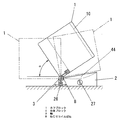
以下、本発明を添付図面に示す実施形態に基いて説明すると、図1において、1はカフ帯及び該カフ帯を上腕に巻き付けるための後述する巻き付け機構を内蔵したカフブロックであり、上腕を挿通するための挿通口10が貫通する筒状となっている。このカフブロック1は、机上などに載置される台座ブロック2に対して軸3によって回動自在に連結されることで、水平面に対する角度が可変となっている。また、上記軸3の付近には一端をカフブロック1側に固定し且つ他端を台座ブロック2側に固定したねじりコイルばね8を配設してある。
Hereinafter, the present invention will be described with reference to an embodiment shown in the accompanying drawings. In FIG. 1,
上記ねじりコイルばね8は、カフブロック1の角度に応じて付勢方向を変更するもので、カフブロック1の自重との関係で、常時はカフブロック1を水平面に対して所定の角度αをなす状態に保つものであり、この角度αより小さい角度や大きい角度となるようにカフブロック1を動かしても、カフブロック1に加えた力を緩めれば、カフブロック1は上記角度αにばね付勢によって自動復帰する。
The torsion coil spring 8 changes the urging direction according to the angle of the
ここにおける上記の所定角度αは、30°から45°の範囲内の角度であることが好ましいが、この範囲内に限定するものではない。また、変更することができるカフブロック1の角度範囲は、上記角度範囲を完全に包含する範囲、たとえば0°〜90°程度であることが望ましい。
Here, the predetermined angle α is preferably an angle within a range of 30 ° to 45 °, but is not limited to this range. Moreover, it is desirable that the angle range of the
このものにおいては、カフブロック1は通常時、上記角度αを保っているために、カフブロック1への腕への挿入に際して予め上記角度を変更する必要は全くなく、そのまま腕を挿通口10に差し込んでいけばよく、しかも腕を挿通口10に差し入れていけば、カフブロック1は腕の角度に応じて角度を変化させるものであり、最終的には挿通口10に通した上腕と水平面となす角度と一致する角度となる。
In this case, since the
また血圧測定して終了する時も、そのまま腕を引き抜けば、カフブロック1は腕の角度に追従して角度を変化させるために、腕がカフブロック1に引っ掛かったりすることなく、腕を抜き出せるものであり、また腕を抜き出した後は、カフブロック1は上記角度αを維持する。
Also, when the blood pressure measurement is finished, if the arm is pulled out as it is, the
なお、カフブロック1に腕を通すにあたっては、カフブロック1を手前側に大きく倒してほぼ水平状態とし、この状態で前腕部を差し入れるという動作も可能である。この時も、肘位置よりも上腕側が挿通口10内に入る時には、カフブロック1は腕の角度に追従して立ち上がるために、途中でカフブロック1の角度を手動変更する必要はない。
When passing the arm through the
台座ブロック1を置く机の高さや被験者の体格差によっては、上記所定の角度αがあまり適切ではない場合も存在することから、たとえばねじりコイルばね8の台座ブロック2側の端部を台座ブロック2に固定している固定部26を図中左右方向に調節することでカフブロック1に対するばね力を変化させる調節ダイアル27を設けておくとよい。この調節ダイアル27による上記調整で、所定の角度αを調整することができる。
Depending on the height of the desk on which the
なお、収納時や運搬時には、カフブロック1が台座ブロック2に対して回動できない状態にある方が好ましいことから、図2に示すように台座ブロック1に対してカフブロック1を固定しまうロック手段85を設けておくことが好ましい。
Since it is preferable that the
図3は上記カフブロック1内の巻き取り機構を示しており、図中11はカフ帯、12は巻き取りドラム、13はギアモータ、14は減速輪列であり、ギアモータ13の減速輪列14を介した巻き取りドラム12の回転でカフ帯11の巻き取り及び巻き戻し動作がなされる。
FIG. 3 shows a winding mechanism in the
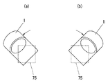
なお、上記ギアモータ13及び減速輪列14は、図3(a)に示すように、軸3が位置する一端側と反対側の端部に配置した時、軸3付近を通る配管や配線の配置が容易となるとともに、台座ブロック2の軸3付近を小型に保つことができるが、図3(b)に示すように、重量物であるギアモータ13及び減速輪列14を軸3付近に配置すれば、カフブロック1を回動させるのに必要なトルクが小さくてすむために、ねじりコイルばね8も小さなもので済むものとなる。
As shown in FIG. 3A, when the
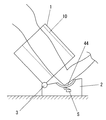
ところで台座ブロック2の上面には、カフブロック1に通した腕の肘の部分を受ける肘置き部44を設けて、この肘置き部44に肘を置くことで上腕に対するカフブロック1の位置決めがなされるようにしているのであるが、この肘置き部44には図4に示すように肘が置かれたかどうかを検出するスイッチSを設けて、血圧測定を開始させるにあたり、このスイッチSがオンになっていなければ警告音や警告表示が出るようにしたり、あるいはスイッチSがオンとなることで、血圧測定動作が開始されるようにしておくと、カフブロック1に上腕が十分に差し込まれていない状態での血圧測定がなされてしまうような事態が生じるのを防ぐことができる。
By the way, on the upper surface of the
また、カフブロック1を台座ブロック2に回動自在に連結しているとともに台座ブロック2上に肘の位置決めのための部分を設けるにあたっては、図5に示すように、肘位置の位置決め用の肘置き部44と、前腕を支えることになる前腕サポート部45とを備えた肘置きブロック4を台座ブロック2の上面にスライド自在に配設するとともに、この肘置きブロック4の一端を上記カフブロック1の軸3から少し離れたところに支軸40によって連結し、台座ブロック2に対してカフブロック1を回動させたならば、肘置きブロック4がカフブロック1の回動角度に応じて台座ブロック2上の位置を変更するようにしておくことが好ましい。
Further, when the
カフブロック1の挿通口10に上腕9を挿通した血圧測定被験者の背が高くて(あるいは台座ブロック2が置かれた面の高さが低くて)、カフブロック1と水平面とのなす角度(カフブロック1の傾斜角度)γが大きい時、肘置きブロック4は上記軸3から離れたところに位置し、逆に血圧測定被験者の背が低くて(あるいは台座ブロック2が置かれた面の高さが高くて)、カフブロック1と水平面とのなす角度(カフブロック1の傾斜角度)γが小さい時には、肘置きブロック4は上記軸3に寄ったところに位置することになり、肘置きブロック4における肘位置の位置決め用の肘置き部44からカフブロック1内のカフ帯までの距離は、カフブロック1の傾斜角度に拘わらず、ほぼ一定に保たれる。このために常に正確な血圧測定を行うことができるものとなる。
The blood pressure measurement subject who has inserted the
なお、上記肘置きブロック4は台座ブロック2に設けられたガイド溝21に沿って摺動するガイド軸41を備えている。このガイド溝21は、上記軸3寄りの一端よりも他端側の方が低い位置にくる円弧状のもの(斜め直線状であってもよい)としてあるが、これはカフブロック1の回動に伴う肘置きブロック4の上記前後動が、肘置きブロック4の傾斜角度θをほぼ一定に保った状態でなされるようにしているためであり、角度θが変化してもよい場合は、ガイド溝21を水平な溝として形成すればよい。
The elbow rest block 4 includes a
図6以降に示すものは、台座ブロック2に対して、カフブロック1の水平面上の位置及び鉛直軸回りの向きを変化させることができるようにしたもので、台座ブロック2の上面には十字状の溝70を設けてある。また、前記軸3の台座ブロック2側の軸受けを備える可動ベース71を設けて、この可動ベース71が備える軸部72を上記溝70内に位置させている。上記軸部72は、溝70の幅とほぼ等しい外径であり、この軸部72を十字状の溝70に沿って動かすことで、水平面上でのカフブロック1の位置を前後左右に動かすことができ、更に可動ベース71の軸部72をその軸回りに回転させることで、図7に示すように鉛直軸回りの向きを変化させることができる。
In FIG. 6 and subsequent figures, the position of the
このために、台座ブロック2と被験者の肩位置とが正対していない状態でも、被験者の腕の位置や向きに応じてカフブロック2の位置や向きを変化させることができるものであり、このために腕を楽な状態に保ったまま血圧測定を行うことができる。
For this reason, the position and orientation of the
また、上記十字状の溝70を台座ブロック2に直接設けるのではなく、台座ブロック2に対して上下(鉛直方向)に位置を変化させることができるシフトベース75を設けて、このシフトベース75に上記溝70を設ければ、カフブロック1の鉛直方向位置の調整も行うことができて、更に楽な姿勢での血圧測定が可能となる。
In addition, the
なお、血圧の測定開始後は、カフブロック1が動きまわっては測定精度に問題が生じることから、上記の可動構成については少なくとも可動ベース71の動きを阻止することができるロック手段(図示せず)を設けておくことが好ましい。また、カフブロック1の水平面上での位置及び鉛直軸回りの向きを変化させることは、カフブロック1を軸3の回りに回動自在としていないものにおいても測定時の姿勢を楽にするという点で有効である。
After the blood pressure measurement is started, if the
1 カフブロック
2 台座ブロック
3 軸
8 ねじりコイルばね
1
Claims (7)
Priority Applications (7)
| Application Number | Priority Date | Filing Date | Title |
|---|---|---|---|
| JP2006337375A JP4830833B2 (en) | 2006-12-14 | 2006-12-14 | Sphygmomanometer |
| DE602007003429T DE602007003429D1 (en) | 2006-12-14 | 2007-12-12 | sphygmomanometer |
| EP07024132A EP1932468B1 (en) | 2006-12-14 | 2007-12-12 | Sphygmomanometer |
| AT07024132T ATE449564T1 (en) | 2006-12-14 | 2007-12-12 | SPHYGMOMANOMETER |
| US12/000,478 US8109881B2 (en) | 2006-12-14 | 2007-12-13 | Sphygmomanometer |
| CNU2007201820427U CN201153942Y (en) | 2006-12-14 | 2007-12-13 | Sphygmomanometer |
| CN2007101995341A CN101229059B (en) | 2006-12-14 | 2007-12-13 | Sphygmomanometer |
Applications Claiming Priority (1)
| Application Number | Priority Date | Filing Date | Title |
|---|---|---|---|
| JP2006337375A JP4830833B2 (en) | 2006-12-14 | 2006-12-14 | Sphygmomanometer |
Publications (2)
| Publication Number | Publication Date |
|---|---|
| JP2008148765A JP2008148765A (en) | 2008-07-03 |
| JP4830833B2 true JP4830833B2 (en) | 2011-12-07 |
Family
ID=39171379
Family Applications (1)
| Application Number | Title | Priority Date | Filing Date |
|---|---|---|---|
| JP2006337375A Expired - Fee Related JP4830833B2 (en) | 2006-12-14 | 2006-12-14 | Sphygmomanometer |
Country Status (6)
| Country | Link |
|---|---|
| US (1) | US8109881B2 (en) |
| EP (1) | EP1932468B1 (en) |
| JP (1) | JP4830833B2 (en) |
| CN (2) | CN201153942Y (en) |
| AT (1) | ATE449564T1 (en) |
| DE (1) | DE602007003429D1 (en) |
Families Citing this family (15)
| Publication number | Priority date | Publication date | Assignee | Title |
|---|---|---|---|---|
| JP4830833B2 (en) * | 2006-12-14 | 2011-12-07 | パナソニック電工株式会社 | Sphygmomanometer |
| JP2010075514A (en) * | 2008-09-26 | 2010-04-08 | Omron Healthcare Co Ltd | Measuring instrument for blood pressure information |
| JP5182025B2 (en) * | 2008-11-10 | 2013-04-10 | オムロンヘルスケア株式会社 | Blood pressure measurement device |
| JP5200953B2 (en) * | 2009-01-22 | 2013-06-05 | オムロンヘルスケア株式会社 | Blood pressure measurement device |
| JP5313735B2 (en) * | 2009-03-24 | 2013-10-09 | テルモ株式会社 | Electronic blood pressure monitor |
| JP5287572B2 (en) | 2009-07-23 | 2013-09-11 | オムロンヘルスケア株式会社 | Sphygmomanometer |
| JP2011255009A (en) * | 2010-06-09 | 2011-12-22 | A & D Co Ltd | Blood pressure measuring apparatus having rack |
| JP2012200508A (en) * | 2011-03-28 | 2012-10-22 | Omron Healthcare Co Ltd | Cuff for blood pressure information measuring device and blood pressure information measuring device having the same |
| US20140350418A1 (en) * | 2013-05-21 | 2014-11-27 | Pharma-Smart Internation, Inc. | Blood pressure kiosk for use with left or right arm |
| US10271743B2 (en) * | 2014-05-27 | 2019-04-30 | Higi Sh Llc | System for facilitating measurement of a person's blood pressure and method of taking a blood pressure measurement using the system |
| CN104434074B (en) * | 2014-12-24 | 2017-08-04 | 深圳瑞光康泰科技有限公司 | Automated blood pressure device |
| KR101954990B1 (en) * | 2016-07-15 | 2019-03-07 | 주식회사 인바디 | Appratus for measuring blood pressure |
| US10709340B2 (en) | 2016-12-30 | 2020-07-14 | Higi Sh Llc | Automated fitted cuff blood pressure and arm circumference measuring device |
| JP7070022B2 (en) * | 2018-04-20 | 2022-05-18 | オムロンヘルスケア株式会社 | Sphygmomanometer |
| KR102075943B1 (en) * | 2019-02-27 | 2020-02-12 | 주식회사 인바디 | Appratus for measuring blood pressure |
Family Cites Families (13)
| Publication number | Priority date | Publication date | Assignee | Title |
|---|---|---|---|---|
| US3935984A (en) * | 1974-09-09 | 1976-02-03 | Ambitex Company | Automatic cuff mechanism for blood pressure measuring system |
| JPS5618839A (en) * | 1979-07-23 | 1981-02-23 | Fuji Electric Co Ltd | Cuff mounting base movable mechanism for cuff automatic winder |
| JPS57180939A (en) * | 1981-04-30 | 1982-11-08 | Fuji Denki Sogo Kenkyusho Kk | Cuff automatic take-up apparatus |
| JPH01254145A (en) * | 1988-04-04 | 1989-10-11 | Omron Tateisi Electron Co | Electronic tonometer |
| JPH04218729A (en) * | 1990-11-27 | 1992-08-10 | Toray Ind Inc | Electric weight meter with automatic haemadynamometer |
| JPH04217829A (en) | 1990-12-18 | 1992-08-07 | Ishikawajima Harima Heavy Ind Co Ltd | Power switch for automatic start/stop machine |
| US6045510A (en) * | 1994-02-25 | 2000-04-04 | Colin Corporation | Blood pressure measuring apparatus |
| JP4016512B2 (en) * | 1998-12-01 | 2007-12-05 | オムロンヘルスケア株式会社 | Blood pressure measurement stand with automatic height adjustment function |
| JP3966188B2 (en) | 2003-02-26 | 2007-08-29 | 松下電工株式会社 | Sphygmomanometer |
| KR100679972B1 (en) * | 2004-02-24 | 2007-02-08 | 마츠시다 덴코 가부시키가이샤 | Sphygmomanometer |
| JP3818295B2 (en) * | 2004-02-27 | 2006-09-06 | オムロンヘルスケア株式会社 | Blood pressure measurement device |
| JP2006000337A (en) * | 2004-06-17 | 2006-01-05 | Omron Healthcare Co Ltd | Electronic blood pressure monitor |
| JP4830833B2 (en) * | 2006-12-14 | 2011-12-07 | パナソニック電工株式会社 | Sphygmomanometer |
-
2006
- 2006-12-14 JP JP2006337375A patent/JP4830833B2/en not_active Expired - Fee Related
-
2007
- 2007-12-12 AT AT07024132T patent/ATE449564T1/en not_active IP Right Cessation
- 2007-12-12 EP EP07024132A patent/EP1932468B1/en not_active Not-in-force
- 2007-12-12 DE DE602007003429T patent/DE602007003429D1/en active Active
- 2007-12-13 US US12/000,478 patent/US8109881B2/en not_active Expired - Fee Related
- 2007-12-13 CN CNU2007201820427U patent/CN201153942Y/en not_active Expired - Fee Related
- 2007-12-13 CN CN2007101995341A patent/CN101229059B/en active Active
Also Published As
| Publication number | Publication date |
|---|---|
| US20080146950A1 (en) | 2008-06-19 |
| CN101229059B (en) | 2010-12-08 |
| EP1932468A3 (en) | 2008-08-13 |
| DE602007003429D1 (en) | 2010-01-07 |
| ATE449564T1 (en) | 2009-12-15 |
| EP1932468B1 (en) | 2009-11-25 |
| CN101229059A (en) | 2008-07-30 |
| CN201153942Y (en) | 2008-11-26 |
| JP2008148765A (en) | 2008-07-03 |
| US8109881B2 (en) | 2012-02-07 |
| EP1932468A2 (en) | 2008-06-18 |
Similar Documents
| Publication | Publication Date | Title |
|---|---|---|
| JP4830833B2 (en) | Sphygmomanometer | |
| US7913537B2 (en) | Adjustment device for a measuring head | |
| US7735237B1 (en) | Versatile caliper mounting and measurement accessory | |
| US7197835B2 (en) | Detector supporting mechanism | |
| US6769657B1 (en) | Support device for monitor, display or objects | |
| JP2003513259A (en) | Measuring device with movable measuring probe | |
| US8336223B2 (en) | Roundness measuring apparatus | |
| US7950164B2 (en) | Surface texture measurement apparatus and roundness measuring apparatus | |
| JP4830832B2 (en) | Sphygmomanometer | |
| JP2013542630A (en) | Ball joint type support head for video photographic equipment | |
| JP5000894B2 (en) | Surface texture measuring machine | |
| US11204296B2 (en) | Horizontal instrument, a supporting device and a method for adjusting the bearing surface of the supporting device to be horizontal | |
| JP2008215624A (en) | Stand which has energy accumulating section for tare weight balance | |
| JP5611333B2 (en) | Pipe bending machine | |
| US6722050B2 (en) | Bend-angle measuring device | |
| US20070044614A1 (en) | Sawing machine | |
| JP3959319B2 (en) | Detector for surface texture measuring machine | |
| JP3875443B2 (en) | Surveying pole and GPS surveying mobile station antenna holding device | |
| JPH1123437A (en) | Method and equipment for measuring flexural rigidity of rod-like material | |
| JP2000041958A (en) | Automatic sphygmomanometry instrument | |
| RU2003116171A (en) | METHOD AND DEVICE FOR CENTERING GLASS FLOW CONTROL PIPE | |
| JP2008082923A (en) | Retainer of pole for measurement, or the like | |
| JP2001116543A (en) | Posture controller |
Legal Events
| Date | Code | Title | Description |
|---|---|---|---|
| A621 | Written request for application examination |
Free format text: JAPANESE INTERMEDIATE CODE: A621 Effective date: 20090312 |
|
| RD04 | Notification of resignation of power of attorney |
Free format text: JAPANESE INTERMEDIATE CODE: A7424 Effective date: 20100902 |
|
| A977 | Report on retrieval |
Free format text: JAPANESE INTERMEDIATE CODE: A971007 Effective date: 20110519 |
|
| A131 | Notification of reasons for refusal |
Free format text: JAPANESE INTERMEDIATE CODE: A131 Effective date: 20110531 |
|
| A521 | Request for written amendment filed |
Free format text: JAPANESE INTERMEDIATE CODE: A523 Effective date: 20110801 |
|
| TRDD | Decision of grant or rejection written | ||
| A01 | Written decision to grant a patent or to grant a registration (utility model) |
Free format text: JAPANESE INTERMEDIATE CODE: A01 Effective date: 20110823 |
|
| A01 | Written decision to grant a patent or to grant a registration (utility model) |
Free format text: JAPANESE INTERMEDIATE CODE: A01 |
|
| A61 | First payment of annual fees (during grant procedure) |
Free format text: JAPANESE INTERMEDIATE CODE: A61 Effective date: 20110905 |
|
| R151 | Written notification of patent or utility model registration |
Ref document number: 4830833 Country of ref document: JP Free format text: JAPANESE INTERMEDIATE CODE: R151 |
|
| FPAY | Renewal fee payment (event date is renewal date of database) |
Free format text: PAYMENT UNTIL: 20140930 Year of fee payment: 3 |
|
| LAPS | Cancellation because of no payment of annual fees |


