JP4830552B2 - Face milling - Google Patents

Face milling Download PDF

Info

Publication number
JP4830552B2
JP4830552B2 JP2006065033A JP2006065033A JP4830552B2 JP 4830552 B2 JP4830552 B2 JP 4830552B2 JP 2006065033 A JP2006065033 A JP 2006065033A JP 2006065033 A JP2006065033 A JP 2006065033A JP 4830552 B2 JP4830552 B2 JP 4830552B2
Authority
JP
Japan
Prior art keywords
cutting edge
tip
rough machining
main cutting
chip
Prior art date
Legal status (The legal status is an assumption and is not a legal conclusion. Google has not performed a legal analysis and makes no representation as to the accuracy of the status listed.)
Active
Application number
JP2006065033A
Other languages
Japanese (ja)
Other versions
JP2007237356A (en
Inventor
和俊 富松
一成 川端下
浩教 近藤
可薫 山田
Current Assignee (The listed assignees may be inaccurate. Google has not performed a legal analysis and makes no representation or warranty as to the accuracy of the list.)
Tungaloy Corp
Original Assignee
Tungaloy Corp
Priority date (The priority date is an assumption and is not a legal conclusion. Google has not performed a legal analysis and makes no representation as to the accuracy of the date listed.)
Filing date
Publication date
Application filed by Tungaloy Corp filed Critical Tungaloy Corp
Priority to JP2006065033A priority Critical patent/JP4830552B2/en
Publication of JP2007237356A publication Critical patent/JP2007237356A/en
Application granted granted Critical
Publication of JP4830552B2 publication Critical patent/JP4830552B2/en
Active legal-status Critical Current
Anticipated expiration legal-status Critical

Links

Images

Landscapes

  • Milling Processes (AREA)

Description

本発明は、粗加工と仕上げ加工を同時に行う正面フライスに関し、特に送り量を高めた高能率加工が可能であるとともに仕上げ面の表面あらさが向上した正面フライスに関するものである。   The present invention relates to a face mill that performs roughing and finishing simultaneously, and more particularly to a face mill that enables high-efficiency machining with an increased feed amount and improved surface roughness of the finished surface.

被削材を平面加工する正面フライスにおいて、粗加工と仕上げ加工を同時に行う、いわゆるコンビネーション式正面フライスの従来例を図9〜図11に図示する。図9に図示したコンビネーション式正面フライスは、環状体をなす正面フライス本体1の正面部分で、中央取付穴13の利用により固定され、しかも、その正面切刃19が本体1の中心線に対し、略直角の関係にあるように、1個または、数個等配されたさらい刃チップ12と、正面側のさらい刃チップ12の占める部分を除外するようにして、外周切刃が構成される多数の粗刃チップ3の正面切刃より幾分凸出する位置関係にあり、本体の回転方向を基準にとって、さらい刃チップ12が1個のときには、全体を1つのグループとし、また、さらい刃チップ12が数個のときには、さらい刃チップ12の次にくる粗刃チップ3から、次のさらい刃チップ12の1つ前の粗刃チップ3までを1つのグループとして、さらい刃チップ12の数に等しいグループを構成し、それぞれのグループに属する粗刃チップn個に対し、さらい刃チップ12を挟む粗刃チップ3間が、他の粗刃チップ3間よりも幾分広くなるように、他の粗刃チップ3間を等分割し、さらに粗刃チップ3について、軸心から刃先先端までの半径方向の距離X1〜Xnを位置的に補正することにより粗刃チップ3に略等しい切削送りが補償されるようにしたものである(例えば、特許文献1参照)。 9 to 11 show conventional examples of so-called combination type face milling, in which roughing and finishing are simultaneously performed in a face milling machined with a workpiece. The combination type front milling machine illustrated in FIG. 9 is fixed by using the central mounting hole 13 at the front part of the front milling body 1 that forms an annular body, and the front cutting edge 19 is fixed to the center line of the main body 1. A number of outer peripheral cutting edges are configured so as to exclude a portion occupied by one or several equally arranged wiping blade tips 12 and the wiping blade tip 12 on the front side so as to have a substantially right angle relationship. The rough cutting edge tip 3 has a positional relationship that protrudes somewhat from the front cutting edge. When the number of the cutting edge chips 12 is one with respect to the rotation direction of the main body, the entire cutting edge is formed into one group. When the number 12 is several, the number from the coarse blade tip 3 next to the wiper blade tip 12 to the coarse blade tip 3 immediately before the next wiper blade tip 12 is grouped into one group. Other groups so that the gap between the coarse edge chips 3 sandwiching the wiper edge chip 12 is somewhat wider than that between the other coarse edge chips 3 for n coarse edge chips belonging to each group. The coarse feed tip 3 is equally divided, and the coarse feed tip 3 is further corrected by cutting the radial distances X 1 to X n from the axial center to the tip of the blade tip to substantially equal the coarse feed tip 3 cutting feed. Is compensated for (see, for example, Patent Document 1).

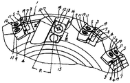
図10に図示したさらい刃付き正面フライスは、軸心を中心にして回転せしめられるフライス本体1の下面周縁部に主切削チップ21およびさらい刃チップ22が設けられ、上記主切削チップ21は、上記フライス本体1の外周側に位置する主切刃26と、この主切刃26の下端に形成された面取りコーナ27と、この面取りコーナ27から上記フライス本体1の軸心側に向かうにしたがって上方に傾斜された逃げ部28bとを有するものであり、上記さらい刃チップ22は、上記フライス本体1の外周側に位置する主切刃29と、この主切刃29の下端に形成された面取りコーナ30と、この面取りコーナ30から上記フライス本体1の軸心側に延び送り方向に略平行な副切刃31とを有するものである(例えば、特許文献2参照)。 10 is provided with a main cutting tip 21 and a wiping blade tip 22 at the peripheral edge of the lower surface of the milling body 1 that is rotated about an axis, and the main cutting tip 21 is A main cutting edge 26 located on the outer peripheral side of the milling body 1, a chamfered corner 27 formed at the lower end of the main cutting edge 26, and upward from the chamfering corner 27 toward the axial center side of the milling body 1. The sieving edge tip 22 has a main cutting edge 29 located on the outer peripheral side of the milling body 1 and a chamfered corner 30 formed at the lower end of the main cutting edge 29. And a sub-cutting blade 31 extending from the chamfered corner 30 to the axial center side of the milling body 1 and substantially parallel to the feed direction (see, for example, Patent Document 2).

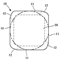
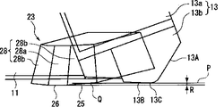
図11に図示したスローアウェイ式カッターは、軸線O回りに回転される略円盤状のカッター本体11の先端外周部に、正面刃13Bを備えたチップ13が着脱可能に装着されるとともに、このカッター本体11の先端部の上記チップ13よりも内周側には、さらい刃25を備えたさらい刃チップ23が、このさらい刃25を上記正面刃13Bの最先端を通って上記軸線Oに直交する平面Pよりも先端側に突出させて着脱可能に装着されてなるカッターにおいて、上記さらい刃25を、上記カッター本体11の外周側に向かうに従い後端側に向けて傾斜させて上記平面Pと交差するように配設したものである(例えば、特許文献3参照)。 In the throw-away cutter shown in FIG. 11, a tip 13 having a front blade 13B is detachably mounted on the outer periphery of the distal end of a substantially disc-shaped cutter body 11 rotated about an axis O. On the inner peripheral side of the tip portion of the main body 11 with respect to the tip 13, a wiping blade tip 23 provided with a wiping blade 25 passes through the forefront of the front blade 13B and is perpendicular to the axis O. In a cutter that is detachably mounted by projecting toward the front end side with respect to the plane P, the wiper blade 25 is inclined toward the rear end side toward the outer peripheral side of the cutter body 11 and intersects with the plane P. (See, for example, Patent Document 3).

特開昭50−49790号公報Japanese Patent Laid-Open No. 50-49790 実開平3−71812号公報Japanese Utility Model Publication No. 3-71812 特開2002−192415号公報JP 2002-192415 A

しかしながら、上記特許文献1の発明においては、切削送りを補償するにあたり想定した切削送りを大幅に超えた高送り加工を行った場合、粗刃チップ3の送りが総じて大きくなり且つ不均等になるため、粗刃チップの主切刃にチッピングや欠損が生じて短寿命となる問題があった。また、加工時の振動が大きくなるため、仕上げ面あらさが悪化する問題があった。   However, in the invention of the above-mentioned Patent Document 1, when high feed processing that greatly exceeds the cutting feed assumed in compensating the cutting feed is performed, the feed of the rough blade tip 3 becomes generally large and uneven. There is a problem that chipping or chipping occurs in the main cutting edge of the coarse blade tip, resulting in a short life. Further, since the vibration during processing becomes large, there is a problem that the roughness of the finished surface is deteriorated.

上記特許文献2の発明においても、切削送りを比較的大きくした高送り加工を行った場合、正面フライス本体1の振動が大きくなることから、さらい刃チップ21の副切刃により切削面の送りマークをきれいに取り除くことができなくなり、該切削面の表面あらさが悪化する問題があった。さらに、さらい刃チップ12の主切刃の回転軌跡が主切削チップの主切刃の回転軌跡と同一位置になるように形成した場合には、さらい刃チップ12に大きな切削抵抗が作用するため、切削面の表面あらさがいっそう悪化する問題があった。   Also in the invention of the above-mentioned Patent Document 2, when high feed machining with relatively large cutting feed is performed, the vibration of the face milling body 1 becomes large. Cannot be removed cleanly, and the surface roughness of the cutting surface deteriorates. Furthermore, when the rotation locus of the main cutting edge of the wiping blade tip 12 is formed so as to be in the same position as the rotation locus of the main cutting edge of the main cutting tip, a large cutting resistance acts on the wiping blade tip 12, There was a problem that the surface roughness of the cutting surface worsened further.

上記特許文献3の発明においては、切削送りを大きくした高送り加工を行った場合、チップ13の主切刃及びさらい刃チップ23のさらい刃25と上記平面Pの交点には、大きい切削抵抗が作用するため欠損や摩耗が発生しやすくなり、これらチップ13及びさらい刃チップ23が短寿命となる問題があった。   In the invention of the above-mentioned Patent Document 3, when high feed processing with a large cutting feed is performed, a large cutting resistance is present at the intersection of the main cutting edge of the tip 13 and the wiping edge 25 of the wiping edge tip 23 and the plane P. Since it acts, it becomes easy to generate | occur | produce a defect | deletion and abrasion, and there existed a problem that these tips 13 and the wiping edge tip 23 became short life.

本発明は、上記問題を解決するためになされたもので、送り量を大きくした高能率加工を可能とするとともに、仕上げ面の表面あらさの向上を可能とする、正面フライスを提供することを目的とする。さらに、上記正面フライスに装着されるスローアウェイチップの経済性を高めることも目的としている。   The present invention has been made to solve the above problems, and an object of the present invention is to provide a face mill that enables high-efficiency machining with a large feed amount and improves the surface roughness of the finished surface. And It is another object of the present invention to improve the economics of the throw-away tip attached to the face mill.

上記課題を解決するために、本発明は以下の構成を採用する。軸心CLまわりに回転させられる工具本体2の先端外周部に、複数の粗加工用チップ10が着脱可能に装着されるとともに、上記工具本体2の先端外周部の上記粗加工用チップ10より上記軸心CL側には、さらい刃21を備えた少なくとも1つの仕上げ加工用チップ20が着脱可能に装着されてなる正面フライスにおいて、上記粗加工用チップ10は、略正多角形板状をなし、その正多角形面の少なくとも一方に形成されたすくい面14が工具回転方向Kに向き、上記正多角形面の稜辺部に形成された直線状又は曲線状をなす主切刃11が上記工具本体2の外周面3から突出し、上記主切刃11のアプローチ角ψが60°〜80°の範囲内にあり、上記正多角形面のコーナ部に形成された副切刃12が上記軸心CLに対して略直角に延びるように配設され、上記仕上げ用チップ20は、略正多角形板状をなし、その正多角形面の少なくとも一方に形成されたすくい面24が工具回転方向Kに向き、上記正多角形面の稜辺部に形成された主切刃21が上記工具本体2の先端外周部に配され、上記正多角形面の少なくとも1つのコーナ部に形成された直線状又は曲線状をなすさらい刃22が上記軸心CLに対して略直角に延びるように配設され、さらに、上記仕上げ加工用チップ20のさらい刃22が上記粗加工用チップ10の副切刃12より工具先端部側に突出させられたことを特徴とする。   In order to solve the above problems, the present invention employs the following configuration. A plurality of rough machining tips 10 are detachably attached to the outer periphery of the tip of the tool body 2 rotated around the axis CL, and the above-mentioned rough machining tips 10 on the outer periphery of the tip of the tool body 2 In the face mill in which at least one finishing tip 20 having a wiping blade 21 is detachably mounted on the axis CL side, the roughing tip 10 has a substantially regular polygonal plate shape, The rake face 14 formed on at least one of the regular polygonal surfaces is directed in the tool rotation direction K, and the main cutting edge 11 having a linear or curved shape formed on the ridge side of the regular polygonal surface is the tool. Projecting from the outer peripheral surface 3 of the main body 2, the approach angle ψ of the main cutting edge 11 is in the range of 60 ° to 80 °, and the auxiliary cutting edge 12 formed at the corner portion of the regular polygonal surface is the axis. It extends almost perpendicular to CL The finishing chip 20 has a substantially regular polygonal plate shape, the rake face 24 formed on at least one of the regular polygonal surfaces is directed in the tool rotation direction K, A main cutting edge 21 formed on the ridge side is arranged on the outer periphery of the tip of the tool body 2, and a straight or curved wiping blade 22 formed on at least one corner of the regular polygonal surface is provided. It is arranged so as to extend substantially perpendicular to the axis CL, and further, the wiping blade 22 of the finishing chip 20 is projected from the auxiliary cutting edge 12 of the roughing chip 10 to the tool tip side. It is characterized by that.

以上の構成を有する正面フライス1は、粗加工用チップ10のアプローチ角ψが60°〜80°の範囲となるように配設されていることから、該粗加工用チップ10の主切刃11の切取り厚さが従来正面フライスより小さくなり、上記主切刃11の各位置における切削抵抗が比較的小さくなるため、送り量を大きくした高能率な正面削りにおいても該正面フライス1及び被削材のびびり振動を抑制するとともに粗加工用チップ10のチッピングや欠損の発生を防止する。   Since the front milling cutter 1 having the above configuration is arranged so that the approach angle ψ of the rough machining tip 10 is in the range of 60 ° to 80 °, the main cutting edge 11 of the rough machining tip 10 is arranged. Since the cutting thickness is smaller than that of a conventional face mill and the cutting resistance at each position of the main cutting edge 11 is relatively small, the face mill 1 and the work material can be used even in highly efficient face milling with a large feed amount. It suppresses chatter vibration and prevents chipping or chipping of the rough machining tip 10.

さらに、仕上げ加工用チップ20は、その直線状又は曲線状をなすさらい刃22が上記軸心CL方向と略直角に延び且つ上記粗加工用チップ10の副切刃12より工具先端部側に突出して配設されているので、粗加工用チップ10による切削面を仕上げ切削し、その仕上げ面の表面あらさを向上させる。特に、送り量を大きくした高能率な正面削りにおいて、上述のとおり正面フライス1及び被削材のびびり振動が抑えられるので、仕上げ面の表面あらさが大幅に向上する。   Further, the finish machining tip 20 has a straight or curved wiping blade 22 extending substantially at right angles to the direction of the axis CL and protruding from the auxiliary cutting edge 12 of the rough machining tip 10 toward the tool tip. Therefore, the cutting surface by the rough machining tip 10 is finish-cut to improve the surface roughness of the finishing surface. Particularly, in high-efficiency face cutting with a large feed amount, chatter vibrations of the face mill 1 and the work material can be suppressed as described above, so that the surface roughness of the finished surface is greatly improved.

上記正面フライス1において、上記粗加工用チップ10の正多角形面の少なくとも1つのコーナ部には、上記副切刃12と、該副切刃12の内周側に連なり且つ上記軸心CL側に向かうにつれ工具基端部側に向かって傾斜する第2副切刃13が形成され、上記副切刃12と上記第2副切刃13が上記コーナ部の2等分線Bを基準として対称形状とされた場合には、正回転用正面フライス1及び逆回転用正面フライス1´にそれぞれ装着されたとき、それぞれの切刃の該正面フライス1、1´の軸心CLまわりの回転軌跡が等しくなる。よって、1個当たり使用コーナ数が2倍に増し経済性が向上する。さらに、上記正多角形面の全てのコーナ部に、上記副切刃12及び上記第2副切刃13を上記コーナ部の2等分線Bを基準として対称形状となるように形成すると、上記経済性の点で最も有効となる。 In the face mill 1, at least one corner portion of the regular polygonal surface of the rough machining tip 10 is connected to the auxiliary cutting edge 12 and the inner peripheral side of the auxiliary cutting edge 12, and the axis CL side. A second secondary cutting edge 13 that is inclined toward the tool base end side is formed as it goes toward the center, and the secondary cutting edge 12 and the second secondary cutting edge 13 are symmetrical with respect to the bisector B of the corner portion. In the case of the shape, when mounted on the forward rotation front milling cutter 1 and the reverse rotation front milling cutter 1 ′, the rotation trajectory around the axis CL of the front milling cutter 1, 1 ′ of each cutting blade is obtained. Will be equal. Therefore, the number of corners used per unit is doubled and the economy is improved. Furthermore, when the secondary cutting edge 12 and the second secondary cutting edge 13 are formed in all corner portions of the regular polygonal surface so as to be symmetrical with respect to the bisector B of the corner portion, Most effective in terms of economy.

さらに、上記正面フライスにおいて、上記仕上げ加工用チップ20の正多角形面の全てのコーナ部に、該コーナ部の2等分線Bに対して略直角に延びるさらい刃22が形成された場合には、仕上げ加工用チップ20の使用コーナ数が増し経済性が高くなる。 Further, in the above face mill, when all the corner portions of the regular polygonal surface of the finishing chip 20 are formed with the wiping blades 22 extending substantially perpendicular to the bisector B of the corner portion. This increases the number of corners used for the finishing chip 20 and increases the economic efficiency.

さらに、上記粗加工用チップ10の上記正多角形面の稜辺に内接する内接円の直径が15mm以上とした場合には、該粗加工用チップ10の主切刃11は、粗加工において充分な切込みを確保し、該粗加工用チップ10は、工具本体2に装着する際において、上記工具本体2に衝合する上記主切刃11から延びる側面の該主切刃11方向の長さを充分に確保することができ、高精度且つ安定的に装着される。なお、上記内接円の直径が30mmを超えると、粗加工用チップ10の大型化により不経済となる。仕上げ加工用チップ20の正多角形面の稜辺に内接する内接円の直径を15mm以上とした場合には、コーナ部に形成されたさらい刃22は、そのさらい刃22方向の長さを充分に長く形成することができ、高送り時の表面あらさの向上に寄与するとともに、工具本体2に保持される上記正多角形面の稜辺部に形成された主切刃21から延びる側面の面積を充分に確保することができ、該仕上げ加工用チップ20は工具本体2に高精度且つ安定的に装着される。   Further, when the diameter of the inscribed circle inscribed in the edge of the regular polygonal surface of the rough machining tip 10 is 15 mm or more, the main cutting edge 11 of the rough machining tip 10 is used for rough machining. A sufficient depth of cut is ensured, and when the rough machining tip 10 is mounted on the tool body 2, the length in the direction of the main cutting edge 11 of the side surface extending from the main cutting edge 11 that abuts the tool body 2 is secured. Can be secured sufficiently and can be mounted with high accuracy and stability. If the diameter of the inscribed circle exceeds 30 mm, the rough machining chip 10 becomes large and uneconomical. When the diameter of the inscribed circle inscribed in the edge of the regular polygonal surface of the finishing chip 20 is set to 15 mm or more, the wiping blade 22 formed in the corner portion has a length in the wiping blade 22 direction. The side surface extending from the main cutting edge 21 formed on the edge of the regular polygonal surface held by the tool body 2 can be formed sufficiently long and contributes to improvement of the surface roughness at the time of high feed. A sufficient area can be secured, and the finishing chip 20 is mounted on the tool body 2 with high accuracy and stability.

さらに、上記仕上げ加工用チップ20の主切刃21の上記軸心CLまわりの回転軌跡が上記粗加工用チップ10の主切刃11のそれよりも上記軸心CL寄りに位置している場合には、該仕上げ加工用チップ20の主切刃21のうち切削に関与する部分は、上記粗加工用チップ10の副切刃12から突出した部分のみとなるので、切削時の負荷による振動が抑制され仕上げ面の面粗度が非常に良好となる。   Further, when the rotation locus around the axis CL of the main cutting edge 21 of the finishing chip 20 is located closer to the axis CL than that of the main cutting edge 11 of the roughing chip 10. Since the portion involved in cutting of the main cutting edge 21 of the finish machining tip 20 is only the portion protruding from the auxiliary cutting edge 12 of the rough machining tip 10, vibration due to load during cutting is suppressed. The surface roughness of the finished surface is very good.

以下に、本発明に係る正面フライスの一実施形態について、図面を参照して説明する。
図1は本実施形態に係る正面フライスの側断面図である。図2は同実施形態を示し、(a)は側面図、(b)は先端側からみた要部端面図である。図3は図1に示す正面フライスの切刃の回転軌跡を示す図である。図4は上記正面フライスの逆回転用正面フライスの側断面図である。図5は同逆回転用正面フライスを示し、(a)は側面図、(b)は先端側からみた要部端面図である。図6は図1及び図4に示す正回転用及び逆回転用正面フライスの双方に装着される粗加工用チップを示し、(a)は平面図、(b)は正面図である。図7は図1及び図3に示す正面フライスに装着される仕上げ加工用チップを示し、(a)は平面図、(b)は正面図である。図8は粗加工用チップの他の例を示す平面図である。
Hereinafter, an embodiment of a face mill according to the present invention will be described with reference to the drawings.
FIG. 1 is a side sectional view of a face mill according to the present embodiment. 2A and 2B show the same embodiment, in which FIG. 2A is a side view, and FIG. FIG. 3 is a view showing a rotation locus of the cutting edge of the face mill shown in FIG. FIG. 4 is a cross-sectional side view of the face mill for reverse rotation of the face mill. FIGS. 5A and 5B show the same counter-rotating front milling cutter, in which FIG. 5A is a side view and FIG. 5B is an end view of the main part viewed from the tip side. FIGS. 6A and 6B show rough machining tips mounted on both the forward rotation and reverse rotation face mills shown in FIGS. 1 and 4, wherein FIG. 6A is a plan view and FIG. 6B is a front view. 7A and 7B show a finishing chip mounted on the front milling cutter shown in FIGS. 1 and 3, wherein FIG. 7A is a plan view and FIG. 7B is a front view. FIG. 8 is a plan view showing another example of the rough machining chip.

図1〜図3に図示するように、正面フライス1は、略円盤状をなす工具本体2の先端外周面部にチップ座50を有する取付部材を介して8個の粗加工用チップ10と1個の仕上げ加工用チップ20とが、着脱可能に装着されている。上記粗加工用チップ10及び仕上げ加工用チップ20において、少なくとも切削に関与する切刃は、超硬合金、サーメット、セラミックス等の硬質材料、あるいは、ダイヤモンドやCBNを含有した多結晶焼結体等の材質から構成されている。図6に図示するように、粗加工用チップ10は略正方形板状をなし、その上面である正方形面がすくい面14とされ、該正方形面の稜辺に主切刃11が形成されている。さらに、上記正方形面の少なくとも1つのコーナ部、本実施形態では全てのコーナ部に、それぞれの一端部同士でつながる副切刃12及び第2副切刃13が形成され、これら副切刃12及び第2副切刃13の他端部は隣接する主切刃11の一端部にそれぞれつながっている。上記稜辺に内接する内接円の直径は15.875mmとなっている。すくい面14に直交する方向からみて、副切刃12と第2副切刃13は、直線状又は曲線状をなし、コーナ部の2等分線Bを基準として対称形状とされ、それぞれにつながっている主切刃11とのなす角度がそれぞれ160°になるように形成されている。主切刃11、副切刃12及び第2副切刃13からそれぞれ延びる側面は、すくい面14に対して鋭角をなす逃げ面11a、12a、13aとされ、ポジの逃げ角が付されている。一方、図7に示すように、仕上げ加工用チップ20は略正方形板状をなし、その上面である正方形面がすくい面24とされ、上記正方形面の稜辺には主切刃21が形成されている。上記正方形面の少なくとも1つのコーナ部、本実施形態では全てのコーナ部に、該コーナ部の2等分線Bに略直交するさらい刃22がそれぞれ形成されている。上記稜辺に内接する内接円の直径は15.875mmとなっている。すくい面24に直交する方向からみて、各さらい刃22は、平面視で直線状又は曲線状に形成され、本実施形態では曲率半径rが500mmの円弧からなる曲線状に形成されている。上記円弧の両端部を結んだ直線が上記2等分線Bと略直交するとともに該直線の長さが約4mmとされている。上記主切刃21及び上記さらい刃22から延びる側面は、すくい面24に対して鋭角をなす逃げ面21a、22aとされ、ポジの逃げ角が付されている。   As shown in FIGS. 1 to 3, the face mill 1 includes eight rough machining tips 10 and one through a mounting member having a tip seat 50 on the outer peripheral surface of the tip of the tool body 2 having a substantially disk shape. The finishing chip 20 is detachably mounted. In the roughing chip 10 and the finishing chip 20, at least the cutting edge involved in cutting is a hard material such as cemented carbide, cermet, ceramics, or a polycrystalline sintered body containing diamond or CBN. It consists of material. As shown in FIG. 6, the rough machining tip 10 has a substantially square plate shape, a square surface which is an upper surface thereof is a rake face 14, and a main cutting edge 11 is formed on a ridge side of the square surface. . Further, at least one corner portion of the square surface, in this embodiment, all corner portions are formed with a secondary cutting edge 12 and a second secondary cutting edge 13 that are connected to each other at one end, and the secondary cutting edge 12 and The other end of the second auxiliary cutting edge 13 is connected to one end of the adjacent main cutting edge 11. The diameter of the inscribed circle inscribed in the ridge side is 15.875 mm. When viewed from the direction perpendicular to the rake face 14, the secondary cutting edge 12 and the second secondary cutting edge 13 are linear or curved, and are symmetrical with respect to the bisector B of the corner, and are connected to each other. The angles formed with the main cutting edge 11 are 160 degrees. The side surfaces extending from the main cutting edge 11, the sub cutting edge 12, and the second sub cutting edge 13 are flank faces 11a, 12a, 13a that form an acute angle with respect to the rake face 14, and are provided with positive flank angles. . On the other hand, as shown in FIG. 7, the finishing chip 20 has a substantially square plate shape, and the square surface which is the upper surface thereof is a rake face 24, and a main cutting edge 21 is formed on the edge of the square surface. ing. At least one corner portion of the square surface, in this embodiment, all corner portions, are each formed with a countersink 22 that is substantially perpendicular to the bisector B of the corner portion. The diameter of the inscribed circle inscribed in the ridge side is 15.875 mm. When viewed from the direction perpendicular to the rake face 24, each of the knitting blades 22 is formed in a straight line or a curved line in a plan view, and in this embodiment, is formed in a curved line formed by an arc having a curvature radius r of 500 mm. A straight line connecting both ends of the arc is substantially perpendicular to the bisector B, and the length of the straight line is about 4 mm. Side surfaces extending from the main cutting edge 21 and the wiping edge 22 are flank faces 21a and 22a that form an acute angle with respect to the rake face 24, and are provided with positive flank angles.

図1〜図3に図示するように、工具本体2の工具基端部の端面には、図示しない工作機械の主軸端面に密着する取付面2aが形成され、軸心CLに沿って端面キー溝付き穴2bが形成されている。さらに、工具本体2の先端外周面3には、略等間隔に9つの取付部材挿入溝5が切欠き形成され、各取付部材挿入溝5の工具回転方向Kには、該取付部材挿入溝5に連続して、切屑ポケット7及び楔部材挿入溝6が切欠き形成されている。8つの取付部材挿入溝5には、ボルト等のねじ部材を用いて粗加工用チップ取付部材30が着脱可能にそれぞれ装着され、1つの取付部材挿入溝5には、同様のねじ部材を用いて仕上げ加工用チップ取付部材40が着脱可能に装着されるとともに、上記取付部材40の工具基端部側には、該取付部材40に隣接する微調整楔部材70がボルト等のねじ部材を用いて該取付部材挿入溝5の深さ方向に浮沈可能に装着されている。仕上げ加工用チップ取付部材40は、微調整楔部材70を上記取付部材挿入溝5の底面側に向かって沈み込ませることにより、該取付部材40の工具基端部側を向く端面に当接する上記微調整楔部材70の側面によって工具先端部側に向かって押圧されてせり出し可能となっている。また、全ての楔部材挿入溝6には、ボルト等のねじ部材を用いて楔部材60が該楔部材挿入溝6の深さ方向に浮沈可能に装着されている。各取付部材30、40の工具回転方向Kを向く側面の先端外周コーナ部には、チップ座50がそれぞれ切欠き形成されている。 As shown in FIGS. 1 to 3, the end surface of the tool base end portion of the tool body 2 is formed with a mounting surface 2 a that is in close contact with the main shaft end surface of a machine tool (not shown), and an end surface keyway along the axis CL. Attached hole 2b is formed. Further, nine attachment member insertion grooves 5 are formed in the outer peripheral surface 3 of the tip of the tool body 2 at substantially equal intervals, and the attachment member insertion grooves 5 are arranged in the tool rotation direction K of each attachment member insertion groove 5. The chip pocket 7 and the wedge member insertion groove 6 are cut out continuously. A rough machining tip mounting member 30 is detachably mounted on the eight mounting member insertion grooves 5 using a screw member such as a bolt, and the same mounting member insertion groove 5 is used using a similar screw member. A finishing chip mounting member 40 is detachably mounted, and a fine adjustment wedge member 70 adjacent to the mounting member 40 is provided on the tool base end side of the mounting member 40 using a screw member such as a bolt. The mounting member insertion groove 5 is mounted so as to float and sink in the depth direction. The finishing chip mounting member 40 is brought into contact with the end surface of the mounting member 40 facing the tool base end side by sinking the fine adjustment wedge member 70 toward the bottom surface side of the mounting member insertion groove 5. The fine adjustment wedge member 70 is pressed toward the tip end side of the tool by the side surface and can be protruded. Further, a wedge member 60 is attached to all the wedge member insertion grooves 6 so as to be able to float and sink in the depth direction of the wedge member insertion grooves 6 by using screw members such as bolts. A tip seat 50 is cut out at the outer peripheral corner of the side surface of each mounting member 30, 40 facing the tool rotation direction K.

粗加工用チップ10は、その下面15が上記粗加工用チップ取付部材30に設けられたチップ座50の底面に着座し、その上面に形成されたすくい面14が工具回転方向Kに向き、正方形面の稜辺から延びる側面のうち工具基端部側を向く一対の隣接する側面(逃げ面11a)が上記チップ座50の対応する一対の壁面に当接するように載置され、ねじ部材を操作して楔部材60を楔部材挿入溝6の底面側に沈み込ませることにより、該粗加工用チップ10の上面に当接する上記楔部材60の側面によって上記チップ座50の底面側に向かって押し付けられて着脱可能に装着されている。ここで、粗加工用チップ10は、工具本体2の先端外周部に配された、切削を担う主切刃11及び副切刃12が工具本体2の外周面3及び先端面4からそれぞれ突出するように配設される。さらに、上記主切刃11は工具本体2の軸心CLとのなす角度、いわゆるアプローチ角ψが60°〜80°の範囲、本実施形態では70°になるように傾斜し、上記副切刃12が上記軸心CLに対して略直角に延び、上記副切刃12の内周側に連なる第2副切刃13が上記軸心CLに向かうにつれ工具基端部側に向かって傾斜するように配設されている。 The lower surface 15 of the rough machining chip 10 is seated on the bottom surface of the chip seat 50 provided on the rough machining chip mounting member 30, and the rake face 14 formed on the upper surface thereof faces the tool rotation direction K, and is square. A pair of adjacent side surfaces (flank surfaces 11a) facing the tool base end side among the side surfaces extending from the ridge side of the surface are placed so as to contact the corresponding pair of wall surfaces of the tip seat 50, and the screw member is operated. Then, the wedge member 60 is sunk into the bottom surface side of the wedge member insertion groove 6, so that the wedge member 60 is pressed toward the bottom surface side of the tip seat 50 by the side surface of the wedge member 60 in contact with the top surface of the rough machining tip 10. And is detachably mounted. Here, in the rough machining tip 10, a main cutting edge 11 and a sub cutting edge 12 which are arranged on the outer peripheral portion of the tip of the tool main body 2 and are responsible for cutting protrude from the outer peripheral surface 3 and the front end surface 4 of the tool main body 2, respectively. It is arranged as follows. Further, the main cutting edge 11 is inclined so that an angle formed with the axis CL of the tool body 2, that is, a so-called approach angle ψ is in a range of 60 ° to 80 °, in this embodiment, 70 °. 12 extends substantially at right angles to the axis CL, and the second auxiliary cutting edge 13 connected to the inner peripheral side of the auxiliary cutting edge 12 is inclined toward the tool base end as it goes to the axis CL. It is arranged.

仕上げ加工用チップ20は、その下面25が上記仕上げ加工用チップ取付部材40に設けられたチップ座50の底面に着座し、その上面に形成されたすくい面24が工具回転方向Kに向き、正方形面の稜辺から延びる側面のうち工具基端部側を向く一対の隣接する側面(逃げ面21a)が上記チップ座50の対応する一対の壁面に当接して載置され、ねじ部材を操作して楔部材60を楔部材挿入溝6の底面側に沈み込ませることにより、該仕上げ加工用チップ20の上面に当接する上記楔部材60の側面によって上記チップ座50の底面側に向かって押し付けられて着脱可能に装着されている。ここで、仕上げ加工用チップ20は、図3に図示するように、工具本体2の先端面4から突出した、切削を担うさらい刃22が工具本体2の軸心CLに略直角に延び、工具本体2の先端外周部に配された主切刃21を上記軸心CLまわりに回転させたときの回転軌跡が粗加工用チップ10の主切刃11の回転軌跡に対し少なくとも該正面フライス1の1刃当たりの送り量よりも内周側に引っ込むように配設されている。さらに、仕上げ加工用チップ取付部材40を微調整楔部材70によって工具先端部側にせり出すことによって、上記さらい刃22は粗加工用チップ10の副切刃12よりも0.02mm〜0.3mm程度工具先端部側に突出している。   The finishing chip 20 has its lower surface 25 seated on the bottom surface of the chip seat 50 provided on the finishing processing chip mounting member 40, and the rake face 24 formed on the upper surface faces the tool rotation direction K, and is square. A pair of adjacent side surfaces (flank 21a) facing the tool base end side among the side surfaces extending from the edge of the surface are placed in contact with the corresponding pair of wall surfaces of the tip seat 50, and the screw member is operated. Then, the wedge member 60 is sunk into the bottom surface side of the wedge member insertion groove 6 so that the wedge member 60 is pressed toward the bottom surface side of the chip seat 50 by the side surface of the wedge member 60 that contacts the upper surface of the finishing chip 20. And is detachably mounted. Here, as shown in FIG. 3, the finishing tip 20 protrudes from the tip surface 4 of the tool body 2, and a wiping blade 22 for cutting extends substantially perpendicular to the axis CL of the tool body 2, The rotation trajectory when the main cutting edge 21 disposed on the outer peripheral portion of the tip end of the main body 2 is rotated around the axis CL is at least relative to the rotation trajectory of the main cutting edge 11 of the rough machining tip 10. It arrange | positions so that it may retract | suck to the inner peripheral side rather than the feed amount per blade. Further, the finish cutting tip mounting member 40 is protruded toward the tip end of the tool by the fine adjustment wedge member 70, so that the wiping blade 22 is about 0.02 mm to 0.3 mm from the sub cutting blade 12 of the rough machining tip 10. Projects to the tool tip side.

以上に説明した正面フライス1は、その軸心CLまわりに工具回転方向Kに回転させられるとともに、上記軸心CL方向に直交する方向に所定の送り量を与えられることによって、被削材の被削面を所定の切込み深さの正面削りを行う。粗加工用チップ10は、仕上げ加工用チップ20に先行して上記被削面を切削する。粗加工用チップ10の主切刃11は、アプローチ角ψが70°に設定されているため、該主切刃11の切取り厚さが従来正面フライス1より小さくなり、上記主切刃11の各位置における切削抵抗が比較的小さくなるため、送り量を大きくした高能率な正面削りにおいても該正面フライス1及び被削材のびびり振動を抑制するとともにチッピングや欠損の発生を防止する。上記アプローチ角ψは60°〜80°の範囲内に設定されるのが好ましい。これは、60°未満では上記効果を奏さないおそれがあり、80°を超えると上記軸心CL方向の切込み深さの上限値が小さすぎて実用性が損なわれるからである。   The face mill 1 described above is rotated in the tool rotation direction K around the axis CL, and given a predetermined feed amount in a direction orthogonal to the axis CL direction, The face is ground with a predetermined depth of cut. The rough machining tip 10 cuts the cut surface prior to the finish machining tip 20. Since the main cutting edge 11 of the rough machining tip 10 has an approach angle ψ of 70 °, the cutting thickness of the main cutting edge 11 is smaller than that of the conventional front milling cutter 1, and Since the cutting resistance at the position is relatively small, chatter vibrations of the face mill 1 and the work material are suppressed and chipping and chipping are prevented even in highly efficient face cutting with a large feed amount. The approach angle ψ is preferably set within a range of 60 ° to 80 °. This is because if the angle is less than 60 °, the above effect may not be achieved. If the angle exceeds 80 °, the upper limit value of the depth of cut in the direction of the axis CL is too small, impairing practicality.

さらに、仕上げ加工用チップ20は、その直線状又は曲線状をなすさらい刃22が上記軸心CL方向と略直角に延び且つ上記粗加工用チップ10の副切刃12より工具先端部側に突出して配設されているので、粗加工用チップ10による切削面を仕上げ切削し、その仕上げ面の表面あらさを向上させる。特に、送り量を大きくした高能率な正面削りにおいて、上述のとおり正面フライス1及び被削材のびびり振動が抑えられるので、表面あらさ及び加工精度等の仕上げ面精度が向上する。   Further, the finish machining tip 20 has a straight or curved wiping blade 22 extending substantially at right angles to the direction of the axis CL and protruding from the auxiliary cutting edge 12 of the rough machining tip 10 toward the tool tip. Therefore, the cutting surface by the rough machining tip 10 is finish-cut to improve the surface roughness of the finishing surface. Particularly in high-efficiency face milling with a large feed amount, chatter vibrations of the face mill 1 and the work material can be suppressed as described above, so that the finished surface accuracy such as surface roughness and machining accuracy is improved.

粗加工用チップ10のすくい面14となる正方形面のコーナ部では、隣接する副切刃12と第2副切刃13がコーナ部の2等分線Bを基準として対称形状とされているため、図4及び図5に図示する逆回転用正面フライス1´に装着した際において、工具本体2´の先端外周部に位置する主切刃11のアプローチ角ψが70°となるとともに、上記第2副切刃13が該正面フライス1´の軸心CLに対して略直角に延び、且つこの第2副切刃13の内周側に連なる副切刃12が上記軸心CLに向かうにつれ工具基端部側に向かって傾斜するように装着されている。このように、粗加工用チップ10は、正回転用正面フライス1及び逆回転用正面フライス1´にそれぞれ装着されたとき、その切刃の軸心CLまわりの回転軌跡が等しくなることから、両正面フライス1、1´に兼用可能となる。よって、1個当たり8コーナが使用可能となり経済性の向上に有効となる。なお、上記の両正面フライス1、1´で使用した際には、粗加工用チップ10の各主切刃11は、該主切刃11の副切刃12側の端部と第2副切刃13側の端部とがそれぞれ切削に関与することになるが、該粗加工用チップ10は、そのすくい面14となる正方形面の稜辺に内接する内接円の直径が15.875mmと比較的大型になっているため、主切刃11が形成された上記稜辺の長さが充分に確保され、上記副切刃12側の端部と上記第2副切刃13側の端部とが一部重複して切刃損傷の重複を生じることがない。しかも、粗加工用チップ10を工具本体2に装着したとき、各主切刃11から延びる逃げ面11a及びこの逃げ面11aに当接するチップ座50の壁面は該主切刃11方向で充分な長さを確保できるため、粗加工用チップ10のチップ座50への取付け精度及び取付け強度が向上する。上記内接円の直径は、必要以上に大きくしても経済的に不利になるため30mm以下の範囲に限定されるのが好ましい。なお、図8に図示する粗加工用チップ10のように、図1及び図2に図示する正回転用正面フライスのみに装着することを想定して第2副切刃13を省略したものにおいても、本発明の目的である、送り量を大きくした高能率加工と、仕上げ面の表面あらさの向上を実現することができる。   In the corner portion of the square surface that becomes the rake face 14 of the rough machining tip 10, the adjacent secondary cutting edge 12 and the second secondary cutting edge 13 are symmetrical with respect to the bisector B of the corner portion. 4 and FIG. 5, when mounted on the counterclockwise front milling cutter 1 ′, the approach angle ψ of the main cutting edge 11 located at the outer periphery of the tip of the tool body 2 ′ is 70 °, and the first As the two sub-cutting blades 13 extend substantially at right angles to the axis CL of the front milling cutter 1 ′, and the sub-cutting blades 12 connected to the inner peripheral side of the second sub-cutting blade 13 move toward the axis CL, the tool It is mounted so as to incline toward the base end side. As described above, when the rough machining tip 10 is mounted on the forward rotation front mill 1 and the reverse rotation front mill 1 ′, the rotation trajectories around the axis CL of the cutting edge are equal. The front milling cutters 1 and 1 'can be used together. Therefore, 8 corners can be used per piece, which is effective for improving the economy. When used in the above-described two face mills 1, 1 ′, each main cutting edge 11 of the rough machining tip 10 is connected to the end of the main cutting edge 11 on the side of the auxiliary cutting edge 12 and the second auxiliary cutting edge. The rough machining tip 10 has a diameter of an inscribed circle of 15.875 mm which is inscribed in the ridge side of the square surface serving as the rake face 14. Since it is comparatively large, the length of the ridge on which the main cutting edge 11 is formed is sufficiently secured, and the end on the sub cutting edge 12 side and the end on the second sub cutting edge 13 side. Do not overlap the cutting edge damage. Moreover, when the rough machining tip 10 is mounted on the tool body 2, the flank 11a extending from each main cutting edge 11 and the wall surface of the tip seat 50 contacting the flank 11a are sufficiently long in the direction of the main cutting edge 11. Therefore, the mounting accuracy and mounting strength of the rough machining chip 10 to the chip seat 50 are improved. The diameter of the inscribed circle is preferably limited to a range of 30 mm or less because it is economically disadvantageous even if it is larger than necessary. In addition, as in the rough machining tip 10 illustrated in FIG. 8, the second auxiliary cutting blade 13 is omitted assuming that it is attached only to the forward rotation front milling illustrated in FIGS. 1 and 2. Therefore, it is possible to realize high-efficiency machining with a large feed amount and improvement of the surface roughness of the finished surface, which are the objects of the present invention.

仕上げ加工用チップ20のすくい面24となる正方形面の全てのコーナ部では、該コーナ部の2等分線Bに対して略直角に延びるさらい刃22が形成されており、本実施形態のように略正方形板状をなすものでは、4コーナ使用可能となり経済性の向上に有効である。仕上げ面の表面あらさを良好にするため、上記さらい刃22の延びる方向の長さは少なくとも本正面フライス1の1回転当りの送り量以上とされているため、仕上げ加工用チップ20のコーナ部には、主切刃21を大きく切欠く面取り状のさらい刃22が形成されるものの、該仕上げ加工用チップ20は、そのすくい面24となる正方形面の稜辺に内接する内接円の直径が15.875mmと比較的大型になっているため、各主切刃21から延びる逃げ面21a及びこの逃げ面21aに当接するチップ座50の壁面が該主切刃21方向で充分な長さを確保され、チップ座50へ装着したときの取付け精度と取付け強度が損われるおそれがない。上記内接円の直径は、上述した粗加工用チップ10と同様に経済的な点から30mm以下に限定されるのが好ましい。   All corner portions of the square surface that is the rake face 24 of the finishing chip 20 are formed with a wiping blade 22 extending substantially perpendicular to the bisector B of the corner portion, as in this embodiment. In the case of a substantially square plate shape, four corners can be used, which is effective for improving the economy. In order to improve the surface roughness of the finished surface, the length in the extending direction of the wiping blade 22 is at least equal to or greater than the feed amount per rotation of the front face mill 1, so Although the chamfering-shaped shave edge 22 that largely cuts out the main cutting edge 21 is formed, the finishing chip 20 has a diameter of an inscribed circle that is inscribed in the edge of the square surface that is the rake face 24. Since the size is relatively large at 15.875 mm, the flank 21a extending from each main cutting edge 21 and the wall surface of the tip seat 50 contacting the flank 21a ensure a sufficient length in the direction of the main cutting edge 21. Thus, there is no possibility that the mounting accuracy and mounting strength when mounted on the chip seat 50 are impaired. It is preferable that the diameter of the inscribed circle is limited to 30 mm or less from an economical point as in the above-described rough machining tip 10.

正面削りの加工能率を高める加工形態の1つとして、それぞれの主軸を対向して備えたいわゆる両頭主軸を備えた工作機械を用い、被削材を正回転用正面フライス1及び逆回転用正面フライス1´で挟むようにして該被削材の対向する上下面、一対の側面又は端面を同時に正面削りする加工形態が従来から行われている。本実施形態に係る正面フライスを上記加工形態に用いることによって、びびり振動がない高能率な正面削りと仕上げ面精度の向上が可能となるうえに粗加工用チップ10の経済性が高められるといった、きわめて有益な効果が得られる。   As one of the machining forms for increasing the machining efficiency of face milling, a machine tool having a so-called double-headed spindle with the respective spindles facing each other is used, and the work material is made a forward-turning face mill 1 and a reverse-turning face milling machine. 2. Description of the Related Art Conventionally, a machining mode in which the upper and lower surfaces, a pair of side surfaces or end surfaces facing each other of the work material are simultaneously face-faced so as to be sandwiched by 1 'has been performed. By using the face mill according to the present embodiment for the above processing form, it is possible to improve the efficiency of the front face cutting and the finished surface accuracy without chatter vibration, and to improve the economics of the rough machining tip 10. A very beneficial effect is obtained.

仕上げ加工用チップ20の主切刃21は粗加工用チップ10の副切刃12から工具先端部側に突出した微小量の切込み深さのみを分担するため、該仕上げ加工用チップ20への負荷がきわめて小さくなり振動等による仕上げ面の表面あらさの悪化がほとんど生じない。   Since the main cutting edge 21 of the finishing chip 20 shares only a small amount of cutting depth protruding from the auxiliary cutting edge 12 of the rough machining chip 10 toward the tool tip, the load on the finishing chip 20 Becomes extremely small, and the surface roughness of the finished surface is hardly deteriorated due to vibration or the like.

以上に説明した実施形態に限定されることなく、本発明の要旨を逸脱しない範囲内において適宜変更、追加することが可能である。例えば、粗加工用チップ10及び仕上げ加工用チップ20の外形は略正方形板状に限定されるものではなく、3角形板状あるいは5角形の板状をなすもの、好適には8角形以下の板状をなすものに適用される。また、粗加工用チップ10の主切刃11は、その両端部を結んだ直線と工具本体2の軸心CLとのなす角度が60°〜80°の範囲内にあれば、上記両端部を曲線状に結んだものでもよい。仕上げ加工用チップ20のさらい刃22の平面視形状は、曲線状に限定されず、工具本体2の軸心CLに直交する直線状に形成されてもよい。   The present invention is not limited to the embodiment described above, and can be appropriately changed and added within a range not departing from the gist of the present invention. For example, the outer shape of the rough machining chip 10 and the finishing machining chip 20 is not limited to a substantially square plate shape, but is a triangular plate shape or a pentagonal plate shape, preferably an octagonal plate or less. Applies to things that have a shape. In addition, the main cutting edge 11 of the rough machining tip 10 has the above-mentioned end portions if the angle formed by the straight line connecting the both ends and the axis CL of the tool body 2 is within a range of 60 ° to 80 °. It may be connected in a curved line. The planar view shape of the wiping blade 22 of the finish machining tip 20 is not limited to a curved shape, and may be formed in a straight line perpendicular to the axis CL of the tool body 2.

本発明の実施形態に係る正面フライスの側断面図である。It is a sectional side view of the front milling machine concerning the embodiment of the present invention. 同実施形態に係る正面フライスを示し、(a)は側面図、(b)は先端側からみた要部端面図である。The front milling machine which concerns on the embodiment is shown, (a) is a side view, (b) is a principal part end view seen from the front end side. 同実施形態に係る正面フライスの切刃の回転軌跡を示す図である。It is a figure which shows the rotation locus | trajectory of the cutting blade of the face mill according to the embodiment. 図1に示す正面フライスの逆回転用正面フライスの側断面図である。It is a sectional side view of the front milling machine for reverse rotation of the front milling machine shown in FIG. 同正面フライスを示し、(a)は側面図、(b)は先端からみた要部端面図である。The same front milling is shown, (a) is a side view, (b) is a principal part end view seen from the front-end | tip. 図1及び図4に示す正回転用及び逆回転用正面フライスの双方に装着される粗加工用チップを示し、(a)が平面図、(b)が正面図である。The rough processing chip | tip mounted | worn with both the front-turning mill for forward rotation and reverse rotation shown in FIG.1 and FIG.4 is shown, (a) is a top view, (b) is a front view. 図1及び図5に示す正面フライスに装着される仕上げ加工用チップを示し、(a)が平面図、(b)が正面図である。The finishing chip | tip with which the front milling machine shown in FIG.1 and FIG.5 is mounted | worn is shown, (a) is a top view, (b) is a front view. 粗加工用チップの他の例を示す平面図である。It is a top view which shows the other example of the chip | tip for rough processing. 従来正面フライスの要部正面図である。It is a principal part front view of the conventional front milling machine. 他の従来正面フライスの側断面図である。It is a sectional side view of another conventional front milling cutter. さらに他の従来正面フライスのチップ先端部とさらい刃チップとの軸線O回りの回転軌跡を回転方向T側からみた図である。Furthermore, it is the figure which looked at the rotation locus | rotation around the axis line O of the chip | tip front-end | tip part of other other conventional face mills, and the wiping blade chip | tip from the rotation direction T side.

符号の説明Explanation of symbols

1 正面フライス
2 工具本体
3 工具本体の外周面
4 工具本体の先端面
5 取付部材挿入溝
6 楔部材挿入溝
7 切屑ポケット
10 粗加工用チップ
11 粗加工用チップの主切刃
12 粗加工用チップの副切刃
13 粗加工用チップの第2副切刃
14 粗加工用チップのすくい面
11a、12a、13a 粗加工用チップの逃げ面
20 仕上げ加工用チップ
21 仕上げ加工用チップの主切刃
22 仕上げ加工用チップのさらい刃
24 仕上げ加工用チップのすくい面
21a、22a 仕上げ加工用チップの逃げ面
30 粗加工用チップ取付部材
40 仕上げ加工用チップ取付部材
50 チップ座
60 楔部材
70 微調整楔部材
ψ アプローチ角
DESCRIPTION OF SYMBOLS 1 Face mill 2 Tool main body 3 Outer peripheral surface of tool main body 4 Tip surface of tool main body 5 Mounting member insertion groove 6 Wedge member insertion groove 7 Chip pocket 10 Roughing tip 11 Rough cutting tip 12 Main cutting edge 12 Roughing tip Secondary cutting edge 13 Second secondary cutting edge 14 of rough machining tip Rake face 11a, 12a, 13a of rough machining tip Flank 20 of rough machining tip 21 Finishing chip 21 Main cutting edge 22 of finishing chip Finishing tip wiping blade 24 Finishing tip rake face 21a, 22a Finishing tip flank 30 Roughing tip attachment member 40 Finishing tip attachment member 50 Tip seat 60 Wedge member 70 Fine adjustment wedge member ψ Approach angle

Claims (1)

軸心(CL)まわりに回転させられる工具本体(2)の先端外周部に、複数の粗加工用チップ(10)が着脱可能に装着されるとともに、前記工具本体(2)の先端外周部の前記粗加工用チップ(10)より前記軸心(CL)側には、さらい刃(21)を備えた少なくとも1つの仕上げ加工用チップ(20)が着脱可能に装着されてなる正面フライスにおいて、
前記粗加工用チップ(10)は多角形板状をなし、その多角形面の少なくとも一方にすくい面(14)が形成され、
前記粗加工用チップ(10)のすくい面(14)の各稜辺部には直線状の主切刃(11)が形成され、
前記粗加工用チップ(10)のすくい面(14)の全てのコーナ部には、各コーナ部の2等分線(B)を基準として対称に副切刃(12)と第2副切刃(13)とが形成され、なおかつ前記副切刃(12)と前記第2副切刃(13)とは鈍角に交差し
前記粗加工用チップ(10)のある一つのコーナ部に形成された副切刃(12)および第2副切刃(13)はそれぞれ別の主切れ刃(11)につながり、前記粗加工用チップ(10)のあるコーナ部に形成された副切刃(12)につながる主切れ刃(11)は隣のコーナ部に形成された第2副切れ刃(13)につながり、前記粗加工用チップ(10)のあるコーナ部に形成された第2副切刃(13)につながる主切れ刃(11)は隣のコーナ部に形成された副切刃(12)につながり、
前記仕上げ用チップ(20)は略多角形板状をなし、その多角形面の少なくとも一方にすくい面(24)が形成され、
前記仕上げ加工用チップ(20)のすくい面(24)の辺稜部に主切刃(21)が形成され、
前記仕上げ加工用チップ(20)のすくい面(24)の全てのコーナ部に、そのコーナ部の2等分線(B)に対して略直角に延び、且つ前記主切れ刃(21)につながる直線状又は曲線状のさらい刃(22)が形成され、
前記粗加工用チップ(10)は前記工具本体(2)に対して、切削に関与する主切れ刃(11)のアプローチ角(ψ)が60°以上80°以下となり且つその主切れ刃(11)が工具本体(2)の外周面(3)から突出し、切削に関与する副切れ刃(12)が前記軸心(CL)に対して略直角に延び、切削に関与する第2副切刃(13)が工具本体(2)の基端部側へ延びるに従い軸心(CL)から離れるように傾斜するように配設され、
前記仕上げ用チップ(20)は前記工具本体(2)に対して、主切刃(21)が工具本体(2)の先端外周部に位置して且つ主切刃(21)の軸心(CL)まわりの回転軌跡が前記粗加工用チップ(10)の主切刃(11)のそれよりも軸心(CL)寄りに位置し且つ主切刃(21)のアプローチ角が前記粗加工用チップ(10)の主切刃(11)のアプローチ角(ψ)よりも小さくなり、尚且つさらい刃(22)が前記軸心(CL)に対して略直角に延び且つさらい刃(22)が前記粗加工用チップ(10)の副切刃(12)より工具先端部側に突出するように配設されることを特徴とする正面フライス。
A plurality of roughing chips (10) are detachably mounted on the outer periphery of the tip of the tool body (2) rotated about the axis (CL), and the outer periphery of the tip of the tool body (2) is attached. In the front milling machine in which at least one finishing chip (20) provided with a wiping blade (21) is detachably mounted on the axis (CL) side from the roughing chip (10),
The rough machining tip (10) has a polygonal plate shape, and a rake face (14) is formed on at least one of the polygonal faces,
A linear main cutting edge (11) is formed on each ridge side of the rake face (14) of the rough machining tip (10),
All corner portions of the rake face (14) of the rough machining tip (10) have a secondary cutting edge (12) and a second secondary cutting edge symmetrically with respect to the bisector (B) of each corner portion. (13) is formed, and the sub cutting edge (12) and the second sub cutting edge (13) intersect at an obtuse angle.
The auxiliary cutting edge (12) and the second auxiliary cutting edge (13) formed in one corner portion of the rough machining tip (10) are connected to different main cutting edges (11), respectively, for the rough machining. The main cutting edge (11) connected to the sub cutting edge (12) formed in the corner portion with the chip (10) is connected to the second sub cutting edge (13) formed in the adjacent corner portion for the rough machining. The main cutting edge (11) connected to the second auxiliary cutting edge (13) formed in the corner portion with the chip (10) is connected to the auxiliary cutting edge (12) formed in the adjacent corner portion,
The finishing chip (20) has a substantially polygonal plate shape, and a rake face (24) is formed on at least one of the polygonal faces,
A main cutting edge (21) is formed on the edge of the rake face (24) of the finishing chip (20),
All corner portions of the rake face (24) of the finishing chip (20) extend substantially perpendicular to the bisector (B) of the corner portion and are connected to the main cutting edge (21). A straight or curvilinear countersink (22) is formed;
In the rough machining tip (10), the approach angle (ψ) of the main cutting edge (11) involved in cutting is 60 ° or more and 80 ° or less with respect to the tool body (2), and the main cutting edge (11 ) Protrudes from the outer peripheral surface (3) of the tool body (2), and the secondary cutting edge (12) involved in cutting extends substantially perpendicular to the axis (CL), and the second secondary cutting edge involved in cutting. (13) is disposed so as to incline away from the axis (CL) as it extends toward the proximal end of the tool body (2),
With respect to the tool body (2), the finishing tip (20) has a main cutting edge (21) positioned on the outer periphery of the tip of the tool body (2) and an axis (CL) of the main cutting edge (21). ) The rotational trajectory around is positioned closer to the axis (CL) than that of the main cutting edge (11) of the rough machining tip (10), and the approach angle of the main cutting edge (21) is the rough cutting tip. The approach angle (ψ) of the main cutting edge (11) of (10) is smaller, and the wiping blade (22) extends substantially perpendicular to the axis (CL) and the wiping edge (22) is A face mill characterized by being arranged so as to protrude from the auxiliary cutting edge (12) of the rough machining tip (10) to the tool tip side.
JP2006065033A 2006-03-10 2006-03-10 Face milling Active JP4830552B2 (en)

Priority Applications (1)

Application Number Priority Date Filing Date Title
JP2006065033A JP4830552B2 (en) 2006-03-10 2006-03-10 Face milling

Applications Claiming Priority (1)

Application Number Priority Date Filing Date Title
JP2006065033A JP4830552B2 (en) 2006-03-10 2006-03-10 Face milling

Publications (2)

Publication Number Publication Date
JP2007237356A JP2007237356A (en) 2007-09-20
JP4830552B2 true JP4830552B2 (en) 2011-12-07

Family

ID=38583377

Family Applications (1)

Application Number Title Priority Date Filing Date
JP2006065033A Active JP4830552B2 (en) 2006-03-10 2006-03-10 Face milling

Country Status (1)

Country Link
JP (1) JP4830552B2 (en)

Cited By (2)

* Cited by examiner, † Cited by third party
Publication number Priority date Publication date Assignee Title
EP4212273A4 (en) * 2020-09-10 2024-10-23 Mitsubishi Materials Corporation WIPER INSERT AND REPLACEABLE KNIFE-TYPE CUTTER
KR102901534B1 (en) 2020-09-10 2025-12-17 미쓰비시 마테리알 가부시키가이샤 Milling cutter with wiper insert and interchangeable blade tip

Families Citing this family (5)

* Cited by examiner, † Cited by third party
Publication number Priority date Publication date Assignee Title
EP2474378B1 (en) * 2009-08-31 2018-04-18 Kyocera Corporation Cutting tool and production method for cut items using the same
WO2011092883A1 (en) * 2010-01-29 2011-08-04 京セラ株式会社 Cutting insert, cutting tool, and manufacturing method for cut product using same
US9154011B2 (en) * 2012-07-06 2015-10-06 Hamilton Sundstrand Corporation Integrated drive generator housing
JP6260330B2 (en) * 2014-02-17 2018-01-17 三菱マテリアル株式会社 Wiper insert and blade face changeable face mill
CN109732718B (en) * 2018-09-11 2024-05-24 蓝帜(中国)刀具系统有限公司 Multifunctional woodworking milling cutter for milling edges of veneer shaving board

Family Cites Families (8)

* Cited by examiner, † Cited by third party
Publication number Priority date Publication date Assignee Title
NL7708564A (en) * 1977-08-03 1979-02-06 Philips Nv DEVICE FOR ENZYMATIC ANALYSIS.
JPS60175516A (en) * 1984-02-21 1985-09-09 Toshiba Corp Precoat filtering type condensed water treatment apparatus
JPH0857709A (en) * 1994-08-23 1996-03-05 Toshiba Tungaloy Co Ltd Throw-away tip
JPH08229725A (en) * 1995-02-27 1996-09-10 Toyota Motor Corp Multi-edged cutting tool
IL113122A0 (en) * 1995-03-24 1995-06-29 Iscar Ltd A cutting insert
JPH09155623A (en) * 1995-12-11 1997-06-17 Dijet Ind Co Ltd Milling equipment
JP3317490B2 (en) * 1998-06-18 2002-08-26 日立ツール株式会社 High feed indexable rotary tool
JP2002192415A (en) * 2000-12-22 2002-07-10 Mitsubishi Materials Corp Throw-away cutter

Cited By (2)

* Cited by examiner, † Cited by third party
Publication number Priority date Publication date Assignee Title
EP4212273A4 (en) * 2020-09-10 2024-10-23 Mitsubishi Materials Corporation WIPER INSERT AND REPLACEABLE KNIFE-TYPE CUTTER
KR102901534B1 (en) 2020-09-10 2025-12-17 미쓰비시 마테리알 가부시키가이샤 Milling cutter with wiper insert and interchangeable blade tip

Also Published As

Publication number Publication date
JP2007237356A (en) 2007-09-20

Similar Documents

Publication Publication Date Title
JP5007853B2 (en) Cutting inserts and cutting edge exchangeable cutting tools
JP5475808B2 (en) Rotating tools and cutting inserts for cutting
JP5201291B2 (en) Cutting inserts and cutting tools
CN107921559B (en) Cutting inserts and indexable insert type rotary cutting tools
CN102548694B (en) Cutting insert, cutting tool, and method of manufacturing a cut product using the cutting tool
JP4973259B2 (en) Cutting insert and insert detachable rolling tool
KR102400417B1 (en) Double-sided high feed milling insert, high feed milling tool and method
WO2010035870A1 (en) Cutting insert, cutting tool, and cutting method using cutting insert and cutting tool
JP2008229745A (en) Cutting insert and insert removable type rotary cutting tool
KR20050010874A (en) Milling cutter having a wiper radius
JP6361948B2 (en) Cutting inserts and cutting tools
JPWO2016009995A1 (en) Replaceable cutting edge rotary cutting tool
JP5098353B2 (en) Throw-away insert and throw-away type rolling tool using the same
JP2004148424A (en) Indexable inserts for end mills
JP4830552B2 (en) Face milling
JP4779864B2 (en) Throw-away inserts and throw-away cutting tools
JP2007021622A (en) Tip and milling tool
US11298749B2 (en) Cutting insert, holder, and cutting tool that includes cutting insert
JP4810902B2 (en) Inserts and turning tools
JP3402187B2 (en) Indexable inserts and indexable cutting tools
JP2007260788A (en) Cutting insert and cutting tool
JP5082422B2 (en) Cutting tools
JP4952068B2 (en) Throw-away rotary tool
JP4940864B2 (en) Throw-away rotary tool and tip mounted on it
JP4952171B2 (en) Throw-away rotary tool

Legal Events

Date Code Title Description
A621 Written request for application examination

Free format text: JAPANESE INTERMEDIATE CODE: A621

Effective date: 20090123

A977 Report on retrieval

Free format text: JAPANESE INTERMEDIATE CODE: A971007

Effective date: 20110106

A131 Notification of reasons for refusal

Free format text: JAPANESE INTERMEDIATE CODE: A131

Effective date: 20110117

A521 Request for written amendment filed

Free format text: JAPANESE INTERMEDIATE CODE: A523

Effective date: 20110310

TRDD Decision of grant or rejection written
A01 Written decision to grant a patent or to grant a registration (utility model)

Free format text: JAPANESE INTERMEDIATE CODE: A01

Effective date: 20110823

A01 Written decision to grant a patent or to grant a registration (utility model)

Free format text: JAPANESE INTERMEDIATE CODE: A01

A61 First payment of annual fees (during grant procedure)

Free format text: JAPANESE INTERMEDIATE CODE: A61

Effective date: 20110905

R150 Certificate of patent or registration of utility model

Ref document number: 4830552

Country of ref document: JP

Free format text: JAPANESE INTERMEDIATE CODE: R150

Free format text: JAPANESE INTERMEDIATE CODE: R150

FPAY Renewal fee payment (event date is renewal date of database)

Free format text: PAYMENT UNTIL: 20140930

Year of fee payment: 3

FPAY Renewal fee payment (event date is renewal date of database)

Free format text: PAYMENT UNTIL: 20140930

Year of fee payment: 3

R250 Receipt of annual fees

Free format text: JAPANESE INTERMEDIATE CODE: R250

R250 Receipt of annual fees

Free format text: JAPANESE INTERMEDIATE CODE: R250

R250 Receipt of annual fees

Free format text: JAPANESE INTERMEDIATE CODE: R250

R250 Receipt of annual fees

Free format text: JAPANESE INTERMEDIATE CODE: R250

R250 Receipt of annual fees

Free format text: JAPANESE INTERMEDIATE CODE: R250

R250 Receipt of annual fees

Free format text: JAPANESE INTERMEDIATE CODE: R250

R250 Receipt of annual fees

Free format text: JAPANESE INTERMEDIATE CODE: R250

R250 Receipt of annual fees

Free format text: JAPANESE INTERMEDIATE CODE: R250

R250 Receipt of annual fees

Free format text: JAPANESE INTERMEDIATE CODE: R250

R250 Receipt of annual fees

Free format text: JAPANESE INTERMEDIATE CODE: R250

R250 Receipt of annual fees

Free format text: JAPANESE INTERMEDIATE CODE: R250