JP4829101B2 - Disc brakes especially for commercial vehicles - Google Patents
Disc brakes especially for commercial vehicles Download PDFInfo
- Publication number
- JP4829101B2 JP4829101B2 JP2006504720A JP2006504720A JP4829101B2 JP 4829101 B2 JP4829101 B2 JP 4829101B2 JP 2006504720 A JP2006504720 A JP 2006504720A JP 2006504720 A JP2006504720 A JP 2006504720A JP 4829101 B2 JP4829101 B2 JP 4829101B2
- Authority
- JP
- Japan
- Prior art keywords
- brake
- slide bush
- disc
- fixing member
- slide
- Prior art date
- Legal status (The legal status is an assumption and is not a legal conclusion. Google has not performed a legal analysis and makes no representation as to the accuracy of the status listed.)
- Expired - Fee Related
Links
Images


Classifications
-
- F—MECHANICAL ENGINEERING; LIGHTING; HEATING; WEAPONS; BLASTING
- F16—ENGINEERING ELEMENTS AND UNITS; GENERAL MEASURES FOR PRODUCING AND MAINTAINING EFFECTIVE FUNCTIONING OF MACHINES OR INSTALLATIONS; THERMAL INSULATION IN GENERAL
- F16D—COUPLINGS FOR TRANSMITTING ROTATION; CLUTCHES; BRAKES
- F16D55/00—Brakes with substantially-radial braking surfaces pressed together in axial direction, e.g. disc brakes
- F16D55/02—Brakes with substantially-radial braking surfaces pressed together in axial direction, e.g. disc brakes with axially-movable discs or pads pressed against axially-located rotating members
- F16D55/22—Brakes with substantially-radial braking surfaces pressed together in axial direction, e.g. disc brakes with axially-movable discs or pads pressed against axially-located rotating members by clamping an axially-located rotating disc between movable braking members, e.g. movable brake discs or brake pads
- F16D55/224—Brakes with substantially-radial braking surfaces pressed together in axial direction, e.g. disc brakes with axially-movable discs or pads pressed against axially-located rotating members by clamping an axially-located rotating disc between movable braking members, e.g. movable brake discs or brake pads with a common actuating member for the braking members
- F16D55/225—Brakes with substantially-radial braking surfaces pressed together in axial direction, e.g. disc brakes with axially-movable discs or pads pressed against axially-located rotating members by clamping an axially-located rotating disc between movable braking members, e.g. movable brake discs or brake pads with a common actuating member for the braking members the braking members being brake pads
- F16D55/226—Brakes with substantially-radial braking surfaces pressed together in axial direction, e.g. disc brakes with axially-movable discs or pads pressed against axially-located rotating members by clamping an axially-located rotating disc between movable braking members, e.g. movable brake discs or brake pads with a common actuating member for the braking members the braking members being brake pads in which the common actuating member is moved axially, e.g. floating caliper disc brakes
- F16D55/2265—Brakes with substantially-radial braking surfaces pressed together in axial direction, e.g. disc brakes with axially-movable discs or pads pressed against axially-located rotating members by clamping an axially-located rotating disc between movable braking members, e.g. movable brake discs or brake pads with a common actuating member for the braking members the braking members being brake pads in which the common actuating member is moved axially, e.g. floating caliper disc brakes the axial movement being guided by one or more pins engaging bores in the brake support or the brake housing
- F16D55/227—Brakes with substantially-radial braking surfaces pressed together in axial direction, e.g. disc brakes with axially-movable discs or pads pressed against axially-located rotating members by clamping an axially-located rotating disc between movable braking members, e.g. movable brake discs or brake pads with a common actuating member for the braking members the braking members being brake pads in which the common actuating member is moved axially, e.g. floating caliper disc brakes the axial movement being guided by one or more pins engaging bores in the brake support or the brake housing by two or more pins
-
- F—MECHANICAL ENGINEERING; LIGHTING; HEATING; WEAPONS; BLASTING
- F16—ENGINEERING ELEMENTS AND UNITS; GENERAL MEASURES FOR PRODUCING AND MAINTAINING EFFECTIVE FUNCTIONING OF MACHINES OR INSTALLATIONS; THERMAL INSULATION IN GENERAL
- F16D—COUPLINGS FOR TRANSMITTING ROTATION; CLUTCHES; BRAKES
- F16D55/00—Brakes with substantially-radial braking surfaces pressed together in axial direction, e.g. disc brakes
- F16D55/02—Brakes with substantially-radial braking surfaces pressed together in axial direction, e.g. disc brakes with axially-movable discs or pads pressed against axially-located rotating members
- F16D55/22—Brakes with substantially-radial braking surfaces pressed together in axial direction, e.g. disc brakes with axially-movable discs or pads pressed against axially-located rotating members by clamping an axially-located rotating disc between movable braking members, e.g. movable brake discs or brake pads
- F16D55/224—Brakes with substantially-radial braking surfaces pressed together in axial direction, e.g. disc brakes with axially-movable discs or pads pressed against axially-located rotating members by clamping an axially-located rotating disc between movable braking members, e.g. movable brake discs or brake pads with a common actuating member for the braking members
- F16D55/225—Brakes with substantially-radial braking surfaces pressed together in axial direction, e.g. disc brakes with axially-movable discs or pads pressed against axially-located rotating members by clamping an axially-located rotating disc between movable braking members, e.g. movable brake discs or brake pads with a common actuating member for the braking members the braking members being brake pads
- F16D55/226—Brakes with substantially-radial braking surfaces pressed together in axial direction, e.g. disc brakes with axially-movable discs or pads pressed against axially-located rotating members by clamping an axially-located rotating disc between movable braking members, e.g. movable brake discs or brake pads with a common actuating member for the braking members the braking members being brake pads in which the common actuating member is moved axially, e.g. floating caliper disc brakes
Abstract
Description
本発明は、請求項1の上位概念に記載の形式の、特に商用車のためのディスクブレーキに関する。 The invention relates to a disc brake of the type described in the superordinate concept of claim 1, in particular for commercial vehicles.
このような形式のディスクブレーキでは、ブレーキキャリパが固定エレメントによって、車両に取り付けられているブレーキキャリアに結合されている。この場合、ガイドバーがブレーキキャリアに係合していて、他方ではガイドバーはブレーキキャリパの滑り軸受に、定置のブレーキキャリアに対するブレーキキャリパの軸方向の摺動が可能であるように案内されている。滑り軸受は、一方は僅かな滑り遊びを有した不動軸受として形成されていて、他方は可動軸受として形成されている。これにより特に製造誤差が補償される。 In this type of disc brake, the brake caliper is coupled to a brake carrier attached to the vehicle by a fixed element. In this case, the guide bar is engaged with the brake carrier, and on the other hand, the guide bar is guided by a sliding bearing of the brake caliper so that the brake caliper can slide in the axial direction with respect to the stationary brake carrier. . One of the slide bearings is formed as a stationary bearing having a slight sliding play, and the other is formed as a movable bearing. This particularly compensates for manufacturing errors.
このような補償を得るために、スライドブシュに、横断面で見て広い意味で楕円の孔を設けることが公知である。この場合、この孔の最も大きな幅は、軸方向に対して横方向に延びているので、中央の長手方向軸線に対して両方向へのガイドバーの側方への動きが生じる。この中央の長手方向軸線に対して垂直方向には、不動軸受におけるのと同様に全体として全く遊びが設けられていないかごく僅かな遊びしか設けられていない。 In order to obtain such compensation, it is known to provide the slide bush with an elliptical hole in a broad sense when viewed in cross section. In this case, the largest width of this hole extends transversely to the axial direction, so that lateral movement of the guide bar in both directions occurs with respect to the central longitudinal axis. In the direction perpendicular to the central longitudinal axis, there is little or no play as a whole, as is the case with the stationary bearing.
しかしながら、スライドブシュの完全な機能性のために継続的に正確な位置決めが必要である。正確な位置決めとは軸方向の摺動不能性と回転不能性を含む。 However, continuous and accurate positioning is required for the complete functionality of the slide bushing. Accurate positioning includes axial non-slidability and non-rotatability.
大量生産では、このような正確な位置での位置固定は例えば、スライドブシュがブレーキキャリパに、かしめはめられることにより得られる。スライドブシュをプレス嵌めでブレーキキャリパに保持することも公知である。このためには大量生産においては、相応に位置正確な挿入を問題なく可能にする適当な工具が提供される。 In mass production, position fixing at such an accurate position is obtained, for example, by caulking a slide bush to a brake caliper. It is also known to hold a slide bush on a brake caliper with a press fit. For this purpose, in mass production, a suitable tool is provided which allows a correspondingly accurate insertion without problems.
これに対して、修理の際の交換ではスライドブシュのこのように正確な位置での組み付けは保証されていない。従ってこれまではスライドブシュは、機能問題を引き起こす恐れがある不正確な位置に配置されている。 On the other hand, in the replacement at the time of repair, the assembly of the slide bush at such an accurate position is not guaranteed. In the past, therefore, the slide bush has been placed in an incorrect position that can cause functional problems.
いずれにせよ、スライドブシュの所定の位置への取り付け、およびその位置での固定は、大きな手間をもって実現するしかない。 In any case, the attachment of the slide bush to a predetermined position and the fixing at that position can only be realized with great effort.
従って本発明の課題は、冒頭で述べた形式のディスクブレーキを改良して、スライドブシュの可能な各運動方向において問題のない取り付けと継続的な位置固定とをいつでも構造的に簡単な手段によって可能にすることである。 The object of the present invention is therefore to improve a disc brake of the type mentioned at the outset, so that a trouble-free installation and continuous positioning in any possible direction of movement of the slide bush is always possible by means of a simple structure. Is to do.
この課題は、請求項1の特徴を有するディスクブレーキにより解決される。 This problem is solved by a disc brake having the features of claim 1.
ディスクブレーキの可動軸受のスライドブシュを本発明のように構成することにより、完全な組み付け状態で、スライドブシュは確実に、正確な所定の位置をとる。これにより可動軸受の機能性は制限されることなく得られる。 By constructing the slide bush of the movable bearing of the disc brake as in the present invention, the slide bush is surely set at an accurate predetermined position in a completely assembled state. Thereby, the functionality of the movable bearing can be obtained without limitation.
この場合、位置固定部材は少なくとも1つの位置固定舌片から成っていて、これは、可動軸受の使用位置で、スライドブシュの外周面を越えて突出し、ブレーキキャリパ側の孔の切欠に挿入される。 In this case, the position fixing member is composed of at least one position fixing tongue, which protrudes beyond the outer peripheral surface of the slide bush at the use position of the movable bearing and is inserted into the notch in the hole on the brake caliper side. .
ポケットとして形成することができる孔の切欠と対応する前には、位置固定舌片はスライドブシュの内孔内に突入しており、これによりガイドバーの自由な貫通進入を妨げている。ガイドバーの導入の際には即ち、ガイドバーの自由な進入のために位置固定舌片は孔の切欠内に突入しなければならない。このような形式で実質的にダブル固定が得られ、スライドブシュは完全な組み付け状態で所定の位置をとり、かつこの位置での位置固定が維持される。 Prior to corresponding with a notch in the hole that can be formed as a pocket, the positioning tongue has sunk into the inner hole of the slide bush, thereby preventing free penetration of the guide bar. When the guide bar is introduced, i.e., for the free entry of the guide bar, the positioning tongue has to enter into the notch in the hole. In this manner, substantially double fixing is obtained, and the slide bushing takes a predetermined position in a completely assembled state, and the position fixing at this position is maintained.
とりわけ保守・整備作業の前には、このような特性は重要であり、誤組み付けを実質的に排除する。 Especially before maintenance work, such characteristics are important and virtually eliminate misassembly.
原則的には位置固定部材の数、即ち位置固定舌片の数は任意であって良く、この場合、必要な保持力に関する要求に応じて選択される。 In principle, the number of position fixing members, i.e. the number of position fixing tongues, may be arbitrary, in this case being selected according to the requirements for the required holding force.
簡単な組み付けは、できるだけ少数の位置固定舌片、有利には唯1つの位置固定舌片によって固定され、軸方向力及び/又は回転力が大きい場合には、多数の位置固定舌片が設けられる。 A simple assembly is fixed by as few position-fixing tongues as possible, preferably only one position-fixing tongue, and in the case of high axial and / or rotational forces, a large number of position-fixing tongues are provided. .
位置固定舌片の形状も基本的には自由に選択可能である。しかしながら、位置固定舌片は、孔の切欠に挿入されていない状態ではガイドバーの押込みを、即ちその組み付けを確実に妨害するように形成されていなければならない。 Basically, the shape of the position fixing tongue can be freely selected. However, the position fixing tongue piece must be formed so as to reliably prevent the guide bar from being pushed, that is, its assembly, when not inserted into the hole notch.
位置固定舌片とこれに対応する、有利にはポケットの形状の切欠は、形状と寸法において互いに、対応する際に互いにほぼ形状接続されるように適合されている。これにより、スライドブシュの周方向でのおよび軸方向でのロックが保証されている。 The fixed tongue and the corresponding, preferably pocket-shaped notch, are adapted to be connected approximately in shape to each other in shape and size and to each other when corresponding. This guarantees locking of the slide bush in the circumferential direction and in the axial direction.
総じて、これにより固定に関する利点だけでなく、著しい組み付けの利点も得られる。何故ならば、スライドブシュの組み込みは今や著しく簡単になり迅速に行われるからである。このことは特に、大量生産における工具が提供されることも、使用されることもない保守整備の際のスライドブシュの交換の際にいえることである。 Overall, this gives not only the advantages of fixing, but also significant assembly advantages. This is because the installation of the slide bush is now much easier and quicker. This is especially true when exchanging slide bushes during maintenance, where tools in mass production are neither provided nor used.
本発明の別の思想によれば、位置固定舌片はスライドブシュから一体的に成形されている。この場合、既に説明したように、まず位置固定舌片が、内孔によって形成された室内に曲げ込まれていて、次いで孔の切欠内に、切欠壁に当接して各方向でスライドブシュの運動が止められるまで湾曲される。この位置では、内孔の貫通孔は、使用すべきガイドバーのために自由に貫通可能である。 According to another idea of the present invention, the position fixing tongue is integrally formed from the slide bush. In this case, as already explained, the position-fixing tongue is first bent into the chamber formed by the inner hole, and then the slide bush moves in each direction by contacting the notch wall in the hole notch. It is curved until it stops. In this position, the through hole of the inner hole can be freely penetrated for the guide bar to be used.
本発明のさらなる構成は請求項2以下に記載されている。
Further configurations of the present invention are described in
本発明の実施例を次に図面につき詳しく説明する。 Embodiments of the invention will now be described in detail with reference to the drawings.
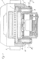
図1には、特に商用車のためのディスクブレーキが示されている。このディスクブレーキは基本構造としてブレーキキャリパ2を有していて、このブレーキキャリパはベンチレーテッドブレーキディスク1を有している。このブレーキディスク1は、商用車の図示されてない軸に固定されている。
FIG. 1 shows a disc brake, particularly for commercial vehicles. This disc brake has a
ブレーキキャリパ2は商用車のブレーキキャリア3に、ブレーキディスク1に関して軸方向に摺動可能に配置されている。
The
このために2つの固定エレメント4,5が設けられており、そのうちの固定エレメント5は可動軸受(フローティングベアリング)として形成されていて、固定エレメント4は不動軸受として形成されている。
For this purpose, two
両固定エレメント4,5はそれぞれ1つのスライドブシュ6,7と、このスライドブシュ6,7内に案内されたガイドバー8とを有している。この場合、外周面で円形のスライドブシュ6,7は、ブレーキキャリパ2の円形の孔内にプレス嵌めされている。
Both the
ガイドバー8はブレーキキャリア3にねじ込まれていて、従ってブレーキキャリパ2に対して定置であり、一方スライドブシュ6,7はブレーキキャリパ2に不動に結合されていて、従って軸受ピン8に沿ってブレーキキャリパ2と共に軸方向で摺動可能に支承されている。
The
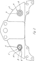
特に図2に示されているように、可動軸受5のスライドブシュ6は、横断面が円形ではなく、この実施例でほぼ楕円形の内孔9を有している。この孔の最大の幅は、不動軸受4が位置する平面で延びている。
As shown in FIG. 2 in particular, the
内孔9の最大の寸法に対して垂直に位置する最小の寸法は、円形のガイドバー8の直径にほぼ相当する。従って、内孔9に対してガイドバー8の側方の遊びが生じる。
The smallest dimension positioned perpendicular to the largest dimension of the
これに対して、不動軸受4のスライドブシュ7は円筒形の中空体として形成されていて、この場合、円筒状のガイドバー8は僅かな遊びをもって案内されているので、スライドブシュ7の、ひいてはブレーキキャリパ2の問題のない軸方向の摺動が可能である。
On the other hand, the
さらに図2により、特に明瞭には図3及び図4によっても明らかであるように、可動軸受5のスライドブシュ6は位置固定部材10を有している。この位置固定部材10は、スライドブシュ6が正確な位置で組み付けられている場合、ブレーキキャリパ2の孔の切欠11内に挿入されて、これによりスライドブシュ6は軸方向および回転方向で位置固定される。
Further, as clearly shown in FIG. 2 and particularly clearly in FIGS. 3 and 4, the
この場合、切欠11はポケット状に形成されていて、位置固定部材10は、図3及び図4に示した例では、2つの位置固定舌片12として形成されている。これらの位置固定舌片12は切欠11に押し込む前はフック状にスライドブシュ6の内孔9内に突入している。
In this case, the notch 11 is formed in a pocket shape, and the position fixing member 10 is formed as two position fixing tongues 12 in the example shown in FIGS. 3 and 4. These position fixing tongues 12 are inserted into the
最初に、切欠11内に位置固定舌片12を曲げ込むことにより、内孔9は、ガイドバー8が問題なく内孔9内に挿入できるほどに解放される。
First, by bending the position fixing tongue 12 into the notch 11, the
本発明によるスライドブシュ6の特に簡単な製造は、図5及び図6による実施例を可能にする。
A particularly simple manufacture of the
ここでは位置固定部材10は、一貫したほぼ円弧状の位置固定舌片から成っている。この位置固定舌片は、一点鎖線で示した位置に相応する完全には組み付けられていない状態では、内孔9によって規定された室内に突入しており、位置固定位置では、図5に実線で示したように凸状の折返し部として切欠11内に突入している。
Here, the position fixing member 10 is formed of a consistent substantially arc-shaped position fixing tongue. When the position fixing tongue is not completely assembled corresponding to the position indicated by the alternate long and short dash line, the position fixing tongue protrudes into the room defined by the
スライドブシュ6が金属から成っているので、位置固定部材10の切欠11内への押込みは、塑性変形によりスライドブシュ6の耐用期間全体にわたって継続的に維持するロック部を成している。
Since the
位置固定部材10の製造は特に、図5に示した実施例では極めて簡単である。図6に示したように、両縁部領域の一方に1つのスリット14がスライドブシュ6の壁に設けられている。このスリットにより、スリット14とスライドブシュ6の対応する端面との間に配置されている位置固定部材120の問題のない成形が可能である。
The manufacture of the position fixing member 10 is particularly simple in the embodiment shown in FIG. As shown in FIG. 6, one slit 14 is provided in the wall of the
必要に応じて勿論、位置固定部材10の別の形状も考えられる。多くのものと同様に、スライドブシュ6の必要に応じて、軸方向不動で回転不能である。
Of course, other shapes of the position fixing member 10 are also conceivable as required. Like many, the
いずれの場合も、切欠11(ポケット)、特にブレーキキャリパ2の孔の1つは位置固定部材10の最終形状にほぼ適合する。これによりほぼ遊びのない固定が、可能な両運動方向で保証されている。
In any case, the notch 11 (pocket), in particular one of the holes in the
1 ブレーキディスク、 2 ブレーキキャリパ、 3 ブレーキキャリア、 4,5 固定エレメント、 6,7 スライドブシュ、 8 ガイドバー、 9 内孔、 10 位置固定部材、 11 切欠、 12 位置固定舌片 DESCRIPTION OF SYMBOLS 1 Brake disc, 2 Brake caliper, 3 Brake carrier, 4,5 Fixing element, 6,7 Slide bush, 8 Guide bar, 9 Inner hole, 10 Position fixing member, 11 Notch, 12 Position fixing tongue
Claims (6)
可動軸受(5)のスライドブシュ(6)に少なくとも1つの位置固定部材(10)が設けられており、該位置固定部材(10)は、前記スライドブシュ(6)が正確な位置で組み付けられている場合に、該スライドブシュ(6)を軸方向及び周方向で位置固定するように、前記孔の切欠(11)内に挿入されており、前記位置固定部材(10)は、まず前記スライドブシュ(6)の内方に突入している少なくとも1つの位置固定舌片(12)から成っており、該位置固定舌片は前記スライドブシュ(6)の構成部分として、使用位置で塑性変形されながら前記孔の切欠(11)内に押し込まれていることを特徴とする、特に商用車のためのディスクブレーキ。In particular, a disc brake for a commercial vehicle is provided with a brake caliper (2) for gripping the brake disc (1), and the brake caliper (2) is fixed to two brake carriers (3) of the commercial vehicle. The element is fixed slidably in the axial direction with respect to the brake disc (1), one fixed element is formed as a stationary bearing (4) and the other fixed element is formed as a movable bearing (5), The movable bearing (5) has a slide bush (6) made of metal inserted into the hole of the brake caliper (2), and the inner and / or outer contour of the slide bush (6) is circular. In the slide bush (6), a guide bar (8) having a circular cross section, for example, is guided.
At least one of the stationary member (10) is provided on the slide bushing (6) of the movable bearing (5), said position fixing member (10), said slide bush (6) is assembled in the correct position If you are, to position fixing the slide bushing (6) in the axial direction and the circumferential direction, wherein is inserted into the notch (11) within the bore, said position fixing member (10), first the slide bush It comprises at least one position-fixing tongue (12) protruding inward of (6), and this position-fixing tongue as a constituent part of the slide bush (6) while being plastically deformed at the use position Disc brake, in particular for commercial vehicles, characterized in that it is pushed into the hole cutout (11).
可動軸受(5)のスライドブシュ(6)に少なくとも1つの位置固定部材(10)が設けられており、該位置固定部材(10)は、前記スライドブシュ(6)が正確な位置で組み付けられている場合に、該スライドブシュ(6)を軸方向及び周方向で位置固定するように、前記孔の切欠(11)内に挿入されており、前記位置固定部材(10)を形成するために、前記スライドブシュ(6)の両縁部領域の少なくとも一方に、まず前記スライドブシュ(6)の内方に突入している少なくとも1つの位置固定舌片(13)が設けられており、該位置固定舌片(13)は、前記スライドブシュ(6)の壁に設けられ軸方向に対して横方向に延びる少なくとも1つのスリット(14)によって画定されており、前記位置固定部材(10)としての前記位置固定舌片(13)は、外側の端面と前記スリット(14)との間に形成された領域の変形により形成されることを特徴とする、特に商用車のためのディスクブレーキ。 In particular, a disc brake for a commercial vehicle is provided with a brake caliper (2) for gripping the brake disc (1), and the brake caliper (2) is fixed to two brake carriers (3) of the commercial vehicle. The element is fixed slidably in the axial direction with respect to the brake disc (1), one fixed element is formed as a stationary bearing (4) and the other fixed element is formed as a movable bearing (5), The movable bearing (5) has a slide bush (6) made of metal inserted into the hole of the brake caliper (2), and the inner and / or outer contour of the slide bush (6) is circular. In the slide bush (6), a guide bar (8) having a circular cross section, for example, is guided.
At least one position fixing member (10) is provided on the slide bush (6) of the movable bearing (5), and the position fixing member (10) is assembled with the slide bush (6) at an accurate position. In order to form the position fixing member (10), the slide bush (6) is inserted into the notch (11) of the hole so as to fix the position of the slide bush (6) in the axial direction and the circumferential direction . At least one position-fixing tongue piece (13) projecting inwardly of the slide bush (6) is provided in at least one of both edge regions of the slide bush (6). tongue (13), the slide bush being defined by at least one slit extending in a direction transverse to the axial direction provided in a wall (6) (14), prior to the said position fixing member (10) Serial position fixing tongue (13) is characterized by being formed by deformation of the formed area between the outer end face and said slit (14), disk brake, particularly for commercial vehicles.
Applications Claiming Priority (3)
| Application Number | Priority Date | Filing Date | Title |
|---|---|---|---|
| DE10311896A DE10311896A1 (en) | 2003-03-18 | 2003-03-18 | Disc brake, in particular for commercial vehicles |
| DE10311896.9 | 2003-03-18 | ||
| PCT/EP2004/002804 WO2004083665A1 (en) | 2003-03-18 | 2004-03-18 | Disk brake, especially for commercial vehicles |
Publications (2)
| Publication Number | Publication Date |
|---|---|
| JP2006520451A JP2006520451A (en) | 2006-09-07 |
| JP4829101B2 true JP4829101B2 (en) | 2011-12-07 |
Family
ID=32920894
Family Applications (1)
| Application Number | Title | Priority Date | Filing Date |
|---|---|---|---|
| JP2006504720A Expired - Fee Related JP4829101B2 (en) | 2003-03-18 | 2004-03-18 | Disc brakes especially for commercial vehicles |
Country Status (10)
| Country | Link |
|---|---|
| US (1) | US7543689B2 (en) |
| EP (1) | EP1606530B1 (en) |
| JP (1) | JP4829101B2 (en) |
| CN (1) | CN100381725C (en) |
| AT (1) | ATE388345T1 (en) |
| BR (1) | BRPI0408421A (en) |
| CA (1) | CA2519430C (en) |
| DE (2) | DE10311896A1 (en) |
| MX (1) | MXPA05009827A (en) |
| WO (1) | WO2004083665A1 (en) |
Families Citing this family (15)
| Publication number | Priority date | Publication date | Assignee | Title |
|---|---|---|---|---|
| DE102004055527A1 (en) * | 2004-11-17 | 2006-05-24 | Knorr-Bremse Systeme für Nutzfahrzeuge GmbH | Disc brake, in particular for a commercial vehicle |
| DE102008034653A1 (en) * | 2008-07-25 | 2010-01-28 | Knorr-Bremse Systeme für Nutzfahrzeuge GmbH | Disc brake, in particular for a commercial vehicle |
| DE102009007330A1 (en) | 2009-02-04 | 2010-08-05 | Bpw Bergische Achsen Kg | Vehicle disc brake |
| EP2626585B1 (en) * | 2012-02-08 | 2014-12-10 | Meritor Heavy Vehicle Braking Systems (UK) Limited | Guide pin |
| DE102014115765A1 (en) * | 2014-10-30 | 2016-05-04 | Knorr-Bremse Systeme für Nutzfahrzeuge GmbH | Disc brake for a commercial vehicle |
| EP3415781B1 (en) * | 2015-06-04 | 2020-04-22 | Meritor Heavy Vehicle Braking Systems (UK) Limited | Guide assembly |
| USD771540S1 (en) * | 2015-06-15 | 2016-11-15 | Saf-Holland, Inc. | Brake spider |
| DE102015114737A1 (en) * | 2015-09-03 | 2017-03-09 | Bpw Bergische Achsen Kg | Brake caliper guide for a disc brake, guide rail for a caliper guide and bellows for mounting on a caliper guide |
| DE102015217522A1 (en) * | 2015-09-14 | 2017-03-16 | Robert Bosch Gmbh | Electromechanical brake booster and brake system |
| DE102016109001A1 (en) * | 2016-05-17 | 2017-11-23 | Knorr-Bremse Systeme für Nutzfahrzeuge GmbH | Disc brake for a commercial vehicle |
| US10429020B2 (en) * | 2016-11-14 | 2019-10-01 | Promier Products, Inc. | Wireless portable light source system with multiple mounting and control modes |
| GB2551855B (en) * | 2016-11-16 | 2019-08-14 | Mei Brakes Ltd | Sliding caliper disc brake |
| DE102019104125A1 (en) * | 2019-02-19 | 2020-08-20 | Knorr-Bremse Systeme für Nutzfahrzeuge GmbH | Ball screw drive with anti-twist device |
| EP3859181A1 (en) * | 2020-02-03 | 2021-08-04 | Meritor Heavy Vehicle Braking Systems (UK) Limited | Guide assembly |
| EP4001687A1 (en) | 2020-11-16 | 2022-05-25 | ZF CV Systems Europe BV | Disc brake for vehicles, in particular for commercial vehicles |
Citations (3)
| Publication number | Priority date | Publication date | Assignee | Title |
|---|---|---|---|---|
| JPS5519859A (en) * | 1978-07-28 | 1980-02-12 | Nec Corp | Ring laser |
| JPS55132424A (en) * | 1979-03-26 | 1980-10-15 | Bendix Corp | Disc brake |
| JPH07286609A (en) * | 1994-04-15 | 1995-10-31 | Fujitsu Ltd | Mounting structure |
Family Cites Families (12)
| Publication number | Priority date | Publication date | Assignee | Title |
|---|---|---|---|---|
| US3841446A (en) * | 1973-06-26 | 1974-10-15 | Bendix Corp | Disc brake caliper and anti-rattle support |
| JPS5825893B2 (en) * | 1975-08-14 | 1983-05-30 | トキコ株式会社 | disc brake |
| JPS5519859U (en) * | 1978-07-25 | 1980-02-07 | ||
| US4385680A (en) * | 1978-08-28 | 1983-05-31 | The Bendix Corporation | Pin slider disc brake |
| JPS5554732A (en) * | 1978-10-18 | 1980-04-22 | Hosei Brake Kogyo Kk | Pin slide disc brake |
| US5012902A (en) * | 1989-09-29 | 1991-05-07 | Allied-Signal Inc. | Caliper and retaining pin spacer |
| FR2716509B1 (en) * | 1994-01-19 | 1996-04-12 | Alliedsignal Automotive Espana | Disc brake with increased safety. |
| FR2725765A1 (en) * | 1994-10-13 | 1996-04-19 | Alliedsignal Europ Services | IMPROVED MOUNT DISC BRAKE |
| JPH09250572A (en) * | 1996-03-15 | 1997-09-22 | Akebono Brake Ind Co Ltd | Disc brake |
| JP2001254767A (en) * | 2000-03-08 | 2001-09-21 | Tokico Ltd | Disc brake |
| WO2003025413A1 (en) * | 2001-09-18 | 2003-03-27 | Knorr-Bremse Systeme für Nutzfahrzeuge GmbH | Disc brake, in particular for a utility vehicle |
| JP2005009611A (en) * | 2003-06-20 | 2005-01-13 | Advics:Kk | Floating type disk brake |
-
2003
- 2003-03-18 DE DE10311896A patent/DE10311896A1/en not_active Withdrawn
-
2004
- 2004-03-18 MX MXPA05009827A patent/MXPA05009827A/en active IP Right Grant
- 2004-03-18 CN CNB2004800071514A patent/CN100381725C/en not_active Expired - Lifetime
- 2004-03-18 DE DE502004006414T patent/DE502004006414D1/en not_active Expired - Lifetime
- 2004-03-18 BR BRPI0408421-7A patent/BRPI0408421A/en not_active Application Discontinuation
- 2004-03-18 EP EP04721510A patent/EP1606530B1/en not_active Expired - Lifetime
- 2004-03-18 JP JP2006504720A patent/JP4829101B2/en not_active Expired - Fee Related
- 2004-03-18 CA CA2519430A patent/CA2519430C/en not_active Expired - Lifetime
- 2004-03-18 AT AT04721510T patent/ATE388345T1/en not_active IP Right Cessation
- 2004-03-18 WO PCT/EP2004/002804 patent/WO2004083665A1/en active IP Right Grant
- 2004-03-18 US US10/549,690 patent/US7543689B2/en active Active
Patent Citations (3)
| Publication number | Priority date | Publication date | Assignee | Title |
|---|---|---|---|---|
| JPS5519859A (en) * | 1978-07-28 | 1980-02-12 | Nec Corp | Ring laser |
| JPS55132424A (en) * | 1979-03-26 | 1980-10-15 | Bendix Corp | Disc brake |
| JPH07286609A (en) * | 1994-04-15 | 1995-10-31 | Fujitsu Ltd | Mounting structure |
Also Published As
| Publication number | Publication date |
|---|---|
| DE502004006414D1 (en) | 2008-04-17 |
| DE10311896A1 (en) | 2004-09-30 |
| ATE388345T1 (en) | 2008-03-15 |
| US20070029147A1 (en) | 2007-02-08 |
| EP1606530A1 (en) | 2005-12-21 |
| CA2519430A1 (en) | 2004-09-30 |
| US7543689B2 (en) | 2009-06-09 |
| CN100381725C (en) | 2008-04-16 |
| CA2519430C (en) | 2012-01-10 |
| WO2004083665A1 (en) | 2004-09-30 |
| CN1761822A (en) | 2006-04-19 |
| BRPI0408421A (en) | 2006-03-21 |
| MXPA05009827A (en) | 2005-12-06 |
| JP2006520451A (en) | 2006-09-07 |
| EP1606530B1 (en) | 2008-03-05 |
Similar Documents
| Publication | Publication Date | Title |
|---|---|---|
| JP4829101B2 (en) | Disc brakes especially for commercial vehicles | |
| JP6893240B2 (en) | Tilting pad bearing | |
| KR101004703B1 (en) | Circular-Shank Tool Comprising a Tool holder | |
| EP3415781B1 (en) | Guide assembly | |
| US9845837B2 (en) | Guide assembly for a disc brake | |
| CN101351651B (en) | Mounting structure | |
| JP4086827B2 (en) | Floating caliper type disc brake | |
| US5308207A (en) | Retaining ring and shaft for securing a component thereon | |
| JPWO2004043651A1 (en) | Retaining ring mounting tool | |
| JP6982493B2 (en) | Pad clips, pad clip and return spring assemblies, and floating disc brakes | |
| KR20150086482A (en) | Guide pin for disc brake assembly, disc brake assembly including such a guide pin and method for producing a disc brake assembly including such a guide pin | |
| US8348515B2 (en) | Axial bearing with an axial angle disk with a securing tab producing a secured mounting and carrier with such an axial bearing | |
| JP4630258B2 (en) | Shift knob mounting structure | |
| CN112392876B (en) | Guide assembly for a disc brake | |
| BR0212557B1 (en) | disc brake, especially for a utility vehicle. | |
| US20060090978A1 (en) | Overrunning clutch | |
| CN104709339B (en) | Retainer cap for shaft assembly | |
| JP4475671B2 (en) | Rocker arm | |
| KR100792824B1 (en) | Mounting bush of gear box for steering system | |
| US20220397171A1 (en) | Brake caliper having a faceplate | |
| WO2024004233A1 (en) | Linear motion device | |
| JP2011099480A (en) | Cage for roller bearing and roller bearing | |
| JP3126970U (en) | Chain connection pin | |
| KR100380240B1 (en) | Universal joint of steering axis for car | |
| JP2001140852A (en) | Ball joint |
Legal Events
| Date | Code | Title | Description |
|---|---|---|---|
| A621 | Written request for application examination |
Free format text: JAPANESE INTERMEDIATE CODE: A621 Effective date: 20070309 |
|
| A977 | Report on retrieval |
Free format text: JAPANESE INTERMEDIATE CODE: A971007 Effective date: 20100617 |
|
| A131 | Notification of reasons for refusal |
Free format text: JAPANESE INTERMEDIATE CODE: A131 Effective date: 20100624 |
|
| A601 | Written request for extension of time |
Free format text: JAPANESE INTERMEDIATE CODE: A601 Effective date: 20100924 |
|
| A602 | Written permission of extension of time |
Free format text: JAPANESE INTERMEDIATE CODE: A602 Effective date: 20101001 |
|
| A521 | Request for written amendment filed |
Free format text: JAPANESE INTERMEDIATE CODE: A523 Effective date: 20101222 |
|
| RD04 | Notification of resignation of power of attorney |
Free format text: JAPANESE INTERMEDIATE CODE: A7424 Effective date: 20101228 |
|
| TRDD | Decision of grant or rejection written | ||
| A01 | Written decision to grant a patent or to grant a registration (utility model) |
Free format text: JAPANESE INTERMEDIATE CODE: A01 Effective date: 20110902 |
|
| A01 | Written decision to grant a patent or to grant a registration (utility model) |
Free format text: JAPANESE INTERMEDIATE CODE: A01 |
|
| A61 | First payment of annual fees (during grant procedure) |
Free format text: JAPANESE INTERMEDIATE CODE: A61 Effective date: 20110915 |
|
| FPAY | Renewal fee payment (event date is renewal date of database) |
Free format text: PAYMENT UNTIL: 20140922 Year of fee payment: 3 |
|
| R150 | Certificate of patent or registration of utility model |
Free format text: JAPANESE INTERMEDIATE CODE: R150 |
|
| R250 | Receipt of annual fees |
Free format text: JAPANESE INTERMEDIATE CODE: R250 |
|
| LAPS | Cancellation because of no payment of annual fees |