JP4826585B2 - Confocal microscope - Google Patents
Confocal microscope Download PDFInfo
- Publication number
- JP4826585B2 JP4826585B2 JP2007525916A JP2007525916A JP4826585B2 JP 4826585 B2 JP4826585 B2 JP 4826585B2 JP 2007525916 A JP2007525916 A JP 2007525916A JP 2007525916 A JP2007525916 A JP 2007525916A JP 4826585 B2 JP4826585 B2 JP 4826585B2
- Authority
- JP
- Japan
- Prior art keywords
- light
- confocal microscope
- microscope apparatus
- data
- image data
- Prior art date
- Legal status (The legal status is an assumption and is not a legal conclusion. Google has not performed a legal analysis and makes no representation as to the accuracy of the status listed.)
- Expired - Fee Related
Links
Images


Classifications
-
- G—PHYSICS
- G02—OPTICS
- G02B—OPTICAL ELEMENTS, SYSTEMS OR APPARATUS
- G02B21/00—Microscopes
- G02B21/0004—Microscopes specially adapted for specific applications
- G02B21/002—Scanning microscopes
- G02B21/0024—Confocal scanning microscopes (CSOMs) or confocal "macroscopes"; Accessories which are not restricted to use with CSOMs, e.g. sample holders
- G02B21/008—Details of detection or image processing, including general computer control
Description
【技術分野】
【0001】
本発明は、生体試料などを観察するための共焦点顕微鏡装置に関する。
【背景技術】
【0002】
共焦点顕微鏡は、共焦点絞りを用いて実効的な焦点深度を浅くし、観察対象を試料中の薄い層に限定(セクショニング)する顕微鏡である(特許文献1,特許文献2など)。
特許文献1には、観察対象となる層の厚さ(セクショニング分解能)を可変にするために、共焦点絞りの径を変更する技術(1)や、ピンホール径の異なる複数種類のピンホール部材を共焦点絞り面に切り替え配置する技術(2)などが開示されている。
【0003】
また、特許文献2には、セクショニングの機能をオン/オフするために、共焦点絞りの内外に入射する光を分岐して個別に検出し、それらの検出信号を必要に応じて加算する技術(3)が開示されている。
【特許文献1】
実開平6−16927号公報
【特許文献2】
特開平10−104522号公報
【発明の開示】
【発明が解決しようとする課題】
【0004】
仮に、(1),(2),(3)の技術を応用してセクショニング分解能を様々に変更しようとしたならば、共焦点絞りの径の可変ステップ数、ピンホール部材の種類数、光の分岐数をそれぞれ増やせばよいと考えられる。しかし、何れにせよ、検出に関わる部分の機構や光学系が複雑になり、コストや位置合わせ精度の面で困難の生じる可能性がある。
そこで本発明は、共焦点顕微鏡の構成をシンプルに抑えながらセクショニング分解能の変更の自由度を高めることのできる共焦点顕微鏡装置を提供することを目的とする。
【課題を解決するための手段】
【0005】
本発明の共焦点顕微鏡装置は、光源と、前記光源からの光を試料に集光する照明光学系と、前記試料からの光を結像する結像光学系と、前記結像光学系に関し前記試料の集光点と略共役な位置に入射する光を、少なくとも前記試料の前記集光点の近傍領域からの光と、その周辺領域からの光とに分離し、それぞれ検出する検出手段とを備え、前記検出手段は、前記結像光学系の焦点深度内に光軸に対して傾斜して配置された光学部材と、前記光学部材において前記集光点と略共役な位置に設けられ、かつその位置に入射する光を前記近傍領域からの光と前記周辺領域からの光とに分離する光分離面と、前記近傍領域からの光と前記周辺領域からの光とを独立して検出する検出器とを有し、前記近傍領域からの光を検出した前記検出器が生成する第1のデータと、前記周辺領域からの光を検出した前記検出器が生成する第2のデータとを用いて、任意のセクショニング分解能のデータを演算する演算手段を更に備えたことを特徴とする。
【0006】
また、前記演算には、前記第1のデータと、前記第2のデータとの重み付け和の演算が含まれることが望ましい。
また、前記第1のデータの重み係数を1とすると、前記第2のデータの重み係数αは、1≧αの範囲に設定されるとよい。
【0007】
また、前記演算には、前記第1のデータを、前記第2のデータで除する演算が含まれてもよい。
また、前記光分離面は、前記近傍領域からの光を受ける円形の第1面と、前記周辺領域からの光を受ける第2面とを有し、前記光学部材は、前記周辺領域からの光の光路に対し直列の関係で複数の前記光分離面を配置しており、前記複数の光分離面の間では、後段に配置されたものほど前記第1面の径が大きく設定されるとよい。
また、前記検出手段は、複数の前記検出器を備えてもよい。
また、前記検出手段は、前記第1のデータを検出する第1の検出器と、前記第2のデータを検出する第2の検出器とを有してもよい。
【0008】
本発明によれば、共焦点顕微鏡の構成をシンプルに抑えながらセクショニング分解能の変更の自由度を高めることのできる共焦点顕微鏡装置が実現する。
【図面の簡単な説明】
【0009】
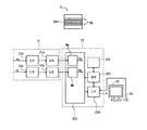
【図1】第1実施形態の共焦点顕微鏡システムの構成図である。
【図2】第1実施形態の検出部10を説明する図である。
【図3】回路部21及びコンピュータ22による検出信号sa,sbの処理を説明する図である。
【図4】指定分解能、重み係数α、画像データDの関係を示す図である。
【図5】(A),(B)は、rb=3raの設定下で取得された各画像データに反映されている情報を示す図である。(C)は、rb=3raの設定下で取得された積(Da・Db)に反映されている情報を示す図であり、(D)は、rb=3raの設定下で取得された商(Da/Db)に反映されている情報を示す図である。
【図6】(A),(B)は、rb=4raの設定下で取得された各画像データに反映されている情報を示す図である。(C)は、rb=4raの設定下で取得された積(Da・Db)に反映されている情報を示す図であり、(D)は、rb=4raの設定下で取得された商(Da/Db)に反映されている情報を示す図である。
【図7】検出部10の変形例を示す図である。
【図8】検出部10の別の変形例を示す図である。
【図9】検出部10のさらに別の変形例を示す図である。
【図10】第2実施形態の検出部10を説明する図である。
【図11】第2実施形態においてα=+0.8,β=−1.6の設定下で取得された画像データDに反映されている情報を示す図である。
【発明を実施するための最良の形態】
【0010】
[第1実施形態]
本発明の第1実施形態を説明する。本実施形態は、共焦点顕微鏡システムの実施形態である。
図1は、本システムの構成図である。図1に示すように、本システムには、共焦点顕微鏡の構成要素として、光源11、照明用レンズ12、フィルタ13、ダイクロイックミラー14、ガルバノミラー15、対物レンズ16、フィルタ17、集光レンズ18、検出部10などが備えられる。また、本システムには、共焦点顕微鏡を駆動制御するために、回路部21、コンピュータ22なども備えられる。なお、コンピュータ22には、モニタ23、及び入力器24が接続されると共に、本システムを動作させるために必要なプログラムが、インターネットや記録媒体を介して予めインストールされている。
【0011】
本システムにおいて、光源11から射出した照明光は、照明用レンズ12、フィルタ13、ダイクロイックミラー14、ガルバノミラー15、対物レンズ16を介して試料0上に集光する。その集光点にて発生した観察光束は、対物レンズ16、ガルバノミラー15、ダイクロイックミラー14、フィルタ17、集光レンズ18を介して検出部10へ入射する。検出部10は、入射した観察光束に基づき、試料0上の集光点の情報を取得する。
【0012】
ガルバノミラー15が駆動されると、試料0上を集光点が二次元走査するので、検出部10は、その期間に発生した観察光束に基づき、試料0の二次元情報(顕微鏡画像の情報)を取得することができる。
図2は、本実施形態の検出部10を説明する図である。図2に示すように、検出部10には、マスク部材101と、2つの光検出器102a,102bとが備えられる。
【0013】
マスク部材101は、観察光束に対し透明な基板上に、適当なパターンの反射膜等を形成したものである。このマスク部材101が配置されるのは、集光レンズ18の焦点近傍である。このマスク部材101上に、ピンホールマスク10A、反射面10R、及びピンホールマスク10Bが形成されている。
ピンホールマスク10Aは、共焦点絞り面、すなわち、集光レンズ18の焦点深度内の略中央の面に、傾斜した姿勢で配置される。ピンホールマスク10Aの入射側のマスク面は、反射面になっている。よって、ピンホールマスク10Aに入射した観察光束のうち、ピンホール10a内に集光する観察光束は、ピンホールマスク10Aを透過し、ピンホール10aの周辺に入射した観察光束は、ピンホールマスク10Aで反射する。
【0014】
反射面10Rは、ピンホールマスク10Aで反射した観察光束を受ける位置に、ピンホールマスク10Aの反射面と平行に配置されており、その観察光束を反射する働きをする。
ピンホールマスク10Bは、反射面10Rで反射された観察光束を受ける位置に、ピンホールマスク10Aと中心が一致するように配置される。集光レンズ10の焦点深度は十分に深く、ピンホールマスク10Aからピンホールマスク10Bまでの光路に比して十分長いため、このピンホールマスク10Bの配置箇所も、集光レンズ10の焦点深度内に収まっている。ピンホールマスク10Bのピンホール10bの径rbは、ピンホールマスク10Aのピンホール10aの径raよりも大きく、径raの2倍(rb=2ra)に設定される。ピンホールマスク10Bに入射した観察光束のうち、ピンホール10b内に入射する観察光束は、そのピンホールマスク10Bを透過し、ピンホール10bの周辺に入射した観察光束は、そのピンホールマスク10Bでカットされる。
【0015】
なお、図2の左部には、観察光束の断面、ピンホール10a、ピンホール10bの大凡の大小関係を示した。
以上のマスク部材101によれば、集光レンズ18からの観察光束が、「ピンホール10aに入射した観察光束」と、「ピンホール10aには入射せずにピンホール10bに入射した観察光束」との2種類に分離される。つまり、「共焦点絞り面の中央の円形領域に入射した観察光束」と、「前記円形領域の周りのドーナツ状領域に入射した観察光束」との2種類に分離される。そして、前者の光量は、光検出器102aによって検出され、後者の光量は、光検出器102bによって検出される。つまり、2種類の観察光束は、同時かつ個別に検出される。
【0016】
これらの光検出器102a,102bは、上述した二次元走査中に連続的に駆動され、検出信号sa,sbを繰り返し生成する。それらの検出信号sa,sbは、本システムの回路部21へ逐次取り込まれる。
図3は、回路部21及びコンピュータ22による検出信号sa,sbの処理を説明する図である。図3に示すとおり、回路部21には、検出信号sa,sbを並列処理するために、2つのI/V変換器21a,21bと、2つのA/D変換器21a’,21b’とが備えられる。また、コンピュータ22には、CPU221、記憶部(RAM,ハードディスク等)222、画像ボード223、I/F回路224などが備えられる。このうち、画像ボード223には、少なくとも2つのフレームメモリMa,Mbが備えられる。
【0017】
さて、一方の検出信号saは、I/V変換器21a、A/D変換器21a’を順に介してフレームメモリMaへ逐次取り込まれる。CPU221は、フレームメモリMa上の1フレーム分の検出信号saに基づき、試料0の顕微鏡画像を示す画像データDaを作成し、記憶部222に格納する。この画像データDaの基となったのは、共焦点顕微鏡の小さい方のピンホールに集光した観察光束である。よって、画像データDaは、図3の上部に示すとおり、試料0中のピント位置近傍の層(特定層)の情報を多く含む。
【0018】
また、他方の検出信号sbは、I/V変換器21b、A/D変換器21b’を順に介してフレームメモリMbへ逐次取り込まれる。CPU221は、フレームメモリMb上の1フレーム分の検出信号sbに基づき、試料0の顕微鏡画像を示す画像データDbを作成し、記憶部222に格納する。この画像データDbの基となったのは、共焦点顕微鏡の小さい方のピンホールに集光せずに大きい方のピンホールに入射した観察光束である。よって、画像データDbは、図3の上部に示すとおり、試料0中の特定層の周辺の層(周辺層)の情報を多く含む。
【0019】
ここで、本システムのオペレータは、画像データDa,Dbの取得前や取得後の所望のタイミングで、コンピュータ22に対しセクショニング分解能を指定することができる。その分解能の指定は、入力器24を介して行われる。
オペレータが指定できるのは、例えば、「高」から「低」までの範囲内の任意の分解能である。その指定内容(指定分解能)は、I/F回路224を経由してCPU221によって認識される。CPU221は、指定分解能に応じた演算を画像データDa,Dbに施して画像データDを作成し、それをモニタ23へ表示させる。
【0020】
その作成のための演算は、画像データDa,Dbのピクセル毎の重み付け和であり、例えば、次式(1)で表される。
D=Da+α・Db ・・・(1)
そして、式(1)中の重み係数αは、指定分解能に応じた値に設定される。重み係数αの採り得る範囲は、例えば、+1≧α≧−1である。指定分解能が高いほど重み係数αは−1に近い値に設定され、指定分解能が低いほど重み係数αは+1に近い値に設定される。
【0021】
但し、重み係数αが負に設定されたときには、作成された画像データDの一部のピクセル値が負になる可能性がある。その場合、負となったピクセル値は「0」に置き換えられるとよい。また、作成された画像データDは、表示画像のダイナミックレンジを超過する可能性があるので、ダイナミックレンジに適合するよう、その表示前に変換される必要がある。
【0022】
例えば、CPU221は、画像データDのうち、ダイナミックレンジを超過するピクセルについては、そのピクセル値を無視してダイナミックレンジの最大値(16ビットなら65535)に置換する。
或いは、CPU221は、画像データDの全体を、ダイナミックレンジに適合するように、規格化する。因みに、その場合は、画像データDを作成するときに、上式(1)に代えて下式(2)を用いればよい。下式(2)は、重み付け平均の式である。
【0023】
D=(Da+α・Db)/(1+α) ・・・(2)
図4は、指定分解能、重み係数α、画像データDの関係を示す図である。図4では、「高」,「中」,「低」を含む7種類の指定分解能に関するデータを代表して示した。また、図4では、そのデータと共に、本システムに設定された仮想的な共焦点絞りの径の概念を示した。
【0024】
先ず、指定分解能が「中」であるときには、重み係数αは「0」に設定される。その場合、画像データDは、特定層の情報を多く含む画像データDaと同じになる。したがって、画像データDのセクショニング分解能は、特定層の厚さ程度になる。これは、本システムの仮想的な共焦点絞りの径を、「ra」(=小さい方のピンホールの径)に設定したことに相当する。
【0025】
また、指定分解能が「高」であるときには、重み係数αは「−1」に設定される。その場合、画像データDは、特定層の情報を多く含む画像データDaから、周辺層の情報を多く含む画像データDbを減算したものとなる。その減算により、周辺層の情報(顕微鏡画像上でボケとなって現れる成分)を、データのS/Nを保ったまま差し引くことができ、画像データDのセクショニング分解能は、特定層よりも薄くなる。
【0026】
また、指定分解能が「低」であるときには、重み係数αは「+1」に設定される。その場合、画像データDは、特定層の情報を多く含む画像データDaと、周辺層の情報を多く含む画像データDbとを加算したものとなる。したがって、画像データDのセクショニング分解能は、特定層と周辺層との合計の厚さになる。これは、本システムの仮想的な共焦点絞りの径を、「rb」(=大きい方のピンホールの径)に設定したことに相当する。
【0027】
また、指定分解能が「高」と「中」との間であるときには、重み係数αは「−1」と「0」との間の値(−0.75,−0.5など)に設定される。このとき、画像データDのセクショニング分解能は、指定分解能が「高」のときと指定分解能が「中」のときとの間の分解能になる。
また、指定分解能が「中」と「低」との間であるときには、重み係数αは「0」と「1」との間の値(+0.5,+0.75など)に設定される。このとき、画像データDのセクショニング分解能は、指定分解能が「中」のときと、指定分解能が「低」のときとの間の分解能になる。これは、本システムの仮想的な共焦点絞りの径を、raとrbとの間に設定した場合と類似の分解能に相当する。
【0028】
すなわち、本システムは、オペレータからの指示に従い、仮想的な共焦点絞りの径を、ra’〜rbの範囲内で自在に変化させることと類似の操作ができる。
(第1実施形態の効果)
以上説明したとおり、本システムでは、共焦点顕微鏡が実測した画像データは、セクショニングの異なる画像データDa,Dbの2種類のみである。したがって、検出部10に必要なピンホールマスクの数は「2」であり、その構成はシンプルである(図2参照)。
【0029】
このように、セクショニングの異なる2つの観察光束、すなわち「共焦点絞り面の中央の円形領域に入射した観察光束」と、「この円形領域の周りのドーナツ状領域(或いはその円形領域を包含する広い円形領域)に入射した観察光束」とをもとにすれば、演算によりセクショニング分解能の異なる画像データを求めることができる。
したがって、本システムでは、セクショニング分解能を変化させる際、共焦点顕微鏡は何ら動作することなく、コンピュータ22の演算上で仮想的な共焦点絞りの径を変化させるだけである。したがって、オペレータは、セクショニング分解能を任意のタイミングで任意に変化させることができる。また、セクショニング分解能の変更の際、試料0に対し照明光を改めて照射する必要がないので、試料0にダメージを与えることはない。
【0030】
しかも、2種類の画像データDa,Dbは、並行して取得されるので、試料0に対する照明光の照射量は必要最小限に抑えられ、試料0のダメージも必要最小限に抑えることができる。
また、本システムの仮想的な共焦点絞りの径の可変範囲はra’〜rbであり、その下限値ra’は、共焦点顕微鏡に実際に備えられた小さい方のピンホールの径raよりも小さい(図4参照)。これは、演算式(式(1)又は式(2))中の重み係数αの採り得る範囲に、負の範囲(α<0)を含めたからである。したがって、共焦点顕微鏡の単体が保有している能力よりも高いセクショニング分解能が実現する。
【0031】
また、演算式(式(1)又は式(2))は、単純な重み付け和の式又は重み付け平均の式なので、コンピュータ22は、仮想的な共焦点絞りの径を極めて短時間のうちに変化させることができる。したがって、本システムでは、モニタ23上に顕微鏡画像を表示させながら、そのセクショニング分解能をリアルタイムで変化させることも可能である。
(ピンホール径の変形例)
本実施形態では、大きい方のピンホールの径rbを、小さい方のピンホールの径raの2倍に設定したが、他の倍率に設定してもよい。但し、径rbは径raの4倍よりも小さいことが望ましい。以下、3倍であるときと4倍であるときとの相違を説明する。
【0032】
図5(A),(B)は、rb=3raの設定下で取得された各画像データに反映されている情報を示す図(試料の深さ位置−反映光量の相対値)である。カーブの幅が狭いほどセクショニング分解能が高く、カーブの高さが高いほど明るいことを示している。図5(A)のD(α:+1),D(α:+0.5)は、α=+1,α=+0.5のときの画像データDのカーブであり、図5(B)のD(α:−1),D(α:−0.5)は、α=−1,α=−0.5のときの画像データDのカーブである。
【0033】
図5(A),(B)を参照すると、画像データDaには試料0の特定層の情報が多く含まれており、画像データDbにはその周辺層の情報が多く含まれていることがわかる。そして、画像データD(α:+1),D(α:+0.5),D(α:−1),D(α:−0.5)のカーブは、何れも或る程度の幅と高さを持っていることがわかる。また、これらのカーブD(α:+1),D(α:+0.5),D(α:−1),D(α:−0.5)の幅を比較すると、明確な差異が生じていることもわかる。
【0034】
したがって、rb=3raの設定は、セクショニング分解能を各種に変更するのに適していることがわかる。
一方、図6(A),(B)は、rb=4raの設定下で取得された各画像データに反映されている情報を示す図である。図6(A),(B)の表示方法は、図5(A),(B)におけるそれと同じである。
【0035】
図6(A),(B)を参照すると、画像データD(α:+0.5)のカーブは、中央部が他の部分と比較して尖り過ぎていることがわかる。また、画像データD(α:−1),D(α:−0.5)のカーブは、急峻過ぎると共に、両者の幅を比較しても明確な差異が生じていないことがわかる。
したがって、rb=4raの設定は、セクショニング分解能を各種に変更するのにあまり適さないことがわかる。
【0036】
すなわち、セクショニング分解能を様々に変更するためには、rb<4raと設定する必要がある。特に、本実施形態のようにrb=2raと設定すれば、指定分解能と重み係数αとの関係がシンプルになる(すなわち、指定分解能に応じて重み係数αを−1〜+1の範囲でシフトすればよい)という利点もある。
(演算内容の変形例)
本実施形態(rb=2raの場合)では、重み係数αの採り得る範囲の上限を「+1」としたが、+1よりも大きくして範囲を拡大してもよい。
【0037】
因みに、仮想的な共焦点絞りに設定される径のサイズと、重み係数αとの間の関係は、径ra,rbの間の関係によって異なるので、指定分解能と重み係数αとの関係は、径ra,rbの間の関係に応じて適切に設定される必要がある。
また、本実施形態では、画像データDを作成するに当たり、画像データDa,Dbの重み付き和を求めたが(式(1),(2)参照)、画像データDa,Dbの積(Da・Db)や、画像データDa,Dbの商(Da/Db)を求め、それらを画像データDの作成に使用してもよい。
【0038】
図5(C)は、rb=3raの設定下で取得された積(Da・Db)に反映されている情報を示す図であり、図5(D)は、rb=3raの設定下で取得された商(Da/Db)に反映されている情報を示す図である。
このうち、特に、商(Da/Db)のカーブ(図5(D))は、図5(B)に示した画像データD(α:−1)のカーブと似ている。よって、本実施形態では、画像データD(α:−1)の代わりに、商(Da/Db)を使用することも可能である。
【0039】
但し、商(Da/Db)をそのまま画像データDとして使用すると、画像データDの一部のピクセル値が異常値になる可能性がある。それを防ぐため、画像データDbにおいて特に値の小さかったピクセル(例えば、最大値の10分の1未満)に限り、商(Da/Db)の代わりに、画像データDaのピクセル値をそのまま用いることにすればよい。
因みに、図6(C)は、rb=4raの設定下で取得された積(Da・Db)に反映されている情報を示す図であり、図6(D)は、rb=4raの設定下で取得された商(Da/Db)に反映されている情報を示す図である。このうち、図6(D)を参照すると、rb=4raの設定下であっても、商(Da/Db)のカーブは、形状が良好であることがわかる。よって、rb=4raの設定下であっても、商(Da/Db)については、セクショニング分解能の高い画像データDとして利用できる可能性がある。
【0040】
また、本実施形態においては、コンピュータ22内で行われた演算の一部又は全部を、回路部21に行わせてもよい(その場合、回路部21内に加算器や乗算器が備えられる。)。但し、何れも場合も、実測した画像データDa,Dbを演算処理前に個別に記憶しておき、それを必要なときにのみ演算処理する方が、演算内容を自由に変更できるという利点がある。
【0041】
(検出部10の変形例)
検出部10は、図7に示すとおり変形されてもよい。図7は、本変形例の検出部10を説明する図である。この検出部10にも、径の小さいピンホールマスク10Aと、径の大きいピンホールマスク10Bと、2つの光検出器102a,102bが備えられる。
ピンホールマスク10Aは、第1実施形態のそれと同様に、集光レンズ18の焦点深度内の略中央の面に傾斜した姿勢で配置される。また、ピンホールマスク10Aの入射側のマスク面は、第1実施形態のそれと同様に、反射面になっている。
【0042】
一方、ピンホールマスク10Bは、ピンホールマスク10Aの反射光路上、かつピンホールマスク10Aから離れた位置に配置されている。但し、ピンホールマスク10Bは、レンズ19により、ピンホールマスク10Aと略共役な関係に結ばれている。
そして、ピンホールマスク10Aを透過した観察光束の光量は、光検出器102aによって検出され、ピンホールマスク10Bを透過した観察光束の光量は、光検出器102bによって検出される。
【0043】
(検出部10の変形例)
検出部10は、図8に示すとおり変形されてもよい。図8は、本変形例の検出部10を説明する図である。この検出部10にも、マスク部材101と、2つの光検出器102a,102bとが備えられる。
マスク部材101は、観察光束に対し透明な基体上に、適当なパターンの反射膜等を形成したものである。このマスク部材が配置されるのは、集光レンズ18の焦点近傍である。
【0044】
マスク部材101には、径の小さいピンホールマスク10Aと、径の大きいピンホールマスク10Bとが形成されている。
ピンホールマスク10Aは、集光レンズ18の焦点深度内の略中央の面に傾斜した姿勢で配置される。ピンホールマスク10Aの入射側のマスク面は、反射面になっている。ピンホールマスク10Bは、ピンホールマスク10Aで反射した観察光束を受ける位置に配置されている。ピンホールマスク10Bの配置箇所も、集光レンズ18の焦点深度内に収められている。
【0045】
そして、ピンホールマスク10Aを透過した観察光束の光量は、光検出器102aによって検出され、ピンホールマスク10Bを透過した観察光束の光量は、光検出器102bによって検出される。
(検出部10の変形例)
検出部10は、図9に示すとおりに変形されてもよい。図9は、本変形例の検出部10を説明する図である。この検出部10は、図2に示した検出部においてピンホールマスク10Bを省略したものである。但し、この検出部10においては、rb≫4raなので、セクショニング分解能の変更よりも、共焦点モードと非共焦点モードとの切り替えが主な働きとなる。因みに、その切り替えは、重み係数αを0と1との間で切り替えることで実現する。
【0046】
(検出部10のその他の変形例)
さらに、検出部10には、2種類の観察光束の光量を個別に検出できるのであれば、図7,図8,図9に示したもの以外の検出部を適用することもできる。例えば、2種類の観察光束の検出に1つの光検出器を共用するタイプの検出部なども適用可能である。
さらには、径が可変の共焦点絞りを用いた検出部や、複数種類のピンホール部材を切り替え配置する検出部なども適用可能である。但し、これらの検出部では、2種類の観察光束を同時検出することはできないので、試料0に対する照明光の照射量は増える。
【0047】
また、径が可変の共焦点絞りを用いた場合や、径の異なるピンホール部材を切り替え配置する場合(つまり、共焦点絞りの径を変化させる場合)は、直接の検出対象となる2光束が、上述した実施形態や変形例における2光束とは若干異なる。
すなわち、上述した実施形態や変形例では、検出対象が、「共焦点絞り面の中央の円形領域に入射した観察光束」と、「前記円形領域の周りのドーナツ状領域に入射した観察光束」との2光束であったのに対し、共焦点絞りの径を変化させる場合は、光量の検出対象が、「共焦点絞り面の中央の円形領域に入射した観察光束」と、「その円形領域を包含する広い円形領域に入射した観察光束」との2光束になる。
【0048】
したがって、演算内容もそれに対応したものとなる。例えば、共焦点絞りの径をraとrb(rb=2ra)とに変化させた場合、径をraに設定して取得した画像データをDaとおき、径をrbに設定して取得した画像データをDb’とおくと、2Da−Db’により、raより小さな径の仮想的な共焦点絞りでの共焦点画像を得ることができる。
[第2実施形態]
本発明の第2実施形態を説明する。本実施形態も、共焦点顕微鏡システムの実施形態である。ここでは、第1実施形態との相違点のみ説明する。相違点は、実測される画像データの数が「2」から「3」に拡張された点にある。
【0049】
図10は、本実施形態の検出部10を説明する図である。図2に示した検出部との主な相違点は、ピンホールマスク10C及び光検出器102cが追加された点にある。
マスク部材101において、ピンホールマスク10Bの入射側のマスク面は、反射面になっている。また、ピンホールマスク10Cとピンホールマスク10Bとの配置関係は、ピンホールマスク10Bとピンホールマスク10Aとの配置関係と同じである。また、ピンホールマスク10Cの配置箇所は、ピンホールマスク10A,10Bと共に、集光レンズ18の焦点深度内に収まっている。
【0050】
ピンホールマスク10Bのピンホール10bの周辺に入射した観察光束は、ピンホールマスク10Bで反射し、反射面10Rを介してピンホールマスク10Cへ向かう。ピンホールマスク10Cのピンホール10cの径rcは、ピンホール10bの径rbよりも大きく、例えばrc=2rbである。
したがって、ピンホールマスク10Cに入射した観察光束のうち、ピンホール10c内に入射する観察光束は、そのピンホールマスク10Cを透過し、ピンホール10cの周辺に入射した観察光束は、そのピンホールマスク10Cでカットされる。
【0051】
図10の左部には、観察光束の断面、ピンホール10a、ピンホール10b、ピンホール10cの大凡の大小関係を示した。
このマスク部材101によれば、集光レンズ18からの観察光束が、「ピンホール10aに入射した観察光束」と、「ピンホール10aには入射せずにピンホール10bに入射した観察光束」と、「ピンホール10a,10bには入射せずにピンホール10cに入射した観察光束」との3種類に分離される。そして、それら3種類の観察光束の光量は、光検出器102a,102b,102cによって同時かつ個別に検出される。
【0052】
これらの光検出器102a,102b,102cが個別に生成する検出信号sa,sb,scは、回路部へ逐次取り込まれる。図示省略したが、本実施形態では、検出信号の種類数が「2」から「3」に拡張されたので、回路部内のI/V変換器、A/D変換器、及びコンピュータ内のフレームメモリの数も、「2」から「3」に拡張される。そして、本実施形態のコンピュータは、検出信号sa,sbに基づき画像データDa,Dbを作成したのと同様に、検出信号scに基づき画像データDcを作成する。
【0053】
ここで、本システムのオペレータは、画像データDa,Db,Dcの取得前や取得後の所望のタイミングで、本システムのコンピュータに対し、セクショニング分解能と明るさとを指定することができる。
コンピュータは、指定された分解能及び明るさに応じた演算を、3種類の画像データDa,Db,Dcに施して画像データDを作成し、それをモニタへ表示させる。
【0054】
ここで、画像データDを作成するための演算は、画像データDa,Db,Dcのピクセル毎の重み付け和であり、例えば、次式(3)で表される。
D=Da+α・Db+β・Dc ・・・(3)
そして、式(3)中の重み係数α,βの組み合わせは、指定された分解能及び明るさに応じて設定される。例えば、重み係数αを正の値、重み係数βを負の値に設定し、かつ、それらの大きさを適切に設定すると、セクショニング分解能を高くし、しかもピント位置(特定層)を明るく表現することが可能である。
【0055】
図11は、本実施形態においてα=+0.8,β=−1.6の設定下で取得された画像データに反映されている情報を示す図である。図11の表記方法は図5のそれと同じである。
図11を参照すると、画像データDのカーブの幅は、画像データDaのそれよりも狭く、画像データDのカーブの高さは、画像データDaのそれと同等であることがわかる。したがって、画像データDは、セクショニング分解能が画像データDaのそれよりも高く、しかも、特定層が画像データDaにおけるそれと同程度に明るく表現されることがわかる。
【0056】
このように、本実施形態では、実測する画像データが1つ増えたので、画像データDを作成するときのパラメータ(重み係数)が1つ増える。その結果、画像データDのセクショニング分解能と特定層の明るさとの双方を、演算で制御することが可能になった。
(演算内容の変形例)
本実施形態のコンピュータは、オペレータからの指示に応じて重み係数α,βの組み合わせを設定したが、セクショニング分解能や明るさの変更の自由度を高くする必要が無い場合は、その自由度を意図的に制限してもよい。自由度を制限する場合の例は、以下のとおりである。
【0057】
<α=+1に固定する>
この場合、式(3)は、D=(Da+Db)+β・Dcとなり、第1項は不変、第2項のみが可変となる。これは、第1実施形態において2つのピンホールの径をrb,rcに設定した場合に相当する。すなわち、仮想的な共焦点絞りの径は、rb,rcの周辺で可変となる。
【0058】
<β=0に固定する>
この場合、式(3)は、D=Da+α・Dbとなる。これは、第1実施形態と同じ場合に相当する。すなわち、仮想的な共焦点絞りの径は、ra,rbの周辺で可変となる。
<α=βとする>
この場合、式(3)は、D=Da+α・(Db+Dc)となり、第1項は不変、第2項のみが可変となる。これは、第1実施形態において2つのピンホールの径をra,rcに設定した場合に相当する。すなわち、仮想的な共焦点絞りの径は、ra,rcの周辺で可変となる。【Technical field】
[0001]
The present invention relates to a confocal microscope apparatus for observing a biological sample or the like.
[Background]
[0002]
A confocal microscope is a microscope in which an effective depth of focus is reduced using a confocal stop, and an observation target is limited (sectioned) to a thin layer in a sample (
[0003]
Further, in Patent Document 2, in order to turn on / off the sectioning function, light that enters and exits the confocal stop is branched and individually detected, and these detection signals are added as necessary ( 3) is disclosed.
[Patent Document 1]
Japanese Utility Model Publication No. 6-16927
[Patent Document 2]
JP-A-10-104522
DISCLOSURE OF THE INVENTION
[Problems to be solved by the invention]
[0004]
If the sectioning resolution is changed variously by applying the techniques (1), (2), and (3), the number of confocal aperture diameter steps, the number of pinhole members, It is thought that each branch number should be increased. In any case, however, the mechanism and optical system related to detection become complicated, and there may be difficulties in terms of cost and alignment accuracy.
Accordingly, an object of the present invention is to provide a confocal microscope apparatus that can increase the degree of freedom in changing the sectioning resolution while keeping the configuration of the confocal microscope simple.
[Means for Solving the Problems]
[0005]
The confocal microscope apparatus of the present invention isA light source, an illumination optical system for condensing the light from the light source on the sample, an imaging optical system for imaging the light from the sample, and a conjugation point of the sample that is substantially conjugate with the focal point of the sample. Detecting means for separating the light incident on the position into at least light from a region near the condensing point of the sample and light from the surrounding region, and detecting each of the light, and An optical member disposed at an inclination with respect to the optical axis within the depth of focus of the image optical system, and the optical member provided at a position substantially conjugate with the condensing point and incident on that position in the vicinity A light separation surface that separates light from the region and light from the peripheral region, and a detector that independently detects light from the nearby region and light from the peripheral region, and the nearby region First data generated by the detector that detects light from the light source, and the peripheral region. By using the second data, wherein the detector detects light generated from, for calculating the data for any sectioning resolution calculating meansTheMoreIt is characterized by having.
[0006]
MaIn addition, the calculation includes the firstofData and the secondofIt is desirable to include calculation of weighted sum with data.
The firstofIf the weighting factor of the data is 1, the secondofThe data weight coefficient α may be set in a range of 1 ≧ α.
[0007]
Further, the calculation includes the firstofThe second dataofAn operation for dividing by data may be included.
The light separation surface includes a circular first surface that receives light from the neighboring region and a second surface that receives light from the peripheral region, and the optical member includes light from the peripheral region. A plurality of the light separation surfaces are arranged in a series relationship with respect to the optical path, and the diameter of the first surface is preferably set larger between the plurality of light separation surfaces as the latter is arranged. .
The detection means may include a plurality of the detectors.
The detection means may include a first detector that detects the first data and a second detector that detects the second data.
[0008]
ADVANTAGE OF THE INVENTION According to this invention, the confocal microscope apparatus which can raise the freedom degree of the change of sectioning resolution is suppressed, suppressing the structure of a confocal microscope simply.
[Brief description of the drawings]
[0009]
FIG. 1 is a configuration diagram of a confocal microscope system according to a first embodiment.
FIG. 2 is a diagram illustrating a
3 is a diagram for explaining processing of detection signals sa and sb by a
FIG. 4 is a diagram illustrating a relationship among a designated resolution, a weighting factor α, and image data D.
FIGS. 5A and 5B are diagrams illustrating information reflected in each image data acquired under the setting of rb = 3ra. FIGS. (C) is a diagram showing information reflected in the product (Da · Db) acquired under the setting of rb = 3ra, and (D) is a quotient acquired under the setting of rb = 3ra ( It is a figure which shows the information reflected in Da / Db).
FIGS. 6A and 6B are diagrams showing information reflected in each image data acquired under the setting of rb = 4ra. FIGS. (C) is a diagram showing information reflected in a product (Da · Db) acquired under the setting of rb = 4ra, and (D) is a quotient acquired under the setting of rb = 4ra ( It is a figure which shows the information reflected in Da / Db).
7 is a diagram showing a modification of the
FIG. 8 is a diagram showing another modification of the
FIG. 9 is a diagram showing still another modification of the
FIG. 10 is a diagram illustrating a
FIG. 11 is a diagram showing information reflected in image data D acquired under settings of α = + 0.8 and β = −1.6 in the second embodiment.
BEST MODE FOR CARRYING OUT THE INVENTION
[0010]
[First Embodiment]
A first embodiment of the present invention will be described. This embodiment is an embodiment of a confocal microscope system.
FIG. 1 is a configuration diagram of the present system. As shown in FIG. 1, this system includes a light source 11, an
[0011]
In this system, the illumination light emitted from the light source 11 is condensed on the sample 0 via the
[0012]
When the
FIG. 2 is a diagram illustrating the
[0013]
The
The
[0014]
The reflecting
The
[0015]
The left part of FIG. 2 shows the cross section of the observation light beam and the approximate size relationship between the pinhole 10a and the pinhole 10b.
According to the
[0016]
These
FIG. 3 is a diagram illustrating processing of the detection signals sa and sb by the
[0017]
One detection signal sa is sequentially taken into the frame memory Ma through the I /
[0018]
The other detection signal sb is sequentially taken into the frame memory Mb through the I /
[0019]
Here, the operator of this system can specify the sectioning resolution for the
The operator can specify any resolution within a range from “high” to “low”, for example. The designated content (designated resolution) is recognized by the
[0020]
The calculation for the creation is a weighted sum for each pixel of the image data Da and Db, and is represented by the following equation (1), for example.
D = Da + α · Db (1)
The weighting coefficient α in the equation (1) is set to a value corresponding to the designated resolution. A possible range of the weighting factor α is, for example, + 1 ≧ α ≧ −1. The weighting factor α is set to a value closer to −1 as the designated resolution is higher, and the weighting factor α is set to a value closer to +1 as the designated resolution is lower.
[0021]
However, when the weight coefficient α is set to be negative, some pixel values of the created image data D may be negative. In that case, the negative pixel value may be replaced with “0”. In addition, since the created image data D may exceed the dynamic range of the display image, it needs to be converted before the display so as to conform to the dynamic range.
[0022]
For example, the
Alternatively, the
[0023]
D = (Da + α · Db) / (1 + α) (2)
FIG. 4 is a diagram showing the relationship between the designated resolution, the weighting coefficient α, and the image data D. In FIG. 4, data relating to seven types of designated resolutions including “high”, “medium”, and “low” are shown as representatives. FIG. 4 shows the concept of the diameter of the virtual confocal stop set in this system together with the data.
[0024]
First, when the designated resolution is “medium”, the weighting coefficient α is set to “0”. In this case, the image data D is the same as the image data Da containing a lot of information on the specific layer. Therefore, the sectioning resolution of the image data D is about the thickness of the specific layer. This is equivalent to setting the virtual confocal aperture diameter of the system to “ra” (= the diameter of the smaller pinhole).
[0025]
When the designated resolution is “high”, the weighting coefficient α is set to “−1”. In this case, the image data D is obtained by subtracting image data Db containing a lot of information on the peripheral layer from image data Da containing a lot of information on the specific layer. By the subtraction, information on the peripheral layer (component appearing as blur on the microscope image) can be subtracted while maintaining the S / N of the data, and the sectioning resolution of the image data D is thinner than that of the specific layer. .
[0026]
When the designated resolution is “low”, the weighting coefficient α is set to “+1”. In this case, the image data D is obtained by adding image data Da containing a lot of information on a specific layer and image data Db containing a lot of information on a peripheral layer. Therefore, the sectioning resolution of the image data D is the total thickness of the specific layer and the peripheral layer. This is equivalent to setting the diameter of the virtual confocal stop of this system to “rb” (= the diameter of the larger pinhole).
[0027]
When the designated resolution is between “high” and “medium”, the weight coefficient α is set to a value between “−1” and “0” (−0.75, −0.5, etc.). Is done. At this time, the sectioning resolution of the image data D is a resolution between when the designated resolution is “high” and when the designated resolution is “medium”.
When the designated resolution is between “medium” and “low”, the weight coefficient α is set to a value between “0” and “1” (+0.5, +0.75, etc.). At this time, the sectioning resolution of the image data D is a resolution between when the designated resolution is “medium” and when the designated resolution is “low”. This corresponds to a resolution similar to that when the diameter of the virtual confocal stop of the present system is set between ra and rb.
[0028]
That is, this system can perform an operation similar to changing the diameter of the virtual confocal stop freely within the range of ra ′ to rb in accordance with an instruction from the operator.
(Effect of 1st Embodiment)
As described above, in this system, the image data actually measured by the confocal microscope is only two types of image data Da and Db having different sectioning. Therefore, the number of pinhole masks required for the
[0029]
In this way, two observation light beams having different sectioning, that is, “observation light beam incident on the circular area at the center of the confocal stop surface” and “a donut-shaped area around this circular area (or a wide area including the circular area). Based on the “observed light beam incident on the circular region”, image data having different sectioning resolution can be obtained by calculation.
Therefore, in this system, when changing the sectioning resolution, the confocal microscope does not operate at all, and only changes the diameter of the virtual confocal stop on the calculation of the
[0030]
Moreover, since the two types of image data Da and Db are acquired in parallel, the amount of illumination light applied to the sample 0 can be minimized, and damage to the sample 0 can be minimized.
Moreover, the variable range of the diameter of the virtual confocal stop of this system is ra ′ to rb, and the lower limit value ra ′ is smaller than the diameter ra of the smaller pinhole actually provided in the confocal microscope. Small (see FIG. 4). This is because the negative range (α <0) is included in the possible range of the weighting coefficient α in the arithmetic expression (Expression (1) or Expression (2)). Therefore, a higher sectioning resolution than the capability of a single confocal microscope is realized.
[0031]
Further, since the arithmetic expression (Expression (1) or Expression (2)) is a simple weighted sum expression or weighted average expression, the
(Modification of pinhole diameter)
In this embodiment, the diameter rb of the larger pinhole is set to twice the diameter ra of the smaller pinhole, but may be set to other magnifications. However, the diameter rb is preferably smaller than 4 times the diameter ra. Hereinafter, the difference between when it is 3 times and when it is 4 times will be described.
[0032]
FIGS. 5A and 5B are diagrams (sample depth position-relative value of reflected light amount) showing information reflected in each image data acquired under the setting of rb = 3ra. The narrower the curve, the higher the sectioning resolution, and the higher the curve, the brighter the curve. D (α: +1) and D (α: +0.5) in FIG. 5A are curves of the image data D when α = + 1 and α = + 0.5, and D in FIG. (Α: −1) and D (α: −0.5) are curves of the image data D when α = −1 and α = −0.5.
[0033]
5A and 5B, the image data Da contains a lot of information on the specific layer of the sample 0, and the image data Db contains a lot of information on the peripheral layer. Recognize. The curves of the image data D (α: +1), D (α: +0.5), D (α: −1), and D (α: −0.5) all have a certain width and height. You can see that Further, when the widths of these curves D (α: +1), D (α: +0.5), D (α: −1), and D (α: −0.5) are compared, a clear difference occurs. You can see that
[0034]
Therefore, it can be seen that the setting of rb = 3ra is suitable for changing the sectioning resolution in various ways.
On the other hand, FIGS. 6A and 6B are diagrams showing information reflected in each image data acquired under the setting of rb = 4ra. The display method in FIGS. 6A and 6B is the same as that in FIGS. 5A and 5B.
[0035]
6A and 6B, it can be seen that the center of the curve of the image data D (α: +0.5) is too sharp compared to the other portions. Further, it can be seen that the curves of the image data D (α: −1) and D (α: −0.5) are too steep and no clear difference occurs even when the widths of the two are compared.
Therefore, it can be seen that the setting of rb = 4ra is not very suitable for changing the sectioning resolution in various ways.
[0036]
That is, in order to change the sectioning resolution in various ways, it is necessary to set rb <4ra. In particular, if rb = 2ra is set as in the present embodiment, the relationship between the designated resolution and the weighting factor α becomes simple (that is, the weighting factor α is shifted in the range of −1 to +1 according to the designated resolution). There is also an advantage that.
(Modification of calculation contents)
In the present embodiment (in the case of rb = 2ra), the upper limit of the range that can be taken by the weighting coefficient α is “+1”, but the range may be expanded by making it larger than +1.
[0037]
Incidentally, since the relationship between the size of the diameter set for the virtual confocal stop and the weighting factor α varies depending on the relationship between the diameters ra and rb, the relationship between the designated resolution and the weighting factor α is It is necessary to set appropriately according to the relationship between the diameters ra and rb.
In the present embodiment, the weighted sum of the image data Da and Db is obtained when creating the image data D (see equations (1) and (2)), but the product of the image data Da and Db (Da · Db) or the quotient (Da / Db) of the image data Da, Db may be obtained and used to create the image data D.
[0038]
FIG. 5C is a diagram showing information reflected in the product (Da · Db) acquired under the setting of rb = 3ra. FIG. 5D is acquired under the setting of rb = 3ra. It is a figure which shows the information reflected in the done quotient (Da / Db).
Among these, in particular, the curve of the quotient (Da / Db) (FIG. 5D) is similar to the curve of the image data D (α: −1) shown in FIG. Therefore, in this embodiment, the quotient (Da / Db) can be used instead of the image data D (α: −1).
[0039]
However, if the quotient (Da / Db) is used as it is as the image data D, some pixel values of the image data D may become abnormal values. In order to prevent this, the pixel value of the image data Da is used as it is instead of the quotient (Da / Db) only for pixels having a particularly small value in the image data Db (for example, less than 1/10 of the maximum value). You can do it.
Incidentally, FIG. 6C is a diagram showing information reflected in the product (Da · Db) acquired under the setting of rb = 4ra, and FIG. 6D is the setting of rb = 4ra. It is a figure which shows the information reflected in the quotient (Da / Db) acquired by (1). Among these, referring to FIG. 6D, it can be seen that the quotient (Da / Db) curve has a good shape even under the setting of rb = 4ra. Therefore, even under the setting of rb = 4ra, there is a possibility that the quotient (Da / Db) can be used as image data D with high sectioning resolution.
[0040]
In the present embodiment, some or all of the calculations performed in the
[0041]
(Modification of the detection unit 10)
The
The
[0042]
On the other hand, the
The light amount of the observation light beam transmitted through the
[0043]
(Modification of the detection unit 10)
The
The
[0044]
The
The
[0045]
The light amount of the observation light beam transmitted through the
(Modification of the detection unit 10)
The
[0046]
(Other modifications of the detection unit 10)
Furthermore, as long as the light quantity of two types of observation light beams can be detected individually, a detection part other than those shown in FIGS. 7, 8, and 9 can be applied to the
Furthermore, a detection unit using a confocal stop having a variable diameter, a detection unit that switches and arranges a plurality of types of pinhole members, and the like are also applicable. However, since these detection units cannot detect two types of observation light beams at the same time, the amount of illumination light applied to the sample 0 increases.
[0047]
Further, when a confocal stop having a variable diameter is used, or when pinhole members having different diameters are switched (that is, when the diameter of the confocal stop is changed), two light beams to be directly detected are This is slightly different from the two light beams in the above-described embodiments and modifications.
That is, in the above-described embodiment or modification, the detection target is “observation light beam incident on the circular area in the center of the confocal diaphragm surface” and “observation light beam incident on the donut-shaped area around the circular area”. When the diameter of the confocal stop is changed, the light quantity detection target is “the observation light beam incident on the circular area in the center of the confocal stop surface” and “the circular area is It becomes two light fluxes of “observation light flux incident on a wide circular area including the same”.
[0048]
Therefore, the contents of calculation also correspond to it. For example, when the diameter of the confocal stop is changed between ra and rb (rb = 2ra), image data acquired by setting the diameter to ra is set to Da, and image data acquired by setting the diameter to rb Is Db ′, a confocal image with a virtual confocal stop having a diameter smaller than ra can be obtained by 2Da−Db ′.
[Second Embodiment]
A second embodiment of the present invention will be described. This embodiment is also an embodiment of a confocal microscope system. Here, only differences from the first embodiment will be described. The difference is that the number of actually measured image data is expanded from “2” to “3”.
[0049]
FIG. 10 is a diagram illustrating the
In the
[0050]
The observation light beam incident on the periphery of the pinhole 10b of the
Therefore, among the observation light beams incident on the pinhole mask 10C, the observation light beam incident on the pinhole 10c is transmitted through the pinhole mask 10C, and the observation light beam incident on the periphery of the pinhole 10c is the pinhole mask. Cut at 10C.
[0051]
The left part of FIG. 10 shows the cross-section of the observation light beam and the approximate size relationship between the pinhole 10a, the
According to this
[0052]
Detection signals sa, sb, and sc generated individually by these
[0053]
Here, the operator of this system can designate the sectioning resolution and brightness to the computer of this system at a desired timing before or after the acquisition of the image data Da, Db, Dc.
The computer performs calculation according to the designated resolution and brightness on the three types of image data Da, Db, and Dc to create image data D, and displays it on the monitor.
[0054]
Here, the calculation for creating the image data D is a weighted sum for each pixel of the image data Da, Db, Dc, and is represented by the following equation (3), for example.
D = Da + α · Db + β · Dc (3)
Then, the combination of the weighting factors α and β in the equation (3) is set according to the designated resolution and brightness. For example, if the weighting factor α is set to a positive value, the weighting factor β is set to a negative value, and their sizes are set appropriately, the sectioning resolution is increased and the focus position (specific layer) is expressed brightly. It is possible.
[0055]
FIG. 11 is a diagram showing information reflected in the image data acquired under the settings of α = + 0.8 and β = −1.6 in the present embodiment. The notation in FIG. 11 is the same as that in FIG.
Referring to FIG. 11, it can be seen that the width of the curve of the image data D is narrower than that of the image data Da, and the height of the curve of the image data D is equivalent to that of the image data Da. Therefore, it can be seen that the image data D has a sectioning resolution higher than that of the image data Da, and the specific layer is expressed as brightly as that in the image data Da.
[0056]
As described above, in the present embodiment, the image data to be actually measured is increased by one, so that the parameter (weighting coefficient) for creating the image data D is increased by one. As a result, both the sectioning resolution of the image data D and the brightness of the specific layer can be controlled by calculation.
(Modification of calculation contents)
The computer according to the present embodiment sets the combination of the weighting factors α and β in response to an instruction from the operator. However, when there is no need to increase the degree of freedom in changing the sectioning resolution and brightness, the degree of freedom is intended. May be limited. An example of limiting the degree of freedom is as follows.
[0057]
<Fix α = + 1>
In this case, in the expression (3), D = (Da + Db) + β · Dc, the first term is unchanged, and only the second term is variable. This corresponds to the case where the diameters of two pinholes are set to rb and rc in the first embodiment. That is, the diameter of the virtual confocal stop becomes variable around rb and rc.
[0058]
<Fix β = 0>
In this case, the equation (3) becomes D = Da + α · Db. This corresponds to the same case as in the first embodiment. That is, the diameter of the virtual confocal stop is variable around ra and rb.
<As α = β>
In this case, the equation (3) is D = Da + α · (Db + Dc), the first term is unchanged, and only the second term is variable. This corresponds to the case where the diameters of the two pinholes are set to ra and rc in the first embodiment. That is, the diameter of the virtual confocal stop is variable around ra and rc.
Claims (7)
前記光源からの光を試料に集光する照明光学系と、
前記試料からの光を結像する結像光学系と、
前記結像光学系に関し前記試料の集光点と略共役な位置に入射する光を、少なくとも前記試料の前記集光点の近傍領域からの光と、その周辺領域からの光とに分離し、それぞれ検出する検出手段とを備え、
前記検出手段は、
前記結像光学系の焦点深度内に光軸に対して傾斜して配置された光学部材と、前記光学部材において前記集光点と略共役な位置に設けられ、かつその位置に入射する光を前記近傍領域からの光と前記周辺領域からの光とに分離する光分離面と、前記近傍領域からの光と前記周辺領域からの光とを独立して検出する検出器とを有し、
前記近傍領域からの光を検出した前記検出器が生成する第1のデータと、前記周辺領域からの光を検出した前記検出器が生成する第2のデータとを用いて、任意のセクショニング分解能のデータを演算する演算手段を更に備えた
ことを特徴とする共焦点顕微鏡装置。 A light source;
An illumination optical system for condensing the light from the light source onto the sample;
An imaging optical system for imaging light from the sample;
Separating light incident on a position substantially conjugate with the focal point of the sample with respect to the imaging optical system into at least light from a region near the focal point of the sample and light from its peripheral region; Detecting means for detecting each,
The detection means includes
An optical member disposed at an inclination with respect to the optical axis within the focal depth of the imaging optical system, and light that is provided at a position that is substantially conjugate with the condensing point in the optical member and that enters the position. A light separation surface that separates light from the neighboring region and light from the peripheral region, and a detector that independently detects light from the neighboring region and light from the peripheral region,
Using the first data generated by the detector that detects light from the neighboring region and the second data generated by the detector that detects light from the peripheral region, an arbitrary sectioning resolution is obtained. A confocal microscope apparatus further comprising a calculation means for calculating data .
前記演算には、
前記第1のデータと、前記第2のデータとの重み付け和の演算が含まれる
ことを特徴とする共焦点顕微鏡装置。The confocal microscope apparatus according to claim 1 ,
For the calculation,
The first data and the confocal microscope apparatus characterized by including the calculation of the weighted sum of the second data.
前記第1のデータの重み係数を1とすると、前記第2のデータの重み係数αは、1≧αの範囲に設定される
ことを特徴とする共焦点顕微鏡装置。The confocal microscope apparatus according to claim 2 ,
Wherein the weighting coefficients of the first data to 1, the weighting factor alpha of the second data, a confocal microscope apparatus characterized in that it is set in the range of 1 ≧ alpha.
前記演算には、
前記第1のデータを、前記第2のデータで除する演算が含まれる
ことを特徴とする共焦点顕微鏡装置。In the confocal microscope apparatus according to any one of claims 1 to 3,
For the calculation,
Wherein the first data, a confocal microscope apparatus, characterized in that it includes operations for dividing said second data.
前記光分離面は、 The light separation surface is
前記近傍領域からの光を受ける円形の第1面と、前記周辺領域からの光を受ける第2面とを有し、 A circular first surface that receives light from the neighboring region and a second surface that receives light from the peripheral region;
前記光学部材は、 The optical member is
前記周辺領域からの光の光路に対し直列の関係で複数の前記光分離面を配置しており、 A plurality of the light separation surfaces are arranged in series with respect to the optical path of light from the peripheral region,
前記複数の光分離面の間では、 Among the plurality of light separation surfaces,
後段に配置されたものほど前記第1面の径が大きく設定される The diameter of the first surface is set to be larger as the latter is disposed.
ことを特徴とする共焦点顕微鏡装置。 A confocal microscope apparatus characterized by that.
前記検出手段は、 The detection means includes
複数の前記検出器を備える A plurality of the detectors
ことを特徴とする共焦点顕微鏡装置。 A confocal microscope apparatus characterized by that.
前記検出手段は、 The detection means includes
前記第1のデータを検出する第1の検出器と、前記第2のデータを検出する第2の検出器とを有する A first detector for detecting the first data; and a second detector for detecting the second data.
ことを特徴とする共焦点顕微鏡装置。 A confocal microscope apparatus characterized by that.
Priority Applications (1)
| Application Number | Priority Date | Filing Date | Title |
|---|---|---|---|
| JP2007525916A JP4826585B2 (en) | 2005-07-21 | 2006-06-20 | Confocal microscope |
Applications Claiming Priority (4)
| Application Number | Priority Date | Filing Date | Title |
|---|---|---|---|
| JP2005211159 | 2005-07-21 | ||
| JP2005211159 | 2005-07-21 | ||
| PCT/JP2006/312328 WO2007010697A1 (en) | 2005-07-21 | 2006-06-20 | Cofocal microscope device |
| JP2007525916A JP4826585B2 (en) | 2005-07-21 | 2006-06-20 | Confocal microscope |
Publications (2)
| Publication Number | Publication Date |
|---|---|
| JPWO2007010697A1 JPWO2007010697A1 (en) | 2009-01-29 |
| JP4826585B2 true JP4826585B2 (en) | 2011-11-30 |
Family
ID=37668582
Family Applications (1)
| Application Number | Title | Priority Date | Filing Date |
|---|---|---|---|
| JP2007525916A Expired - Fee Related JP4826585B2 (en) | 2005-07-21 | 2006-06-20 | Confocal microscope |
Country Status (4)
| Country | Link |
|---|---|
| US (1) | US20090010504A1 (en) |
| EP (1) | EP1906224B1 (en) |
| JP (1) | JP4826585B2 (en) |
| WO (1) | WO2007010697A1 (en) |
Cited By (1)
| Publication number | Priority date | Publication date | Assignee | Title |
|---|---|---|---|---|
| JP2014178525A (en) * | 2013-03-15 | 2014-09-25 | Jvc Kenwood Corp | Laser light source device |
Families Citing this family (9)
| Publication number | Priority date | Publication date | Assignee | Title |
|---|---|---|---|---|
| JP4735758B2 (en) | 2007-06-13 | 2011-07-27 | 株式会社ニコン | Confocal microscope |
| WO2008155883A1 (en) * | 2007-06-15 | 2008-12-24 | Nikon Corporation | Confocal microscope device |
| JP5137772B2 (en) * | 2007-12-27 | 2013-02-06 | オリンパス株式会社 | Confocal microscope |
| JP2010054981A (en) * | 2008-08-29 | 2010-03-11 | Hamamatsu Photonics Kk | Confocal microscope apparatus |
| JP2010217686A (en) * | 2009-03-18 | 2010-09-30 | Yokogawa Electric Corp | Confocal scanner device |
| JP6116142B2 (en) * | 2012-06-21 | 2017-04-19 | オリンパス株式会社 | Scanning confocal laser microscope |
| JP6355961B2 (en) * | 2014-04-30 | 2018-07-11 | オリンパス株式会社 | Sample observation equipment |
| JP2016168192A (en) * | 2015-03-12 | 2016-09-23 | キヤノン株式会社 | Image capturing apparatus and control method therefor |
| DE102016001199B4 (en) * | 2016-02-03 | 2022-10-13 | Audi Ag | Drive device for a motor vehicle |
Citations (2)
| Publication number | Priority date | Publication date | Assignee | Title |
|---|---|---|---|---|
| JP2001526792A (en) * | 1994-12-23 | 2001-12-18 | ライカ ミクロスコピー ズュステーメ アーゲー | Microscope, especially stereo microscope and method of superimposing two images |
| JP2002517774A (en) * | 1998-05-30 | 2002-06-18 | カール ツァイス イエナ ゲゼルシャフト ミット ベシュレンクテル ハフツング | Apparatus and method for object image generation in a microscope |
Family Cites Families (8)
| Publication number | Priority date | Publication date | Assignee | Title |
|---|---|---|---|---|
| US5886784A (en) * | 1993-09-08 | 1999-03-23 | Leica Lasertechink Gmbh | Device for the selection and detection of at least two spectral regions in a beam of light |
| US5932871A (en) * | 1995-11-08 | 1999-08-03 | Olympus Optical Co., Ltd. | Microscope having a confocal point and a non-confocal point, and a confocal point detect method applied thereto |
| JPH10104522A (en) * | 1996-10-01 | 1998-04-24 | Olympus Optical Co Ltd | Con-focal scanning optical microscope |
| US6038067A (en) * | 1996-05-23 | 2000-03-14 | The Regents Of The University Of California | Scanning computed confocal imager |
| DE19650391C2 (en) * | 1996-12-05 | 2001-07-26 | Leica Microsystems | Arrangement for simultaneous polyfocal mapping of the surface profile of any object |
| GB9825267D0 (en) * | 1998-11-19 | 1999-01-13 | Medical Res Council | Scanning confocal optical microscope system |
| DE10132638A1 (en) * | 2001-07-05 | 2003-01-16 | Leica Microsystems | Scanning microscope and method for wavelength-dependent detection |
| ATE388422T1 (en) * | 2003-07-04 | 2008-03-15 | Vincent Lauer | RASTER IMAGING DEVICE FOR CONFOCAL MICROSCOPY WITH IMAGE SUBSTRACTION |
-
2006
- 2006-06-20 JP JP2007525916A patent/JP4826585B2/en not_active Expired - Fee Related
- 2006-06-20 EP EP06766989A patent/EP1906224B1/en not_active Not-in-force
- 2006-06-20 WO PCT/JP2006/312328 patent/WO2007010697A1/en active Application Filing
- 2006-06-20 US US11/817,405 patent/US20090010504A1/en not_active Abandoned
Patent Citations (2)
| Publication number | Priority date | Publication date | Assignee | Title |
|---|---|---|---|---|
| JP2001526792A (en) * | 1994-12-23 | 2001-12-18 | ライカ ミクロスコピー ズュステーメ アーゲー | Microscope, especially stereo microscope and method of superimposing two images |
| JP2002517774A (en) * | 1998-05-30 | 2002-06-18 | カール ツァイス イエナ ゲゼルシャフト ミット ベシュレンクテル ハフツング | Apparatus and method for object image generation in a microscope |
Cited By (1)
| Publication number | Priority date | Publication date | Assignee | Title |
|---|---|---|---|---|
| JP2014178525A (en) * | 2013-03-15 | 2014-09-25 | Jvc Kenwood Corp | Laser light source device |
Also Published As
| Publication number | Publication date |
|---|---|
| US20090010504A1 (en) | 2009-01-08 |
| EP1906224B1 (en) | 2012-01-25 |
| EP1906224A1 (en) | 2008-04-02 |
| WO2007010697A1 (en) | 2007-01-25 |
| JPWO2007010697A1 (en) | 2009-01-29 |
| EP1906224A4 (en) | 2010-09-01 |
Similar Documents
| Publication | Publication Date | Title |
|---|---|---|
| JP4826585B2 (en) | Confocal microscope | |
| JP3066874B2 (en) | Microscope imaging apparatus and method | |
| JP2016500849A (en) | Optical microscope and microscope observation method | |
| US20060098895A1 (en) | Method and arrangement for suppressing stray light | |
| JP5784393B2 (en) | Sample observation equipment | |
| US10514533B2 (en) | Method for creating a microscope image, microscopy device, and deflecting device | |
| US20170031151A1 (en) | Scanning Imaging For Encoded PSF Identification and Light Field Imaging | |
| JP6342842B2 (en) | Scanning microscope system | |
| CN107850765B (en) | Method and assembly for beam shaping and optical layer microscopy | |
| JP6071177B2 (en) | Microscope, image acquisition device, and image acquisition system | |
| JP4677728B2 (en) | Confocal microscope and confocal microscope system | |
| JP6784514B2 (en) | Laser scanning microscope | |
| JP2010286565A (en) | Fluorescence observation apparatus | |
| US20120140057A1 (en) | Microscope for Measuring Total Reflection Fluorescence | |
| JP4905356B2 (en) | Line scanning confocal microscope | |
| US8254019B2 (en) | Confocal microscope apparatus | |
| JP2002023059A (en) | Microscope assembly | |
| JP6260391B2 (en) | Confocal microscope apparatus and confocal observation method | |
| JP4968337B2 (en) | Confocal microscope | |
| WO2006109561A1 (en) | Microscope imaging apparatus and method | |
| JPH11287618A (en) | Image processing device | |
| EP3627205A1 (en) | Confocal laser scanning microscope configured for generating line foci | |
| Sanderson | Confocal microscopy | |
| Buddha et al. | Signal to noise ratio enhancement in confocal microscope with an array detector | |
| JP2010243970A (en) | Confocal microscope, image processing apparatus and program |
Legal Events
| Date | Code | Title | Description |
|---|---|---|---|
| A621 | Written request for application examination |
Free format text: JAPANESE INTERMEDIATE CODE: A621 Effective date: 20090319 |
|
| A131 | Notification of reasons for refusal |
Free format text: JAPANESE INTERMEDIATE CODE: A131 Effective date: 20110517 |
|
| A521 | Request for written amendment filed |
Free format text: JAPANESE INTERMEDIATE CODE: A523 Effective date: 20110705 |
|
| TRDD | Decision of grant or rejection written | ||
| A01 | Written decision to grant a patent or to grant a registration (utility model) |
Free format text: JAPANESE INTERMEDIATE CODE: A01 Effective date: 20110816 |
|
| A01 | Written decision to grant a patent or to grant a registration (utility model) |
Free format text: JAPANESE INTERMEDIATE CODE: A01 |
|
| A61 | First payment of annual fees (during grant procedure) |
Free format text: JAPANESE INTERMEDIATE CODE: A61 Effective date: 20110829 |
|
| FPAY | Renewal fee payment (event date is renewal date of database) |
Free format text: PAYMENT UNTIL: 20140922 Year of fee payment: 3 |
|
| R150 | Certificate of patent or registration of utility model |
Ref document number: 4826585 Country of ref document: JP Free format text: JAPANESE INTERMEDIATE CODE: R150 Free format text: JAPANESE INTERMEDIATE CODE: R150 |
|
| A521 | Request for written amendment filed |
Free format text: JAPANESE INTERMEDIATE CODE: A523 Effective date: 20110705 |
|
| FPAY | Renewal fee payment (event date is renewal date of database) |
Free format text: PAYMENT UNTIL: 20140922 Year of fee payment: 3 |
|
| R250 | Receipt of annual fees |
Free format text: JAPANESE INTERMEDIATE CODE: R250 |
|
| R250 | Receipt of annual fees |
Free format text: JAPANESE INTERMEDIATE CODE: R250 |
|
| R250 | Receipt of annual fees |
Free format text: JAPANESE INTERMEDIATE CODE: R250 |
|
| R250 | Receipt of annual fees |
Free format text: JAPANESE INTERMEDIATE CODE: R250 |
|
| R250 | Receipt of annual fees |
Free format text: JAPANESE INTERMEDIATE CODE: R250 |
|
| R250 | Receipt of annual fees |
Free format text: JAPANESE INTERMEDIATE CODE: R250 |
|
| LAPS | Cancellation because of no payment of annual fees |