JP4818724B2 - Printing apparatus and control method thereof - Google Patents
Printing apparatus and control method thereof Download PDFInfo
- Publication number
- JP4818724B2 JP4818724B2 JP2005378940A JP2005378940A JP4818724B2 JP 4818724 B2 JP4818724 B2 JP 4818724B2 JP 2005378940 A JP2005378940 A JP 2005378940A JP 2005378940 A JP2005378940 A JP 2005378940A JP 4818724 B2 JP4818724 B2 JP 4818724B2
- Authority
- JP
- Japan
- Prior art keywords
- image
- printing
- receiving member
- print head
- active
- Prior art date
- Legal status (The legal status is an assumption and is not a legal conclusion. Google has not performed a legal analysis and makes no representation as to the accuracy of the status listed.)
- Active
Links
Images


Classifications
-
- B—PERFORMING OPERATIONS; TRANSPORTING
- B41—PRINTING; LINING MACHINES; TYPEWRITERS; STAMPS
- B41J—TYPEWRITERS; SELECTIVE PRINTING MECHANISMS, i.e. MECHANISMS PRINTING OTHERWISE THAN FROM A FORME; CORRECTION OF TYPOGRAPHICAL ERRORS
- B41J19/00—Character- or line-spacing mechanisms
- B41J19/14—Character- or line-spacing mechanisms with means for effecting line or character spacing in either direction
- B41J19/142—Character- or line-spacing mechanisms with means for effecting line or character spacing in either direction with a reciprocating print head printing in both directions across the paper width
- B41J19/147—Colour shift prevention
Abstract
Description
本発明は、放出される際に液状であるマーキング材料のドットを画像観点で画像受け入れ部材上に形成するために、例えば、ノズルといった放出要素を含むプリントヘッドを使用する印刷システムまたはコピーシステムのような印刷装置に関する。係る印刷装置の例として、インクジェットプリンタやトナージェットプリンタがある。以下、インクジェットプリンタについて参照がなされる。 The present invention is such as a printing system or a copying system that uses a printhead including, for example, a discharge element, such as a nozzle, to form dots of marking material that are liquid when discharged onto an image receiving member in terms of image. The present invention relates to a printing apparatus. Examples of such a printing apparatus include an ink jet printer and a toner jet printer. Reference is now made to ink jet printers.
インクジェットプリンタで使用されるプリントヘッド等は、通常、それぞれが、アレイ(群)に配列された複数のノズルを含む。ノズルは、通常、実質的に等間隔に配置される。2つの隣接するノズルの距離は、ノズルピッチを規定する。操作中、ノズルは、画像観点でマーキング材料の流体の液滴を画像受け入れ部材に放出するように制御される。プリンタが走査型の場合、プリントヘッドは、画像受け入れ部材を横切って、すなわち、主走査方向に往復移動できる。係るプリンタにおいては、プリントヘッドは、典型的には、主走査方向に垂直な副走査方向に並べられる。画像受け入れ部材を横切るプリントヘッドの横断において、マーキング材料の画像点のマトリクスは、オリジナル画像の一部分に対応して、画像観点で駆動するプリントヘッドのノズルにより、画像受け入れ部材上に形成される。印刷されたマトリクスは、一般的に、プリントスワスと称され、一方で、副走査方向におけるマトリクスの寸法は、スワス幅と称される。通常、要求はされないが、プリントスワスは、選択された印刷モード内では、一定である。最初の横断の後、画像の一部が完成した場合、画像受け入れ部材は、プリントヘッドに対し副走査方向に移動させられ、画像の後続の部分の印刷を可能にする。この移動ステップがスワス幅と同じになるよう選択されると、画像は、複数の非重複スワスで印刷され得る。係るアプローチの有利点は、単一の横断または印刷段階のみが使用される場合の高い生産性である。しかしながら、画質は、複数の印刷段階の使用を可能とする印刷装置を使用することにより改善される場合がある。従来技術において、係る印刷装置は、2つの主要なカテゴリ、すなわち、いわゆる“インタレースシステム”および“マルチパスシステム”に分類される。 A print head or the like used in an ink jet printer typically includes a plurality of nozzles each arranged in an array (group). The nozzles are usually arranged at substantially equal intervals. The distance between two adjacent nozzles defines the nozzle pitch. In operation, the nozzle is controlled to eject a droplet of marking material fluid to the image receiving member from an image perspective. If the printer is a scanning type, the print head can reciprocate across the image receiving member, i.e. in the main scanning direction. In such a printer, the print heads are typically arranged in the sub-scanning direction perpendicular to the main scanning direction. In traversing the printhead across the image receiving member, a matrix of image points of the marking material is formed on the image receiving member by the printhead nozzles driven from an image point of view, corresponding to a portion of the original image. The printed matrix is generally referred to as a print swath, while the dimension of the matrix in the sub-scan direction is referred to as the swath width. Normally not required, the print swath is constant within the selected print mode. When a portion of the image is complete after the first traversal, the image receiving member is moved in the sub-scanning direction relative to the print head to allow printing of subsequent portions of the image. If this moving step is selected to be the same as the swath width, the image can be printed with multiple non-overlapping swaths. The advantage of such an approach is high productivity when only a single crossing or printing stage is used. However, the image quality may be improved by using a printing device that allows the use of multiple printing stages. In the prior art, such printing devices are classified into two main categories: so-called “interlace systems” and “multi-pass systems”.
インタレースシステムにおいて、プリントヘッドは、線形配列(群)で配置されるN個のノズルを含み、ノズルピッチが印刷ピッチの整数倍になるようにする。複数の印刷段階、または、いわゆるインタレースを行う印刷ステップは、完全な画像または画像部分を生成する必要がある。プリントヘッドおよび画像受け入れ部材は、M段(Mは、本明細書等では、印刷ピッチで除したノズルピッチとして規定される。)の印刷段階で、完全な画像部分が画像受け入れ部材上に形成されるように制御される。各印刷段階の後、画像受け入れ部材は、印刷ピッチのM倍の距離に渡って移動させられる。係るシステムは、限られたノズル解像度でより高いプリント解像度を実現できるので特に興味深い。 In an interlaced system, the print head includes N nozzles arranged in a linear array (group) so that the nozzle pitch is an integer multiple of the print pitch. Multiple printing stages, or so-called interlaced printing steps, need to produce complete images or image parts. The print head and the image receiving member are formed on the image receiving member at a printing stage of M stages (M is defined as a nozzle pitch divided by a printing pitch in this specification and the like). It is controlled so that After each printing stage, the image receiving member is moved over a distance M times the printing pitch. Such a system is of particular interest because it can achieve higher print resolution with limited nozzle resolution.
“マルチパスシステム”において、プリントヘッドは、複製する画像のうちの選択されたピクセルに対応するノズルのみが、画像観点で駆動されるように制御される。結果として、不完全な画像点のマトリクスが単一の印刷段階またはパス、すなわち、画像受け入れ部材を横切るプリントヘッドの一回の横断で形成される。画像点のマトリクスを完成させるためには、複数のパスが必要とされる。2つのパスの中間で、画像受け入れ部材が副走査方向に移動させられてもよい。 In a “multi-pass system”, the print head is controlled so that only the nozzles corresponding to the selected pixels of the image to be replicated are driven from an image perspective. As a result, a matrix of imperfect image points is formed in a single printing step or pass, i.e. a single traversing of the printhead across the image receiving member. Multiple passes are required to complete the image point matrix. The image receiving member may be moved in the sub-scanning direction between the two passes.
“インタレースシステム”および“マルチパスシステム”の双方、或いは、それらの組み合わせは、改善された画質の有利点を共有するが、また、複数印刷段階が画像部分を描画するために必要とされるため、生産性が低いという内在する不利点をも共有する。実際には、プリントジョブの大多数は、走査型双方向印刷システム、すなわち、主走査方向における往復運動で画像受け入れ部材上に印刷できる印刷システムでの係る複数印刷段階モードで実行される。係るシステム群は、光沢変動に敏感であることが知られている。光沢変動は、同じまたは異なるプロセスカラーにおけるマーキング材料の画像点の少なくとも一部分が複数の印刷段階で重ね合わせて付着された場合、または、少なくとも部分的に重複する場合、並びに、画像受け入れ部材上に印刷された画像点の乾燥時間が、画像部分の全てのピクセルを描画するために必要とされる時間、すなわち、プリントマスクにより規定された印刷段階の処理を完了するために必要とされる時間と重なる場合に、発生する場合がある。いわゆるプリントマスクは、印刷段階の数や処理についての情報を含み、かつ、どのノズルが画像観点で駆動され得るかを規定し、或いは、言い換えれば、全ての印刷段階が完了すると、関連画像部分における全てのピクセルが描画されるように、印刷段階毎に、どのピクセルがどのノズルにより描画されるかを規定する情報を含む。プリントマスクは、印刷モードに関連付けられる。印刷モードの選択は、生産性と引き換えに画質を犠牲にしたり、またはその逆をしたりすることを、ユーザが自身の要求によって決められるようにする。印刷モードの選択により、また、各印刷段階後の副走査方向への移動ステップばかりでなく、画像観点の駆動のために効果的に使用され得るプリントヘッド上のノズルが決定される。 Both “interlaced systems” and “multi-pass systems”, or combinations thereof, share the advantages of improved image quality, but multiple printing steps are also required to render image portions Therefore, it shares the inherent disadvantage of low productivity. In practice, the majority of print jobs are performed in such a multi-printing stage mode in a scanning bi-directional printing system, i.e., a printing system capable of printing on an image receiving member in a reciprocating motion in the main scanning direction. Such systems are known to be sensitive to gloss fluctuations. Gloss variation is printed on the image receiving member when at least a portion of the image points of the marking material in the same or different process colors are applied in a superimposed manner at multiple printing stages, or at least partially overlapping The drying time of the recorded image points overlaps with the time required to draw all the pixels of the image part, ie the time required to complete the processing of the printing stage defined by the print mask In some cases. So-called print masks contain information about the number of printing stages and the processing and define which nozzles can be driven from an image point of view, or in other words, when all printing stages are complete, in the relevant image part It contains information that defines which pixels are drawn by which nozzles at each printing stage so that all pixels are drawn. The print mask is associated with the print mode. The selection of the print mode allows the user to decide at his / her own requirement to sacrifice image quality at the expense of productivity or vice versa. The selection of the printing mode also determines the nozzles on the print head that can be used effectively for driving the image point of view as well as moving steps in the sub-scan direction after each printing stage.
画像部分が描画される画像受け入れ部材上の副走査方向におけるそれぞれの位置が、同じシーケンスにおける各印刷段階で確実に暴露されるようにするプリントマスクを設定することにより、光沢変動を低減することが知られている。例として、例えば、4、3、2、1の処理を有する4つの印刷段階を規定するプリントマスクが使用され、それぞれ、スワス幅の25%の移動ステップが後に続く場合を想定する。これは、最初に第4印刷段階で、続いて、第3、第2、第1の印刷段階で、画像部分が描画される画像受け入れ部材上の副走査方向における位置が存在し、一方でまた、最初に第3印刷段階で、続いて、第2、第1、第4の印刷段階で、画像部分が描画される画像受け入れ部材上の副走査方向における位置が存在することを意味する。例に関し、第4および第2印刷段階が、左から右へのプリントヘッドの横断に対応し、その結果、第3および第1印刷段階が、右から左への横断に対応し、画像受け入れ部材上で重なり合い、或いは、部分的に重複する画像点が、同じシーケンスにおいて付着されるけれども、印刷画像における著しい光沢変動を引き起こすものと見られている各画像点の付着の時間間隔が明らかに位置依存であることは、明白である。 Gloss variation can be reduced by setting a print mask that ensures that each position in the sub-scan direction on the image receiving member where the image portion is drawn is exposed at each printing stage in the same sequence. Are known. As an example, suppose a print mask is used that defines four printing stages with, for example, 4, 3, 2, 1 processing, each followed by a movement step of 25% of the swath width. This is because there is a position in the sub-scanning direction on the image receiving member where the image portion is drawn, first in the fourth printing stage, then in the third, second and first printing stage, This means that there is a position in the sub-scanning direction on the image receiving member where the image portion is drawn, first in the third printing stage and then in the second, first and fourth printing stages. For example, the fourth and second printing stages correspond to the traversing of the print head from left to right, so that the third and first printing stages correspond to the traversing from right to left and the image receiving member. Although the image points that overlap or partially overlap above are deposited in the same sequence, the time interval between the deposition of each image point that appears to cause significant gloss variation in the printed image is clearly position dependent It is clear that
従って、本発明の目的は、複数印刷段階モードで作動する場合であって、生産性への影響を局限しながらも、印刷画像の光沢変動を克服し、或いは、少なくとも低減するよう走査型双方向印刷システムを制御することである。 Accordingly, it is an object of the present invention to operate in a multi-printing stage mode, which scans bidirectionally to overcome or at least reduce gloss fluctuations in a printed image while localizing the impact on productivity. It is to control the printing system.
本発明の更なる目的は、特に、複数印刷段階モードで作動の場合に、副走査方向における画像受け入れ部材上のそれぞれの位置において、付着されたときに、重ね合わされ、または、少なくとも部分的に重複する画像点それぞれの付着時間間隔に、略同じ時間間隔が利用されるよう、プリントヘッドおよび走査型双方向印刷システムの画像受け入れ部材移動手段を制御することである。 It is a further object of the present invention to superimpose or at least partially overlap when applied, especially at respective positions on the image receiving member in the sub-scanning direction, when operating in a multi-print stage mode. The image receiving member moving means of the print head and the scanning bidirectional printing system is controlled so that substantially the same time interval is used as the attachment time interval of each image point to be printed.
これらの目的を達成するために、請求項1の序文に記載の印刷装置は、主走査方向におけるプリントヘッドの当該横断のそれぞれで、複数の放出要素のアクティブ部分を選択し、かつ、その画像観点の駆動を制御するために制御手段が提供され、画像が描画される画像受け入れ部材の一部の副走査方向における実質的に1つ1つの位置で、プリントヘッドの横断方向が、横断するプリントヘッドにおけるアクティブ部分への最初の暴露毎に、同じになるように、放出要素の各アクティブ部分が所定距離に基づいて選択されるところの複数の印刷段階により、画像受け入れ部材上に画像を印刷するために提供される。作動状態におけるプリントヘッドの各横断は、結果として、マーキング材料の画像点のパターンにより形成された、画像受け入れ部材上の画像の印刷部分をもたらす。各横断後、画像受け入れ部材は、画像受け入れ部材を移動させるか、或いは、プリントヘッドを移動させるかの何れかにより、プリントヘッドに対して副走査方向に移動させられる。後続の画像部分を印刷する場合には、印刷段階および対応する移動ステップの繰り返し処理が利用され、移動ステップのそれぞれは、後続の印刷段階それぞれの間で、所定距離に渡るプリントヘッドと画像受け入れ部材との間の相対移動により規定される。特に、各移動ステップは、同じ定数と等しくなるように選択されてもよい。
In order to achieve these objects, the printing device according to the preamble of
プリントヘッドの横断毎にそのアクティブ部分を後続の横断を考慮しながら選択することにより、本発明は、画像受け入れ部材における実質的に1つ1つの位置で、プリントヘッドの横断方向が、横断するプリントヘッドのアクティブ部分への最初の暴露毎に、同じになることを実現する。その有利点は、副走査方向において、異なる横断によりもたらされた画像点の付着時間に時間差がないという点にある。従って、光沢変動が全く発生しないか、或いは、あったとしても大幅に低減される。 By selecting the active portion of each printhead traversal while considering subsequent traverses, the present invention allows the printhead traversing direction to be traversed at substantially every position in the image receiving member. The same is achieved for each initial exposure to the active part of the head. The advantage is that in the sub-scanning direction there is no time difference in the deposition time of image points caused by different crossings. Therefore, the gloss fluctuation does not occur at all or is greatly reduced.
画像受け入れ部材は、部材または印刷媒体を伝える中間像であってもよい。印刷媒体は、繊維またはシート状であってもよく、また、例えば、紙、ボール紙、ラベルストック、プラスチックまたは織物から成るものであってもよい。 The image receiving member may be an intermediate image that conveys the member or the print medium. The print medium may be in the form of fibers or sheets and may consist of, for example, paper, cardboard, label stock, plastic or textile.
本発明の実施例において、前方への横断に対して選択されたアクティブ部分は、後方への横断に対して選択されたアクティブ部分と異なる。好適には、同じアクティブ部分が前方への横断のそれぞれに対して選択され、一方で、また、同じアクティブ部分が後方への横断のそれぞれに対しても選択される。これは、印刷方法の複雑性を低減し、かつ、よりエラーし易くなるのを低減する。例えば、前方への横断におけるアクティブ部分は、プリントヘッドの上部分または下部分の何れかであってもよく、一方、後方への横断におけるアクティブ部分は、プリントヘッドの上部分または下部分の他の1つであってもよい。 In an embodiment of the present invention, the active portion selected for forward traversal is different from the active portion selected for backward traversal. Preferably, the same active part is selected for each forward crossing, while also the same active part is selected for each backward crossing. This reduces the complexity of the printing method and makes it more error prone. For example, the active part in the forward crossing may be either the upper part or the lower part of the print head, while the active part in the backward crossing is the other part of the upper or lower part of the print head. There may be one.
本発明の別の実施例において、各アクティブ部分は、アクティブ部分において利用可能な放出要素の数と放出要素ピッチとの積が移動距離のゼロ以外の整数倍となるように選択される。 In another embodiment of the present invention, each active portion is selected such that the product of the number of emitting elements available in the active portion and the emitting element pitch is an integer non-zero multiple of the travel distance.
本発明の別の実施例において、偶数の印刷段階を規定するよう、プリントマスクが使用される。その場合、各アクティブ部分は、画像の各印刷部分のスワス幅が等しくなるように選択される。本実施例の有利点は、より多くのノズル数が画像観点で駆動され得るので、ほとんどの場合で、係る印刷方法がより高い生産性を実現できるという点にある。 In another embodiment of the invention, a print mask is used to define an even number of printing steps. In that case, each active portion is selected such that the swath width of each printed portion of the image is equal. The advantage of this embodiment is that a greater number of nozzles can be driven from an image point of view, so that in most cases such printing methods can achieve higher productivity.
添付図面に関し、本発明は後に詳細に説明される。いくつかの実施例が開示される。しかしながら、当業者が他のいくつかの同等な実施例や本発明を実施する他の方法を想像できることは明白であり、本発明の範囲は、添付の請求項の用語によってのみ制限される。 The present invention will be described in detail later with reference to the accompanying drawings. Several embodiments are disclosed. However, it will be apparent to those skilled in the art that several other equivalent embodiments and other ways of practicing the invention may be envisioned and the scope of the invention is limited only by the terms of the appended claims.
図1の印刷装置は、画像受け入れ部材(2)を支持し、かつ、それぞれ異なるプロセルカラーである4つのプリントヘッド(3)に沿って画像受け入れ部材(2)を移動させるローラ(1)を有する双方向走査型のインクジェットプリンタである。当該ローラは、矢印Aで示すように、その軸周りを回転可能である。走査用キャリッジ(4)は、4つのプリントヘッドを運び、主走査方向、すなわち、両方向矢印Bで示される方向であって、ローラ(1)に平行な方向に往復運動するように移動可能であり、主走査方向に画像受け入れ部材を走査できるようにする。画像受け入れ部材は、繊維またはシート状の媒体であってもよく、例えば、紙、ボール紙、ラベルストック、プラスチックまたは織物から成るものであってもよい。或いは、画像受け入れ部材は、中間部材であってもよく、エンドレスであっても、そうでなくてもよい。循環的に動かされるエンドレス部材の例には、ベルトまたはドラムがある。キャリッジ(4)は、ロッド(5)(6)上をガイドされ、適当な手段(図示せず。)により駆動される。各プリントヘッドは、副走査方向に平行な単一の線形配列に配置される多くの放出要素(7)を有する。プリントヘッド1つにつき4つの放出要素が図に表現されるが、言うまでも無く、実際的な実施例には、典型的には、プリントヘッド1つにつき数百の放出要素が備えられる。各放出要素は、インク管を介して対応する色のインク容器に接続される。各インク管は、インク管を駆動させる手段および関連する電気駆動回路を備える。例えば、インク管は、熱的および/または圧電的に駆動される。インク管が駆動されると、インク滴は、放出要素からローラ(1)の方向に放出され、画像受け入れ部材の上にインクドットを形成する。 The printing apparatus of FIG. 1 has a roller (1) that supports an image receiving member (2) and moves the image receiving member (2) along four print heads (3), each of a different process color. This is a bidirectional scanning ink jet printer. As shown by the arrow A, the roller can rotate around its axis. The scanning carriage (4) carries four print heads and is movable so as to reciprocate in the main scanning direction, that is, in the direction indicated by the double arrow B and parallel to the roller (1). The image receiving member can be scanned in the main scanning direction. The image receiving member may be a fiber or sheet-like medium, for example, paper, cardboard, label stock, plastic or textile. Alternatively, the image receiving member may be an intermediate member, endless or not. Examples of endless members that are moved cyclically include belts or drums. The carriage (4) is guided on the rods (5) (6) and driven by suitable means (not shown). Each print head has a number of emitting elements (7) arranged in a single linear array parallel to the sub-scan direction. Although four emitting elements per printhead are depicted in the figure, it will be appreciated that practical embodiments typically include hundreds of emitting elements per printhead. Each discharge element is connected to a corresponding color ink container via an ink tube. Each ink tube includes means for driving the ink tube and associated electrical drive circuitry. For example, the ink tube is driven thermally and / or piezoelectrically. When the ink tube is driven, ink drops are ejected from the ejection element in the direction of the roller (1), forming ink dots on the image receiving member.
印刷を可能にするために、デジタル画像が最初に形成される。デジタル画像の生成には非常に多くの方法がある。例えば、デジタル画像は、スキャナを用いてオリジナルを走査することにより創出されてもよい。デジタル静止画像は、また、カメラまたはビデオカメラにより創出されてもよい。スキャナまたはカメラにより生成されたデジタル画像の他に、通常、ビットマップフォーマットや、また、例えば、コンピュータプログラムにより人為的に創出された圧縮ビットマップフォーマットであるデジタル画像または文書が印刷装置に供給されてもよい。後者の画像は、ベクトルフォーマットであってもよい。後者の画像は、また、ページ記述言語(PDL(Printer Description Language))フォーマットや拡張マークアップ言語(XML(eXtensible Markup Language))フォーマットを包含するが、それらに限定されない構造化されたフォーマットであってもよい。PDLフォーマットの例は、PDF(Adobe)、PostScript(Adobe)、および、PCL(Hewlett−Packard)である。画像処理システムは、典型的には、公知技術により、デジタル画像を印刷装置のプロセスカラーにおける一連のビットマップに変換する。各ビットマップは、プロセスカラーにおける分離画像のラスタ表現であり、ピクセル(画素)毎に、当該プロセスカラーのための画像濃度値を特定する。画像ピクセルのパターン(群)に関してインク管を画像観点で駆動することにより、インクドットから成る画像が画像受け入れ部材上に形成される。 To enable printing, a digital image is first formed. There are numerous ways to generate digital images. For example, a digital image may be created by scanning an original with a scanner. Digital still images may also be created by cameras or video cameras. In addition to digital images generated by a scanner or camera, a digital image or document, usually in bitmap format or, for example, a compressed bitmap format created artificially by a computer program, is supplied to a printing device. Also good. The latter image may be in vector format. The latter image is also a structured format that includes, but is not limited to, a page description language (PDL (Printer Description Language)) format and an extensible markup language (XML (eXtensible Markup Language)) format. Also good. Examples of the PDL format are PDF (Adobe), PostScript (Adobe), and PCL (Hewlett-Packard). Image processing systems typically convert digital images into a series of bitmaps in the process colors of the printing device, using known techniques. Each bitmap is a raster representation of the separated image in the process color, and for each pixel (pixel), an image density value for the process color is specified. By driving the ink tube from an image point of view with respect to the pattern (s) of image pixels, an image consisting of ink dots is formed on the image receiving member.
図1に表されるような印刷装置は、デジタル画像の複製に使用される。図に示すように4つの放出要素をそれぞれ備えるプリントヘッドを使用する代わりに、各プリントヘッドは、24個の放出要素、すなわち、ノズルを備え、単一の線形配列で配置される。ノズルは、300npi(nozzle per inch:1インチ当たりのノズル数)の解像度で等間隔に位置付けられる。これは、ノズルピッチまたは要素ピッチが、2つの隣接するノズルの中心間の距離であり、約85μmであることを意味する。 A printing device such as that represented in FIG. 1 is used to replicate digital images. Instead of using print heads each comprising four ejection elements as shown, each print head comprises 24 ejection elements, i.e. nozzles, arranged in a single linear array. The nozzles are equally spaced with a resolution of 300 npi (nozzle per inch: number of nozzles per inch). This means that the nozzle pitch or element pitch is the distance between the centers of two adjacent nozzles and is about 85 μm.
主走査方向および副走査方向の双方において300dpi(dots per inch:1インチ当たりのドット数)の印刷解像度で、或いは、言い換えれば、印刷ピッチ、すなわち、主走査方向および副走査方向の双方における2つの隣接するインクドットの中心間の距離が約85μmで、デジタル画像を複製できる特定の印刷モードをユーザが選択した場合を想定する。この印刷モードにおいて、図2aに表されるようなプリントマスクが使用される。画像が多色画像の場合、同じプリントマスクがプロセスカラーのそれぞれに使用される。図2aに表されるようなプリントマスクは、2つの印刷段階を持つ“マルチパス”システムを規定する。図2bに表されるように、第1印刷段階では、画像の第1部分がプリントヘッドのアクティブ部分の選択されたノズルを画像観点で駆動することにより印刷される。選択されたノズル全てを駆動した場合に結果として得られる画像パターンは、図2bの黒丸で示される。この場合、アクティブ部分は、24個の利用可能なノズル全てを包含する。この第1印刷段階は、画像受け入れ部材を横切るプリントヘッドの前方への横断、すなわち、左から右への横断と同時に起こる。その後、画像受け入れ部材は、予め定められた一定の距離に渡って前進させられ、同じアクティブ部分の異なる選択ノズルを画像観点で駆動させることにより、画像の第2部分の印刷ができるようにする。第2印刷段階に従って選択されたノズル全てを駆動した場合に結果として得られる画像パターンは、図2bに示される。この第2印刷段階は、画像受け入れ部材を横切るプリントヘッドの後方への横断、すなわち、右から左への横断と同時に起こる。画像が未だ完了されていない場合、画像受け入れ部材は、再びノズルピッチの12倍である同じ一定距離に渡って前進させられる。その後、印刷段階の上述の手順および画像受け入れ部材の前進が、画像の最後の部分が完了するまで繰り返される。 With a print resolution of 300 dpi (dots per inch: dots per inch) in both the main scanning direction and the sub-scanning direction, or in other words, the print pitch, i.e. two in both the main-scanning direction and the sub-scanning direction. Assume that the distance between the centers of adjacent ink dots is about 85 μm, and the user selects a specific print mode capable of copying a digital image. In this print mode, a print mask as shown in FIG. 2a is used. If the image is a multicolor image, the same print mask is used for each of the process colors. A print mask as represented in FIG. 2a defines a “multi-pass” system with two printing stages. As represented in FIG. 2b, in the first printing stage, a first part of the image is printed by driving selected nozzles of the active part of the printhead from an image point of view. The resulting image pattern when all selected nozzles are driven is indicated by the black circles in FIG. 2b. In this case, the active part includes all 24 available nozzles. This first printing phase occurs simultaneously with the forward traversal of the printhead across the image receiving member, ie, from left to right. Thereafter, the image receiving member is advanced over a predetermined distance to drive different selection nozzles of the same active portion from an image point of view so that the second portion of the image can be printed. The resulting image pattern when all the selected nozzles are driven according to the second printing stage is shown in FIG. 2b. This second printing phase occurs simultaneously with the back traversing of the print head across the image receiving member, ie, traversing from right to left. If the image has not yet been completed, the image receiving member is again advanced over the same fixed distance, which is 12 times the nozzle pitch. Thereafter, the above-described procedure of the printing stage and the advancement of the image receiving member are repeated until the last part of the image is completed.
画像受け入れ部材上の副走査方向における各位置は、同じシーケンスの印刷段階の影響を受け易いけれども、画像点それぞれの付着の間の時間間隔は、明らかに位置依存である。 Although each position in the sub-scanning direction on the image receiving member is susceptible to the same sequence of printing steps, the time interval between the deposition of each image point is clearly position dependent.
例えば、画像受け入れ部材の左側にある2つの画像位置である位置(11)および(12)を考える。位置(11)は、最初に、第1印刷段階、すなわち、左から右へのプリントヘッドの横断に支配される。プリントヘッドが画像受け入れ部材の左側にある場合、画像点(群)(13)が位置(11)に形成される。第1印刷段階が完了すると、プリントヘッドは、画像受け入れ部材の右手側にあるか、或いは、右手側を通り過ぎる。その後、画像受け入れ部材は、ノズルピッチの12倍の距離に渡って移動させられる。続いて、第2印刷段階、すなわち、画像受け入れ部材の右から左へのプリントヘッドの横断が実行される。プリントヘッドが再び画像受け入れ部材の左手側に至ると、画像点(群)(14)が形成され、位置(11)において画像点(13)と(14)とが少なくとも部分的に重なり合うようにする。従って、位置(11)における点(13)と(14)との重なり合いの形成の総使用時間は、画像受け入れ部材の前進に加えて、画像受け入れ部材を横切るプリントヘッドの移動時間の略2倍である。画像受け入れ部材上の位置(12)は、最初に、第2印刷段階、すなわち、右から左へのプリントヘッドの横断に支配される。プリントヘッドが画像受け入れ部材の左側にある場合、画像点(群)(16)が位置(12)に形成される。第2印刷段階が完了すると、プリントヘッドは、画像受け入れ部材の左手側にあるか、或いは、左手側を通り過ぎる。その後、画像受け入れ部材は、ノズルピッチの12倍の距離に渡って移動させられる。続いて、第1印刷段階、すなわち、画像受け入れ部材の左から右へのプリントヘッドの横断が実行される。この横断の初めに、プリンタヘッドが未だ画像受け入れ部材の左手側にあるときに、画像点位置(15)に対応する画像点(群)が形成され、位置(12)において画像点(15)と(16)とが少なくとも部分的に重なり合うようにする。従って、位置(11)における点(16)と(15)との重なり合いの形成の総使用時間は、略、ノズルピッチの12倍の距離に渡って画像受け入れ部材を前進させるのに要する時間である。従って、画像受け入れ部材上の副走査方向での異なる位置における画像点それぞれの付着の間の時間間隔が明らかに位置依存であることは、明白である。これは、印刷画像における著しい光沢変動を引き起こすものと見られている。
For example, consider positions (11) and (12), which are two image positions on the left side of the image receiving member. The position (11) is initially governed by the first printing stage, ie the traversing of the print head from left to right. When the print head is on the left side of the image receiving member, an image point (group) (13) is formed at position (11). When the first printing stage is completed, the print head is on the right hand side of the image receiving member or passes the right hand side. Thereafter, the image receiving member is moved over a distance of 12 times the nozzle pitch. Subsequently, a second printing stage is performed, i.e. traversing of the printhead from right to left of the image receiving member. When the print head again reaches the left hand side of the image receiving member, an image point (group) (14) is formed so that the image points (13) and (14) at least partially overlap at position (11). . Accordingly, the total usage time for the formation of the overlap of points (13) and (14) at position (11) is approximately twice the printhead travel time across the image receiving member in addition to the advancement of the image receiving member. is there. The position (12) on the image receiving member is initially governed by a second printing stage, ie, crossing the print head from right to left. When the print head is on the left side of the image receiving member, an image point (group) (16) is formed at position (12). When the second printing stage is completed, the print head is on the left hand side of the image receiving member or passes the left hand side. Thereafter, the image receiving member is moved over a distance of 12 times the nozzle pitch. Subsequently, a first printing stage, ie a printhead traversal from left to right of the image receiving member is performed. At the beginning of this traversal, when the printer head is still on the left hand side of the image receiving member, an image point (group) corresponding to the image point position (15) is formed, and at position (12) the image point (15) (16) at least partially overlap. Accordingly, the total usage time for forming the overlap between the points (16) and (15) at the position (11) is approximately the time required to advance the image receiving member over a
それ故に、本発明に従って、各印刷段階、すなわち、プリントヘッドの主走査方向への横断毎に、プリントヘッドにおける複数の利用可能な放出要素のアクティブ部分が選択される。図3aに示されるように、第1印刷段階、すなわち、左から右への横断において、アクティブ部分は、下の16個のノズルを含み、一方で、非アクティブ部分は、上の8個のノズルを含む。図2aに表されるのと同じプリントマスクを使用して第1印刷段階を実行すると、図3bに概略的に表されるようなドットパターンが得られる。第1印刷段階が実行された後、画像受け入れ部材は、ノズルピッチの8倍の距離に渡って前進させられる。このようにして、第1印刷段階でプリントヘッドのアクティブ部分を構成する16個の下部ノズルが、ノズルピッチで乗算されて、画像受け入れ部材の前進距離の2倍になることが観察される。移動ステップ後、第2印刷段階が実行される。この第2印刷段階、すなわち、右から左への横断において、アクティブ部分は、上の16個のノズルを含み、一方で、非アクティブ部分は、下の8個のノズルを含む。図3bに概略的に表されるようなドットパターンが得られる。実際には、完全な画像が未だ印刷されていない場合、画像受け入れ部材は、ノズルピッチの8倍の距離に渡って再び移動させられ、その後、印刷段階の上述の手順および画像受け入れ部材の前進が、画像の最後の部分が完成するまで繰り返される。図3において観察されるように、前方および後方への横断におけるアクティブ部分の選択は、それぞれ、画像受け入れ部材の移動ステップを考慮に入れ、画像が描画される画像受け入れ部材の一部の副走査方向における1つ1つの位置で、プリントヘッドの横断方向が、横断するプリントヘッドのアクティブ部分への最初の暴露毎に、同じになるようにする。 Therefore, in accordance with the present invention, for each printing stage, i.e., traversing the print head in the main scanning direction, an active portion of a plurality of available emitting elements in the print head is selected. As shown in FIG. 3a, in the first printing stage, ie from left to right traversal, the active part comprises the lower 16 nozzles, while the inactive part comprises the upper 8 nozzles. including. When the first printing stage is performed using the same print mask as represented in FIG. 2a, a dot pattern as schematically represented in FIG. 3b is obtained. After the first printing stage is performed, the image receiving member is advanced over a distance of 8 times the nozzle pitch. In this way, it is observed that the 16 lower nozzles that make up the active part of the print head in the first printing stage are multiplied by the nozzle pitch to be twice the advance distance of the image receiving member. After the moving step, the second printing stage is executed. In this second printing stage, ie right-to-left traversal, the active part contains the top 16 nozzles, while the inactive part contains the bottom 8 nozzles. A dot pattern as schematically represented in FIG. 3b is obtained. In practice, if the complete image has not yet been printed, the image receiving member is moved again over a distance of 8 times the nozzle pitch, after which the above procedure of the printing stage and the advancement of the image receiving member are Repeat until the last part of the image is complete. As observed in FIG. 3, the selection of the active part in the forward and backward traversal takes into account the moving step of the image receiving member, respectively, and the sub-scan direction of the part of the image receiving member on which the image is drawn At each of the positions so that the transverse direction of the printhead is the same for each initial exposure to the active portion of the transverse printhead.
図1に表されるような印刷装置は、デジタル画像を複製するために使用される。図に示されるようにそれぞれが4つの放出要素を備えるプリントヘッドを使用する代わりに、各プリントヘッドは、12個の放出要素、すなわち、ノズルを備え、単一の線形配列で配置される。ノズルは、300npi(nozzles per inch:1インチ当たりのノズル数)の解像度で等間隔に位置付けられる。これは、2つの隣接するノズルの中心間の距離であるノズルピッチまたは要素ピッチが約85μmであることを意味する。 A printing device such as that represented in FIG. 1 is used to duplicate a digital image. Instead of using printheads each comprising four ejection elements as shown, each printhead comprises twelve ejection elements, i.e. nozzles, arranged in a single linear array. The nozzles are equally spaced with a resolution of 300 npi (nozzles per inch: number of nozzles per inch). This means that the nozzle pitch or element pitch, which is the distance between the centers of two adjacent nozzles, is about 85 μm.
両方向に900dpi(dots per inch:1インチ当たりのドット数)の印刷解像度で、或いは、言い換えれば、印刷ピッチ、すなわち、主走査方向および副走査方向の双方における2つの隣接するインクドットの中心間の距離が約31μmで、デジタル画像を複製できる特定の印刷モードをユーザが選択した場合を想定する。ノズル解像度より高い解像度で画像の描画を可能にするために、図4aに示すような、選択された印刷モードに関連するプリントマスクは、インタレースを行うシステムを規定する。当該プリントマスクは、画像の少なくとも1部分を完全に描画するために必要とされる3つの印刷段階の手順を規定する。図4bに表されるように、第1印刷段階において、画像観点で駆動する、プリントヘッドにおけるアクティブ部分の選択されたノズルにより、図4aで1としてラベル表示される画像の第1部分が印刷される。この場合、アクティブ部分は、12個の利用可能なノズル全てを含む。この第1印刷段階は、画像受け入れ部材を横切るプリントヘッドの前方への横断、すなわち、左から右への横断と同時に起こる。選択されたノズル全てを駆動した場合に結果として得られる画像パターンは、図4bに黒丸で示される。説明目的のため、単一プリントヘッドにより生成されたドットのみが示され、フル・カバレッジ画像が想定される。しかしながら、実際には、同様の方法により、各プリントヘッドと関連するノズルの画像観点の駆動との双方のタイミングを適切に取りながら多色画像が形成されるのは明白である。各ノズルは、画像観点で、主走査方向にインクドットによる画像の完全な線を形成する。副走査方向では、第1印刷段階中、3ピクセル毎にのみ印刷される。第1印刷段階後、画像受け入れ部材は、印刷ピッチの11倍の距離に渡って移動させられる。その後、第2印刷段階が画像部分の第2部分を印刷するために実行される。この第2印刷段階は、右から左へのプリントヘッドの横断と同時に起こる。結果の画像パターンは、図4bに概略的に表される。画像部分を完成させるために、再び画像受け入れ部材は、印刷ピッチの11倍の距離に渡って前進させられ、そして、第3印刷段階、すなわち、左から右へのプリンタヘッドの横断が実行される。画像が未だ完成していない場合には、画像受け入れ部材は再び前進させられるが、そのときは、印刷ピッチの14倍の距離に渡って前進させられる。その後、印刷段階の上述の処理および画像受け入れ部材の前進が、画像が完成するまで繰り返される。結果として得られる図4bの画像パターンを見ると、画像受け入れ部材上の副走査方向における各位置は、同じシーケンスの印刷段階の影響を受け易いけれども、副走査方向における画像点それぞれの付着の間の時間間隔は、画像受け入れ部材上の位置に依存し、前述のように結果的に光沢バンドを引き起こすことが明白である。 With a printing resolution of 900 dpi (dots per inch: dots per inch) in both directions, or in other words, the printing pitch, ie, between the centers of two adjacent ink dots in both the main and sub-scan directions. Assume that the distance is about 31 μm and the user has selected a specific print mode capable of copying a digital image. In order to be able to draw images at a resolution higher than the nozzle resolution, the print mask associated with the selected print mode, as shown in FIG. 4a, defines a system for interlacing. The print mask defines the three printing steps required to fully draw at least a portion of the image. As represented in FIG. 4b, in the first printing stage, the selected part of the active part in the print head, driven from the image point of view, prints the first part of the image labeled as 1 in FIG. 4a. The In this case, the active part includes all 12 available nozzles. This first printing phase occurs simultaneously with the forward traversal of the printhead across the image receiving member, ie, from left to right. The resulting image pattern when all selected nozzles are driven is indicated by black circles in FIG. 4b. For illustrative purposes, only dots generated by a single printhead are shown and a full coverage image is assumed. In practice, however, it is clear that a multicolor image is formed in a similar manner while properly timing both the print head and associated nozzle image view. Each nozzle forms a complete line of an image with ink dots in the main scanning direction from the viewpoint of an image. In the sub-scanning direction, only every 3 pixels are printed during the first printing stage. After the first printing stage, the image receiving member is moved over a distance of 11 times the printing pitch. A second printing stage is then performed to print the second part of the image part. This second printing stage occurs simultaneously with the traversing of the print head from right to left. The resulting image pattern is schematically represented in FIG. To complete the image part, the image receiving member is again advanced over a distance of 11 times the printing pitch, and a third printing stage, ie crossing the printer head from left to right, is performed. . If the image is not yet complete, the image receiving member is advanced again, but at that time it is advanced over a distance of 14 times the printing pitch. Thereafter, the above-described processing of the printing stage and advancement of the image receiving member are repeated until the image is completed. Looking at the resulting image pattern of FIG. 4b, each position in the sub-scanning direction on the image receiving member is susceptible to the same sequence of printing steps, but between the attachment of each image point in the sub-scanning direction. It is clear that the time interval depends on the position on the image receiving member and results in a gloss band as described above.
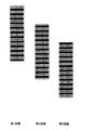
それ故に、本発明に従って、各印刷段階、すなわち、プリントヘッドの主走査方向への横断毎に、プリントヘッドにおける複数の利用可能な放出要素のアクティブ部分が選択される。特に、図5aにも表されるように、印刷段階が左から右へのプリントヘッドの横断と同時に起こる場合に、アクティブ部分は、12個の利用可能なノズル全てを含む。印刷段階がプリントヘッドの右から左への横断と同時に起こる場合には、アクティブ部分は、プリントヘッドの中央に位置する6個のノズルを含み、一方で、下部3つのノズルに加えて上部3つのノズルは、非アクティブ部分の一部となる。この実施例では、前方への各横断におけるアクティブ部分および後方への各横断におけるアクティブ部分が選択され、前方への横断において印刷される画像の各部分のスワス幅が、後方への横断において印刷される画像の各部分のスワス幅の2倍になるようにする。一般に、奇数の印刷段階Mで画像を印刷する場合、前方への各横断におけるアクティブ部分および後方への各横断におけるアクティブ部分が選択され、前方への横断において印刷された画像の各部分のスワス幅と、後方への横断において印刷された画像の各部分のスワス幅との比率が、M+1をM−1で除したもの、あるいは、その逆になるようにする。 Therefore, in accordance with the present invention, for each printing stage, i.e., traversing the print head in the main scanning direction, an active portion of a plurality of available emitting elements in the print head is selected. In particular, as represented also in FIG. 5a, the active portion includes all 12 available nozzles when the printing phase occurs simultaneously with a printhead traversal from left to right. If the printing phase occurs simultaneously with the printhead crossing from right to left, the active part contains six nozzles located in the center of the printhead, while the top three nozzles in addition to the bottom three nozzles. The nozzle becomes part of the inactive portion. In this example, the active part at each forward crossing and the active part at each back crossing are selected and the swath width of each part of the image printed at the front crossing is printed at the back crossing. To be twice the swath width of each part of the image. In general, when printing an image with an odd number of printing stages M, the active part at each forward traverse and the active part at each backward traverse are selected and the swath width of each part of the printed image at the forward traverse And the swath width of each part of the printed image in the rearward crossing is set to M + 1 divided by M-1 or vice versa.
図4aに表されるようなプリントマスクを用いて、各横断におけるプリントヘッドの非アクティブ部分が、300dpiの解像度で完全に満たされたビットマップを作り出す点に留意すべきである。従って、これら非アクティブ部分のノズルは、位置誤差が全くないか、あるいは、せいぜい1印刷ピッチの絶対位置誤差で、如何なる不合格ノズルをも補正するように使用されてもよい。 It should be noted that with a print mask as represented in FIG. 4a, the inactive portion of the printhead at each traverse creates a fully filled bitmap at 300 dpi resolution. Accordingly, these inactive nozzles may be used to correct any rejected nozzles with no positional error or at most an absolute positional error of one print pitch.
図4aに表されるのと同じプリントマスクを使用して第1印刷段階を実行すると、図5bに概略的に表されるようなドットパターンが得られる。第1印刷段階が実行された後、画像受け入れ部材は、印刷ピッチの8倍の距離に渡って前進させられる。移動ステップ後、第2印刷段階が実行される。この第2印刷段階、すなわち、右から左への横断において、アクティブ部分は、プリントヘッドの中央に位置する6つのノズルを包含し、一方、非アクティブ部分は、上部3つおよび下部3つの双方のノズルを包含する。図5bに概略的に表されるようなドットパターンが得られる。第2印刷段階の実行後、画像受け入れ部材は、印刷ピッチの8倍の距離に渡って再び前進させられる。 When the first printing stage is performed using the same print mask as represented in FIG. 4a, a dot pattern as schematically represented in FIG. 5b is obtained. After the first printing stage is performed, the image receiving member is advanced over a distance of 8 times the printing pitch. After the moving step, the second printing stage is executed. In this second printing stage, i.e. right-to-left traversal, the active part contains six nozzles located in the center of the print head, while the inactive part consists of both the top three and the bottom three. Includes a nozzle. A dot pattern as schematically represented in FIG. 5b is obtained. After execution of the second printing stage, the image receiving member is advanced again over a distance of eight times the printing pitch.
第3印刷段階において、この場合左から右への横断において、再度プリントヘッドの全てが使用される。その後、画像受け入れ部材は再度前進させられるが、このときは、印刷ピッチの11倍の距離に渡って前進させられる。その後、次の印刷段階が実行される。これは、再度の第1印刷段階であるが、この場合、右から左への横断であり、それ故に、プリントヘッドの中央の6個のノズルのみが使用される。実際には、上述の印刷段階である、第1、第2および第3印刷段階、並びに、関連する前進ステップである、8印刷ピッチ、8印刷ピッチおよび11印刷ピッチの前進ステップが、画像全体が印刷されるまで繰り返される。図5において観察されるように、前方および後方への横断におけるアクティブ部分の選択は、それぞれ、画像受け入れ部材の移動ステップを考慮に入れ、画像が描画される画像受け入れ部材の一部の副走査方向における位置毎で、プリントヘッドの横断方向が、横断するプリントヘッドのアクティブ部分への最初の暴露毎に、同じになるようにする。 In the third printing stage, all of the printheads are again used, in this case from left to right crossing. Thereafter, the image receiving member is advanced again, but at this time, it is advanced over a distance of 11 times the printing pitch. Thereafter, the next printing stage is executed. This is the first printing stage again, but in this case a right-to-left traversal and therefore only the six nozzles in the center of the print head are used. In practice, the first, second and third printing stages, as described above, and the associated advance steps, 8 print pitch, 8 print pitch and 11 print pitch advance steps, Repeat until printed. As observed in FIG. 5, the selection of the active part in the forward and backward traversal takes into account the moving step of the image receiving member, respectively, and the sub-scan direction of the part of the image receiving member on which the image is drawn For each position at, the printhead transverse direction is the same for each initial exposure to the active portion of the traversing printhead.
1 ローラ
2 画像受け入れ部材
3 プリントヘッド
4 キャリッジ
5、6 ロッド
7 放出要素
A、B 矢印
11、12 位置
13、14、15、16 画像点
DESCRIPTION OF
Claims (8)
当該印刷装置は、
少なくとも1つのプリントヘッドであって、該プリントヘッドは、主走査方向に前記画像受け入れ部材を横断して往復移動可能であり、かつ、各印刷段階において前記画像受け入れ部材上にマーキング材料のドットを形成して画像の一部を印刷するための複数の放出要素を有し、各印刷段階は、作動状態にある当該プリントヘッドの主走査方向への横断のそれぞれに対応するところのプリントヘッドと、
各印刷段階の後、副走査方向での所定距離にわたる前記プリントヘッドと前記画像受け入れ部材との間の相対移動を実現するための移動手段と、を有し、
当該印刷装置は、さらに、
前記主走査方向における前記プリントヘッドの前記横断毎に、前記複数の放出要素の中からアクティブとなる放出要素を選択し、かつ、その駆動を制御するための制御手段であり、前記画像が描画される前記画像受け入れ部材の一部の前記副走査方向における、少なくとも部分的に二回以上マーキング材料を受け入れるドット受け入れ位置のそれぞれにおいて、該ドット受け入れ位置のそれぞれが一回目のマーキング材料を受け入れるときの前記プリントヘッドの前記横断の方向が同じになるように、前記アクティブとなる放出要素のそれぞれを選択する制御手段を有する、
ことを特徴とする印刷装置。 A printing device for printing an image on an image receiving member through a plurality of printing stages,
Those said printing apparatus,
What least one printhead der, the print head is in the main scanning direction the image receiving member permits reciprocated across and marking material prior Symbol image-receiving member on Te each printing stage odor a plurality of emitting elements for forming a dot to print a portion of the image, each printing stage, the print where corresponding to each of the traverse of the main scanning direction of the Ah Ru the print head in operation Head ,
After each printing step, anda moving means for realizing a relative movement between the print head and the image-receiving member over a predetermined distance in the sub-scanning direction,
The printing apparatus further includes:
Each said traverse of the print head in the main scanning direction, and select the emission element which becomes active from the plurality of emitting elements, and a control means for controlling the driving movement of its said image In each of the dot receiving positions for receiving the marking material at least partially twice in the sub-scanning direction of the part of the image receiving member to be drawn , each of the dot receiving positions receives the first marking material wherein as the direction of the transverse becomes the same printhead, having a control means for selecting each of the emitting elements serving as the active,
A printing apparatus characterized by that.
ことを特徴とする請求項1に記載の印刷装置。 Emission element as a selected active against cross in one direction is different from the emission element which becomes active selected for cross in the other direction,
The printing apparatus according to claim 1.
ことを特徴とする請求項1または2に記載の印刷装置。 When printing subsequent portions of an image, a series of printing steps and corresponding transfer steps are executed to repeat, the moving step, and the print head over a predetermined distance in time between each successive printing stages Defined by relative movement with respect to the image receiving member;
The printing apparatus according to claim 1, wherein:
ことを特徴とする請求項3に記載の印刷装置。 Each of the moving steps is defined by a relative movement over the same constant distance;
The printing apparatus according to claim 3.
ことを特徴とする請求項1乃至4の何れか一項に記載の印刷装置。 Each release element serving as the active, the product of the number of the release element pitch of the emission element as a said active is selected to be an integer multiple of the non-zero of the predetermined distance,
The printing apparatus according to claim 1 , wherein the printing apparatus is a printer.
ことを特徴とする請求項1乃至5の何れか一項に記載の印刷装置。 When printing an image with an even number of printing stages, the active emitting elements in one direction of traversing are collected at one end of the print head, while the active emitting elements in the other direction of traversing Is collected at the other end of the print head,
The printing apparatus according to claim 1 , wherein the printing apparatus is a printer.
ことを特徴とする請求項1乃至6の何れか一項に記載の印刷装置。 When printing an image with an even number of printing stages, the and each comprising emitting elements active, as the swath width of each of the printing stages are equal, are selected,
The printing apparatus according to claim 1 , wherein the printing apparatus is a printer.
ことを特徴とする請求項1乃至5の何れか一項に記載の印刷装置。 When printing an image in the print stage of odd M, release element serving as the active in the horizontal cross-sectional in one direction, and release element to be the active in each of the cross in the other direction is to the one direction the ratio of the swath width in the horizontal cross-sectional of the swath width and said other direction in each of the crossing is either obtained by dividing the M + 1 at M-1, or such that its inverse is selected,
Printing apparatus according to any one of claims 1 to 5, characterized in that.
Applications Claiming Priority (2)
| Application Number | Priority Date | Filing Date | Title |
|---|---|---|---|
| EP05100024.8 | 2005-01-04 | ||
| EP05100024 | 2005-01-04 |
Publications (2)
| Publication Number | Publication Date |
|---|---|
| JP2006188061A JP2006188061A (en) | 2006-07-20 |
| JP4818724B2 true JP4818724B2 (en) | 2011-11-16 |
Family
ID=34938478
Family Applications (1)
| Application Number | Title | Priority Date | Filing Date |
|---|---|---|---|
| JP2005378940A Active JP4818724B2 (en) | 2005-01-04 | 2005-12-28 | Printing apparatus and control method thereof |
Country Status (4)
| Country | Link |
|---|---|
| US (1) | US7559624B2 (en) |
| JP (1) | JP4818724B2 (en) |
| AT (1) | ATE373568T1 (en) |
| DE (1) | DE602005002528T2 (en) |
Families Citing this family (4)
| Publication number | Priority date | Publication date | Assignee | Title |
|---|---|---|---|---|
| EP1882597B1 (en) * | 2006-07-24 | 2009-06-24 | Océ-Technologies B.V. | Method of producing a tiled print product |
| JP2008068613A (en) * | 2006-07-24 | 2008-03-27 | Oce Technologies Bv | Method of manufacturing tile printed work |
| WO2008129919A1 (en) * | 2007-04-18 | 2008-10-30 | Konica Minolta Medical & Graphic, Inc. | Ink-jet recorder and ink-jet recording method |
| JP5955022B2 (en) * | 2011-03-16 | 2016-07-20 | キヤノン株式会社 | Inkjet recording device |
Family Cites Families (4)
| Publication number | Priority date | Publication date | Assignee | Title |
|---|---|---|---|---|
| US5070345A (en) * | 1990-02-02 | 1991-12-03 | Dataproducts Corporation | Interlaced ink jet printing |
| US6170932B1 (en) * | 1997-05-20 | 2001-01-09 | Seiko Epson Corporation | Printing system, method of printing, and recording medium to realize the method |
| JP3984706B2 (en) * | 1998-07-03 | 2007-10-03 | キヤノン株式会社 | Image recording device |
| JP4343481B2 (en) | 2001-02-06 | 2009-10-14 | キヤノン株式会社 | Inkjet recording apparatus and inkjet recording method |
-
2005
- 2005-12-27 DE DE602005002528T patent/DE602005002528T2/en active Active
- 2005-12-27 AT AT05112995T patent/ATE373568T1/en not_active IP Right Cessation
- 2005-12-28 JP JP2005378940A patent/JP4818724B2/en active Active
-
2006
- 2006-01-03 US US11/322,321 patent/US7559624B2/en active Active
Also Published As
| Publication number | Publication date |
|---|---|
| US7559624B2 (en) | 2009-07-14 |
| JP2006188061A (en) | 2006-07-20 |
| US20060146078A1 (en) | 2006-07-06 |
| DE602005002528T2 (en) | 2008-06-19 |
| DE602005002528D1 (en) | 2007-10-31 |
| ATE373568T1 (en) | 2007-10-15 |
Similar Documents
| Publication | Publication Date | Title |
|---|---|---|
| US7699436B2 (en) | Ink jet printing method and ink jet printing apparatus | |
| JP5969029B2 (en) | Inkjet printing method and printer | |
| US6565191B1 (en) | Method of color shingling to reduce visible printing defects | |
| JPH10157172A (en) | Edge enhancement depletion method related to excessive ink drop for attainment of high-resolution x/y axis address assigning performance in ink-jet print | |
| JP4818724B2 (en) | Printing apparatus and control method thereof | |
| JP4818723B2 (en) | Printing device | |
| US8256875B2 (en) | Two pass print mode method and apparatus for limiting wind-related print defects | |
| JPH10157094A (en) | Color ink jet reduction method of oversized ink droplet for achieving high resolution x/y axis address designating capability | |
| EP1676710B1 (en) | Printing device and control method thereof | |
| JP6815511B2 (en) | Image processing equipment and methods, programs and image recording equipment | |
| US6695426B2 (en) | Ink jet printer improved dot placement technique | |
| JP4271502B2 (en) | Printing apparatus and control method thereof | |
| US6357856B1 (en) | Printing with a vertical nozzle array head | |
| JP3488304B2 (en) | Inkjet printer control method | |
| JP6815505B2 (en) | Image processing equipment and methods, dither mask set, and image recording equipment | |
| JPH10157171A (en) | Region filling depletion method independently of plot for high-resolution x/y axis address assigning performance in ink-jet print | |
| JP5783948B2 (en) | Color image forming apparatus | |
| EP1676705B1 (en) | Printing device | |
| EP1375169B1 (en) | Printing device and control method thereof | |
| JP2013212659A (en) | Printing device and printing method | |
| JP2004160863A (en) | Printing controller, printing control method, printing system and printing control program | |
| JP2004066821A (en) | Ink jet recording device, ink jet recording method, and program | |
| JP2004066725A (en) | Bi-directional printing with consideration to mechanical vibration of print head | |
| JP3707321B2 (en) | Color printing apparatus and printing method using vertical array head, and print head therefor | |
| JP2000238249A (en) | Ink jet recording apparatus |
Legal Events
| Date | Code | Title | Description |
|---|---|---|---|
| A621 | Written request for application examination |
Free format text: JAPANESE INTERMEDIATE CODE: A621 Effective date: 20081205 |
|
| A131 | Notification of reasons for refusal |
Free format text: JAPANESE INTERMEDIATE CODE: A131 Effective date: 20110104 |
|
| A521 | Request for written amendment filed |
Free format text: JAPANESE INTERMEDIATE CODE: A523 Effective date: 20110308 |
|
| A131 | Notification of reasons for refusal |
Free format text: JAPANESE INTERMEDIATE CODE: A131 Effective date: 20110510 |
|
| TRDD | Decision of grant or rejection written | ||
| A01 | Written decision to grant a patent or to grant a registration (utility model) |
Free format text: JAPANESE INTERMEDIATE CODE: A01 Effective date: 20110823 |
|
| A01 | Written decision to grant a patent or to grant a registration (utility model) |
Free format text: JAPANESE INTERMEDIATE CODE: A01 |
|
| A61 | First payment of annual fees (during grant procedure) |
Free format text: JAPANESE INTERMEDIATE CODE: A61 Effective date: 20110831 |
|
| FPAY | Renewal fee payment (event date is renewal date of database) |
Free format text: PAYMENT UNTIL: 20140909 Year of fee payment: 3 |
|
| R150 | Certificate of patent or registration of utility model |
Ref document number: 4818724 Country of ref document: JP Free format text: JAPANESE INTERMEDIATE CODE: R150 Free format text: JAPANESE INTERMEDIATE CODE: R150 |
|
| R250 | Receipt of annual fees |
Free format text: JAPANESE INTERMEDIATE CODE: R250 |
|
| R250 | Receipt of annual fees |
Free format text: JAPANESE INTERMEDIATE CODE: R250 |
|
| R250 | Receipt of annual fees |
Free format text: JAPANESE INTERMEDIATE CODE: R250 |
|
| R250 | Receipt of annual fees |
Free format text: JAPANESE INTERMEDIATE CODE: R250 |
|
| R250 | Receipt of annual fees |
Free format text: JAPANESE INTERMEDIATE CODE: R250 |
|
| R250 | Receipt of annual fees |
Free format text: JAPANESE INTERMEDIATE CODE: R250 |
|
| R250 | Receipt of annual fees |
Free format text: JAPANESE INTERMEDIATE CODE: R250 |
|
| R250 | Receipt of annual fees |
Free format text: JAPANESE INTERMEDIATE CODE: R250 |
|
| R250 | Receipt of annual fees |
Free format text: JAPANESE INTERMEDIATE CODE: R250 |
|
| R250 | Receipt of annual fees |
Free format text: JAPANESE INTERMEDIATE CODE: R250 |