JP3984706B2 - Image recording device - Google Patents
Image recording device Download PDFInfo
- Publication number
- JP3984706B2 JP3984706B2 JP18918098A JP18918098A JP3984706B2 JP 3984706 B2 JP3984706 B2 JP 3984706B2 JP 18918098 A JP18918098 A JP 18918098A JP 18918098 A JP18918098 A JP 18918098A JP 3984706 B2 JP3984706 B2 JP 3984706B2
- Authority
- JP
- Japan
- Prior art keywords
- recording
- mask pattern
- image
- printing
- mask
- Prior art date
- Legal status (The legal status is an assumption and is not a legal conclusion. Google has not performed a legal analysis and makes no representation as to the accuracy of the status listed.)
- Expired - Fee Related
Links
Images


Description
【0001】
【発明の属する技術分野】
本発明は、被記録材にインク滴を吐出して画像を記録するインクジェット方式の画像記録装置に関する。
【0002】
【従来の技術】
近年、オフィスオートメーション化が進みパーソナルコンピュータ等の普及に伴い、パーソナルコンピュータ上のディジタル画像を記録するのにインクジェット方式のプリントヘッドを用いたインクジェットプリンタが急速に普及している。
【0003】
また、当該ディジタル画像の印字時間の短縮化や出力画像の高画質化のために、複数の記録素子を集積配列し、インク吐出口やインク流路を高密度に集積した記録ヘッド(以下、マルチヘッド)が主流となっている。
【0004】
さらに、画像のカラー化に対応させるため、上記マルチヘッドを複数備えたものが一般的になっている。
【0005】
しかし、多色インクを用いたカラー画像記録が一般化したことにより、モノクロのみで記録した場合の画質に加えて、発色性、再現性、階調性、一様性なども画像品位に関する重要な要素となっている。
【0006】
特に、カラー画像記録の一様性に関しては、マルチヘッドの製造工程で生じるノズル単位の僅かなバラツキが各ノズルの印字精度に悪影響を及ぼし、印字時のインクの吐出量や吐出方向にバラツキを生じさせるのである。この製造工程におけるバラツキが最終的に記録画像の濃度ムラとなって画像品位を劣化させる原因となるのである。
【0007】
そこで、ノズルのバラツキに起因する濃度ムラの防止対策として、例えば、特開昭60−107975号公報では、マルチヘッドを主走査方向に複数回スキャンさせながら画像を記録する方法が提案されている。
【0008】
この方法によれば、複数のノズルが並ぶマルチヘッドの全ノズル幅の領域の記録を完了させるためにマルチヘッドを主走査方向に3回スキャンさせ、マルチヘッド幅の全画素の半分ずつの領域の記録をそれぞれ2回のスキャンで完了させている。この場合、マルチヘッドの全ノズルはヘッドの上半分と下半分のグループに分けられ、1つのノズルが1回のスキャンで形成するドットは、画像データを所定の画像データ配列に従って半分に間引いたものに対応する。そして2回目のスキャン時において、残る半分の画像データに相当するドットを形成することで画像出力を完了させている。
【0009】
上記記録方法では、1回目のスキャンと2回目のスキャンとで分割された画像データが互いに補完し合うように、通常、画像データ配列(マスクパターン)に従って画像を記録する。このマスクパターンは、図21(a)、(b)に示すように、縦横の画素同士が千鳥格子になるようなパターンを用いるのが一般的である。そして、1回目のスキャンでは単位記録領域において図21(a)のパターンを用いて間引いた画像データに対応するドットを形成し、2回目のパターンでは、図21(b)に示す反転千鳥格子状のパターンを用いて間引いた画像データに対応するドットを形成する。このように、2回のスキャンにより単位記録領域の画像の出力を行うのである。
【0010】
以上説明したように、異なる2種類のノズルを使用して単位記録領域内の画像が記録されので、濃度ムラの無い高品位な画像を記録することが可能となる。
【0011】
図2は、従来の画像記録装置の概略構成を示す斜視図である。
【0012】
図2に示すように、印字開始前にホームポジション位置にあるキャリッジ202は印字開始命令を受けると、主走査方向(X軸方向)に往復運動させることによりマルチヘッド206上のn個のマルチノズルを、分割された被記録材の記録領域上で往復させる。往運動による被記録材へのインク吐出が終了してキャリッジ202がキャリッジの反転位置まで達すると、キャリッジ202はホームポジション201へ向かって復運動を開始する。キャリッジ202がホームポジション側のキャリッジ反転位置に達すると、キャリッジ202は再び往運動を開始する。
【0013】
このキャリッジ202の往復運動による1回目の印字が終了してから2回目の印字が始まる前までに、被記録材搬送ローラ203と被記録材排出ローラ205が回転することによって被記録材204が搬送される。この送り量は、分割された記録領域幅だけ主走査方向(Y方向)に送り出されるように制御される。このようにして、キャリッジの1スキャン毎にマルチヘッドによる印字と被記録材の搬送を繰り返し行うことで画像出力が完了する。
【0014】
図3は、一般的なインクジェット方式の画像記録装置を示すブロック構成図である。
【0015】
図3に示すように、301はCPUで、その内部バスにはROM302とRAM303が接続される。CPU301はROM302からプログラムを読み出し、RAM303に対してリード/ライトを繰り返すことでプログラムを実行する。304は画像記録装置と不図示の外部ホスト装置との間でコマンド転送や画像データ転送を行うインタフェースであり、CPU301と後述するバンドメモリ307に接続される。305は各種キーによる入力操作や動作状態を表示するための操作・表示部でありCPU301に接続される。307は、バンドメモリであり、インタフェース304から印字のための画像データが転送され、CPU301の制御によって、1バンド分の画像データとして所定幅に分割された記録領域の画像記録に必要な画像データがストアされる。バンドメモリ307の出力は、マルチパスデータ処理部308に入力される。マルチパスデータ処理部308は、CPU301の制御によって、分割された印字領域の画像記録を複数回のスキャンで完了するように画像データの間引き処理を行ない、1スキャン分の画像データを生成し、ヘッドコントローラ309に出力する。309はヘッドコントローラであり、その出力はマルチヘッド310に接続される。ヘッドコントローラ309は、CPU301の制御によって、キャリッジが1スキャンの動作を行う間に、所定幅に分割された印字領域の画像記録が行われるように、マルチヘッド310を駆動する。マルチヘッド310は、ヘッドコントローラ309により制御され、ヘッド上に形成された複数のインク吐出口からインクを飛翔させて、キャリッジ動作と同期されて1スキャン分の画像記録を実行する。
【0016】
図6は、2パスに設定されたマルチパス印字時のヘッド位置と記録画像を示す図である。
【0017】
図6に示すように、2パス印字では、ヘッドを搭載したキャリッジが被記録材上を往復しながらインクを吐出することで画像を記録し、1回のスキャン動作毎に1/2バンド幅ずつ被記録材の搬送動作を行なう。1回のスキャン動作では、1バンド分の画像データのうち近接画素について間引かれた画像データを記録する。そして、2回のスキャンにより1バンド分の画像記録を完了させる。
【0018】
【発明が解決しようとする課題】
しかしながら、上記従来例のように記録領域を分割して記録しても濃度ムラの弊害は完全には解消されていない。
【0019】
例えば、印字動作中にインク供給動作やヘッド回復動作が必要になり、1回目のスキャン終了から2回目のスキャン開始までに時間がかかってしまう場合には、特に高デューティ印字では印字時間差に起因する濃度変化が濃度ムラ(時間差ムラ)として現れることが知られている。
【0020】
ここで、図9、10を参照して印字時間差による濃度ムラについて説明する。図9、10は、所定の記録領域に対する画像記録を2回のスキャンで完了させる場合に、2回のスキャンの時間間隔が短い場合と長い場合とについて被記録材に対するインクの浸透と定着の様子を模式的に表した図である。
【0021】
図9、10において、801はインク滴、802は被記録材である。1回目のスキャンで被記録材802に浸透したインク滴801aは、紙面に垂直な方向および紙面に広がる方向へ浸透し、インク成分である染料などの色素が被記録材と物理的化学的に結合する。
【0022】
図9は、1パス目と2パス目との時間間隔が短い場合を示す図である。
【0023】
図9において、1パス目の印字後、2パス目のインク滴801bも被記録材に垂直な方向と、被記録材表面に広がる方向に浸透するが、先に着弾した801aが定着した領域にはあまり浸透・定着しない。その原因は、先に着弾したインク滴801aが未だ浸透しつつある状態にあること、被記録材とインク成分との化学的な結合が有限であることが考えられる。そのため、後から着弾したインク滴801bは、先に着弾したインク滴801aが浸透した領域のさらに下の方へ浸透・定着することになる。
【0024】
図10は、1パス目と2パス目との時間間隔が長い場合を示す図である。
【0025】
図10において、後から着弾したインク滴801bは、先に着弾して浸透・定着している領域に比較的多く浸透する。これは、先に着弾したインク滴801aが十分浸透して広がり、或いはその揮発成分が蒸発したため、単位体積当たりのインク滴801aの量が減少し、後から着弾したインク滴801bが浸透できるようになったためではないかと考えられる。
【0026】
即ち、1パス目と2パス目との時間間隔が長い方が被記録材の表面付近に定着するインク量、つまり染料などの色素やインク成分が多く残る。また、その濃度は、被記録材の表面付近に定着する色素の光の吸収に対応するので、時間間隔が長くなるほうが濃度が濃くなってしまう。
【0027】
このように、分割記録方法により画像を記録する場合、途中パスでの印字が中断されると、中断の前後の画像に濃度ムラを生じてしまうのである。
【0028】
本発明は、上述の課題に鑑み、その目的は、バンド分割による記録を行う際に印字が中断されても濃度ムラを生じないで、インク供給やヘッド回復など他動作を行ない、その後印字動作を再開できる画像記録装置及び画像記録方法を提供することである。
【0029】
【課題を解決するための手段】
上述の課題を解決し、目的を達成するために、本発明の画像記録装置は、複数のインク吐出口を備えるヘッドを被記録材の単位記録領域に対して3回走査させることにより画像を記録する画像記録装置において、前記被記録材を搬送する搬送手段と、各走査で記録に用いるインク吐出口を定めるための第2のマスクパターンを選択するパターンセレクタと、前記第2のマスクパターンと、前記単位記録領域に記録すべき画像データを前記3回の走査に分けるための第1のマスクパターンとに基づき、前記画像データを間引いて各走査の間引き画像データを生成する生成手段と、前記搬送手段、前記パターンセレクタ及び前記ヘッドを制御することにより、前記間引き画像データに基づいて記録中断前及び記録再開後における記録を実行させる制御手段と、を有し、前記制御手段は、(A)記録中断直前の2回の走査の間で前記被記録材を搬送し、記録再開直後の2回の走査の間で前記被記録材を搬送しないよう前記搬送手段を制御し、且つ記録中断直前に記録が完了される単位記録領域に対する当該記録中断直前の2回の走査で異なるインク吐出口群を用いるように前記第2のマスクパターンを選択し、記録再開直後に記録が開始される単位記録領域に対する当該記録再開直後の2回の走査で同一のインク吐出口群を用いるように前記第2のマスクパターンを選択するよう前記パターンセレクタを制御することにより、前記記録中断前及び記録再開後における記録を実行させる第1の記録動作と、(B)記録中断直前の2回の走査の間で前記被記録材を搬送せず、記録再開直後の2回の走査の間で前記被記録材を搬送するよう前記搬送手段を制御し、且つ記録中断直前に記録が完了される単位記録領域に対する当該記録中断直前の2回の走査で同一のインク吐出口群を用いるように前記第2のマスクパターンを選択し、記録再開直後に記録が開始される単位記録領域に対する当該記録再開直後の2回の走査で異なるインク吐出口群を用いるように前記第2のマスクパターンを選択するよう前記パターンセレクタを制御することにより、前記記録中断前及び記録再開後における記録を実行させる第2の記録動作と、を選択的に実行可能である。
【0031】
【発明の実施の形態】
以下に、本発明に係る実施の形態について添付図面を参照して詳細に説明する。
[第1の実施形態]
図4は、本発明に係る代表的な実施形態のインクジェット方式の記録ヘッドを搭載する画像記録装置の概略ブロック図である。
【0032】
図4に示すように、401はCPUで、その内部バスにはROM402とRAM403が接続される。CPU401はROM402からプログラムを読み出し、RAM403に対してリード/ライトを繰り返すことでプログラムを実行する。404は不図示の外部ホスト装置との間でのコマンドや画像データ転送を行うインタフェースであり、CPU401と後述するバンドメモリ407に接続される。405は、本装置に対する各種キーの入力操作や動作状態を表示する操作・表示部であり、CPU401に接続される。406は、後述するマスクパターンセレクタであり、CPU401に接続されて制御され、その出力は後述するマルチパスデータ処理部408に接続される。407はバンドメモリであり、インタフェース404から印字のための画像データが転送され、CPU401の制御によって、1バンド分の画像データとして所定幅に分割された領域の印字に必要な画像データがストアされる。バンドメモリ407の出力は、マルチパスデータ処理部408に入力される。マルチパスデータ処理部408は、CPU401の制御によって、分割された領域の印字を複数回のスキャンで完了するように画像データの間引き処理を実行し、1スキャン分の画像データを生成し、ヘッドコントローラ409に出力する。409はヘッドコントローラであり、その出力はマルチヘッド410に入力される。ヘッドコントローラ409は、CPU401の制御によって、キャリッジが1スキャン動作を行う間に、所定幅に分割された領域の印字が実行されるようにマルチヘッド410を駆動する。マルチヘッド410は、ヘッドコントローラ409により制御されて、記録ヘッド上に形成された複数のインク吐出口からインクを飛翔させて、キャリッジ動作と同期しながら1スキャン分の印字を実行する。
【0033】
次に、本実施形態の画像記録装置が2回の走査によって所定幅の領域の印字を実行する動作(2パス印字)について説明する。
【0034】
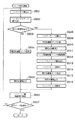
図1は、2パス印字動作を休止及び再開させた場合のヘッド位置とインク吐出口の分布位置の変化を示す図である。図5は、CPU401の制御動作を示すフローチャートである。
【0035】
図1、図4及び図5において、先ず、インタフェース404を経由して印字要求コマンドがCPU401に入力されると、CPU401は1バンド分の画像データをバンドメモリ407に書き込む(ステップS501)。
【0036】
次に、マルチパスデータ処理部408は、バンドメモリ407から1バンド分の全ての画像データを読み出す(ステップS502)。次に、CPU401は、インク残量検知処理の結果フラグやスキャン行数をアップカウントするカウンタを参照し、印字動作の中断要求の有無を判定する。ステップS503で中断要求がなければ(ステップS503でNO)、マルチパスデータ処理部408において2パス印字を行うための間引き処理を行う(ステップS504)。この間引き処理はバンドメモリ407から読み出した画像データを所定のマスクパターンでマスクすることにより実現される。
【0037】
本実施形態では、2パス印字の1回目のスキャンで印字する画像データを間引くためのマスクパターンを図21(a)に示す千鳥パターンとし、2回目のスキャンで印字する画像データを間引くためのマスクパターンを図21(b)に示す反転千鳥パターンとする。また、記録ヘッドは、説明の簡略化のため8個のインク吐出口が1列に並設され、千鳥パターンマスクで1画素置きに4画素のデータを間引き、反転千鳥パターンマスクで前回間引かれた4画素のデータが間引かれるとする。
【0038】
次に、間引かれた画像データをヘッドコントローラ409に出力し、キャリッジを主走査方向にスキャンさせながらマルチヘッド410からインクを吐出させて被記録材上に画像を印字する(ステップS505)。ステップS505におけるヘッド位置と吐出ノズルの領域は、図1の領域Aとなり、全吐出口のうち千鳥パターン或いは反転千鳥パターンにより間引かれた領域が1スキャン分の全領域に分布する。
【0039】
そして、1スキャン分のインク吐出による印字が終了したら、被記録材の1/2バンド幅だけ記録材を搬送する(ステップS506)。ステップS506では、ヘッド位置は図1に示す領域Aよりも1/2バンド幅だけ前進した領域Bになる。
【0040】
記録材1枚分の印字が全て完了していなければ(ステップS507でNO)、ステップS501に戻り、インタフェース404から次の画像データ転送要求を出力して、外部ホスト装置などから新たに転送されてくる画像データをCPU401の制御によってバンドメモリ407に書き込む。
【0041】
以下、ステップS501からステップS507までの動作を繰り返すことで、図7及び図8に示すように全ての領域について画像データが転送され、2パス印字動作が完了する。ここで、図7及び図8は、被記録材に2パス印字を行なった場合の出力画像を示す図である。
【0042】
図示しないが、CPU401は、ソフトウェアの割込み処理やハードウェアによるカウンタ等を用いて、インクタンク内のインク残量検知処理や、所定量のインクを消費する度にヘッド回復処理を実行するための総印字ドット数の計数処理等、印字を継続するための動作環境を監視するプログラムを印字動作プログラムと共に実行している。そして、CPU401は、インク供給やヘッド回復動作などによって印字動作を中断する必要がある場合に、先ず印字動作の中断要求フラグをセットする。
【0043】
ステップS501からステップS507による2パス印字の実行中に、印字動作の中断を要求するフラグがセットされていることをCPU401が判定したならば(ステップS503でYES)、CPU401はマスクパターンセレクタ406でデータ間引き処理のためのマスクパターンを切り換える(ステップS508)。
【0044】
ここで、マスクパターンについて図15〜図17を参照して説明する。
【0045】
マルチパスデータ処理部408では、画像データを図15(a)のマスクパターンによりマスクすることで間引き画像データが生成される。この時、マスクパターンセレクタ406では、CPU401の制御によって図15(b)のマスクパターンが選択されている。そして、マルチパスデータ処理部408では、図15(a)と図15(b)のマスクパターンを掛け合わせた図15(c)のマスクパターンが間引き処理のためのマスクパターンとして用いられ、間引き画像データが生成される。
【0046】
ところが、ステップS508でのマスクパターンの切り換えは、マスクパターンセレクタ406により図16(b)のマスクパターンが選択される。そして、マルチパスデータ処理部408において図16(a)のマスクパターンと図16(b)のマスクパターンとを掛け合わせた図16(c)のパターンが新たなマスクパターンとして使用され、間引き処理が行われる(ステップS509)。ここで、図16(b)のマスクパターンは、マルチヘッド410による2パス印字の2/2パス目の印字動作を禁止するように画像データを間引くためのパターンである。
【0047】
さらに、CPU401は間引き処理後の画像データをヘッドコントローラ409に出力し、マルチヘッド410のインク吐出口からインクを吐出させて1/2パス目の印字を完了させる(ステップS510)。これは、新たな2/2パス目の領域に対する印字を禁止して1/2パス目である半バンドの印字を行うことに相当する。このように出力された画像を図8に示す。2パス印字の2回目のスキャン印字が完了すると2/2パス目の画像の印字が完了され,この時のヘッド位置と吐出ノズル領域の関係は、図1の領域Bとなり、1バンド分の画像領域のうち上半分の領域のみの画像の印字が実行される。
【0048】
その後、印字動作は休止状態になり図1の領域Cに移行する。CPU401は、所定のヘッド回復処理やインク供給処理などを実行した後(ステップS511)、印字中断要求フラグをリセットする。
【0049】
ステップS511のインク供給処理やヘッド回復処理が終了して印字を再開する場合には、CPU401の制御によって、図4のバンドメモリ407から1バンド分の画像データを再び読み出し(ステップS512)、マスクパターンセレクタ406においてマスクパターンを図17(b)のパターンに変更する(ステップS513)。図17(b)のマスクパターンはステップS508において変更したマスクパターンと補完し合うように反転されたマスクパターンであって、2パス印字の1/2パス目の印字を行わないように画像データを間引くためのパターンである。
【0050】
次に、マルチパスデータ処理部408において、図17(a)と図17(b)のマスクパターンが掛け合わされ、図17(c)の新たなマスクパターンにより画像データが間引かれる(ステップS514)。そして、間引かれた画像データに対応したヘッド駆動信号がヘッドコントローラ409に出力され、マルチヘッド410により被記録材に間引き画像が出力される(ステップS515)。この時のヘッド位置と吐出ノズル領域の関係は図1の領域Dの如くなる。領域Dのヘッド位置と領域Bのヘッド位置とは同じ位置に存在するが、インク吐出口の領域は、領域Bと相互補完の関係にあたる1バンド分のうち下半分の領域となる。
【0051】
そして、再びステップS506において被記録材の搬送動作を実行することによって、ヘッド位置は図1の領域Eとなり、その後は通常の2パス印字が継続される。
【0052】
このようにして、印字中断及び再開の前後で2パス印字を完了させることによって1パス目と2パス目の画像間に濃度ムラが発生しないように、また、ステップS510での間引き画像の出力のためのキャリッジのスキャン動作とステップS515におけるキャリッジ動作との間で、被記録材の搬送動作が行われないように印字動作を中断させることで、出力画像の切れ目における画像のつなぎ目を目立たなくすることが可能となる。
【0053】
ステップS515での印字が終了すると、CPU401は、通常の2パス印字を連続して実行するために、マスクパターンセレクタ406において図15(b)のマスクパターンを選択し、このマスクパターンを使用してステップS501からステップS507までの処理を順次繰り返す。
【0054】
続いて、マルチパス印字の中断直前から再開直後までのマスクパターンセレクタ406によるマスクパターンの選択について説明する。
【0055】
図11は2パス印字を行なう際にマスクパターンセレクタ406において選択されるマスクパターンを示す図である。図14は、マスクパターンセレクタ406の回路構成を示す図である。
【0056】
図14に示すように、2パス印字の場合には、CPU401はマスクパターンセレクタ406のマスクパターンP1〜P3(図11参照)から所定のマスクパターンを選択する。
<2パス印字動作でのマスクパターン選択>
図11において、黒く塗りつぶされた領域が印字領域であり、白い領域はマスクされることによって印字されない領域である。図22は、図11の2パス印字動作中に印字を中断及び再開させる際のマスクパターンセレクタ406によるマスクパターンの選択と、被記録材搬送動作の連携動作を示すフローチャートである。
【0057】
先ず、通常の2パス印字動作について説明する。
【0058】
図22に示すように、マルチヘッド410の吐出口を制限するためのマスクパターンとして図11のマスクP1が選択される。そして、印字中断要求フラグを監視し(ステップS1701)、図11のマスクP1を使用して画像出力を行い(ステップS1702)、1/2バンド幅ずつ被記録材を搬送して(ステップS1703)、画像データがインタフェース404を経由して転送されていれば(ステップS1704でNO)、ステップS1701へ戻り、インタフェース404を経由した画像データ転送が終了していれば(ステップS1704でYES)、2パス印字動作を終了。
【0059】
ステップS1701からステップS1704までを繰り返すことによって2パス印字を実行中に、CPU401が印字中断要求フラグのセットを判定すると(ステップS1701でYES)、マスクパターンを図11のマスクP1からマスクP2に切り換える(ステップS1705)。
【0060】
次に、2パス印字のために間引き処理された画像データに対して図11のマスクP2によりマスクされた画像を出力する(ステップS1706)。そして、ステップS1706の後に記録材搬送動作を実行せずに、ヘッド回復動作などによる印字中断状態に移行する(ステップS1707)。その後、2パス印字動作を再開する際に、マスクパターンを図11のマスクP3に切り換えて(ステップS1708)、2パス印字のために間引き処理された画像データに対して図11のマスクP3によってマスクされた画像を出力する(ステップS1709)。次に、マスクパターンを図11のマスクP1に切り換える(ステップS1710)。そして、1/2バンド幅ずつ被記録材を搬送して(ステップS1703)、マスクP1のマスクパターンで通常の2パス印字を継続する。
【0061】
以上のように、2パス印字を行いながら印字動作を中断させる際に、途中までの印字動作一旦完了させることによって、休止時間間隔に起因する濃度ムラが生じないように2パス印字を行うことが可能となる。また、印字動作の休止から再開までの印字休止期間に被記録材の搬送動作が行われないようにマスクパターンを選択することによって、出力画像のつなぎ目で送りムラが発生しないように制御可能となる。
[第2の実施形態]
第1の実施形態では、マルチパス印字動作例として2パス印字動作を説明したが、他のパス数(例えば、3パスや4パス)の場合でも適用できる。
<3パス印字動作でのマスクパターン選択その1>
そこで、図12及び図13を参照して3パス印字動作について説明する。
【0062】
図12、13は、3パス印字動作を中断及び再開する際に、3パスによる重ね印字が完了していない領域をスキャンするインク吐出口のみからインクを吐出させ、かつ、中断から再開までの間に被記録材搬送動作を行なわないようなマスクパターンと被記録材搬送動作を示す図である。
【0063】
3パス印字の場合には、マスクパターンによりインクの吐出が可能なインク吐出口と被記録材の搬送動作の組み合わせは、図12と図13の2通り存在するが、吐出口を限定するためのマスクパターンとしては図12及び図13のP1〜P5及びP4’の6パターンから適宜選択されて印字される。
【0064】
マスクパターンセレクタ406は、これら6パターンから所定のマスクパターンを選択し、各マスクパターンで被記録材の搬送動作を適宜実行することによって、時間差ムラを生じることなく、印字を中断及び再開することが可能である。
【0065】
先ず、図12と図23を参照して図12のマスクパターンを用いた印字動作について説明する。
【0066】
図23は、図12のマスクパターンでの3パス印字中に印字を中断及び再開させる際の、マスクパターンセレクタ406によるマスクパターン選択と、被記録材搬送動作の連携動作を示すフローチャートである。
【0067】
先ず、通常の3パス印字動作について説明する。
【0068】
図23に示すように、マルチヘッド410のインク吐出口を制限するためのマスクとして図12のマスクP1が選択される。そして、印字中断要求フラグを監視し(ステップS1801)、図12のマスクP1を使用して画像を出力し(ステップS1802)、1/3バンド幅ずつ被記録材を搬送して(ステップS1803)、画像データがインタフェース404を経由して転送されていれば(ステップS1804でNO)、ステップ1801へ戻り、インタフェース404を経由した画像データ転送が終了していれば(ステップS1804でYES)、3パス印字動作による印字を終了する。
【0069】
ステップS1801からステップS1804までを繰り返すことによって3パス印字を実行中、CPU401が印字中断要求フラグのセットを判定すると(ステップS1801でYES)、マスクパターンを図12のP1からP2に切り換え、3パス印字のために間引き処理された画像データに対して図12のマスクP2によりマスクされた画像を出力する(ステップS1805)。ここで、1/3バンド幅だけ被記録材搬送を行なう(ステップS1806)。
【0070】
次に、マスクパターンを図12のP2からP3に切り換え、3パス印字のために間引き処理された画像データに対してマスクP3によりマスクされた画像を出力する(ステップS1807)。そして、ステップS1807の後に被記録材搬送動作を実行せずに、ヘッド回復動作などによる印字中断状態に移行する(ステップS1808)。その後、印字動作を再開するが、先ずマスクパターンを図12のP3からP4に切り換え、3パス印字のために間引き処理された画像データに対してマスクP4によりマスクされた画像を出力する(ステップS1809)。さらに、マスクパターンを図12のP5に切り換え、3パス印字のために間引き処理された画像データに対してマスクP5によりマスクされた画像を出力する(ステップS1810)。これで3パス印字における3パス目が完了する。その後、マスクパターンをP1に切り換えて(ステップS1811)、マスクP1を用いた通常の3パス印字を継続する。3パス印字を行う際に中断及び再開の前後でインク吐出口を限定するためのマスクパターンは、P1→P2→P3→P4→P5→P1の順に選択される。
<3パス印字動作でのマスクパターン選択その2>
次に、図13と図24を参照して図13のパターンでの印字動作について説明する。
【0071】
図24は、図13のマスクパターンでの3パス印字を実行中に印字を中断及び再開させる際の、マスクパターンセレクタ406によるマスクパターン選択と、被記録材搬送動作の連携動作を示すフローチャートである。
【0072】
先ず、通常の3パス印字動作について説明する。
【0073】
図24に示すように、マルチヘッドのインク吐出口を制限するために図13のマスクP1が選択される。そして、印字中断要求フラグを監視し(ステップS1901)、図13のマスクP1を使用して画像の出力し(ステップS1902)、1/3バンド幅ずつ被記録材を搬送する(ステップS1903)。そして、画像データがインタフェース404を経由して転送されていれば(ステップS1904でNO)、ステップS1901へ戻り、インタフェース404を経由した画像データ転送が終了していれば(ステップS1904でYES)、3パス印字動作による印字を終了する。
【0074】
ステップS1901からステップS1904までを繰り返すことによって3パス印字を実行中に、CPU401が印字中断要求フラグのセットを判定すると(ステップS1901)、マスクパターンを図13のP1からP2に切り換え、3パス印字のために間引き処理された画像データに対してマスクP2によりマスクされた画像を出力する(ステップS1905)。次に、マスクパターンをP2からP4に切り換え、3パス印字のために間引き処理された画像データに対してマスクP4によりマスクされた画像を出力する(ステップS1906)。そして、ステップS1906の後に被記録材搬送動作を実行せずに、ヘッド回復動作などによる印字中断状態に移行する(ステップS1907)。その後、印字動作を再開するが、先ずマスクパターンを図13のP4からP4’に切り換え、3パス印字のために間引き処理された画像データに対してマスクP4’によりマスクされた画像を出力する(ステップS1908)。ここで、1/3バンド幅の被記録材搬送を行なう(ステップS1909)。
【0075】
次に、マスクパターンを図13のP5に切り換え、3パス印字のために間引き処理された画像データに対してマスクP5によりマスクされた画像を出力する(ステップS1910)。これで3パス印字の3パス目が完了する。そして、マスクパターンをP1に切り換えて(ステップS1911)、マスクP1を用いた通常の3パス印字を継続する。マスクパターンの選択は、図13に示すようにP1→P2→P4→P4’→P5→P1の順に選択される。
【0076】
以上のように、図12及び図13のマスクパターンを使用した場合、3パス印字を行ないながら印字動作を中断させる場合に途中までのパス印字を一旦完了させることにより、休止時間間隔に起因する濃度ムラが生じないように3パス印字を完了させることが可能となる。
【0077】
また、印字動作の中断から再開までの印字休止期間中に被記録材の搬送動作が行われないようにマスクパターンを選択することによって、出力画像のつなぎ目で送りムラが発生しないように制御可能となる。
【0078】
尚、パターンセレクタ406は、図12及び図13に示す6種類のマスクパターンから所望のマスクを選択することもできる。
[第3の実施形態]
次に、図18〜図20を参照して4パス印字動作について説明する。
【0079】
図18〜20は、4パス印字動作を中断する際に、4パス印字が完了していない領域をスキャンするインク吐出口のみからインクを吐出させ、かつ、4パス印字再開時まで被記録材搬送動作を行なわないようなマスクパターンと被記録材搬送動作を示す図である。
【0080】
マスクパターンセレクタ406は、10種類のマスクパターンから所定のマスクパターンを選択し、各パターンで被記録材の搬送動作を適宜実行することによって、時間差ムラを生じることなく、印字の中断及び再開を実行することが可能である。
<4パス印字動作でのマスクパターン選択その1>
次に、図18と図25を参照して図18のマスクパターンを用いた4パス印字動作について説明する。
【0081】
図25は、図18の4パス印字を実行中に印字を中断及び再開させる際のマスクパターンセレクタ406によるマスクパターンの選択と、被記録材搬送動作の連携動作を示すフローチャートである。
【0082】
先ず、通常の4パス印字動作について説明する。
【0083】
図25に示すように、マルチヘッド410のインク吐出口を制限するためのマスクとして図15のマスクQ1が選択される。そして、4パス印字動作中に印字中断要求フラグを監視し(ステップS2001)、マスクQ1を使用して画像を出力し(ステップS2002)、1/4バンド幅ずつ被記録材を搬送する(ステップS2003)。そして、画像データがインタフェース404を経由して転送されていれば(ステップS2004でNO)、ステップ2001へ戻り、インタフェース404を経由した画像データ転送が終了していれば(ステップS2004でYES)、4パス印字動作による印字を終了する。
【0084】
ステップS2001からステップS2004までを繰り返すことによって4パス印字を実行中に、CPU401が印字中断要求フラグのセットを判定すると(ステップS2001でYES)、マスクパターンを図18のQ1からQ2に切り換える。そして、4パス印字のために間引き処理された画像データに対してマスクQ2によりマスクされた画像を出力する(ステップS2005)。ここで、1/4バンド幅の被記録材搬送を行う(ステップS2006)。さらに、マスクパターンを図18のQ2からQ3に切り換え、4パス印字のために間引き処理された画像データに対してマスクQ3によりマスクされた画像を出力する(ステップS2007)。ここで、再び1/4バンド幅の被記録材搬送を行う(ステップS2008)。さらに、マスクパターンを図18のQ3からQ4に切り換え、4パス印字のために間引き処理された画像データに対してマスクQ4によりマスクした画像を出力する(ステップS2009)。次に、被記録材搬送動作を実行せずに、ヘッド回復動作などによる印字中断状態に移行する(ステップS2010)。その後、印字動作を再開するが、先ずマスクパターンを図18のQ5に切り換えた後、4パス印字のために間引き処理された画像データに対してマスクQ5によりマスクされた画像を出力する(ステップS2011)。そして、マスクパターンをQ6に切り換えてマスクされた画像を出力する(ステップS2012)。さらに、マスクパターンをQ6からQ7に切り換えてマスクされた画像を出力する(ステップS2013)。ここまでの処理で4パス印字の4パス目が完了する。
【0085】
次に、マスクパターンをQ1に切り換えて(ステップS2014)、マスクQ1を用いる通常の4パス印字を継続する。図18に示すように、マスクパターンは、Q1→Q2→Q3→Q4→Q5→Q6→Q7→Q1の順に選択されて4パス印字を完了させる。
<4パス印字動作でのマスクパターン選択その2>
図26は、図19の4パス印字を実行中に印字を中断及び再開させる際の、マスクパターンセレクタ406によるマスクパターン選択と、被記録材搬送動作の連携動作を示すフローチャートである。
【0086】
先ず、通常の4パス印字動作について説明する。
【0087】
図26に示すように、マルチヘッドのインク吐出口を制限するためのマスクパターンとして図19のマスクQ1を選択する。そして、印字中断要求フラグを監視し(ステップS2101)、図19のマスクQ1を使用して画像を出力し(ステップS2102)、1/4バンド幅ずつ被記録材を搬送する(ステップS2103)。そして、画像データがインタフェース404を経由して転送されていれば(ステップS2104でNO)、ステップ2101へ戻り、インタフェース404を経由して画像データ転送が終了していれば(ステップS2104でYES)、4パス印字動作による印字を終了する。
【0088】
ステップS2101からステップS2104までを繰り返すことによって4パス印字を実行中、CPU401が印字中断要求フラグのセットを判定すると、マスクパターンを図19のQ1からQ2に切り換える。そして、4パス印字のために間引き処理された画像データに対してマスクQ2によりマスクされた画像を出力する(ステップS2105)。ここで、1/4バンド幅だけ被記録材を搬送する(ステップS2106)。次に、マスクパターンを図19のQ2からQ3に切り換え、4パス印字のために間引き処理された画像データに対してマスクQ3によりマスクされた画像を出力する(ステップS2107)。さらに、マスクパターンを図19のQ3からQ5に切り換え、4パス印字のために間引き処理された画像データに対してマスクQ5によりマスクされた画像を出力する(ステップS2108)。次に、被記録材搬送動作を実行せずに、ヘッド回復動作などによる印字中断状態に移行する(ステップS2109)。その後、印字動作を再開するが、先ずマスクパターンを図19のQ5’に切り換え、4パス印字のための間引き処理された画像データに対してマスクQ5’によりマスクされた画像を出力する(ステップS2110)。そして、マスクパターンを図19のQ6’に切り換えてマスクされた画像を出力する(ステップS2111)。ここで、1/4バンド幅の被記録材搬送を行なう(ステップS2112)。さらに、マスクパターンを図19のQ6’からQ7に切り換えてマスクされた画像を出力する(ステップS2113)。ここまでの処理で4パス印字の4パス目が完了する。
【0089】
さらに、図19のマスクQ1に切り換えて(ステップS2114)、マスクQ1を用いた通常の4パス印字動作を継続する。図19に示すように、マスクパターンは、Q1→Q2→Q3→Q5→Q5’→Q6’→Q7→Q1の順に選択されて4パス印字を完了させる。
<4パス印字動作でのマスクパターン選択その3>
図27は、図20の4パス印字を実行中に印字を中断及び再開させる際の、マスクパターンセレクタ406によるマスクパターン選択と、被記録材搬送動作の連携動作を示すフローチャートである。
【0090】
先ず、通常の4パス印字動作について説明する。
【0091】
図27に示すように、マルチヘッドのインク吐出口を制限するためのマスクとして図20のマスクQ1が選択される。そして、印字中断要求フラグを監視し(ステップS2201)、図20のマスクQ1を使用して画像を出力し(ステップS2202)、1/4バンド幅ずつ被記録材を搬送する(ステップS2203)。そして、画像データがインタフェース404を経由して転送されていれば(ステップS2204でNO)、ステップS2201へ戻り、インタフェース404を経由して画像データ転送が終了していれば(ステップS2204でYES)、4パス印字動作による印字を終了する。
【0092】
ステップS2201からステップS2204までを繰り返すことによって4パス印字を実行中に、CPU401が印字中断要求フラグのセットを判定すると(ステップS2201でYES)、マスクパターンを図20のQ1からQ2に切り換える。そして、4パス印字のために間引き処理された画像データに対してマスクQ2によりマスクされた画像を出力する(ステップS2205)。次に、被記録材搬送を行なわずに、マスクパターンを図20のQ2からQ6に切り換え、4パス印字のために間引き処理された画像データに対してマスクQ6によりマスクされた画像を出力する(ステップS2206)。さらに、マスクパターンを図20のQ6からQ5’に切り換え、4パス印字のために間引き処理された画像データに対してマスクQ5’によりマスクされた画像を出力する(ステップS2207)。更に、被記録材搬送動作を実行せずに、ヘッド回復動作などによる印字中断状態に移行する(ステップS2208)。その後、印字動作を再開するが、先ずマスクパターンを図20のQ8に切り換え、4パス印字のために間引き処理された画像データに対してマスクQ8によりマスクされた画像を出力する(ステップS2209)。ここで、1/4バンド幅の被記録材搬送を行なう(ステップS2210)。次に、マスクパターンを図20のQ6’に切り換えてマスクされた画像を出力する(ステップS2211)。ここで再度、1/4バンド幅の被記録材搬送を行なう(ステップS2212)。さらに、マスクパターンを図20のQ6’からQ7に切り換えてマスクされた画像を出力する(ステップS2213)。ここまでの処理で4パス印字の4パス目が完了する。
【0093】
さらに、図20のマスクQ1に切り換えて(ステップS2214)、マスクQ1を用いた通常の4パス印字を継続する。図20に示すように、マスクパターンは、Q1→Q2→Q6→Q5’→Q8→Q6’→Q7→Q1の順に選択されて4パス印字を完了させる。
【0094】
尚、上記4パス印字では、パターンセレクタ406は、図18〜20に示す10種類のマスクパターンから所望のマスクを選択することもできる。
[他の実施形態]
第1〜第3の実施形態では、図4の回路構成により、マスクパターンセレクタ406でマスクパターンを選択し、バンドメモリ407から読み込んだ画像データに対して、マルチパス印字のための第1マスクパターンに1スキャン中の画像記録領域を限定するための第2マスクパターンを掛け合わせた新たなマスクパターンを使用することによってインク吐出口を限定していた。しかし、インク吐出口の領域を制限するのに他の方法によって同様の効果を得ることも可能である。例えば、バンドメモリ407から画像データを読み込む際に第2マスクパターンを用いてマスク処理を行ない、マルチパスデータ処理部408に出力することによっても実現可能である。バンドメモリ407には1バンド分の印字のための画像データが書き込まれているので、バンドメモリ407から画像データを読み込む際のマスクパターンとして、マスクパターンセレクタ406において選択された第2マスクパターンを用いてマスク処理を行なってからマルチパスデータ処理部408に出力することによって実現可能となる。このデータ読み込み時のマスク処理は、インク吐出口のノズル列を制限するためのマスク処理であるので、2パス印字ではインク吐出口を図11のP1〜P3により、3パス印字では図12及び図13のP1〜P5、P4’により、4パス印字では図18乃至20のQ1〜Q8、Q5’、Q6’により選択された夫々処理される。これらのマスクパターンを用いてデータ読み込み時にマスク処理を行なうことによって、インク吐出可能なノズル列を指定することが可能となる。そして、マスクパターンセレクタ406によるマスクパターン選択と、被記録材搬送の動作とを連動させることによって、第1〜第3の実施形態と同様に、濃度ムラと送りムラを抑えたマルチパス印字の休止及び再開動作が可能となる。
【0095】
以上の実施の形態は、特にインクジェット記録方式の中でも、インク吐出を行わせるために利用されるエネルギーとして熱エネルギーを発生する手段(例えば電気熱変換体やレーザ光等)を備え、前記熱エネルギーによりインクの状態変化を生起させる方式を用いることにより記録の高密度化、高精細化が達成できる。
【0096】
その代表的な構成や原理については、例えば、米国特許第4723129号明細書、同第4740796号明細書に開示されている基本的な原理を用いて行うものが好ましい。この方式はいわゆるオンデマンド型、コンティニュアス型のいずれにも適用可能であるが、特に、オンデマンド型の場合には、液体(インク)が保持されているシートや液路に対応して配置されている電気熱変換体に、記録情報に対応していて膜沸騰を越える急速な温度上昇を与える少なくとも1つの駆動信号を印加することによって、電気熱変換体に熱エネルギーを発生せしめ、記録ヘッドの熱作用面に膜沸騰を生じさせて、結果的にこの駆動信号に1対1で対応した液体(インク)内の気泡を形成できるので有効である。この気泡の成長、収縮により吐出用開口を介して液体(インク)を吐出させて、少なくとも1つの滴を形成する。この駆動信号をパルス形状をすると、即時適切に気泡の成長収縮が行われるので、特に応答性に優れた液体(インク)の吐出が達成でき、より好ましい。
【0097】
このパルス形状の駆動信号としては、米国特許第4463359号明細書、同第4345262号明細書に記載されているようなものが適している。なお、上記熱作用面の温度上昇率に関する発明の米国特許第4313124号明細書に記載されている条件を採用すると、さらに優れた記録を行うことができる。
【0098】
記録ヘッドの構成としては、上述の各明細書に開示されているような吐出口、液路、電気熱変換体の組み合わせ構成(直線状液流路または直角液流路)の他に熱作用面が屈曲する領域に配置されている構成を開示する米国特許第4558333号明細書、米国特許第4459600号明細書を用いた構成も本発明に含まれるものである。加えて、複数の電気熱変換体に対して、共通するスロットを電気熱変換体の吐出部とする構成を開示する特開昭59−123670号公報や熱エネルギーの圧力波を吸収する開口を吐出部に対応させる構成を開示する特開昭59−138461号公報に基づいた構成としても良い。
【0099】
さらに、記録装置が記録できる最大記録媒体の幅に対応した長さを有するフルラインタイプの記録ヘッドとしては、上述した明細書に開示されているような複数記録ヘッドの組み合わせによってその長さを満たす構成や、一体的に形成された1個の記録ヘッドとしての構成のいずれでもよい。
【0100】
加えて、上記の実施の形態で説明した記録ヘッド自体に一体的にインクタンクが設けられたカートリッジタイプの記録ヘッドのみならず、装置本体に装着されることで、装置本体との電気的な接続や装置本体からのインクの供給が可能になる交換自在のチップタイプの記録ヘッドを用いてもよい。
【0101】
また、以上説明した記録装置の構成に、記録ヘッドに対する回復手段、予備的な手段等を付加することは記録動作を一層安定にできるので好ましいものである。これらを具体的に挙げれば、記録ヘッドに対してのキャッピング手段、クリーニング手段、加圧あるいは吸引手段、電気熱変換体あるいはこれとは別の加熱素子あるいはこれらの組み合わせによる予備加熱手段などがある。また、記録とは別の吐出を行う予備吐出モードを備えることも安定した記録を行うために有効である。
【0102】
さらに、記録装置の記録モードとしては黒色等の主流色のみの記録モードだけではなく、記録ヘッドを一体的に構成するか複数個の組み合わせによってでも良いが、異なる色の複色カラー、または混色によるフルカラーの少なくとも1つを備えた装置とすることもできる。
【0103】
以上説明した実施の形態においては、インクが液体であることを前提として説明しているが、室温やそれ以下で固化するインクであっても、室温で軟化もしくは液化するものを用いても良く、あるいはインクジェット方式ではインク自体を30°C以上70°C以下の範囲内で温度調整を行ってインクの粘性を安定吐出範囲にあるように温度制御するものが一般的であるから、使用記録信号付与時にインクが液状をなすものであればよい。
【0104】
加えて、積極的に熱エネルギーによる昇温をインクの固形状態から液体状態への状態変化のエネルギーとして使用せしめることで積極的に防止するため、またはインクの蒸発を防止するため、放置状態で固化し加熱によって液化するインクを用いても良い。いずれにしても熱エネルギーの記録信号に応じた付与によってインクが液化し、液状インクが吐出されるものや、記録媒体に到達する時点では既に固化し始めるもの等のような、熱エネルギーの付与によって初めて液化する性質のインクを使用する場合も本発明は適用可能である。このような場合インクは、特開昭54−56847号公報あるいは特開昭60−71260号公報に記載されるような、多孔質シート凹部または貫通孔に液状または固形物として保持された状態で、電気熱変換体に対して対向するような形態としてもよい。本発明においては、上述した各インクに対して最も有効なものは、上述した膜沸騰方式を実行するものである。
【0105】
さらに加えて、本発明に係る記録装置の形態としては、コンピュータ等の情報処理機器の画像出力端末として一体または別体に設けられるものの他、リーダ等と組み合わせた複写装置、さらには送受信機能を有するファクシミリ装置の形態を取るものであっても良い。
【他の実施形態】
なお、本発明は、複数の機器(例えばホストコンピュータ、インタフェイス機器、リーダ、プリンタなど)から構成されるシステムに適用しても、一つの機器からなる装置(例えば、複写機、ファクシミリ装置など)に適用してもよい。
【0106】
また、本発明の目的は、前述した実施形態の機能を実現するソフトウェアのプログラムコードを記録した記憶媒体を、システムあるいは装置に供給し、そのシステムあるいは装置のコンピュータ(またはCPUやMPU)が記憶媒体に格納されたプログラムコードを読出し実行することによっても、達成されることは言うまでもない。
【0107】
この場合、記憶媒体から読出されたプログラムコード自体が前述した実施形態の機能を実現することになり、そのプログラムコードを記憶した記憶媒体は本発明を構成することになる。
【0108】
プログラムコードを供給するための記憶媒体としては、例えば、フロッピディスク、ハードディスク、光ディスク、光磁気ディスク、CD−ROM、CD−R、磁気テープ、不揮発性のメモリカード、ROMなどを用いることができる。
【0109】
また、コンピュータが読出したプログラムコードを実行することにより、前述した実施形態の機能が実現されるだけでなく、そのプログラムコードの指示に基づき、コンピュータ上で稼働しているOS(オペレーティングシステム)などが実際の処理の一部または全部を行い、その処理によって前述した実施形態の機能が実現される場合も含まれることは言うまでもない。
【0110】
さらに、記憶媒体から読出されたプログラムコードが、コンピュータに挿入された機能拡張ボードやコンピュータに接続された機能拡張ユニットに備わるメモリに書込まれた後、そのプログラムコードの指示に基づき、その機能拡張ボードや機能拡張ユニットに備わるCPUなどが実際の処理の一部または全部を行い、その処理によって前述した実施形態の機能が実現される場合も含まれることは言うまでもない。
【0111】
本発明を上記記憶媒体に適用する場合、その記憶媒体には、先に説明したフローチャートに対応するプログラムコードを格納することになるが、簡単に説明すると、図28のメモリマップ例に示す各モジュールを記憶媒体に格納することになる。
すなわち、少なくとも「第1のマスクパターンにより各走査における間引き画像を形成する間引き画像モジュール」と、「記録動作を中断する際に、画像記録が未完了のパスの記録動作を完了させるように第2のマスクパターンを選択するマスクパターン選択モジュール」と、「第1のマスクパターンに第2のマスクパターンを掛け合わせて画像を記録する記録モジュール」に対応する各モジュールのプログラムコードを記憶媒体に格納すればよい。
【0112】
【発明の効果】
以上説明したように、本発明によれば、記録動作を中断する際に、画像記録が未完了のパスの記録動作を完了させるように第2のマスクパターンを選択することにより、出力される画像データに印字休止期間に起因する濃度ムラ(時間差ムラ)が発生しなくなり、長時間に亘ってインク供給処理やヘッド回復処理を行なう場合でも印字ムラのない画像の記録が可能となる。
【0113】
また、記録動作を再開させる場合には、被記録材の搬送を行なわずに記録動作を再開できるようにインク吐出口のマスクを選択するので、被記録材の搬送動作に伴う送りムラがなくなり、記録動作の中断から再開の前後での画像のつなぎ目が目立たなくなる。
【0114】
【図面の簡単な説明】
【図1】2パス印字動作を休止及び再開させた場合のヘッド位置とインク吐出口の変化を示す図である。
【図2】従来の画像記録装置の概略構成を示す斜視図である。
【図3】一般的なインクジェット方式の画像記録装置を示すブロック構成図である。
【図4】本発明に係る実施形態の画像記録装置の概略ブロック図である。
【図5】CPU401の制御動作を示すフローチャートである。
【図6】2パスに設定されたマルチパス印字時のヘッド位置と記録画像を示す図である。
【図7】被記録材に2パス印字を行なった場合の出力画像を示す図である。
【図8】被記録材に2パス印字を行なった場合の出力画像を示す図である。
【図9】1パス目と2パス目との時間間隔が短い場合を示す図である。
【図10】1パス目と2パス目との時間間隔が長い場合を示す図である。
【図11】2パス印字を行なう際にマスクパターンセレクタ406において選択されるマスクパターンを示す図である。
【図12】3パス印字動作を中断及び再開する際のマスクパターンと被記録材搬送動作を示す図である。
【図13】3パス印字動作を中断及び再開する際のマスクパターンと被記録材搬送動作を示す図である。
【図14】マスクパターンセレクタ406の回路構成を示す図である。
【図15】2パス印字に用いるマスクパターンを示す図である。
【図16】2パス印字に用いるマスクパターンを示す図である。
【図17】2パス印字に用いるマスクパターンを示す図である。
【図18】4パス印字動作を中断する際のマスクパターンと被記録材搬送動作を示す図である。
【図19】4パス印字動作を中断する際のマスクパターンと被記録材搬送動作を示す図である。
【図20】4パス印字動作を中断する際のマスクパターンと被記録材搬送動作を示す図である。
【図21】2パス印字動作に用いる千鳥状及び反転千鳥状のマスクパターンを示す図である。
【図22】図11の2パス印字動作中に印字を中断及び再開させる際のマスクパターンセレクタ406によるマスクパターンの選択と、被記録材搬送動作の連携動作を示すフローチャートである。
【図23】図12のマスクパターンでの3パス印字中に印字を中断及び再開させる際の、マスクパターンセレクタ406によるマスクパターン選択と、被記録材搬送動作の連携動作を示すフローチャートである。
【図24】図13のマスクパターンでの3パス印字を実行中に印字を中断及び再開させる際の、マスクパターンセレクタ406によるマスクパターン選択と、被記録材搬送動作の連携動作を示すフローチャートである。
【図25】図18の4パス印字を実行中に印字を中断及び再開させる際のマスクパターンセレクタ406によるマスクパターンの選択と、被記録材搬送動作の連携動作を示すフローチャートである。
【図26】図19の4パス印字を実行中に印字を中断及び再開させる際の、マスクパターンセレクタ406によるマスクパターン選択と、被記録材搬送動作の連携動作を示すフローチャートである。
【図27】図20の4パス印字を実行中に印字を中断及び再開させる際の、マスクパターンセレクタ406によるマスクパターン選択と、被記録材搬送動作の連携動作を示すフローチャートである。
【図28】本発明のプログラムモジュールを記憶媒体に格納した場合のメモリマップ例を示す図である。
【符号の説明】
401 CPU
402 ROM
403 RAM
404 インタフェース
405 操作・表示部
406 マスクパターンセレクタ
407 バンドメモリ
408 マルチパスデータ処理部
409 ヘッドコントローラ
410 マルチヘッド
801 インク滴[0001]
BACKGROUND OF THE INVENTION
The present invention relates to an ink jet image recording apparatus that records an image by ejecting ink droplets onto a recording material.
[0002]
[Prior art]
In recent years, with the progress of office automation and the spread of personal computers and the like, ink jet printers using ink jet print heads for recording digital images on personal computers are rapidly spreading.
[0003]
In addition, in order to shorten the printing time of the digital image and improve the image quality of the output image, a recording head (hereinafter referred to as a multi-recording head) in which a plurality of recording elements are integrated and ink discharge ports and ink flow paths are integrated at high density. Head) is the mainstream.
[0004]
Furthermore, in order to cope with colorization of an image, one having a plurality of the multiheads is generally used.
[0005]
However, with the generalization of color image recording using multicolor ink, in addition to image quality when recording only in monochrome, color development, reproducibility, gradation, uniformity, etc. are also important for image quality. It is an element.
[0006]
In particular, with regard to the uniformity of color image recording, slight variations in nozzle units that occur in the multi-head manufacturing process adversely affect the printing accuracy of each nozzle, resulting in variations in the amount and direction of ink ejection during printing. To make it happen. This variation in the manufacturing process eventually becomes the density unevenness of the recorded image and causes the image quality to deteriorate.
[0007]
Therefore, as a measure for preventing density unevenness due to nozzle variation, for example, Japanese Patent Application Laid-Open No. 60-107975 proposes a method of recording an image while a multi-head is scanned a plurality of times in the main scanning direction.
[0008]
According to this method, in order to complete the recording of the entire nozzle width area of the multihead in which a plurality of nozzles are arranged, the multihead is scanned three times in the main scanning direction, and the area of each half of all the pixels of the multihead width is scanned. Each recording is completed in two scans. In this case, all the nozzles of the multi-head are divided into the upper half and lower half groups of the head, and the dots formed by one nozzle in one scan are thinned out in half according to a predetermined image data arrangement. Corresponding to In the second scan, image output is completed by forming dots corresponding to the remaining half of the image data.
[0009]
In the recording method, an image is usually recorded in accordance with an image data array (mask pattern) so that the image data divided in the first scan and the second scan complement each other. As this mask pattern, as shown in FIGS. 21A and 21B, a pattern in which vertical and horizontal pixels are in a staggered pattern is generally used. In the first scan, dots corresponding to the image data thinned out using the pattern of FIG. 21A are formed in the unit recording area, and in the second pattern, the inverted staggered lattice shown in FIG. 21B is formed. A dot corresponding to the thinned image data is formed using a pattern. Thus, the image of the unit recording area is output by two scans.
[0010]
As described above, since the image in the unit recording area is recorded using two different types of nozzles, it is possible to record a high-quality image without density unevenness.
[0011]
FIG. 2 is a perspective view showing a schematic configuration of a conventional image recording apparatus.
[0012]
As shown in FIG. 2, when the
[0013]
The
[0014]
FIG. 3 is a block diagram showing a general inkjet image recording apparatus.
[0015]
As shown in FIG. 3,
[0016]
FIG. 6 is a diagram showing a head position and a recorded image at the time of multi-pass printing set to two passes.
[0017]
As shown in FIG. 6, in two-pass printing, an image is recorded by ejecting ink while a carriage on which a head is mounted reciprocates on a recording material, and ½ bandwidth is used for each scanning operation. The recording material is transported. In one scan operation, the image data thinned out for the adjacent pixels in the image data for one band is recorded. Then, image recording for one band is completed by two scans.
[0018]
[Problems to be solved by the invention]
However, even if the recording area is divided and recorded as in the conventional example, the adverse effect of density unevenness is not completely eliminated.
[0019]
For example, if an ink supply operation or a head recovery operation is required during a printing operation, and it takes time from the end of the first scan to the start of the second scan, this is caused by a difference in the printing time, particularly in high duty printing. It is known that density changes appear as density unevenness (time difference unevenness).
[0020]
Here, density unevenness due to a printing time difference will be described with reference to FIGS. 9 and 10 show how ink permeates and fixes on the recording material when the time interval between the two scans is short and when the image recording for the predetermined recording area is completed by two scans. FIG.
[0021]
9 and 10,
[0022]
FIG. 9 is a diagram illustrating a case where the time interval between the first pass and the second pass is short.
[0023]
In FIG. 9, after the first pass printing, the
[0024]
FIG. 10 is a diagram illustrating a case where the time interval between the first pass and the second pass is long.
[0025]
In FIG. 10,
[0026]
That is, the longer the time interval between the first pass and the second pass, the larger the amount of ink that is fixed near the surface of the recording material, that is, more dyes and ink components such as dyes remain. Further, since the density corresponds to the absorption of light of the dye fixed near the surface of the recording material, the density becomes higher as the time interval becomes longer.
[0027]
As described above, when an image is recorded by the divided recording method, if printing in the midway pass is interrupted, density unevenness occurs in the images before and after the interruption.
[0028]
In view of the above-described problems, the present invention aims to perform other operations such as ink supply and head recovery without causing density unevenness even when printing is interrupted when performing recording by band division, and then performing the printing operation. An image recording apparatus and an image recording method that can be resumed are provided.
[0029]
[Means for Solving the Problems]
In order to solve the above-described problems and achieve the object, an image recording apparatus according to the present invention includes a head having a plurality of ink ejection openings with respect to a unit recording area of a recording material. 3 In an image recording apparatus that records an image by scanning twice, a transport unit that transports the recording material, a pattern selector that selects a second mask pattern for determining an ink discharge port used for recording in each scan, The second mask pattern and the image data to be recorded in the unit recording area are 3 Based on a first mask pattern to be divided into multiple scans, the image data is thinned to generate thinned image data for each scan, and the transport means, the pattern selector, and the head are controlled. Control means for executing recording before and after resuming recording based on the thinned-out image data, and the control means (A) performs the recording between two scans immediately before the recording interruption. The conveyance means is controlled so as not to convey the recording material between two scans immediately after resuming the recording, and the recording immediately before the recording is interrupted for the unit recording area where the recording is completed immediately before the recording is interrupted. The second mask pattern is selected so that different ink ejection port groups are used in the two scans, and immediately after the recording is resumed for the unit recording area where the recording is started immediately after the recording is resumed. The first recording for executing the recording before the recording interruption and after the resumption of recording by controlling the pattern selector so as to select the second mask pattern so that the same ink discharge port group is used in the scanning of one time. The conveying means is controlled so that the recording material is conveyed between the two scans immediately after the restart of recording, and (B) the recording material is not conveyed between the two scannings immediately before the interruption of recording. The second mask pattern is selected so that the same ink discharge port group is used in the two scans immediately before the recording interruption for the unit recording area where the recording is completed immediately before the recording interruption, and immediately after the recording is resumed. The pattern selector is controlled to select the second mask pattern so that different ink ejection port groups are used in the two scans immediately after the recording is resumed with respect to the unit recording area where recording is started. It, the second recording operation to execute the recording after the recording interruption before and recording resuming a selectively feasible.
[0031]
DETAILED DESCRIPTION OF THE INVENTION
Embodiments according to the present invention will be described below in detail with reference to the accompanying drawings.
[First Embodiment]
FIG. 4 is a schematic block diagram of an image recording apparatus equipped with an ink jet recording head according to a typical embodiment of the present invention.
[0032]
As shown in FIG. 4, 401 is a CPU, and
[0033]
Next, an operation (two-pass printing) in which the image recording apparatus according to the present embodiment prints an area having a predetermined width by two scans will be described.
[0034]
FIG. 1 is a diagram illustrating changes in the head position and the distribution positions of the ink ejection ports when the two-pass printing operation is paused and resumed. FIG. 5 is a flowchart showing the control operation of the
[0035]
In FIGS. 1, 4 and 5, first, when a print request command is input to the
[0036]
Next, the multipath
[0037]
In this embodiment, the mask pattern for thinning out image data to be printed in the first scan of the two-pass printing is a staggered pattern shown in FIG. 21A, and the mask for thinning out image data to be printed in the second scan. The pattern is an inverted zigzag pattern shown in FIG. In addition, the recording head has eight ink discharge ports arranged in a line for simplification of description, thinning out four pixels of data every other pixel with a staggered pattern mask, and thinning out with a reversed staggered pattern mask last time. Assume that the data of four pixels are thinned out.
[0038]
Next, the thinned image data is output to the
[0039]
When printing by ink ejection for one scan is completed, the recording material is transported by a ½ bandwidth of the recording material (step S506). In step S506, the head position is an area B that is advanced by ½ band width from the area A shown in FIG.
[0040]
If printing for one sheet of recording material has not been completed (NO in step S507), the process returns to step S501 to output the next image data transfer request from the
[0041]
Thereafter, by repeating the operations from step S501 to step S507, the image data is transferred for all areas as shown in FIGS. 7 and 8, and the two-pass printing operation is completed. Here, FIGS. 7 and 8 are diagrams showing output images when two-pass printing is performed on the recording material.
[0042]
Although not shown, the
[0043]
If the
[0044]
Here, the mask pattern will be described with reference to FIGS.
[0045]
The multi-pass
[0046]
However, in the mask pattern switching in step S508, the mask pattern shown in FIG. Then, the multi-pass
[0047]
Further, the
[0048]
Thereafter, the printing operation enters a pause state and shifts to region C in FIG. The
[0049]
When the ink supply process and the head recovery process in step S511 are completed and printing is resumed, the image data for one band is read again from the
[0050]
Next, in the multi-pass
[0051]
In step S506, the recording material conveyance operation is performed again, so that the head position becomes the area E in FIG. 1, and then normal two-pass printing is continued.
[0052]
In this way, by completing two-pass printing before and after printing interruption and resumption, density unevenness does not occur between the images of the first pass and the second pass, and the output of the thinned image is output in step S510. The printing operation is interrupted between the carriage scanning operation for the printing operation and the carriage operation in step S515 so that the recording material conveyance operation is not performed, thereby making the joint of the output image inconspicuous. Is possible.
[0053]
When the printing in step S515 is completed, the
[0054]
Next, selection of a mask pattern by the
[0055]
FIG. 11 is a diagram showing a mask pattern selected by the
[0056]
As shown in FIG. 14, in the case of two-pass printing, the
<Mask pattern selection for 2-pass printing>
In FIG. 11, a black area is a print area, and a white area is an area that is not printed by being masked. FIG. 22 is a flowchart showing the cooperative operation of the mask pattern selection by the
[0057]
First, a normal two-pass printing operation will be described.
[0058]
As shown in FIG. 22, the mask P1 of FIG. 11 is selected as a mask pattern for limiting the discharge ports of the multi-head 410. Then, the print interruption request flag is monitored (step S1701), an image is output using the mask P1 of FIG. 11 (step S1702), and the recording material is conveyed by ½ band width (step S1703). If the image data has been transferred via the interface 404 (NO in step S1704), the process returns to step S1701, and if the image data transfer via the
[0059]
If the
[0060]
Next, an image masked by the mask P2 of FIG. 11 is output with respect to the image data subjected to the thinning process for two-pass printing (step S1706). Then, after step S1706, the recording material conveying operation is not executed, and the printing state is interrupted by the head recovery operation or the like (step S1707). Thereafter, when the two-pass printing operation is resumed, the mask pattern is switched to the mask P3 in FIG. 11 (step S1708), and the image data thinned out for the two-pass printing is masked by the mask P3 in FIG. The processed image is output (step S1709). Next, the mask pattern is switched to the mask P1 in FIG. 11 (step S1710). Then, the recording material is conveyed by ½ band width (step S1703), and normal two-pass printing is continued with the mask pattern of the mask P1.
[0061]
As described above, when the printing operation is interrupted while performing the two-pass printing, the two-pass printing can be performed so that the density unevenness caused by the pause time interval does not occur by once completing the printing operation until the middle. It becomes possible. Further, by selecting a mask pattern so that the recording material conveyance operation is not performed during the printing pause period from the pause to the restart of the printing operation, it is possible to control the feeding image so as not to cause uneven feeding at the joint of the output image. .
[Second Embodiment]
In the first embodiment, the two-pass printing operation has been described as an example of the multi-pass printing operation. However, the present invention can be applied to other numbers of passes (for example, three passes or four passes).
<Mask pattern selection in 3-pass printing part 1>
Therefore, the 3-pass printing operation will be described with reference to FIGS.
[0062]
12 and 13, when the three-pass printing operation is interrupted and resumed, the ink is ejected only from the ink ejection port that scans the area where the three-pass overprinting is not completed, and from the interruption to the restart. FIG. 5 is a diagram showing a mask pattern that does not perform the recording material conveyance operation and the recording material conveyance operation.
[0063]
In the case of three-pass printing, there are two combinations of the ink ejection port capable of ejecting ink by the mask pattern and the transporting operation of the recording material, as shown in FIGS. 12 and 13. As a mask pattern, FIG. And FIG. P1-P 5 and P4 ' The six patterns are appropriately selected and printed.
[0064]
The
[0065]
First, a printing operation using the mask pattern of FIG. 12 will be described with reference to FIGS.
[0066]
FIG. 23 is a flowchart showing the cooperative operation of the mask pattern selection by the
[0067]
First, a normal three-pass printing operation will be described.
[0068]
As shown in FIG. 23, the mask P1 in FIG. 12 is selected as a mask for restricting the ink discharge ports of the multi-head 410. Then, the print interruption request flag is monitored (step S1801), an image is output using the mask P1 in FIG. 12 (step S1802), and the recording material is conveyed by 1/3 bandwidth (step S1803). If the image data has been transferred via the interface 404 (NO in step S1804), the process returns to step 1801, and if the image data transfer via the
[0069]
If the
[0070]
Next, the mask pattern is switched from P2 to P3 in FIG. 12, and an image masked by the mask P3 is output with respect to the image data subjected to the thinning process for three-pass printing (step S1807). Then, after step S1807, the recording material conveyance operation is not executed, and the printing state is interrupted by the head recovery operation or the like (step S1808). Thereafter, the printing operation is resumed. First, the mask pattern is switched from P3 to P4 in FIG. 12, and an image masked by the mask P4 is output with respect to the image data subjected to the thinning process for three-pass printing (step S1809). ). Further, the mask pattern is switched to P5 in FIG. 12, and an image masked by the mask P5 is output with respect to the image data subjected to the thinning process for three-pass printing (step S1810). This completes the third pass in the 3-pass printing. Thereafter, the mask pattern is switched to P1 (step S1811), and normal three-pass printing using the mask P1 is continued. A mask pattern for limiting the ink ejection ports before and after interruption and restart when performing 3-pass printing is selected in the order of P1, P2, P3, P4, P5, and P1.
<Mask pattern selection 2 in 3-pass printing operation>
Next, the printing operation in the pattern of FIG. 13 will be described with reference to FIGS.
[0071]
FIG. 24 is a flowchart showing the cooperative operation of the mask pattern selection by the
[0072]
First, a normal three-pass printing operation will be described.
[0073]
As shown in FIG. 24, the mask P1 in FIG. 13 is selected in order to limit the ink discharge ports of the multi-head. Then, the print interruption request flag is monitored (step S1901), an image is output using the mask P1 of FIG. 13 (step S1902), and the recording material is conveyed by 1/3 bandwidth (step S1903). If the image data has been transferred via the interface 404 (NO in step S1904), the process returns to step S1901, and if the image data transfer via the
[0074]
When the
[0075]
Next, the mask pattern is switched to P5 in FIG. 13, and the image masked by the mask P5 is output with respect to the image data subjected to the thinning process for three-pass printing (step S1910). This completes the third pass of 3-pass printing. Then, the mask pattern is switched to P1 (step S1911), and normal three-pass printing using the mask P1 is continued. The mask pattern is selected as shown in FIG. 13 by P1 → P2 → P. 4 → P4 ′ → P5 → P1 are selected in this order.
[0076]
As described above, when the mask patterns shown in FIGS. 12 and 13 are used, when the printing operation is interrupted while performing the three-pass printing, the pass printing up to the middle is temporarily completed, whereby the density caused by the pause time interval is obtained. It is possible to complete the 3-pass printing so as not to cause unevenness.
[0077]
In addition, by selecting the mask pattern so that the recording material conveyance operation is not performed during the printing suspension period from the interruption to the resumption of the printing operation, it is possible to control the feeding image so as not to cause uneven feeding at the joint of the output image. Become.
[0078]
The
[Third Embodiment]
Next, a 4-pass printing operation will be described with reference to FIGS.
[0079]
18 to 20 show that when the four-pass printing operation is interrupted, ink is ejected only from an ink ejection port that scans an area where the four-pass printing is not completed, and the recording material is conveyed until the four-pass printing is resumed. It is a figure which shows the mask pattern and recording material conveyance operation | movement which do not perform operation | movement.
[0080]
The
<Mask pattern selection in 4-pass printing operation # 1>
Next, a 4-pass printing operation using the mask pattern of FIG. 18 will be described with reference to FIGS.
[0081]
FIG. 25 is a flowchart showing the cooperative operation of the mask pattern selection by the
[0082]
First, a normal 4-pass printing operation will be described.
[0083]
As shown in FIG. 25, the mask Q1 in FIG. 15 is selected as a mask for restricting the ink discharge ports of the multi-head 410. Then, the print interruption request flag is monitored during the 4-pass printing operation (step S2001), an image is output using the mask Q1 (step S2002), and the recording material is conveyed by ¼ bandwidth (step S2003). ). If the image data has been transferred via the interface 404 (NO in step S2004), the process returns to step 2001. If the image data transfer via the
[0084]
If the
[0085]
Next, the mask pattern is switched to Q1 (step S2014), and normal four-pass printing using the mask Q1 is continued. As shown in FIG. 18, the mask pattern is selected in the order of Q1, Q2, Q3, Q4, Q5, Q6, Q7, and Q1 to complete four-pass printing.
<Mask pattern selection in 4-pass printing operation # 2>
FIG. 26 is a flowchart showing the cooperative operation of the mask pattern selection by the
[0086]
First, a normal 4-pass printing operation will be described.
[0087]
As shown in FIG. 26, the mask Q1 in FIG. 19 is selected as a mask pattern for limiting the ink discharge ports of the multi-head. Then, the print interruption request flag is monitored (step S2101), an image is output using the mask Q1 of FIG. 19 (step S2102), and the recording material is conveyed by ¼ bandwidth (step S2103). If the image data is transferred via the interface 404 (NO in step S2104), the process returns to step 2101, and if the image data transfer is completed via the interface 404 (YES in step S2104). Printing by the 4-pass printing operation is terminated.
[0088]
If the
[0089]
Further, switching to the mask Q1 of FIG. 19 (step S2114), the normal four-pass printing operation using the mask Q1 is continued. As shown in FIG. 19, the mask pattern is Q1->Q2->Q3-> Q. 5 → Q5 ′ → Q6 ′ → Q7 → Q1 are selected in this order to complete the 4-pass printing.
<Mask pattern selection in 4-pass printing part 3>
FIG. 27 is a flowchart showing the cooperative operation of the mask pattern selection by the
[0090]
First, a normal 4-pass printing operation will be described.
[0091]
As shown in FIG. 27, the mask Q1 in FIG. 20 is selected as a mask for restricting the ink discharge ports of the multi-head. Then, the print interruption request flag is monitored (step S2201), an image is output using the mask Q1 of FIG. 20 (step S2202), and the recording material is conveyed by ¼ bandwidth (step S2203). If the image data is transferred via the interface 404 (NO in step S2204), the process returns to step S2201, and if the image data transfer is completed via the interface 404 (YES in step S2204). Printing by the 4-pass printing operation is terminated.
[0092]
If the
[0093]
Further, switching to the mask Q1 of FIG. 20 (step S2214), the normal four-pass printing using the mask Q1 is continued. As shown in FIG. 20, the mask pattern is selected in the order of Q1, Q2, Q6, Q5 ', Q8, Q6', Q7, and Q1 to complete four-pass printing.
[0094]
In the above four-pass printing, the
[Other Embodiments]
In the first to third embodiments, with the circuit configuration of FIG. 4, a mask pattern is selected by the
[0095]
The above embodiments include means (for example, an electrothermal converter, a laser beam, etc.) for generating thermal energy as energy used for performing ink discharge, particularly in the ink jet recording system, By using a system that causes a change in the state of the ink, higher recording density and higher definition can be achieved.
[0096]
As its typical configuration and principle, for example, those performed using the basic principle disclosed in US Pat. Nos. 4,723,129 and 4,740,796 are preferable. This method can be applied to both the so-called on-demand type and continuous type. In particular, in the case of the on-demand type, it is arranged corresponding to the sheet or liquid path holding the liquid (ink). By applying at least one drive signal corresponding to the recording information and applying a rapid temperature rise exceeding the film boiling to the electrothermal transducer, the thermal energy is generated in the electrothermal transducer, and the recording head This is effective because film boiling occurs on the heat acting surface of the liquid, and as a result, bubbles in the liquid (ink) corresponding to the drive signal on a one-to-one basis can be formed. By the growth and contraction of the bubbles, liquid (ink) is ejected through the ejection opening to form at least one droplet. When the drive signal is pulse-shaped, the bubble growth and contraction is performed immediately and appropriately, and thus it is possible to achieve the discharge of liquid (ink) with particularly excellent responsiveness.
[0097]
As this pulse-shaped drive signal, those described in US Pat. Nos. 4,463,359 and 4,345,262 are suitable. Further excellent recording can be performed by employing the conditions described in US Pat. No. 4,313,124 of the invention relating to the temperature rise rate of the heat acting surface.
[0098]
As the configuration of the recording head, in addition to the combination configuration (straight liquid flow path or right-angle liquid flow path) of the discharge port, the liquid path, and the electrothermal transducer as disclosed in each of the above-mentioned specifications, the heat acting surface The configurations using US Pat. No. 4,558,333 and US Pat. No. 4,459,600, which disclose a configuration in which is disposed in a bending region, are also included in the present invention. In addition, Japanese Patent Application Laid-Open No. 59-123670, which discloses a configuration in which a common slot is used as a discharge portion of an electrothermal transducer, or an opening that absorbs a pressure wave of thermal energy is discharged to a plurality of electrothermal transducers. A configuration based on Japanese Patent Laid-Open No. 59-138461 disclosing a configuration corresponding to each part may be adopted.
[0099]
Furthermore, as a full-line type recording head having a length corresponding to the width of the maximum recording medium that can be recorded by the recording apparatus, the length is satisfied by a combination of a plurality of recording heads as disclosed in the above specification. Either a configuration or a configuration as a single recording head formed integrally may be used.
[0100]
In addition to the cartridge type recording head in which the ink tank is integrally provided in the recording head itself described in the above embodiment, it is electrically connected to the apparatus main body by being mounted on the apparatus main body. Alternatively, an exchangeable chip type recording head that can supply ink from the apparatus main body may be used.
[0101]
In addition, it is preferable to add recovery means, preliminary means, and the like for the recording head to the configuration of the recording apparatus described above because the recording operation can be further stabilized. Specific examples thereof include a capping unit for the recording head, a cleaning unit, a pressurizing or sucking unit, an electrothermal converter, a heating element different from this, or a preheating unit using a combination thereof. In addition, it is effective to provide a preliminary ejection mode for performing ejection different from recording in order to perform stable recording.
[0102]
Further, the recording mode of the recording apparatus is not limited to the recording mode of only the mainstream color such as black, but the recording head may be integrated or may be a combination of a plurality of colors. An apparatus having at least one of full colors can also be provided.
[0103]
In the embodiment described above, the description is made on the assumption that the ink is a liquid, but it may be an ink that is solidified at room temperature or lower, or an ink that is softened or liquefied at room temperature, Alternatively, the ink jet method generally controls the temperature of the ink so that the viscosity of the ink is within a stable discharge range by adjusting the temperature within a range of 30 ° C. or higher and 70 ° C. or lower. It is sufficient if the ink sometimes forms a liquid.
[0104]
In addition, it is solidified in a stand-by state in order to actively prevent temperature rise by heat energy as energy for changing the state of ink from the solid state to the liquid state, or to prevent ink evaporation. Ink that is liquefied by heating may be used. In any case, by applying heat energy according to the application of thermal energy according to the recording signal, the ink is liquefied and liquid ink is ejected, or when it reaches the recording medium, it already starts to solidify. The present invention can also be applied to the case of using ink having the property of liquefying for the first time. In such a case, the ink is held as a liquid or solid in a porous sheet recess or through-hole as described in JP-A-54-56847 or JP-A-60-71260, It is good also as a form which opposes with respect to an electrothermal converter. In the present invention, the most effective one for each of the above-described inks is to execute the above-described film boiling method.
[0105]
In addition, as a form of the recording apparatus according to the present invention, a copying apparatus combined with a reader or the like, and a transmission / reception function are provided as an image output terminal of an information processing apparatus such as a computer or the like. It may take the form of a facsimile machine.
[Other Embodiments]
Note that the present invention can be applied to a system including a plurality of devices (for example, a host computer, an interface device, a reader, and a printer), and a device (for example, a copying machine and a facsimile device) including a single device. You may apply to.
[0106]
Another object of the present invention is to supply a storage medium storing software program codes for implementing the functions of the above-described embodiments to a system or apparatus, and the computer (or CPU or MPU) of the system or apparatus stores the storage medium. Needless to say, this can also be achieved by reading and executing the program code stored in the.
[0107]
In this case, the program code itself read from the storage medium realizes the functions of the above-described embodiments, and the storage medium storing the program code constitutes the present invention.
[0108]
As a storage medium for supplying the program code, for example, a floppy disk, a hard disk, an optical disk, a magneto-optical disk, a CD-ROM, a CD-R, a magnetic tape, a nonvolatile memory card, a ROM, or the like can be used.
[0109]
Further, by executing the program code read by the computer, not only the functions of the above-described embodiments are realized, but also an OS (operating system) operating on the computer based on the instruction of the program code. It goes without saying that a case where the function of the above-described embodiment is realized by performing part or all of the actual processing and the processing is included.
[0110]
Further, after the program code read from the storage medium is written into a memory provided in a function expansion board inserted into the computer or a function expansion unit connected to the computer, the function expansion is performed based on the instruction of the program code. It goes without saying that the CPU or the like provided in the board or the function expansion unit performs part or all of the actual processing, and the functions of the above-described embodiments are realized by the processing.
[0111]
When the present invention is applied to the above-mentioned storage medium, the program code corresponding to the above-described flowchart is stored in the storage medium. In brief, each module shown in the memory map example of FIG. Is stored in a storage medium.
That is, at least “a thinned image module for forming a thinned image in each scan using the first mask pattern” and “second image so that the recording operation of the pass in which image recording is not completed when the recording operation is interrupted” is completed. The program code of each module corresponding to “a mask pattern selection module for selecting a mask pattern” and “a recording module for recording an image by multiplying a first mask pattern by a second mask pattern” is stored in a storage medium. That's fine.
[0112]
【The invention's effect】
As described above, according to the present invention, when the recording operation is interrupted, the image output by selecting the second mask pattern so as to complete the recording operation of the pass where the image recording is not completed is output. Density unevenness (time difference unevenness) due to the print pause period does not occur in the data, and even when ink supply processing or head recovery processing is performed for a long time, it is possible to record an image without print unevenness.
[0113]
Also, when resuming the recording operation, since the ink ejection port mask is selected so that the recording operation can be resumed without conveying the recording material, there is no unevenness in feeding due to the recording material conveying operation, The joint between the images before and after the resumption of the recording operation becomes inconspicuous.
[0114]
[Brief description of the drawings]
FIG. 1 is a diagram illustrating a change in a head position and an ink discharge port when a two-pass printing operation is paused and resumed.
FIG. 2 is a perspective view showing a schematic configuration of a conventional image recording apparatus.
FIG. 3 is a block diagram illustrating a general inkjet image recording apparatus.
FIG. 4 is a schematic block diagram of an image recording apparatus according to an embodiment of the present invention.
FIG. 5 is a flowchart showing a control operation of a
FIG. 6 is a diagram illustrating a head position and a recorded image at the time of multi-pass printing set to two passes.
FIG. 7 is a diagram illustrating an output image when two-pass printing is performed on a recording material.
FIG. 8 is a diagram illustrating an output image when two-pass printing is performed on a recording material.
FIG. 9 is a diagram illustrating a case where the time interval between the first pass and the second pass is short.
FIG. 10 is a diagram illustrating a case where the time interval between the first pass and the second pass is long.
FIG. 11 is a diagram showing a mask pattern selected by a
FIG. 12 is a diagram illustrating a mask pattern and a recording material conveyance operation when a three-pass printing operation is interrupted and resumed.
FIG. 13 is a diagram illustrating a mask pattern and a recording material conveyance operation when a three-pass printing operation is interrupted and resumed.
14 is a diagram showing a circuit configuration of a
FIG. 15 is a diagram showing a mask pattern used for two-pass printing.
FIG. 16 is a diagram showing a mask pattern used for two-pass printing.
FIG. 17 is a diagram showing a mask pattern used for two-pass printing.
FIG. 18 is a diagram illustrating a mask pattern and a recording material conveyance operation when a four-pass printing operation is interrupted.
FIG. 19 is a diagram illustrating a mask pattern and a recording material conveyance operation when a four-pass printing operation is interrupted.
FIG. 20 is a diagram illustrating a mask pattern and a recording material conveyance operation when a four-pass printing operation is interrupted.
FIG. 21 is a diagram showing staggered and inverted staggered mask patterns used in a two-pass printing operation.
22 is a flowchart showing a cooperative operation of the mask pattern selection by the
23 is a flowchart showing a cooperative operation of mask pattern selection by a
24 is a flowchart showing a cooperative operation of mask pattern selection by the
FIG. 25 is a flowchart showing the cooperative operation of the mask pattern selection by the
26 is a flowchart showing a cooperative operation of mask pattern selection by a
27 is a flowchart showing a cooperative operation of mask pattern selection by a
FIG. 28 is a diagram showing an example of a memory map when the program module of the present invention is stored in a storage medium.
[Explanation of symbols]
401 CPU
402 ROM
403 RAM
404 interface
405 Operation / display section
406 Mask pattern selector
407 band memory
408 Multipath data processing unit
409 head controller
410 Multihead
801 ink drops
Claims (1)
前記被記録材を搬送する搬送手段と、
各走査で記録に用いるインク吐出口を定めるための第2のマスクパターンを選択するパターンセレクタと、
前記第2のマスクパターンと、前記単位記録領域に記録すべき画像データを前記3回の走査に分けるための第1のマスクパターンとに基づき、前記画像データを間引いて各走査の間引き画像データを生成する生成手段と、
前記搬送手段、前記パターンセレクタ及び前記ヘッドを制御することにより、前記間引き画像データに基づいて記録中断前及び記録再開後における記録を実行させる制御手段と、を有し、
前記制御手段は、
(A)記録中断直前の2回の走査の間で前記被記録材を搬送し、記録再開直後の2回の走査の間で前記被記録材を搬送しないよう前記搬送手段を制御し、且つ記録中断直前に記録が完了される単位記録領域に対する当該記録中断直前の2回の走査で異なるインク吐出口群を用いるように前記第2のマスクパターンを選択し、記録再開直後に記録が開始される単位記録領域に対する当該記録再開直後の2回の走査で同一のインク吐出口群を用いるように前記第2のマスクパターンを選択するよう前記パターンセレクタを制御することにより、前記記録中断前及び記録再開後における記録を実行させる第1の記録動作と、
(B)記録中断直前の2回の走査の間で前記被記録材を搬送せず、記録再開直後の2回の走査の間で前記被記録材を搬送するよう前記搬送手段を制御し、且つ記録中断直前に記録が完了される単位記録領域に対する当該記録中断直前の2回の走査で同一のインク吐出口群を用いるように前記第2のマスクパターンを選択し、記録再開直後に記録が開始される単位記録領域に対する当該記録再開直後の2回の走査で異なるインク吐出口群を用いるように前記第2のマスクパターンを選択するよう前記パターンセレクタを制御することにより、前記記録中断前及び記録再開後における記録を実行させる第2の記録動作と、を選択的に実行可能であることを特徴とする画像記録装置。In an image recording apparatus for recording an image by causing a head including a plurality of ink ejection openings to scan a unit recording area of a recording material three times,
Conveying means for conveying the recording material;
A pattern selector for selecting a second mask pattern for determining an ink discharge port used for recording in each scan;
Based on the second mask pattern and the first mask pattern for dividing the image data to be recorded in the unit recording area into the three scans, the image data is thinned out, and the thinned image data of each scan is obtained. Generating means for generating;
Control means for executing recording before and after resuming recording based on the thinned image data by controlling the conveying means, the pattern selector, and the head;
The control means includes
(A) The recording material is conveyed between two scans immediately before the interruption of recording, the conveying means is controlled so as not to convey the recording material between the two scans immediately after resumption of recording, and recording is performed. The second mask pattern is selected so that different ink ejection port groups are used in the two scans immediately before the recording interruption for the unit recording area where the recording is completed immediately before the interruption, and the recording is started immediately after resuming the recording. By controlling the pattern selector so as to select the second mask pattern so that the same ink ejection port group is used in two scans immediately after the recording is resumed with respect to the unit recording area, before the recording is interrupted and the recording is resumed. A first recording operation for performing a later recording;
(B) controlling the conveying means to convey the recording material between two scans immediately after resuming recording without conveying the recording material between two scannings immediately before the interruption of recording; and The second mask pattern is selected so that the same ink discharge port group is used in the two scans immediately before the recording interruption for the unit recording area where the recording is completed immediately before the recording interruption, and the recording starts immediately after the recording is resumed. By controlling the pattern selector so as to select the second mask pattern so as to use different ink ejection port groups in the two scans immediately after resuming the recording for the unit recording area to be performed, the recording before the recording interruption and the recording An image recording apparatus capable of selectively executing a second recording operation for executing recording after resumption.
Priority Applications (1)
| Application Number | Priority Date | Filing Date | Title |
|---|---|---|---|
| JP18918098A JP3984706B2 (en) | 1998-07-03 | 1998-07-03 | Image recording device |
Applications Claiming Priority (1)
| Application Number | Priority Date | Filing Date | Title |
|---|---|---|---|
| JP18918098A JP3984706B2 (en) | 1998-07-03 | 1998-07-03 | Image recording device |
Publications (3)
| Publication Number | Publication Date |
|---|---|
| JP2000015868A JP2000015868A (en) | 2000-01-18 |
| JP2000015868A5 JP2000015868A5 (en) | 2005-03-10 |
| JP3984706B2 true JP3984706B2 (en) | 2007-10-03 |
Family
ID=16236844
Family Applications (1)
| Application Number | Title | Priority Date | Filing Date |
|---|---|---|---|
| JP18918098A Expired - Fee Related JP3984706B2 (en) | 1998-07-03 | 1998-07-03 | Image recording device |
Country Status (1)
| Country | Link |
|---|---|
| JP (1) | JP3984706B2 (en) |
Families Citing this family (6)
| Publication number | Priority date | Publication date | Assignee | Title |
|---|---|---|---|---|
| JP4496645B2 (en) * | 2000-12-28 | 2010-07-07 | セイコーエプソン株式会社 | Printing control method and printing apparatus using the same |
| DE602005002725T2 (en) * | 2005-01-04 | 2008-07-17 | Oce-Technologies B.V. | printing device |
| ATE373568T1 (en) * | 2005-01-04 | 2007-10-15 | Oce Tech Bv | PRINTING DEVICE AND METHOD FOR CONTROLLING THE SAME |
| JP6131677B2 (en) * | 2013-03-28 | 2017-05-24 | セイコーエプソン株式会社 | Printing apparatus and printing method |
| JP6287042B2 (en) * | 2013-10-17 | 2018-03-07 | セイコーエプソン株式会社 | Recording apparatus and printing method using the recording apparatus |
| CN115984146B (en) * | 2023-03-16 | 2023-07-07 | 中国海洋大学 | Method and network for supplementing ocean chlorophyll concentration image based on global consistency |
-
1998
- 1998-07-03 JP JP18918098A patent/JP3984706B2/en not_active Expired - Fee Related
Also Published As
| Publication number | Publication date |
|---|---|
| JP2000015868A (en) | 2000-01-18 |
Similar Documents
| Publication | Publication Date | Title |
|---|---|---|
| JP2980429B2 (en) | Image forming device | |
| JP3155794B2 (en) | Ink jet recording method and ink jet recording apparatus | |
| JP2000079681A (en) | Recorder, control method therefor and computer readable memory | |
| JP2005199696A (en) | Ink-jet recording device, ink-jet recording method and recording head | |
| JP2007331352A (en) | Inkjet recording apparatus, recording control method for inkjet recording apparatus, program, and storage medium | |
| US6719402B2 (en) | Ink jet printing apparatus and ink jet printing method | |
| JP4965992B2 (en) | Inkjet recording apparatus, inkjet recording method, program, and storage medium | |
| JP4574163B2 (en) | Inkjet recording apparatus and inkjet recording method | |
| JP3871318B2 (en) | Inkjet recording apparatus and inkjet recording method | |
| JP2002103575A (en) | Ink jet recording method, recorder and data processing method | |
| JP2002096460A (en) | Method for ink jet recording, device for recording and method for data processing | |
| JPH07232434A (en) | Method and device for recording | |
| JP3984706B2 (en) | Image recording device | |
| JP4979485B2 (en) | Inkjet recording device | |
| JP2006256009A (en) | Inkjet recording method | |
| JP2000025210A (en) | Recorder, control method therefor and computer readable memory | |
| JPH05169681A (en) | Ink jet recorder | |
| JP2009012263A (en) | Inkjet recorder and recording method | |
| JP2006192602A (en) | Inkjet recorder | |
| JP4144852B2 (en) | Inkjet recording apparatus and inkjet recording method | |
| JP2000025208A (en) | Recorder, control method thereof and computer readable memory | |
| JP2002036524A (en) | Method of ink jet recording, recorder and method of processing data | |
| JPH05318770A (en) | Ink jet recording apparatus | |
| JP7391575B2 (en) | Recording device and recording method | |
| JP2006168052A (en) | Printer and its control method |
Legal Events
| Date | Code | Title | Description |
|---|---|---|---|
| A521 | Written amendment |
Free format text: JAPANESE INTERMEDIATE CODE: A523 Effective date: 20040406 |
|
| A621 | Written request for application examination |
Free format text: JAPANESE INTERMEDIATE CODE: A621 Effective date: 20040406 |
|
| A977 | Report on retrieval |
Free format text: JAPANESE INTERMEDIATE CODE: A971007 Effective date: 20060403 |
|
| A131 | Notification of reasons for refusal |
Free format text: JAPANESE INTERMEDIATE CODE: A131 Effective date: 20060623 |
|
| A521 | Written amendment |
Free format text: JAPANESE INTERMEDIATE CODE: A523 Effective date: 20060822 |
|
| A131 | Notification of reasons for refusal |
Free format text: JAPANESE INTERMEDIATE CODE: A131 Effective date: 20070112 |
|
| A521 | Written amendment |
Free format text: JAPANESE INTERMEDIATE CODE: A523 Effective date: 20070313 |
|
| TRDD | Decision of grant or rejection written | ||
| A01 | Written decision to grant a patent or to grant a registration (utility model) |
Free format text: JAPANESE INTERMEDIATE CODE: A01 Effective date: 20070615 |
|
| A61 | First payment of annual fees (during grant procedure) |
Free format text: JAPANESE INTERMEDIATE CODE: A61 Effective date: 20070709 |
|
| FPAY | Renewal fee payment (event date is renewal date of database) |
Free format text: PAYMENT UNTIL: 20100713 Year of fee payment: 3 |
|
| R150 | Certificate of patent or registration of utility model |
Free format text: JAPANESE INTERMEDIATE CODE: R150 |
|
| FPAY | Renewal fee payment (event date is renewal date of database) |
Free format text: PAYMENT UNTIL: 20100713 Year of fee payment: 3 |
|
| FPAY | Renewal fee payment (event date is renewal date of database) |
Free format text: PAYMENT UNTIL: 20110713 Year of fee payment: 4 |
|
| FPAY | Renewal fee payment (event date is renewal date of database) |
Free format text: PAYMENT UNTIL: 20120713 Year of fee payment: 5 |
|
| FPAY | Renewal fee payment (event date is renewal date of database) |
Free format text: PAYMENT UNTIL: 20120713 Year of fee payment: 5 |
|
| FPAY | Renewal fee payment (event date is renewal date of database) |
Free format text: PAYMENT UNTIL: 20130713 Year of fee payment: 6 |
|
| LAPS | Cancellation because of no payment of annual fees |