JP4816632B2 - Vehicle control device - Google Patents
Vehicle control device Download PDFInfo
- Publication number
- JP4816632B2 JP4816632B2 JP2007329276A JP2007329276A JP4816632B2 JP 4816632 B2 JP4816632 B2 JP 4816632B2 JP 2007329276 A JP2007329276 A JP 2007329276A JP 2007329276 A JP2007329276 A JP 2007329276A JP 4816632 B2 JP4816632 B2 JP 4816632B2
- Authority
- JP
- Japan
- Prior art keywords
- engine
- speed
- torque
- torque capacity
- control
- Prior art date
- Legal status (The legal status is an assumption and is not a legal conclusion. Google has not performed a legal analysis and makes no representation as to the accuracy of the status listed.)
- Expired - Fee Related
Links
Images
Classifications
-
- Y—GENERAL TAGGING OF NEW TECHNOLOGICAL DEVELOPMENTS; GENERAL TAGGING OF CROSS-SECTIONAL TECHNOLOGIES SPANNING OVER SEVERAL SECTIONS OF THE IPC; TECHNICAL SUBJECTS COVERED BY FORMER USPC CROSS-REFERENCE ART COLLECTIONS [XRACs] AND DIGESTS
- Y02—TECHNOLOGIES OR APPLICATIONS FOR MITIGATION OR ADAPTATION AGAINST CLIMATE CHANGE
- Y02T—CLIMATE CHANGE MITIGATION TECHNOLOGIES RELATED TO TRANSPORTATION
- Y02T10/00—Road transport of goods or passengers
- Y02T10/10—Internal combustion engine [ICE] based vehicles
- Y02T10/12—Improving ICE efficiencies
Landscapes
- Control Of Vehicle Engines Or Engines For Specific Uses (AREA)
- Electrical Control Of Air Or Fuel Supplied To Internal-Combustion Engine (AREA)
- Control Of Fluid Gearings (AREA)
- Control Of Transmission Device (AREA)
- Supercharger (AREA)
Description
この発明は、エンジンに吸入される空気を圧縮する過給機を有する、車両の制御装置に関するものである。 The present invention relates to a vehicle control apparatus having a supercharger that compresses air taken into an engine.
エンジンに過給機を取り付けることが広く一般におこなわれている。過給機を使用すれば、エンジンの燃焼室に供給する空気の充填量を増大できるので、エンジンの出力トルクを大きくすることができる。このように、エンジンに過給機を取り付けた車両の制御装置の一例が、特許文献1に記載されている。この特許文献1に記載された車両にはエンジンが搭載されており、そのエンジンの動力が無段変速機に伝達されるように構成されている。また、エンジンには排気タービン式の過給機が備えられている。この過給機は、エンジンの吸気管に設けられたコンプレッサと、排気ガスの通る排気管に設けられたタービンとを有している。この過給機は、排気ガスの運動エネルギによりタービンが駆動され、そのトルクがコンプレッサに伝達されて吸入空気が圧縮される。そして、無段変速機の変速比を変化させてエンジン回転数を変化させる、加速用変速制御がおこなわれる。具体的には、加速要求があったことが判断されると、無段変速機の変速比を大きくするにあたり、無段変速機の変速速度を、通常の変速速度よりも増大させる制御をおこなう。これによりエンジン回転数の上昇が促進されて、エンジンで発生する排気ガスの量が増大し、過給機により圧縮される空気の圧力、すなわち、過給圧が高くなる。したがって、車両の加速応答性が向上するものとされている。なお、エンジンに過給機を取り付けた車両の制御装置は、特許文献2にも記載されている。
It is common practice to attach a turbocharger to an engine. If the supercharger is used, the filling amount of air supplied to the combustion chamber of the engine can be increased, so that the output torque of the engine can be increased. An example of a vehicle control device in which a supercharger is attached to an engine is described in Patent Document 1. The vehicle described in Patent Document 1 is equipped with an engine, and the power of the engine is transmitted to the continuously variable transmission. Further, the engine is provided with an exhaust turbine supercharger. This supercharger has a compressor provided in an intake pipe of an engine and a turbine provided in an exhaust pipe through which exhaust gas passes. In this supercharger, the turbine is driven by the kinetic energy of the exhaust gas, the torque is transmitted to the compressor, and the intake air is compressed. Then, acceleration shift control is performed to change the engine speed by changing the gear ratio of the continuously variable transmission. Specifically, when it is determined that an acceleration request has been made, in order to increase the gear ratio of the continuously variable transmission, control is performed to increase the transmission speed of the continuously variable transmission higher than the normal transmission speed. As a result, the increase in the engine speed is promoted, the amount of exhaust gas generated in the engine is increased, and the pressure of the air compressed by the supercharger, that is, the boost pressure is increased. Therefore, the acceleration response of the vehicle is improved. A vehicle control device in which a supercharger is attached to an engine is also described in
しかしながら、特許文献1に記載されている制御は、無段変速機の変速比の変化速度を制御することにより、エンジン回転数の上昇を促進するものであるため、エンジン回転数の上限は、無段変速機の変速後における変速比に依存することとなり、エンジン回転数の上昇が制約を受ける。その結果、過給機の過給圧を十分に高めることができない可能性があった。 However, since the control described in Patent Document 1 promotes an increase in the engine speed by controlling the speed of change of the gear ratio of the continuously variable transmission, the upper limit of the engine speed is It depends on the gear ratio after the shift of the step transmission, and the increase in the engine speed is restricted. As a result, there is a possibility that the supercharging pressure of the supercharger cannot be sufficiently increased.
この発明は、上記の技術的課題に着目してなされたものであり、過給機により圧縮される空気の圧力を相対的に高めることの可能な車両の制御装置を提供することを目的とするものである。 The present invention has been made paying attention to the above technical problem, and an object thereof is to provide a vehicle control device capable of relatively increasing the pressure of air compressed by a supercharger. Is.
上記の目的を達成するために請求項1の発明は、吸入される空気と燃料とを混合して燃焼させることにより動力を発生するエンジンと、このエンジンにより駆動され、かつ、前記エンジンに吸入される空気を圧縮する過給機と、前記エンジンから出力される動力の伝達経路に配置され、かつ、係合力を制御することによって伝達されるトルクの容量を変更することができるトルク容量制御装置とを備えた車両の制御装置において、前記過給機により圧縮された空気の圧力を検知する空気圧検知手段と、前記過給機により圧縮された空気の圧力が低いほど、エンジン回転数の上昇率が大きくなり、前記過給機により圧縮される空気の圧力が上昇するように、前記トルク容量制御装置のトルク容量を低く設定する制御手段とを有していることを特徴とするものである。
In order to achieve the above object, an invention according to claim 1 is directed to an engine that generates power by mixing and combusting sucked air and fuel, and driven by the engine and sucked into the engine. a turbocharger for compressing that air is disposed in the transmission path of the power output from the engine, and the torque capacity to change the capacity of the torque is reached transfer by controlling the engaging force a control device for a vehicle with a control device, wherein the pneumatic detecting means for detecting the pressure of air compressed by the supercharger, the pressure of air compressed by the supercharger low Ihodo, engine speed increase rate is greatly of the so that the pressure of air compressed by the supercharger is increased, especially that the torque capacity of the torque capacity control device and a control means for setting a low Ku It is an.
請求項2の発明は、請求項1の構成に加えて、前記エンジンから出力される動力の伝達経路に、入力回転数と出力回転数との間の変速比を変更可能な変速機が設けられており、この変速機は、前記変速比を大きくする制御をおこなう場合に前記トルク容量制御装置のトルク容量が低下される構成であることを特徴とするものである。 According to a second aspect of the present invention, in addition to the configuration of the first aspect, a transmission capable of changing a speed ratio between the input rotational speed and the output rotational speed is provided in a transmission path of power output from the engine. This transmission is characterized in that the torque capacity of the torque capacity control device is reduced when control for increasing the speed ratio is performed.
請求項3の発明は、請求項2の構成に加えて、前記変速機は複数のトルク容量制御装置を有し、いずれかのトルク容量制御装置のトルク容量を低下させ、他のトルク容量制御装置のトルク容量を高めることにより変速比を大きくする制御をおこなう構成であり、前記他のトルク容量制御装置のトルク容量を高めることにより生じる前記変速機の出力トルクの変動を抑制するために、エンジントルクを低下させる制御をおこなうにあたり、実際のエンジン回転数が、前記変速比を大きくする制御をおこなう際における目標エンジン回転数に到達した後に、前記エンジントルクを低下させる制御をおこなうエンジントルク制御手段を有していることを特徴とするものである。 According to a third aspect of the present invention, in addition to the configuration of the second aspect, the transmission includes a plurality of torque capacity control devices, and reduces the torque capacity of any one of the torque capacity control devices, thereby providing another torque capacity control device. In order to suppress fluctuations in the output torque of the transmission caused by increasing the torque capacity of the other torque capacity control device, the engine torque is controlled to increase the gear ratio by increasing the torque capacity of the engine torque. When the control for reducing the engine torque is performed, the engine torque control means for performing the control for reducing the engine torque after the actual engine speed has reached the target engine speed for performing the control for increasing the gear ratio is provided. It is characterized by that.
請求項4の発明は、請求項1ないし3のいずれかの構成に加えて、前記過給機は、燃料が燃焼して発生した排気ガスの運動エネルギにより駆動されるタービンと、そのタービンのトルクにより駆動されて空気を圧縮するコンプレッサとを有しており、
前記タービンの回転数の変化率と前記コンプレッサにより圧縮された空気の圧力との関係を学習する学習制御手段を備えていることを特徴とするものである。
According to a fourth aspect of the present invention, in addition to the structure of any one of the first to third aspects, the supercharger includes a turbine driven by kinetic energy of exhaust gas generated by combustion of fuel, and torque of the turbine. And a compressor that compresses air driven by
A learning control means for learning a relationship between a rate of change in the rotation speed of the turbine and the pressure of the air compressed by the compressor is provided.
この発明によれば、過給機により圧縮された空気の圧力(以下、「過給圧」と記す)が低いほど、トルク容量制御装置のトルク容量を低く設定するため、エンジンの負荷(引き摺りトルク)が低減される。したがって、エンジン回転数の上昇率が相対的に大きくなり、過給圧の上昇が促進される。
According to the present invention, the pressure of the air compressed by the supercharger (hereinafter, referred to as "supercharging pressure") is low Ihodo, for setting low Ku torque capacity of the torque capacity control device, the engine load ( drag torque) is low Gensa. Therefore, the rate of increase in engine speed is relatively increased, and the increase in supercharging pressure is promoted.
また、請求項3の発明によれば、いずれかのトルク容量制御装置のトルク容量が低下され、他のトルク容量制御装置のトルク容量が低下されて、変速機の変速比が大きくなる。また、変速機の変速制御の途中で、変速機の変速後の変速比に対応する値以上に、エンジン回転数を上昇させることができる。したがって、過給圧を一層効率的に上昇させることができる。
Further, according to the invention of
さらに、実際のエンジン回転数が、前記変速比を大きくする制御をおこなう際における目標エンジン回転数に到達した後に、エンジントルクを低下させる制御をおこなう。したがって、エンジン回転数を上昇させて過給圧を高める機能と、変速機の出力トルクの変化を抑制する機能とを両立できる。
Further, the engine speed during fruit, after reaching the target engine rotational speed at the time of performing the control to increase the transmission ratio, performs a control to reduce the engine torque. Therefore, both the function of increasing the engine speed and increasing the supercharging pressure and the function of suppressing the change in output torque of the transmission can be achieved.
さらに、請求項4の発明によれば、請求項1ないし3のいずれかと同様の効果を得られる他に、排気ガスの運動エネルギによりタービンが駆動され、そのタービンのトルクによりコンプレッサが駆動されて空気を圧縮する。また、タービンの回転数の変化率とコンプレッサにより圧縮された空気の圧力との関係を学習する。この学習結果を、学習制御の実行後における過給圧の制御に用いることができる。 Further, according to the invention of claim 4, in addition to the same effects as in any of claims 1 to 3, the turbine is driven by the kinetic energy of the exhaust gas, and the compressor is driven by the torque of the turbine, so that the air Compress. Further, the relationship between the rate of change in the rotational speed of the turbine and the pressure of the air compressed by the compressor is learned. This learning result can be used for supercharging pressure control after execution of learning control.
請求項1ないし3の発明における過給機は、エンジンの排気ガスの流動エネルギにより駆動される排気タービン式の過給機、またはエンジンのトルクにより駆動される機械式の過給機のいずれでもよい。請求項4における過給機は、排気タービン式の過給機である。この発明におけるトルク容量制御装置は、トルク容量を変更可能な装置であり、トルク容量制御装置にはクラッチおよびブレーキが含まれる。クラッチおよびブレーキは、噛み合い力によりトルク容量が制御される構造、電磁力によりトルク容量が制御される構造、摩擦力によりトルク容量が制御される構造のいずれでもよい。また、トルク容量制御装置のトルク容量を制御するアクチュエータは、油圧式、機械式、電気式のいずれでもよい。 The supercharger according to the first to third aspects of the invention may be either an exhaust turbine supercharger driven by the flow energy of engine exhaust gas or a mechanical supercharger driven by engine torque. . The supercharger in claim 4 is an exhaust turbine supercharger. The torque capacity control device according to the present invention is a device capable of changing the torque capacity, and the torque capacity control device includes a clutch and a brake. The clutch and brake may have either a structure in which the torque capacity is controlled by a meshing force, a structure in which the torque capacity is controlled by an electromagnetic force, or a structure in which the torque capacity is controlled by a friction force. The actuator that controls the torque capacity of the torque capacity control device may be any of a hydraulic type, a mechanical type, and an electric type.
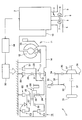
つぎにこの発明を具体例を図2に基づいて説明する。この発明で対象とする車両1にはエンジン2が搭載されている。このエンジン2は、燃料を燃焼させて動力を出力する動力装置であり、エンジン2としては内燃機関、例えば、ガソリンエンジンまたはディーゼルエンジンまたはLPGエンジンなどを用いることができる。この具体例では、エンジン2としてガソリンエンジンを用いているものとして説明する。エンジン2には燃焼室(図示せず)が設けられており、この燃焼室に空気を供給する吸気管3が設けられている。この吸気管3にはスロットルバルブ4が設けられている。スロットルバルブ4は空気の流通する断面積を制御する装置である。また、燃焼室に燃料を供給する燃料噴射装置(図示せず)、および燃料と空気との混合気に点火する点火装置(図示せず)が設けられている。また、燃焼室で燃料が燃焼されて生じた排気ガスが、燃焼室から大気中に排出される過程で通る排気管5が設けられている。
Next, a specific example of the present invention will be described with reference to FIG. An
さらに、エンジン2の燃焼室に吸入される空気を圧縮する過給機6が設けられている。この過給機6は、排気タービン式の過給機である。具体的に説明すると過給機6は、排気管5内に配置されたタービン7と、タービン7に回転軸8を介して接続され、かつ、前記吸気管3内に配置されたコンプレッサ9とを有している。コンプレッサ9は、吸気管3内における空気の吸入方向で、スロットルバルブ4よりも上流に配置されている。このように構成された過給機6は、排気管5を通る排気ガスの流動エネルギによりタービン7が回転し、そのタービン7のトルクがコンプレッサ9に伝達されてコンプレッサ9が回転し、吸気管3内の空気を圧縮する。
Further, a supercharger 6 is provided for compressing air taken into the combustion chamber of the
このエンジン2においては、燃料の燃焼によって発生した熱エネルギが、クランクシャフト10の回転運動に変換される構成であり、そのクランクシャフト10と動力伝達可能に流体伝動装置11が設けられている。この流体伝動装置11は流体の運動エネルギにより動力伝達をおこなうことのできる装置である。流体伝動装置は、ポンプインペラ12およびタービンランナ13を有しており、ポンプインペラ12がクランクシャフト10に動力伝達可能に、具体的には一体的に回転するように連結されている。また、タービンランナ13にはインプットシャフト14が動力伝達可能に接続されている。さらに、インプットシャフト14から車輪15に至る動力伝達経路には変速機16が設けられている。この変速機16は、複数組の遊星歯車機構を有している。具体的には、第1の遊星歯車機構17および第2の遊星歯車機構18を有している。第1の遊星歯車機構17は、副変速部を構成するものであり、シングルピニオン型の遊星歯車機構により構成されている。この第1の遊星歯車機構17は、相互に同軸上に配置されたサンギヤ19およびリングギヤ20と、サンギヤ19およびリングギヤ20に噛合されたピニオンギヤ21を、自転かつ公転可能に保持するキャリヤ22とを有している。そして、サンギヤ19がインプットシャフト14と一体回転するように連結されている。このように、第1の遊星歯車機構17は、サンギヤ19およびリングギヤ20およびキャリヤ22で合計3個の回転要素を有している。
The
また、前記インプットシャフト14と同軸上にインターミディエイトシャフト23が設けられている。インプットシャフト14およびインターミディエイトシャフト23は、一体回転するように連結されている。そのインターミディエイトシャフト23の外周側に第2の遊星歯車機構18が配置されている。この第2の遊星歯車機構18は、主変速部を構成するものであり、ラビニョ型の遊星歯車機構により構成されている。第2の遊星歯車機構18は、同軸上に配置された第1サンギヤ24およびリングギヤ25と、第1サンギヤ24に噛合されたショートピニオンギヤ26と、このショートピニオンギヤ26およびリングギヤ25に噛合されたロングピニオンギヤ27と、ショートピニオンギヤ26およびロングピニオンギヤ27をそれぞれ自転可能に、かつ、一体的に公転するように保持するキャリヤ28と、ロングピニオンギヤ27に噛合された第2サンギヤ29とを有している。第1サンギヤ24と第2サンギヤ29とは相対回転可能に、かつ同軸上に配置されている。さらに第1サンギヤ24の歯数は第2サンギヤ29の歯数よりも少なく構成されている。そして、第1サンギヤ24とキャリヤ22とが一体回転するように連結されている。このように、第2の遊星歯車機構18は、第1サンギヤ24および第2サンギヤ29およびリングギヤ25およびキャリヤ28からなる4つの回転要素を有している。
An intermediate shaft 23 is provided coaxially with the
つぎに、第1の遊星歯車機構17および第2の遊星歯車機構18の回転要素同士を接続・解放するクラッチ、および各回転要素を選択的に停止(固定)するブレーキについて説明する。まず、前記第2サンギヤ29とインターミディエイトシャフト23とを選択的に接続・解放する第1クラッチC1が設けられている。また、リングギヤ25とインターミディエイトシャフト23とを選択的に接続・解放する第2クラッチC2が設けられている。さらに、キャリヤ22および第1サンギヤ24の両方を停止させる第1ブレーキB1が設けられている。また、リングギヤ25を停止させる第2ブレーキB2が設けられている。さらに、リングギヤ20を停止させる第3ブレーキB3が設けられている。さらにまた、リングギヤ25が正方向に回転する場合は解放される一方、リングギヤ25を逆方向させる向きのトルクが生じた場合に係合されて、そのリングギヤ25を停止させる一方向クラッチF1が設けられている。なお、正方向とは、エンジン2のクランクシャフト10の回転方向と同じ回転方向を意味する。この具体例においては、各クラッチおよびブレーキなどの摩擦係合装置が、油圧により係合・解放が制御される油圧制御式の摩擦係合装置を用いられている場合を例として説明する。これらの摩擦係合装置の係合・解放を制御するために油圧制御装置30が設けられている。この油圧制御装置30は、油圧回路、切替バルブ、圧力制御弁、流量制御弁などを備えた公知のものである。そして、各摩擦係合装置毎に設けられた油圧室の油圧を制御することにより、各摩擦係合装置の係合・解放を制御することができる。より具体的には、摩擦係合装置を係合または解放する際に、油圧室(図示せず)の油圧を制御することにより、摩擦係合装置のトルク容量の変化率を制御することが可能である。
Next, a clutch for connecting and releasing the rotating elements of the first
つぎに、前記キャリヤ28から車輪15に至る動力伝達経路の構成を説明する。前記キャリヤ28はインターミディエイトシャフト23の外周に配置されており、キャリヤ28とインターミディエイトシャフト23とが相対回転可能である。このキャリヤ28にはカウンタドライブギヤ31が形成されている。また、インターミディエイトシャフト23は軸線を中心として回転可能に支持されており、そのインターミディエイトシャフト23の軸線と平行な軸線を中心として回転可能なカウンタシャフト32が設けられている。カウンタシャフト32にはカウンタドリブンギヤ33が形成されており、カウンタドライブギヤ31とカウンタドリブンギヤ33とが噛合されている。また、カウンタシャフト32にはドライブピニオンギヤ34が形成されている。さらに、デフケース35が設けられており、デフケース35の外周にはリングギヤ36が形成されている。このリングギヤ36とドライブピニオンギヤ34とが噛合されている。このリングギヤ36とドライブピニオンギヤ34とにより、終減速機が構成されている。また、デフケース35の内部にはピニオンギヤ(図示せず)およびサイドギヤ(図示せず)が設けられており、そのサイドギヤにはドライブシャフト37が接続されている。そのドライブシャフト37に車輪15が動力伝達可能に接続されている。
Next, the configuration of the power transmission path from the
さらに、車両1に搭載されたシステムを制御する制御系統について説明する。車両1に搭載されたシステムを制御するコントローラとして電子制御装置38が設けられており、その電子制御装置38には、エンジン2の始動要求、アクセルペダルの踏み込み状態を表すアクセル開度、ブレーキペダルの踏み込み状態、シフトポジション、車速、エンジン回転数、吸気管3内における過給圧、タービン7の回転数などを検知するセンサおよびスイッチの検知信号が入力される。この電子制御装置38は、エンジン出力を制御するデータ、および変速機16の変速段を制御するデータが記憶されている。そして、電子制御装置38に入力される信号、および電子制御装置38に記憶されているデータに基づいて、エンジン回転数およびエンジントルクを制御する信号、油圧制御装置30を制御する信号が出力される。
Furthermore, a control system for controlling a system mounted on the vehicle 1 will be described. An
例えば、エンジン2を始動する要求がある場合は、燃焼室に燃料が供給されるとともに、吸気管3を経由して燃焼室に空気が供給される。燃料および空気の混合気に点火されて燃焼し、その熱エネルギがクランクシャフト10の運動エネルギに変換される。燃料の燃焼により発生した排気ガスは、燃焼室から排気管5に排出され、ついで大気中に放出される。上記の作用中、排気ガスの流動エネルギでタービン7が回転されて、そのトルクによりコンプレッサ9が駆動されて、吸気管3を吸入される空気を圧縮して燃焼室に供給できる。したがって、燃焼室に供給される空気量を増加できる。また、過給機6は排気ガスの運動エネルギにより駆動されるため、排気ガス量が増加すると、吸気管3内の過給圧が相対的に高くなる。そして、クランクシャフト10のトルクは流体伝動装置11を経由してインプットシャフト14に伝達される。
For example, when there is a request to start the
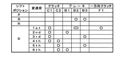
一方、車両1の室内に設けられたシフトポジション選択装置(図示せず)を操作すると、パーキング(P)ポジション、リバース(R)ポジション、ニュートラル(N)ポジション、ドライブ(D)ポジションを選択可能である。各シフトポジションの切替により、前記変速機16の制御がおこなわれる。各シフトポジションに対応する前記クラッチおよびブレーキの作動状態を、図3に基づいて説明する。この図3において、「○」印は、クラッチまたはブレーキが係合されることを意味し、「(○)」印は、エンジンブレーキ時にブレーキが係合されることを意味する。さらに、図3の空欄は、クラッチまたはブレーキが解放されることを意味する。そして、パーキングポジションが選択されている場合、またはニュートラルポジションが選択されている場合は、ブレーキおよびクラッチが全て解放されるため、インプットシャフト14に入力されたトルクがキャリヤ28に伝達されることはない。
On the other hand, when a shift position selection device (not shown) provided in the vehicle 1 is operated, a parking (P) position, a reverse (R) position, a neutral (N) position, and a drive (D) position can be selected. is there. The
これに対して、ドライブポジションまたはリバースポジションが選択された場合は、エンジントルクが車輪15に伝達される。まず、ドライブポジションについて説明する。前記電子制御装置38には変速機16の変速段を制御するために変速マップが記憶されており、ドライブポジションでは、その変速マップに基づいて、変速機の変速段が制御される。この変速マップは、車速およびアクセル開度をパラメータとして、各変速段を選択する領域を定めたものである。具体的には、変速機の変速段として第1速(1st)、第2速(2nd)、第3速(3rd)、第4速(4th)、第5速(5th)、第6速(6th)の変速段を選択的に切替可能である。
On the other hand, when the drive position or the reverse position is selected, the engine torque is transmitted to the
まず、第1速が選択された場合は、クラッチC1が係合される。ここで、エンジントルクがインプットシャフト14に伝達されると、サンギヤ19および第2サンギヤ29が正方向に一体回転するとともに、一方向クラッチF1が係合されて、リングギヤ25が停止する。つまり、第2の遊星歯車機構18において、第2サンギヤ29にトルクが入力されて、リングギヤ26が反力要素となり、キャリヤ28を正方向に回転させる向きのトルクが生じる。また、第1速が選択された場合、インプットシャフト14の回転数よりもキャリヤ28の回転数の方が低くなる。すなわちインプットシャフト14の回転数をキャリヤ28の回転数で除算して求められる変速機16の変速比は、「1」よりも大きい減速状態となる。このようにして、カウンタドリブンギヤ31に伝達されたトルクは、カウンタシャフト32およびドライブシャフト37を経由して車輪15に伝達されて駆動力が発生する。なお、第1速が選択されて車両1が走行中に、アクセルペダルが戻されて車両1が惰力走行する場合は、前記ブレーキB2が係合されてリングギヤ25が正方向に回転することが防止される。このため、車両1の惰力走行する運動エネルギが、キャリヤ28に伝達されると、リングギヤ25が反力要素となりエンジンブレーキ力が発生する。
First, when the first speed is selected, the clutch C1 is engaged. Here, when the engine torque is transmitted to the
つぎに、第2速が選択された場合を説明する。第2速が選択された場合は、第1ブレーキB1が係合されるため、キャリヤ22および第1サンギヤ24が共に停止される。そして、エンジントルクがインターミディエイトシャフト23を経由して第2サンギヤ29に伝達されると、第1サンギヤ24が反力要素となり、キャリヤ28を正方向に回転させる向きのトルクが発生する。また、第2速が選択された場合、インプットシャフト14の回転数よりもキャリヤ28の回転数の方が低くなる。すなわち、変速機16の変速比は、「1」よりも大きい減速状態となる。なお、第2速が選択された場合の変速比は、第1速が選択された場合の変速比よりも小さい。
Next, a case where the second speed is selected will be described. When the second speed is selected, since the first brake B1 is engaged, both the
つぎに、第3速が選択された場合を説明する。第3速が選択された場合は、第1ブレーキB3が係合されてリングギヤ20が停止する。そして、エンジントルクがサンギヤ19に入力されると、第1の遊星歯車機構17ではリングギヤ20が反力要素となり、サンギヤ19およびキャリヤ22が正方向に回転する。また、第2の遊星歯車機構18では、エンジントルクが第2サンギヤ29に伝達されると、キャリヤ22と一体回転する第1サンギヤ24がキャリヤ22が反力要素となり、キャリヤ28を正方向に回転させる向きのトルクが生じる。第3速が選択された場合、インプットシャフト14の回転数よりもキャリヤ28の回転数の方が低くなる。すなわち、変速機16の変速比は、「1」よりも大きい減速状態となる。なお、第3速が選択された場合の変速比は、第2速が選択された場合の変速比よりも小さい。
Next, a case where the third speed is selected will be described. When the third speed is selected, the first brake B3 is engaged and the
つぎに、第4速が選択された場合は、第1クラッチC1および第2クラッチC2が共に係合されるため、エンジントルクがインターミディエイトシャフト23に伝達されると、第2の遊星歯車機構18の回転要素が全て正方向に一体回転する。つまり、インプットシャフト14の回転数とキャリヤ28の回転数とが一致し、変速機16の変速比が「1」となる。
Next, when the fourth speed is selected, both the first clutch C1 and the second clutch C2 are engaged, so that when the engine torque is transmitted to the intermediate shaft 23, the second
つぎに、第5速が選択された場合を説明する。第5速が選択された場合は、第3ブレーキB3が係合されてリングギヤ20が固定され、反力要素となる。また、第2クラッチC2が係合されてサンギヤ19とリングギヤ25とが一体回転するように接続される。このため、エンジントルクがインターミディエイトシャフト23を経由してリングギヤ25に伝達されると、正回転する第1サンギヤ24が反力要素となり、キャリヤ28からトルクが出力される。また、第5速が選択された場合、インプットシャフト14の回転数よりもキャリヤ28の回転数の方が高くなる。すなわち、変速機16の変速比は、「1」よりも小さい増速状態(オーバードライブ状態)となる。
Next, a case where the fifth speed is selected will be described. When the fifth speed is selected, the third brake B3 is engaged and the
つぎに、第6速が選択された場合を説明する。第6速が選択された場合は、第1ブレーキB1が係合されて、キャリヤ22および第1サンギヤ24が共に停止される。また、第2クラッチC2が係合されてサンギヤ19とリングギヤ25とが一体回転するように接続される。このため、第1の遊星歯車機構17ではキャリヤ22が反力要素となる。また、エンジントルクがインターミディエイトシャフト23を経由してリングギヤ25に伝達されると、第1サンギヤ24が反力要素となり、キャリヤ28を正方向に回転させる向きのトルクが生じる。また、インプットシャフト14の回転数よりもキャリヤ28の回転数の方が高くなる。すなわち、変速機16の変速比は、「1」よりも小さい増速状態となる。なお、第6速では、第1サンギヤ24が停止しているため、第5速の変速比よりも第6速の変速比の方が小さい。このように、変速機16は、変速比を段階的に変更することの可能な有段変速機である。
Next, a case where the sixth speed is selected will be described. When the sixth speed is selected, the first brake B1 is engaged, and both the
また、ドライブポジションが選択されている場合、第1速と第2速との間で変速をおこなう場合、第1ブレーキB1および一方向クラッチF1の係合・解放が切り替えられて変速が実行される。第2速と第3速との間で変速をおこなう場合、第1ブレーキB1および第3ブレーキB3の係合・解放が切り替えられて変速が実行される。また、第3速と第4速との間で変速をおこなう場合、第2クラッチC2および第3ブレーキB3の係合・解放が切り替えられて変速が実行される。また、第4速と第5速との間で変速をおこなう場合、第1クラッチC1および第3ブレーキB3の係合・解放が切り替えられて変速が実行される。また、第5速と第6速との間で変速をおこなう場合、第1ブレーキB1および第3ブレーキB3の係合・解放が切り替えられて変速が実行される。このように、複数のクラッチおよびブレーキの係合・解放を切り替えて実行される変速が、クラッチ・ツウ・クラッチ変速である。このクラッチ・ツウ・クラッチ変速は、変速比を大きくする変速であるダウンシフト、および、変速比を小さくする変速であるアップシフトの両方でおこなわれる。 In addition, when the drive position is selected, when shifting between the first speed and the second speed, engagement / release of the first brake B1 and the one-way clutch F1 is switched to execute the shifting. . When shifting between the second speed and the third speed, the engagement and release of the first brake B1 and the third brake B3 are switched to execute the shifting. When shifting between the third speed and the fourth speed, the engagement and release of the second clutch C2 and the third brake B3 are switched to execute the shifting. When shifting between the fourth speed and the fifth speed, the engagement and release of the first clutch C1 and the third brake B3 are switched to execute the shifting. In addition, when shifting between the fifth speed and the sixth speed, engagement / release of the first brake B1 and the third brake B3 is switched to execute the shifting. In this way, a shift that is executed by switching engagement / release of a plurality of clutches and brakes is a clutch-to-clutch shift. This clutch-to-clutch shift is performed by both a downshift that is a shift that increases the gear ratio and an upshift that is a shift that decreases the gear ratio.
また、変速機16でクラッチ・ツウ・クラッチ変速をおこなう場合、変速後の変速段を設定する摩擦係合装置を係合する際に、その摩擦係合装置のトルク容量が増加して、変速機16から出力されるトルクが急激に増加してショックが生じることを防止するために、変速機16でクラッチ・ツウ・クラッチ変速をおこなう場合は、エンジントルクを低下させる制御、つまり、トルクダウン制御をおこなうこともできる。
Further, when performing clutch-to-clutch shift with the
さらにリバースポジションが選択された場合は、第2ブレーキB2および第3ブレーキB3が係合される。このため、エンジントルクがサンギヤ19に伝達されると、第1の遊星歯車機構17ではリングギヤ20が反力要素となり、キャリヤ22が正方向に回転する。すると、第2の遊星歯車機構18の第1サンギヤ24がキャリヤ22と共に正方向に一体回転し、リングギヤ25が反力要素となり、キャリヤ28が逆方向に回転する。
Further, when the reverse position is selected, the second brake B2 and the third brake B3 are engaged. For this reason, when the engine torque is transmitted to the
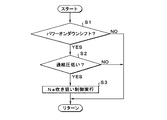
つぎに、ドライブポジションが選択され、かつ、変速機18で変速段を変更する制御例を、図1のフローチャートに基づいて説明する。まず、パワーオンでダウンシフトをおこなうか否かが判断される(ステップS1)。ここで、パワーオンとはアクセルペダルが踏み込まれていることを意味する。つまり、アクセルペダルが踏み込まれて、変速機16でクラッチ・ツウ・クラッチ変速となるダウンシフトがおこなわれるか否かを判断している。このステップS1で否定的に判断された場合は、スタートに戻る。これに対して、ステップS1で肯定的に判断された場合は、運転者が車両1の加速を意図していることになるので、エンジン2に対する燃料の供給量を増加してエンジン出力を相対的に高める必要がある。そこで、ステップS1で肯定的に判断された場合は、吸気管3内の過給圧が所定圧よりも低いか否かが判断される(ステップS2)。このステップS2では、エンジン出力を相対的に高めるにあたり、エンジン出力の制御応答性を確保することができるか否かを、過給圧を用いて判断している。このステップS2の判断に用いる所定圧は、車速、アクセル開度、変速機16の変速段などの条件に基づいて、実験またはシミュレーションをおこなって求めた値を、電子制御装置38に記憶してある。なお、吸気管3内の圧力は、圧力センサにより直接検知してもよいし、タービン7の回転数から間接的に求めることもできる。
Next, an example of control in which the drive position is selected and the gear position is changed by the
さらに、ステップS2は、エンジン出力の制御の応答性を判断するステップであるから、エンジントルクの変化率、あるいはアクセル開度から、エンジン出力の制御の応答性を判断することも可能である。このステップS2で否定的に判断されるということは、エンジン出力の増加を制御の応答性が、予め定めた基準値を満たしていることになるため、スタートに戻る。これに対して、ステップS2で肯定的に判断された場合は、変速機16でダウンシフト制御を実行する途中で、エンジン回転数(Ne)を上昇させる(吹き上げさせる)ことを狙いとする制御を実行し(ステップS3)、スタートに戻る。このステップS3の技術的意味は、エンジン回転数を上昇させて排気管5に排出される排気ガスの量を増加し、タービン7の回転数を相対的に上昇させて、吸気管3内の過給圧を相対的に高めることにある。
Furthermore, since step S2 is a step for determining the response of the engine output control, it is also possible to determine the response of the engine output control from the rate of change of the engine torque or the accelerator opening. The negative determination in step S2 returns to the start because the responsiveness of the control for increasing the engine output satisfies a predetermined reference value. On the other hand, if the determination in step S2 is affirmative, the control aiming to increase (blow up) the engine speed (Ne) during the downshift control in the
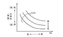
ここで、エンジン回転数(Ne)と過給圧の制御応答性との関係を、図4のマップにより例示する。この図4では、横軸にエンジン回転数が示され、縦軸に応答性が示されている。この応答性は、過給圧が一定圧上昇するのに要する所要時間を意味している。この図4は、エンジン回転数が相対的に高くなると、所要時間が短くなること、つまり、応答性が高くなることを示している。そしてステップS3では、ダウンシフト後の変速段で係合される摩擦係合装置のトルク容量を制御することにより、ダウンシフト中におけるエンジン回転数の上昇を促進する。 Here, the relationship between the engine speed (Ne) and the control response of the supercharging pressure is illustrated by the map of FIG. In FIG. 4, the horizontal axis indicates the engine speed, and the vertical axis indicates responsiveness. This responsiveness means the time required for the boost pressure to increase by a certain pressure. FIG. 4 shows that when the engine speed is relatively high, the required time is shortened, that is, the responsiveness is enhanced. In step S3, an increase in engine speed during the downshift is promoted by controlling the torque capacity of the friction engagement device engaged at the shift stage after the downshift.
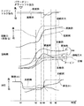
このステップS3の処理を、図6のタイムチャートにより具体的に説明する。ここでは、変速機16で第3速から第2速にダウンシフトする場合を例として説明する。まず、時刻t1以前には第3ブレーキB3が係合されて第3速が設定されている。つまり、第3ブレーキB3を係合させる油圧室の油圧が、相対的に高圧に制御されている。また、エンジントルクは略一定に制御されている。そして、時刻t1でパワーオンダウンシフトをおこなう変速信号が出力されて、第3ブレーキB3に作用する油圧が、実線で示すように低下する。つまり、第3ブレーキB3のトルク容量が低下する。すると、エンジン2における負荷(引きずりトルク)が低下して、エンジン回転数が実線で示すように上昇を開始する。なお、時刻t1以後に、第1ブレーキB1に作用する油圧が、図に示すように上昇される。このように、第3ブレーキB3のトルク容量が低下されることにより、エンジン回転数の上昇が促進されて、排気ガス量が増加し、タービン7の回転数が実線で示すように上昇する。このため、タービン7の実回転数は、ダウンシフト後における目標回転数(一点鎖線で示す)よりも高くなる。
The processing in step S3 will be specifically described with reference to the time chart of FIG. Here, a case where the
すると、実エンジン回転数は、第2速の変速比に対応する目標エンジン回転数よりも高くなり、目標エンジン回転数と実エンジン回転数との差が所定値となった時刻t4において、エンジントルクをダウンさせる制御が開始される。この時刻t4以降、駆動力の増加率が、時刻t4以前よりも小さく(少なく)なる。駆動力は、車両1において前後方向の加速度(G)を生じさせる。すると、実エンジン回転数が低下し、かつ、タービン7の回転数も低下する。そして、時刻t5でエンジントルクが時刻t4以前の値に戻され、時刻t5で実エンジン回転数が目標エンジン回転数と一致し、第3速から第2速へのダウンシフトが終了する。また、時刻t6以降は、タービン7の実回転数が目標回転数に一致し、かつ、第1ブレーキB1に作用する油圧が、第2速における目標油圧に制御されている。なお、時刻t4から時刻t5の間、エンジントルクをダウンさせる制御がおこなわれるため、「第1ブレーキB1のトルク容量が高められることにともなう変速機16の出力トルクの変動」を抑制できる。このエンジントルクをダウンさせる制御も、図1のステップS3でおこなわれる。
Then, the actual engine speed becomes higher than the target engine speed corresponding to the gear ratio of the second speed, and at time t4 when the difference between the target engine speed and the actual engine speed becomes a predetermined value, the engine torque Control to bring down is started. After this time t4, the increase rate of the driving force is smaller (less) than before time t4. The driving force causes the longitudinal acceleration (G) in the vehicle 1. As a result, the actual engine speed decreases and the rotational speed of the
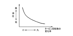
このように、図1のフローチャートでは、吸気管3内の過給圧が相対的に低いほど、タービン7の実回転数および実エンジン回転数の上昇率が増加するように、ダウンシフト制御中に解放される第3ブレーキB3の油圧の低下率を大きくする。具体的には、「ダウンシフト途中で用いる目標回転数」を、「ダウンシフト後の変速段における目標回転数」よりも高く設定し、タービン7の実回転数を「ダウンシフト途中で用いる目標回転数」に近づけるように、フィードバック制御をおこなう。この制御に用いるマップを、図5に基づいて説明する。図5では、横軸にタービン7の回転数の変化率が示され、縦軸に摩擦係合装置に作用する油圧が示されている。ここで、摩擦係合装置に作用する油圧が低下するほど、タービン7の回転数の変化率が、相対的に大きくなる特性を有している。このようにして、排気管5に排出される排気ガス量が増加して、吸気管3の過給圧が相対的に高められる。
As described above, in the flowchart of FIG. 1, during the downshift control, the increase rate of the actual rotational speed of the
ここで、ダウンシフト中における比較例の制御を、図6で説明する。時刻t1から油圧が破線で示すように低下される。この比較例の油圧は、実施例の油圧よりも高く、比較例における引きずりトルクは実施例の引きずりトルクよりも大きい。このため、比較例におけるタービンの回転数の上昇率は、実施例におけるタービンの回転数の上昇率よりも低くなる。また、比較例におけるエンジン回転数の上昇率は、実施例におけるエンジン回転数の上昇率よりも低くなる。また、比較例は、時刻t3からエンジントルクをダウンさせる制御を実行しており、比較例におけるエンジン回転数の上昇率は、実施例におけるエンジン回転数の上昇率よりも、一層少なくなっている。また、時刻t3以降は、駆動力の上昇率が、時刻t3以前よりも小さくなっている。さらに、時刻t4から時刻t5に至る過程で、ダウンシフト後の変速段で係合される摩擦係合装置の油圧が、ダウンシフト後の目標油圧まで上昇されている。すなわち、実施例における第1ブレーキB1の油圧の上昇率は、比較例の摩擦係合装置の油圧上昇率よりも小さい(低い)。なお、図6のタイムチャートには、過給圧が元々所定圧以上であり、ステップS2で否定的に判断される場合の経時変化も示されている。例えば、タービン回転数は破線で示すように、時刻t3まで急激に上昇し、時刻t3以降は緩やかに上昇している。時刻t3ないし時刻t5の間におけるタービン回転数は、実施例のタービン回転数よりも低い。また、過給圧が大である場合の駆動力も破線で示されている。過給圧が大である場合の駆動力は、実施例の駆動力よりも常時大である。
Here, the control of the comparative example during the downshift will be described with reference to FIG. From time t1, the hydraulic pressure is decreased as indicated by a broken line. The hydraulic pressure of this comparative example is higher than the hydraulic pressure of the example, and the drag torque in the comparative example is larger than the drag torque of the example. For this reason, the increase rate of the rotation speed of the turbine in the comparative example is lower than the increase rate of the rotation speed of the turbine in the embodiment. Further, the increase rate of the engine speed in the comparative example is lower than the increase rate of the engine speed in the embodiment. In the comparative example, control for reducing the engine torque is performed from time t3, and the rate of increase in engine speed in the comparative example is much smaller than the rate of increase in engine speed in the example. Further, after time t3, the increase rate of the driving force is smaller than before time t3 . Et al is in process from time t4 to time t5, the oil pressure of the frictional engagement device to be engaged in speed after the downshift has been raised to the target hydraulic pressure after the downshift. That is, the increase rate of the hydraulic pressure of the first brake B1 in the embodiment is smaller (lower) than the increase rate of the hydraulic pressure of the friction engagement device of the comparative example. Note that the time chart of FIG. 6 also shows changes over time when the supercharging pressure is originally equal to or higher than the predetermined pressure and is negatively determined in step S2. For example, as indicated by a broken line, the turbine rotation speed increases rapidly until time t3, and gradually increases after time t3. The turbine rotational speed between time t3 and time t5 is lower than the turbine rotational speed of the embodiment. The driving force when the supercharging pressure is large is also indicated by a broken line. When the supercharging pressure is large, the driving force is always larger than the driving force of the embodiment.
また、この実施例では、ステップS3において学習制御をおこなうこともできる。具体的には、タービン7の実回転数の変化率と過給圧との関係を学習する学習制御である。この学習制御をおこなうと、ある過給圧において、タービン7の回転数の変化率をどの程度に設定すれば、過給圧の増加応答性を確保することができるかを判断することができ、その判断結果を、以後、ステップS3でエンジン回転数を上昇させる場合の制御に用いることができる。すると、摩擦係合装置の油圧を制御して、実エンジン回転数を目標エンジン回転数に近づけるフィードバック制御をおこなう場合に、そのフィードバック制御の精度を向上させることができる。
In this embodiment, learning control can also be performed in step S3. Specifically, the learning control is to learn the relationship between the change rate of the actual rotational speed of the
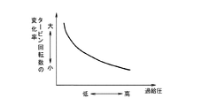
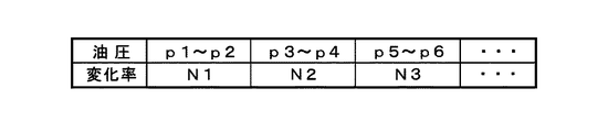
さらに、タービン7の実回転数の変化率と、過給圧との関係を学習する例を、図7のマップにより説明する。このマップでは、横軸に過給圧が示され、縦軸にタービン7の実回転数の変化率が示されている。このマップでは、過給圧が相対的に高くなるほど、タービン7の実回転数の変化率が相対的に小さくなることが、リニアに学習されている。また、タービン7の実回転数の変化率と過給圧との関係を、段階的に学習することも可能である。これを、図8に基づいて説明する。この図8では、過給圧が複数段階の圧力範囲p1〜p2、p3〜p4、p5〜p6・・・に区分されている。ここで、p1<p2<p3<p4<p5<p6の関係にある。また、区分された圧力範囲毎に、タービン7の実回転数の変化率N1、N2、N3・・・が学習されている。ここで、N1<N2<N3の関係にある。
Furthermore, an example of learning the relationship between the change rate of the actual rotational speed of the
なお、図1に示された制御例は、変速機16で第6速から第5速にダウンシフトする場合、第5速から第4速にダウンシフトする場合、第4速から第3速にダウンシフトする場合、第3速から第2速にダウンシフトする場合、第2速から第1速にダウンシフトする場合のいずれにおいても実行可能である。すなわち、ダウンシフト後の変速段で解放される摩擦係合装置のトルク容量の低下量、またはトルク容量の低下率を相対的に大きくすることにより、エンジン回転数およびタービン76の回転数の上昇率を相対的に増加することができる。
In the control example shown in FIG. 1, when the
ここで、上記の具体例に基づいて説明された構成と、この発明の構成との対応関係を説明すると、クラッチ・ツウ・クラッチ変速をおこなう場合に、変速後の変速段で解放されるクラッチやブレーキなどの摩擦係合装置が、この発明におけるトルク容量制御装置に相当する。より具体的には、変速前の変速段で係合されている摩擦係合装置が、この発明の「いずれかのトルク容量制御装置」に相当し、変速後の変速段で係合される摩擦係合装置が、この発明の「他のトルク容量制御装置」に相当する。また、図1に示された機能的手段と、この発明の構成との対応関係を説明すると、ステップS2が、この発明における空気圧検知手段に相当し、ステップS3が、この発明の制御手段およびエンジントルク制御手段および学習制御手段に相当する。なお、上記の実施例では、変速機の変速段を制御する摩擦係合装置のトルク容量を制御して、過給機のタービンの回転数の上昇率およびエンジン回転数の上昇率を制御しているが、エンジンから変速機に至る経路に、流体伝動装置と並列に、トルク容量制御装置としてロックアップクラッチが設けられている場合は、変速機の変速時に、係合されているロックアップクラッチのトルク容量を低下させることにより、上記の実施例と同様の作用効果を得ることもできる。 Here, the correspondence relationship between the configuration described based on the above specific example and the configuration of the present invention will be described. When performing clutch-to-clutch shift, the clutch released at the shift stage after the shift, A friction engagement device such as a brake corresponds to the torque capacity control device of the present invention. More specifically, the friction engagement device engaged in the gear stage before the shift corresponds to “any torque capacity control device” of the present invention, and the friction engaged in the gear stage after the shift. The engagement device corresponds to “another torque capacity control device” of the present invention. Further, the correspondence between the functional means shown in FIG. 1 and the configuration of the present invention will be described. Step S2 corresponds to the air pressure detecting means in the present invention, and step S3 corresponds to the control means and engine of the present invention. It corresponds to torque control means and learning control means. In the above-described embodiment, the torque capacity of the friction engagement device that controls the gear position of the transmission is controlled, and the rate of increase in the rotational speed of the turbine and the rate of increase in the engine speed of the turbocharger are controlled. However, if a lock-up clutch is provided as a torque capacity control device in parallel with the fluid transmission device in the path from the engine to the transmission, the lock-up clutch that is engaged is By reducing the torque capacity, it is possible to obtain the same effect as the above-described embodiment.
1…車両、 2…エンジン、 6…過給機、 16…変速機、 38…電子制御装置、 B1…第1ブレーキ、 B3…第3ブレーキ、 C1…第1クラッチ、 C2…第2クラッチ、 F1…一方向クラッチ。 DESCRIPTION OF SYMBOLS 1 ... Vehicle, 2 ... Engine, 6 ... Supercharger, 16 ... Transmission, 38 ... Electronic control unit B1 ... 1st brake, B3 ... 3rd brake, C1 ... 1st clutch, C2 ... 2nd clutch, F1 ... one-way clutch.
Claims (4)
前記過給機により圧縮された空気の圧力を検知する空気圧検知手段と、
前記過給機により圧縮された空気の圧力が低いほど、エンジン回転数の上昇率が大きくなり、前記過給機により圧縮される空気の圧力が上昇するように、前記トルク容量制御装置のトルク容量を低く設定する制御手段と
を有していることを特徴とする車両の制御装置。
An engine that generates power by mixing and combusting the sucked air and fuel, a supercharger that is driven by the engine and compresses the air sucked into the engine, and output from the engine that is disposed in the transmission path of the power, and, in the control device for the vehicle with a torque capacity control device which can change the capacity of the torque is reached transfer by controlling the engaging force,
Air pressure detecting means for detecting the pressure of the air compressed by the supercharger;
The pressure of the air compressed by the supercharger low Ihodo, increase rate of the engine speed is greatly such that said pressure of the air compressed by the supercharger is increased, the torque capacity control device control device for a vehicle, characterized in that a control unit for a low Ku sets the torque capacity.
前記他のトルク容量制御装置のトルク容量を高めることにより生じる前記変速機の出力トルクの変動を抑制するために、エンジントルクを低下させる制御をおこなうにあたり、実際のエンジン回転数が、前記変速比を大きくする制御をおこなう際における目標エンジン回転数に到達した後に、前記エンジントルクを低下させる制御をおこなうエンジントルク制御手段を有していることを特徴とする請求項2に記載の車両の制御装置。 The transmission has a plurality of torque capacity control devices, and controls to increase the gear ratio by reducing the torque capacity of one of the torque capacity control devices and increasing the torque capacity of another torque capacity control device. And
In order to suppress fluctuations in the output torque of the transmission caused by increasing the torque capacity of the other torque capacity control device, in performing control to reduce the engine torque, the actual engine speed is set to the speed ratio. 3. The vehicle control device according to claim 2, further comprising engine torque control means for performing control to decrease the engine torque after reaching a target engine speed when performing control to increase.
前記タービンの回転数の変化率と前記コンプレッサにより圧縮された空気の圧力との関係を学習する学習制御手段を備えていることを特徴とする請求項1ないし3のいずれかに記載の車両の制御装置。 The supercharger has a turbine driven by kinetic energy of exhaust gas generated by burning fuel, and a compressor driven by torque of the turbine to compress air.
The vehicle control according to any one of claims 1 to 3, further comprising learning control means for learning a relationship between a rate of change in the rotational speed of the turbine and a pressure of air compressed by the compressor. apparatus.
Priority Applications (1)
| Application Number | Priority Date | Filing Date | Title |
|---|---|---|---|
| JP2007329276A JP4816632B2 (en) | 2007-12-20 | 2007-12-20 | Vehicle control device |
Applications Claiming Priority (1)
| Application Number | Priority Date | Filing Date | Title |
|---|---|---|---|
| JP2007329276A JP4816632B2 (en) | 2007-12-20 | 2007-12-20 | Vehicle control device |
Publications (2)
| Publication Number | Publication Date |
|---|---|
| JP2009150322A JP2009150322A (en) | 2009-07-09 |
| JP4816632B2 true JP4816632B2 (en) | 2011-11-16 |
Family
ID=40919708
Family Applications (1)
| Application Number | Title | Priority Date | Filing Date |
|---|---|---|---|
| JP2007329276A Expired - Fee Related JP4816632B2 (en) | 2007-12-20 | 2007-12-20 | Vehicle control device |
Country Status (1)
| Country | Link |
|---|---|
| JP (1) | JP4816632B2 (en) |
Families Citing this family (2)
| Publication number | Priority date | Publication date | Assignee | Title |
|---|---|---|---|---|
| JP2014080943A (en) * | 2012-10-18 | 2014-05-08 | Toyota Motor Corp | Control device of vehicle |
| JP2021020522A (en) * | 2019-07-25 | 2021-02-18 | トヨタ自動車株式会社 | Control device of hybrid vehicle |
Family Cites Families (1)
| Publication number | Priority date | Publication date | Assignee | Title |
|---|---|---|---|---|
| JP4251025B2 (en) * | 2003-06-30 | 2009-04-08 | トヨタ自動車株式会社 | Vehicle control device |
-
2007
- 2007-12-20 JP JP2007329276A patent/JP4816632B2/en not_active Expired - Fee Related
Also Published As
| Publication number | Publication date |
|---|---|
| JP2009150322A (en) | 2009-07-09 |
Similar Documents
| Publication | Publication Date | Title |
|---|---|---|
| JP4155287B2 (en) | Shift control device for automatic transmission for vehicle | |
| US9371070B2 (en) | System to control the torque of an internal combustion engine during a gear change | |
| JP4228789B2 (en) | Vehicle control device | |
| EP2867507B1 (en) | Control system for a vehicle for controlling an internal combustion engine during transmission gear shifting | |
| JP4453714B2 (en) | Vehicle control device | |
| JP4745284B2 (en) | Shift shock reduction device for power train | |
| JP4639760B2 (en) | Shift control device for automatic transmission | |
| JP4200992B2 (en) | Shift control device for automatic transmission for vehicle | |
| US6749534B2 (en) | Apparatus for controlling vehicle drive system including drive power source and automatic transmission | |
| JP5472530B2 (en) | Transmission control device and transmission control method | |
| JP2009150457A (en) | Vehicle and control method thereof | |
| JP4816632B2 (en) | Vehicle control device | |
| JP2008144738A (en) | Control device for vehicle power output device | |
| JP2010209850A (en) | Supercharging control device | |
| US7121979B2 (en) | Powertrain for motor vehicle | |
| JP4923547B2 (en) | Shift control device for automatic transmission for vehicle | |
| JP4222309B2 (en) | Vehicle control device | |
| JP2018042407A (en) | Vehicle control device | |
| JP2010043584A (en) | Controller for vehicle | |
| JP6003615B2 (en) | Shift control device for automatic transmission for vehicle | |
| JP4797573B2 (en) | Shift control device for automatic transmission for vehicle | |
| JP2014201086A (en) | Vehicle control device | |
| JP5029394B2 (en) | Control device for automatic transmission, control method, program for causing computer to realize the method, and recording medium recording the program | |
| JP2004308587A (en) | Vehicle control device | |
| JP6927129B2 (en) | Power transmission device control device |
Legal Events
| Date | Code | Title | Description |
|---|---|---|---|
| A621 | Written request for application examination |
Free format text: JAPANESE INTERMEDIATE CODE: A621 Effective date: 20100125 |
|
| A977 | Report on retrieval |
Free format text: JAPANESE INTERMEDIATE CODE: A971007 Effective date: 20110427 |
|
| A131 | Notification of reasons for refusal |
Free format text: JAPANESE INTERMEDIATE CODE: A131 Effective date: 20110524 |
|
| A521 | Written amendment |
Free format text: JAPANESE INTERMEDIATE CODE: A523 Effective date: 20110616 |
|
| TRDD | Decision of grant or rejection written | ||
| A01 | Written decision to grant a patent or to grant a registration (utility model) |
Free format text: JAPANESE INTERMEDIATE CODE: A01 Effective date: 20110802 |
|
| A01 | Written decision to grant a patent or to grant a registration (utility model) |
Free format text: JAPANESE INTERMEDIATE CODE: A01 |
|
| A61 | First payment of annual fees (during grant procedure) |
Free format text: JAPANESE INTERMEDIATE CODE: A61 Effective date: 20110815 |
|
| FPAY | Renewal fee payment (event date is renewal date of database) |
Free format text: PAYMENT UNTIL: 20140909 Year of fee payment: 3 |
|
| R151 | Written notification of patent or utility model registration |
Ref document number: 4816632 Country of ref document: JP Free format text: JAPANESE INTERMEDIATE CODE: R151 |
|
| FPAY | Renewal fee payment (event date is renewal date of database) |
Free format text: PAYMENT UNTIL: 20140909 Year of fee payment: 3 |
|
| LAPS | Cancellation because of no payment of annual fees |