JP4814259B2 - Method for manufacturing gas distribution member for plasma processing apparatus and method for adjusting gas permeability of the member - Google Patents
Method for manufacturing gas distribution member for plasma processing apparatus and method for adjusting gas permeability of the member Download PDFInfo
- Publication number
- JP4814259B2 JP4814259B2 JP2007555173A JP2007555173A JP4814259B2 JP 4814259 B2 JP4814259 B2 JP 4814259B2 JP 2007555173 A JP2007555173 A JP 2007555173A JP 2007555173 A JP2007555173 A JP 2007555173A JP 4814259 B2 JP4814259 B2 JP 4814259B2
- Authority
- JP
- Japan
- Prior art keywords
- gas
- zone
- distribution member
- gas flow
- zones
- Prior art date
- Legal status (The legal status is an assumption and is not a legal conclusion. Google has not performed a legal analysis and makes no representation as to the accuracy of the status listed.)
- Expired - Fee Related
Links
- 238000009826 distribution Methods 0.000 title claims description 110
- 238000000034 method Methods 0.000 title claims description 74
- 238000012545 processing Methods 0.000 title claims description 48
- 230000035699 permeability Effects 0.000 title claims description 39
- 238000004519 manufacturing process Methods 0.000 title claims description 11
- 238000002347 injection Methods 0.000 claims description 67
- 239000007924 injection Substances 0.000 claims description 67
- 238000005259 measurement Methods 0.000 claims description 9
- 229910052710 silicon Inorganic materials 0.000 claims description 7
- 239000010703 silicon Substances 0.000 claims description 7
- HBMJWWWQQXIZIP-UHFFFAOYSA-N silicon carbide Chemical compound [Si+]#[C-] HBMJWWWQQXIZIP-UHFFFAOYSA-N 0.000 claims description 5
- 229910010271 silicon carbide Inorganic materials 0.000 claims description 5
- 238000002834 transmittance Methods 0.000 claims description 5
- 239000000758 substrate Substances 0.000 description 18
- 238000005553 drilling Methods 0.000 description 17
- 239000004065 semiconductor Substances 0.000 description 10
- 230000015572 biosynthetic process Effects 0.000 description 8
- XUIMIQQOPSSXEZ-UHFFFAOYSA-N Silicon Chemical compound [Si] XUIMIQQOPSSXEZ-UHFFFAOYSA-N 0.000 description 5
- 238000012937 correction Methods 0.000 description 3
- 229910052782 aluminium Inorganic materials 0.000 description 2
- XAGFODPZIPBFFR-UHFFFAOYSA-N aluminium Chemical compound [Al] XAGFODPZIPBFFR-UHFFFAOYSA-N 0.000 description 2
- 229910021417 amorphous silicon Inorganic materials 0.000 description 2
- 238000009530 blood pressure measurement Methods 0.000 description 2
- 238000005530 etching Methods 0.000 description 2
- 238000003754 machining Methods 0.000 description 2
- 239000000463 material Substances 0.000 description 2
- 229910021421 monocrystalline silicon Inorganic materials 0.000 description 2
- 229910021420 polycrystalline silicon Inorganic materials 0.000 description 2
- 229910000838 Al alloy Inorganic materials 0.000 description 1
- 230000002411 adverse Effects 0.000 description 1
- 230000000712 assembly Effects 0.000 description 1
- 238000000429 assembly Methods 0.000 description 1
- 230000005540 biological transmission Effects 0.000 description 1
- 238000004891 communication Methods 0.000 description 1
- 238000005260 corrosion Methods 0.000 description 1
- 230000007797 corrosion Effects 0.000 description 1
- 230000008878 coupling Effects 0.000 description 1
- 238000010168 coupling process Methods 0.000 description 1
- 238000005859 coupling reaction Methods 0.000 description 1
- 230000007423 decrease Effects 0.000 description 1
- 238000013461 design Methods 0.000 description 1
- 230000009977 dual effect Effects 0.000 description 1
- 230000000694 effects Effects 0.000 description 1
- 230000003628 erosive effect Effects 0.000 description 1
- 229910052751 metal Inorganic materials 0.000 description 1
- 239000002184 metal Substances 0.000 description 1
- 239000007769 metal material Substances 0.000 description 1
- 230000000149 penetrating effect Effects 0.000 description 1
- 229920005591 polysilicon Polymers 0.000 description 1
- 239000011148 porous material Substances 0.000 description 1
- 239000011253 protective coating Substances 0.000 description 1
- 230000001681 protective effect Effects 0.000 description 1
- 239000002002 slurry Substances 0.000 description 1
- 238000003786 synthesis reaction Methods 0.000 description 1
- 238000012360 testing method Methods 0.000 description 1
- 238000012546 transfer Methods 0.000 description 1
Images

Classifications
-
- C—CHEMISTRY; METALLURGY
- C23—COATING METALLIC MATERIAL; COATING MATERIAL WITH METALLIC MATERIAL; CHEMICAL SURFACE TREATMENT; DIFFUSION TREATMENT OF METALLIC MATERIAL; COATING BY VACUUM EVAPORATION, BY SPUTTERING, BY ION IMPLANTATION OR BY CHEMICAL VAPOUR DEPOSITION, IN GENERAL; INHIBITING CORROSION OF METALLIC MATERIAL OR INCRUSTATION IN GENERAL
- C23C—COATING METALLIC MATERIAL; COATING MATERIAL WITH METALLIC MATERIAL; SURFACE TREATMENT OF METALLIC MATERIAL BY DIFFUSION INTO THE SURFACE, BY CHEMICAL CONVERSION OR SUBSTITUTION; COATING BY VACUUM EVAPORATION, BY SPUTTERING, BY ION IMPLANTATION OR BY CHEMICAL VAPOUR DEPOSITION, IN GENERAL
- C23C16/00—Chemical coating by decomposition of gaseous compounds, without leaving reaction products of surface material in the coating, i.e. chemical vapour deposition [CVD] processes
- C23C16/44—Chemical coating by decomposition of gaseous compounds, without leaving reaction products of surface material in the coating, i.e. chemical vapour deposition [CVD] processes characterised by the method of coating
- C23C16/455—Chemical coating by decomposition of gaseous compounds, without leaving reaction products of surface material in the coating, i.e. chemical vapour deposition [CVD] processes characterised by the method of coating characterised by the method used for introducing gases into reaction chamber or for modifying gas flows in reaction chamber
- C23C16/45563—Gas nozzles
- C23C16/45565—Shower nozzles
-
- C—CHEMISTRY; METALLURGY
- C23—COATING METALLIC MATERIAL; COATING MATERIAL WITH METALLIC MATERIAL; CHEMICAL SURFACE TREATMENT; DIFFUSION TREATMENT OF METALLIC MATERIAL; COATING BY VACUUM EVAPORATION, BY SPUTTERING, BY ION IMPLANTATION OR BY CHEMICAL VAPOUR DEPOSITION, IN GENERAL; INHIBITING CORROSION OF METALLIC MATERIAL OR INCRUSTATION IN GENERAL
- C23C—COATING METALLIC MATERIAL; COATING MATERIAL WITH METALLIC MATERIAL; SURFACE TREATMENT OF METALLIC MATERIAL BY DIFFUSION INTO THE SURFACE, BY CHEMICAL CONVERSION OR SUBSTITUTION; COATING BY VACUUM EVAPORATION, BY SPUTTERING, BY ION IMPLANTATION OR BY CHEMICAL VAPOUR DEPOSITION, IN GENERAL
- C23C16/00—Chemical coating by decomposition of gaseous compounds, without leaving reaction products of surface material in the coating, i.e. chemical vapour deposition [CVD] processes
-
- C—CHEMISTRY; METALLURGY
- C23—COATING METALLIC MATERIAL; COATING MATERIAL WITH METALLIC MATERIAL; CHEMICAL SURFACE TREATMENT; DIFFUSION TREATMENT OF METALLIC MATERIAL; COATING BY VACUUM EVAPORATION, BY SPUTTERING, BY ION IMPLANTATION OR BY CHEMICAL VAPOUR DEPOSITION, IN GENERAL; INHIBITING CORROSION OF METALLIC MATERIAL OR INCRUSTATION IN GENERAL
- C23F—NON-MECHANICAL REMOVAL OF METALLIC MATERIAL FROM SURFACE; INHIBITING CORROSION OF METALLIC MATERIAL OR INCRUSTATION IN GENERAL; MULTI-STEP PROCESSES FOR SURFACE TREATMENT OF METALLIC MATERIAL INVOLVING AT LEAST ONE PROCESS PROVIDED FOR IN CLASS C23 AND AT LEAST ONE PROCESS COVERED BY SUBCLASS C21D OR C22F OR CLASS C25
- C23F1/00—Etching metallic material by chemical means
-
- H—ELECTRICITY
- H01—ELECTRIC ELEMENTS
- H01J—ELECTRIC DISCHARGE TUBES OR DISCHARGE LAMPS
- H01J37/00—Discharge tubes with provision for introducing objects or material to be exposed to the discharge, e.g. for the purpose of examination or processing thereof
- H01J37/32—Gas-filled discharge tubes
- H01J37/32431—Constructional details of the reactor
- H01J37/3244—Gas supply means
-
- H—ELECTRICITY
- H01—ELECTRIC ELEMENTS
- H01L—SEMICONDUCTOR DEVICES NOT COVERED BY CLASS H10
- H01L21/00—Processes or apparatus adapted for the manufacture or treatment of semiconductor or solid state devices or of parts thereof
- H01L21/67—Apparatus specially adapted for handling semiconductor or electric solid state devices during manufacture or treatment thereof; Apparatus specially adapted for handling wafers during manufacture or treatment of semiconductor or electric solid state devices or components ; Apparatus not specifically provided for elsewhere
- H01L21/67005—Apparatus not specifically provided for elsewhere
- H01L21/67011—Apparatus for manufacture or treatment
- H01L21/67017—Apparatus for fluid treatment
- H01L21/67063—Apparatus for fluid treatment for etching
- H01L21/67069—Apparatus for fluid treatment for etching for drying etching
-
- Y—GENERAL TAGGING OF NEW TECHNOLOGICAL DEVELOPMENTS; GENERAL TAGGING OF CROSS-SECTIONAL TECHNOLOGIES SPANNING OVER SEVERAL SECTIONS OF THE IPC; TECHNICAL SUBJECTS COVERED BY FORMER USPC CROSS-REFERENCE ART COLLECTIONS [XRACs] AND DIGESTS
- Y10—TECHNICAL SUBJECTS COVERED BY FORMER USPC
- Y10T—TECHNICAL SUBJECTS COVERED BY FORMER US CLASSIFICATION
- Y10T29/00—Metal working
- Y10T29/49—Method of mechanical manufacture
- Y10T29/49764—Method of mechanical manufacture with testing or indicating
- Y10T29/49771—Quantitative measuring or gauging
Landscapes
- Chemical & Material Sciences (AREA)
- Engineering & Computer Science (AREA)
- Metallurgy (AREA)
- General Chemical & Material Sciences (AREA)
- Materials Engineering (AREA)
- Mechanical Engineering (AREA)
- Chemical Kinetics & Catalysis (AREA)
- Organic Chemistry (AREA)
- Physics & Mathematics (AREA)
- Plasma & Fusion (AREA)
- Analytical Chemistry (AREA)
- Drying Of Semiconductors (AREA)
- Chemical Vapour Deposition (AREA)
- Laser Beam Processing (AREA)
Description
本発明は、プラズマ処理装置用ガス分配部材を製造する方法に関する。 The present invention relates to a method for manufacturing a gas distribution member for a plasma processing apparatus.
半導体ウエハ等の半導体基板を処理するプラズマ処理装置は、孔を有するガス分配部材を含み、ガスはこれらの孔を通してプラズマ処理チャンバに流し入れられる。例えば、ガス分配部材は、チャンバ内で処理中の半導体基板の表面全体にプロセスガスを分配するためにチャンバ内に配置されるシャワーヘッド電極である。
ガス分配部材には、シャワーヘッド電極、ガス分配プレート、バフル又はガスをプラズマ処理チャンバ内に導入するために使用される他の部材が使用可能である。 The gas distribution member can be a showerhead electrode, gas distribution plate, baffle or other member used to introduce gas into the plasma processing chamber.
プラズマ処理装置用ガス分配部材を製造する方法の好適な実施形態は、ガス分配部材の入口面と出口面との間に延在するようにガス注入孔を形成することを含む。ガスはガス注入孔を通して流され、ガス分配部材の複数のゾーンの各々に対して、出口面においてガス注入孔から流出する総ガス流量が測定される。ガス分配部材のガス透過率は、出口面において所望のガスフロー分配パターンを達成するために、各ゾーンに対して測定された総ガス流量に基づいて、1つ以上のゾーンにおいて調整可能である。 A preferred embodiment of a method for manufacturing a gas distribution member for a plasma processing apparatus includes forming a gas injection hole to extend between an inlet surface and an outlet surface of the gas distribution member. Gas is flowed through the gas injection holes, and for each of the plurality of zones of the gas distribution member, the total gas flow out of the gas injection holes at the outlet face is measured. The gas permeability of the gas distribution member can be adjusted in one or more zones based on the total gas flow measured for each zone to achieve the desired gas flow distribution pattern at the exit surface.
好適な実施形態において、ガス分配部材のガス透過率は、部材のゾーンのうち第1のゾーンを通る最大総ガス流量を判定することと、最大総ガス流量とゾーンのうち少なくとも第2のゾーンを通る総ガス流量との差を判定することと、第2のゾーンにおいて、孔を通るガス流量を増加するために少なくとも1つのガス注入孔を変更及び/又は少なくとも1つの追加ガス注入孔を形成することとにより調整可能である。 In a preferred embodiment, the gas permeability of the gas distribution member is determined by determining a maximum total gas flow rate through the first zone of the member zones, and at least a second zone of the maximum total gas flow rate and the zone. Determining the difference from the total gas flow through and, in the second zone, changing at least one gas injection hole and / or forming at least one additional gas injection hole to increase the gas flow through the hole. Can be adjusted.
プラズマ処理装置用ガス分配部材を製造する方法の別の好適な実施形態は、所望の総ガス流量と部材の複数のゾーンを通る測定された総ガス流量との差を判定することと、ゾーンのうち1つ以上のゾーンにおいて、孔を通るガス流量を増加するために少なくとも1つのガス注入孔を変更及び/又は少なくとも1つの追加のガス注入孔を形成することにより、ガス分配部材のガス透過率を調整することを含む。 Another preferred embodiment of a method of manufacturing a gas distribution member for a plasma processing apparatus includes determining a difference between a desired total gas flow rate and a measured total gas flow rate through multiple zones of the member; In one or more of the zones, the gas permeability of the gas distribution member is changed by changing at least one gas injection hole and / or forming at least one additional gas injection hole to increase the gas flow rate through the hole. Including adjusting.
好適な実施形態において、ガス分配部材に対する透過率調整の実行後、透過率調整が良好であるかを確認するために、ガス分配部材を通るガス流量が測定される。 In a preferred embodiment, after performing the permeability adjustment on the gas distribution member, the gas flow rate through the gas distribution member is measured to verify that the permeability adjustment is good.
プラズマ処理装置用ガス分配部材の透過率を調整する方法の好適な実施形態は、部材のガス注入孔を通してガスを流すことと、部材の異なるゾーンにおいてガス注入孔から流出する総ガス流量を測定することとを含む。各ゾーンに対する総ガス流量に基づいて、ガス分配部材の1つ以上のゾーンにおけるガス透過率が調整される。 A preferred embodiment of a method for adjusting the permeability of a gas distribution member for a plasma processing apparatus is to flow gas through the gas injection holes of the member and to measure the total gas flow out of the gas injection holes in different zones of the member. Including. Based on the total gas flow for each zone, the gas permeability in one or more zones of the gas distribution member is adjusted.
プラズマ処理装置用ガス分配部材の好適な実施形態は、機械的に形成されたガス注入孔及びレーザドリル法により形成された1つ以上のガス注入孔を具備する。ガス分配部材は、ガスがガス注入孔から流出する出口面を含む。一実施形態において、ガス分配部材は、表面全体にほぼ均一なガスフロー分配パターンを提供できる。別の実施形態において、ガス分配部材は、表面全体に所望の不均一なガスフロー分配パターンを提供できる。 A preferred embodiment of a gas distribution member for a plasma processing apparatus includes a mechanically formed gas injection hole and one or more gas injection holes formed by a laser drill method. The gas distribution member includes an outlet surface through which gas flows out of the gas injection hole. In one embodiment, the gas distribution member can provide a substantially uniform gas flow distribution pattern across the surface. In another embodiment, the gas distribution member can provide a desired non-uniform gas flow distribution pattern across the surface.
プラズマ処理装置は、シャワーヘッド電極又はガス分配プレート等のガス分配部材を含み、プロセスガスはこのガス分配部材を通してプラズマ処理チャンバに流し入れられる。例えば、容量結合型チャンバ等の平行平板型プラズマ処理チャンバは、シャワーヘッド上部電極及び下部電極を含むことができる。上部電極の底面又は出口面はプラズマに対して露出し、通常は基板支持体に対向する。処理動作中、半導体基板が基板支持体上に支持される。例えばエッチング処理又は成膜処理等のプラズマ処理の間、電極に電力を供給してプロセスガスに通電することにより、電極間の領域にプラズマが形成される。 The plasma processing apparatus includes a gas distribution member such as a showerhead electrode or a gas distribution plate, and the process gas is flowed into the plasma processing chamber through the gas distribution member. For example, a parallel plate plasma processing chamber such as a capacitively coupled chamber may include a showerhead upper electrode and a lower electrode. The bottom surface or exit surface of the upper electrode is exposed to the plasma and usually faces the substrate support. During the processing operation, the semiconductor substrate is supported on the substrate support. For example, during plasma processing such as etching processing or film formation processing, plasma is formed in the region between the electrodes by supplying power to the electrodes and energizing the process gas.
シャワーヘッド電極は、処理中の基板の表面全体にプロセスガスを分配するために、底面全体に配置される出口を有するガス注入孔を含む。ガス注入孔は、研磨材スラリー(abrasive slurries)を使用する機械的ドリル技術等の機械的孔形成技術により形成される。通常、このような技術の最大精度は約±0.003インチである。このレベルの精度では、ガス分配部材の領域が、他の領域に対して望ましくないガスフロー特性の差を有する結果となる。このことは、ガス分配部材を使用して処理される半導体基板全体の処理速度の均一性、例えば基板エッチング速度の均一性に悪影響を与える可能性がある。 The showerhead electrode includes a gas injection hole having an outlet disposed across the bottom surface for distributing process gas across the surface of the substrate being processed. The gas injection holes are formed by a mechanical hole forming technique such as a mechanical drill technique using abrasive slurries. Typically, the maximum accuracy of such a technique is about ± 0.003 inches. This level of accuracy results in the region of the gas distribution member having an undesirable difference in gas flow characteristics relative to other regions. This can adversely affect the uniformity of the processing rate across the semiconductor substrate being processed using the gas distribution member, for example the uniformity of the substrate etch rate.
シャワーヘッド電極等のガス分配部材内にガス注入孔を形成するのに使用できる別の孔形成技術はレーザドリル法である。レーザドリル法は、機械的孔形成技術よりも高レベルの精度でガス注入孔を形成するために使用できる。しかしながら、レーザドリル法は、機械的ドリル法に比べて、形成される孔当たりの費用が非常に高く、例えば、レーザドリル法の費用は機械的ドリル法の10倍以上になることがある。通常、シャワーヘッド電極は数百個のガス注入孔を含むため、シャワーヘッド電極の全てのガス注入孔をレーザドリル法により形成するための総額は著しく高くなる。 Another hole forming technique that can be used to form gas injection holes in gas distribution members such as showerhead electrodes is the laser drilling technique. Laser drilling can be used to form gas injection holes with a higher level of accuracy than mechanical hole formation techniques. However, the laser drilling method has a very high cost per hole to be formed compared to the mechanical drilling method. For example, the cost of the laser drilling method may be more than ten times that of the mechanical drilling method. Usually, since the shower head electrode includes several hundred gas injection holes, the total amount for forming all the gas injection holes of the shower head electrode by the laser drill method is remarkably high.
また、シャワーヘッド電極は消耗部品であり、定期的に交換される。交換費用を低減するためには、他の消耗されるガス分配部材の総製造費と共にシャワーヘッド電極の総製造費を低減することが望ましい。従って、ガス分配部材内にガス注入孔の配列を形成する経済的な方法を提供することが望ましい。そのような部材が、所望のフロー分配パターンでプロセスガスをプラズマ処理チャンバ内に分配するために使用されることが更に望ましい。 The showerhead electrode is a consumable part and is periodically replaced. In order to reduce the replacement cost, it is desirable to reduce the total manufacturing cost of the showerhead electrode as well as the total manufacturing cost of other consumable gas distribution members. Accordingly, it would be desirable to provide an economical method of forming an array of gas injection holes within a gas distribution member. It is further desirable that such members be used to distribute process gas into the plasma processing chamber in a desired flow distribution pattern.
従って、プラズマ処理装置用ガス分配部材を製造する方法が提供される。好適な実施形態において、全てのガス注入孔は、同一の技術を使用してガス分配部材内に形成される。例えば、ガス分配部材内の全てのガス注入孔を形成するために、機械的孔形成が使用できる。本実施形態において、ガス注入孔の主要部分は、機械的孔形成技術によって、所望のパターンでガス分配部材内に形成される。ガス分配部材のガス透過率は、所望の最終的なガス注入孔パターンを達成するために、部材の1つ以上の選択されたゾーンにおいて機械的形成技術を使用して調整される。以下に説明するように、ガス透過率を調整するガス分配部材の場所は、最初に形成されたガス注入孔を通るガス流量を測定し、その後、測定されたガス流量値に基づいて1つ以上のゾーンにおいて部材の透過率を調整することにより判定できる。 Accordingly, a method for manufacturing a gas distribution member for a plasma processing apparatus is provided. In a preferred embodiment, all gas injection holes are formed in the gas distribution member using the same technique. For example, mechanical hole formation can be used to form all gas injection holes in the gas distribution member. In this embodiment, the main part of the gas injection hole is formed in the gas distribution member in a desired pattern by a mechanical hole forming technique. The gas permeability of the gas distribution member is adjusted using mechanical forming techniques in one or more selected zones of the member to achieve the desired final gas injection hole pattern. As will be described below, the location of the gas distribution member that adjusts the gas permeability measures the gas flow rate through the initially formed gas injection hole and then one or more based on the measured gas flow value. This can be determined by adjusting the transmittance of the member in the zone.
本明細書において使用されるように、ガスがガス注入孔を通って流れる場合、ガス分配部材の「透過率」又は部材のゾーンの「透過率」は、部材の出口面全体にわたるガス注入孔を通る総ガス流量又はゾーンのガス注入孔を通る合成ガス流量によりそれぞれ特徴づけられる。例えば、ガス分配部材又は部材のゾーンを通る総ガス流量は、sccm等の従来の単位で測定される容積流量で表される。 As used herein, when gas flows through a gas injection hole, the “permeability” of the gas distribution member or the “permeability” of the zone of the member is defined as the gas injection hole across the outlet surface of the member. Characterized by the total gas flow through or the synthesis gas flow through the zone gas inlet, respectively. For example, the total gas flow rate through a gas distribution member or zone of members is expressed as a volumetric flow rate measured in conventional units such as sccm.
別の好適な実施形態において、機械的孔形成技術は、ガス分配部材内の全てのガス注入孔の主要部分を形成するために使用される。その後、部材の1つ以上のゾーンにおいてガス分配部材の透過率を調整するために、レーザドリル法等のより精密な技術が使用される。 In another preferred embodiment, mechanical hole formation techniques are used to form the main portion of all gas injection holes in the gas distribution member. Thereafter, more precise techniques, such as laser drilling, are used to adjust the permeability of the gas distribution member in one or more zones of the member.
従って、方法の好適な実施形態は、経済的な孔形成技術を利用して全てのガス注入孔の主要部分を形成し、同一の技術又は異なる技術を使用してガス注入孔パターンを調整して、プラズマ処理チャンバ内に所望のガスフロー分配パターンを提供するように構成されるガス分配部材を形成できる。ガス分配部材の透過率は、機械的に形成された孔のうち1つ以上の孔を変更及び/又はガス分配部材内に1つ以上の追加ガス注入孔を形成することにより調整される。 Accordingly, a preferred embodiment of the method uses economical hole formation techniques to form the main portion of all gas injection holes and uses the same or different techniques to adjust the gas injection hole pattern. A gas distribution member configured to provide a desired gas flow distribution pattern within the plasma processing chamber can be formed. The permeability of the gas distribution member is adjusted by changing one or more of the mechanically formed holes and / or forming one or more additional gas injection holes in the gas distribution member.
ガス分配部材はシャワーヘッド電極であってもよく、プラズマ処理の間、シャワーヘッド電極はプラズマ処理チャンバ内で接地されるか又は電力が供給される。別の好適な実施形態において、ガス分配部材はガス分配プレート、例えばバフルであってもよい。ガス分配部材は新しい部分(すなわち、プラズマ処理に使用されていないガス分配部材)であるのが好ましい。あるいは、ガス分配部材は使用された部分である。 The gas distribution member may be a showerhead electrode, and during plasma processing, the showerhead electrode is grounded or powered within the plasma processing chamber. In another preferred embodiment, the gas distribution member may be a gas distribution plate, such as a baffle. The gas distribution member is preferably a new part (i.e. a gas distribution member not used for plasma processing). Alternatively, the gas distribution member is a used part.
ガス分配部材は、例えば、単結晶シリコン、ポリシリコン、アモルファスシリコン又は炭化ケイ素を含むプラズマ処理チャンバ内で使用される任意の適切な物質から成る。アルミニウム又はアルミニウム合金などの金属材料が、プラズマ処理チャンバ内でプラズマに対して露出されないガス分配部材を製造するのに使用できる。バフルチャンバに設けられるバフル板等のガス分配金属部材は、プラズマに対して露出されるシリコン被覆面を有する。電極アセンブリ及びシリコンを含むバフル板の構成例は、本出願の譲受人と同一の譲受人に譲渡され本明細書に参考として全ての内容が取り入れられている米国特許第6,451,157号公報に説明される。 The gas distribution member is comprised of any suitable material used in a plasma processing chamber including, for example, single crystal silicon, polysilicon, amorphous silicon, or silicon carbide. Metal materials such as aluminum or aluminum alloys can be used to produce gas distribution members that are not exposed to plasma in the plasma processing chamber. A gas distribution metal member such as a baffle plate provided in the baffle chamber has a silicon-coated surface that is exposed to plasma. An example of a baffle plate configuration comprising an electrode assembly and silicon is assigned to the same assignee as the assignee of the present application and is incorporated herein by reference in its entirety. Explained.
ガス分配部材内、例えばシャワーヘッド電極内に形成されたガス注入孔は、通常は円形の孔であり、約0.005インチ〜約0.05インチの直径を通常は有することができる。通常、ガス分配部材内のガス注入孔の総数は数百個、例えば600個以上である。 The gas injection holes formed in the gas distribution member, eg, in the showerhead electrode, are typically circular holes and can typically have a diameter of about 0.005 inches to about 0.05 inches. Usually, the total number of gas injection holes in the gas distribution member is several hundred, for example, 600 or more.
ガス注入孔は他の適切な断面形状、例えばテーパ形状又は溝付き形状を有する。互いに異なる形状、例えば円形孔及びテーパ孔又は溝付きの孔を有するガス注入孔を同一のガス分配部材内に設けることができる。 The gas injection hole has other suitable cross-sectional shapes, such as a tapered shape or a grooved shape. Gas injection holes having different shapes, such as circular holes and tapered holes or grooved holes, can be provided in the same gas distribution member.
プラズマ処理装置用ガス分配部材を製造する方法の好適な実施形態は、出口面を有するガス分配部材内にガス注入孔を形成することを含み、ガスはこの出口面においてガス注入孔から流出する。ガス分配部材の出口面は、オプションとしてゾーンに分割可能であり、各ゾーンはガス注入孔を含む。次に、ガスがガス注入孔を通って流れ、各ゾーンを通って部材の出口面から流出する総ガス流量が測定される。個別のゾーンに対するガス流量測定値に基づいて、ガス分配部材の透過率が1つ以上のゾーンにおいて調整される。ゾーンの透過率は、別のゾーン、例えば総ガス流量が最も大きいゾーンの透過率に対して調整される。あるいは、ゾーンの透過率は、所望の透過率値、例えば、プラズマ処理動作に所望のガスフロー分配パターンを提供する処理設計値に対して調整される。 A preferred embodiment of a method of manufacturing a gas distribution member for a plasma processing apparatus includes forming a gas injection hole in a gas distribution member having an exit surface, and gas exits from the gas injection hole at the exit surface. The outlet face of the gas distribution member can optionally be divided into zones, each zone including a gas injection hole. Next, the total gas flow is measured as the gas flows through the gas injection holes and out of the exit face of the member through each zone. Based on the gas flow measurements for the individual zones, the permeability of the gas distribution member is adjusted in one or more zones. The permeability of the zone is adjusted relative to the permeability of another zone, for example the zone with the highest total gas flow. Alternatively, the zone permeability is adjusted to a desired transmission value, eg, a process design value that provides a desired gas flow distribution pattern for a plasma processing operation.
ガス注入部材の透過率は、1つ以上の追加ガス注入孔を形成することによって、あるいは、1つ以上の孔の大きさの増加、すなわち、少なくとも孔の長さの一部分に沿う(例えば、孔の出口部分における)フロー断面積の増加等によって孔を通るガス流量が増加するように、少なくとも1つのガス注入孔を変更することによって、ある特定のゾーンにおいて調整される。調整は、初期のガス注入孔を形成するために使用された技術、例えば機械的形成技術と同一の技術を使用するか又は異なる形成技術、例えばレーザドリル法を使用して実行される。 The permeability of the gas injection member may be increased by forming one or more additional gas injection holes, or by increasing the size of the one or more holes, i.e., along at least a portion of the length of the hole (e.g., holes It is adjusted in a particular zone by changing at least one gas injection hole so that the gas flow rate through the hole is increased, such as by increasing the flow cross-sectional area (at the outlet portion of the gas outlet). The adjustment is performed using the same technique used to form the initial gas injection holes, such as the mechanical forming technique, or using a different forming technique, such as a laser drilling method.
ガス分配部材を製造する方法の好適な実施形態において、ガス注入孔は、シリコン又は炭化ケイ素から成るシャワーヘッド電極内に機械的形成技術を使用して形成される。通常、数百個のガス注入孔がこの技術によって電極内に形成される。図1は、シャワーヘッド電極10の一実施形態の底面を示す。シャワーヘッド電極10は円形の板状構造を有し、電極の厚み方向、すなわち表面に垂直な方向に貫通するガス注入孔(不図示)を含む。シャワーヘッド電極10は、ウエハを処理するのに適した直径、例えば200mm又は300mmの直径を有する。ガス注入孔は、シャワーヘッド電極内に任意の所望のパターン、例えば同心円パターンで配列される。
In a preferred embodiment of the method of manufacturing the gas distribution member, the gas injection holes are formed using a mechanical forming technique in a showerhead electrode made of silicon or silicon carbide. Typically, hundreds of gas injection holes are formed in the electrode by this technique. FIG. 1 shows the bottom surface of one embodiment of the
シャワーヘッド電極10の出口面12は、オプションとして、中央ゾーン26を包囲するゾーン14、16、18、20、22、24に空間的に分割(又はマップ)される。例えば、ゾーンのパターンのテンプレートが作成される。この場合、図1に示すように、ゾーンはシャワーヘッド電極10の出口面12全体を含むのが好ましい。以下に更に詳細に説明されるように、ガスは、各ゾーンの透過率を判定するために各ゾーンを通って流れるのが好ましい。
The exit face 12 of the
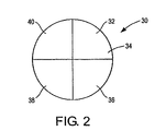
シャワーヘッド電極又は他のガス分配部材に対して、ゾーンの大きさ、形状及び数は様々に異なる。例えば、シャワーヘッド電極10は、使用状態における所望の最高電極性能に応じて、図1に示されるより多くのゾーン又は少ないゾーン、例えば約2個〜約24個のゾーンに分割される。ゾーンの数を増加することにより、出口面にわたるガス注入孔から流出するガス流量の均一性が向上する。図2は、各々がほぼ同一の大きさ及び形状を有する4個のゾーン32、34、36、38に分割された出口面31を含むシャワーヘッド電極30の別の好適な実施形態を示す。
For showerhead electrodes or other gas distribution members, the size, shape and number of zones vary. For example, the
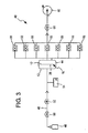
本実施形態において、シャワーヘッド電極10を通るガス流量は、以下に示す方法例で測定される。シャワーヘッド電極10は、ゾーン14〜26の各々を通るガス流量を測定するように構成されるガス流量測定装置40に設置される。図3は、2つのプレナム42、44を含むガス流量測定装置40の一実施形態を示す。プレナム42は入口面28の外周を密閉するように構成され、プレナム44はシャワーヘッド電極10の出口面12の外周を密閉するように構成される。ガス流量が測定されるシャワーヘッド電極10の表面積を最大化するために、2つのプレナム42、44は、シャワーヘッド電極10の直径を近似する直径を有する円形の外形を有するのが好ましい。
In the present embodiment, the gas flow rate through the
プレナム42は、ガスソース46、ガスライン48、遮断弁50、流量制御弁52及び圧力センサ54を具備するガス供給システムに接続する。
The
プレナム44の個別のゾーンの数、形状及び大きさは、シャワーヘッド電極10上でガス流量を測定されるゾーンの数、形状及び大きさに対応する。従って、図1に示すシャワーヘッド電極10の場合、プレナム44は、シャワーヘッド電極10のゾーン14〜26の形状及び大きさを有する7個のゾーンを含む。プレナム44のゾーンは、シャワーヘッド電極10の出口面12に垂直な方向に延在する壁を分割することにより規定される。個別のゾーンを通して総ガス流量を正確に測定できるように、プレナム44の各ゾーンは、周囲大気から密閉されると共に他のゾーンから密閉されるのが好ましい。
The number, shape and size of the individual zones of the
シャワーヘッド電極10の各ゾーンは、各流量測定器56に別個に接続されるのが好ましい。流量測定器56の出力は、遮断弁58及び真空ポンプ60に一括して接続されるのが好ましい。この構成により、所望のガス流量及び入口ガス圧がシャワーヘッド電極10に適用される。試験に使用されるガス流量条件及び圧力条件は、シャワーヘッド電極10を使用する半導体基板のプラズマ処理の間に適用される典型的な動作条件に類似するのが好ましい。
Each zone of the
一実施形態において、プレナム44のゾーンを介してシャワーヘッド電極10のゾーンを通って流出するガス流量を測定するために、プレナム42、44及びシャワーヘッド電極10が排気されるように、真空ポンプ60は起動され、弁58は開放される。所望の真空レベルに到達すると、流量測定器56が流量ゼロを示していることが確認される。
In one embodiment,
遮断弁50を開放してガスをガスソース46からプレナム42に流し、流量制御弁52を用いてガス流量を調整して、圧力センサ54における圧力測定値を取得する。この圧力測定値は、シャワーヘッド電極10に使用される典型的な動作条件と比較できる。システムは安定化され、個別のゾーンを通るガス流量が流量測定器56によって個別に又は同時に測定される。流量は、手動で記録されるか又は電子的に記録されるのが好ましい。
The
好適な実施形態において、ガス流量測定装置40はコントローラに電気的に接続される。コントローラは、遮断弁50、流量制御弁52、圧力センサ54、流量測定器56、遮断弁58及び真空ポンプ60から選択される任意の要素と制御通信を行う。コントローラは、圧力センサ54及び流量測定器56から値を読み取って弁の動作を制御できる。また、コントローラは、測定値を利用して数値計算を実行できる。
In a preferred embodiment, the gas
シャワーヘッド電極10の個別のゾーンを通るガス流量の測定後、ガス流量測定装置40からシャワーヘッド電極10を取り外すことができる。個別のゾーンを通った総ガス流量値に基づいて、シャワーヘッド電極10の出口面12において所望のガスフロー分配パターンを達成するために、いずれかのゾーンの透過率を調整することが望ましいかを判定できる。例えば、ゾーンに対する個別の総ガス流量値は互いに比較され、最大の総ガス流量測定値を判定できる。最大測定値より小さい総ガス流量値を有するゾーンに対しては、それらのゾーンの1つ以上のゾーンが好ましくは最大測定値にほぼ等しい総ガス流量を提供できるように、その1つ以上のゾーンの透過率が調整される。
After measuring the gas flow rate through the individual zones of the
他の実施形態においては、ガスが基板の処理面にわたって所望のフローパターンに分配されるように、ガス分配部材の異なるゾーン、例えば外周を規定するゾーンにおいて又はガス分配部材の中央部分において、より高いガス透過率を提供することが望ましい。 In other embodiments, higher in different zones of the gas distribution member, such as zones defining the outer periphery or in the central portion of the gas distribution member, so that the gas is distributed in a desired flow pattern across the processing surface of the substrate. It is desirable to provide gas permeability.
別の実施形態において、ゾーンに対する個別の総ガス流量値は、所望の値、例えば所定の値と比較される。全ての総ガス流量測定値が所望の値を超えない場合、所望のガスフロー分配パターンを達成するために、1つ以上のゾーンの透過率は所望の値に対して調整される。ゾーンに対する総ガス流量測定値のうち1つ以上の測定値が所望の値を超える場合、それらのゾーンのうち1つ以上のゾーンの透過率は最大測定値又は所望の値に対して調整される。そのような実施形態においては、プロセスガスが基板の処理面にわたって所望のフロー分配パターンに分配されるように、ガス分配部材が、1つ以上の選択されたゾーン、例えばガス分配部材の外周又は中央部分においてより高いガス透過率を有することが望ましい。 In another embodiment, the individual total gas flow values for the zone are compared to a desired value, eg, a predetermined value. If all the total gas flow measurements do not exceed the desired value, the permeability of one or more zones is adjusted to the desired value to achieve the desired gas flow distribution pattern. If one or more of the total gas flow measurements for a zone exceed a desired value, the transmittance of one or more of those zones is adjusted to the maximum or desired value. . In such embodiments, the gas distribution member may be in one or more selected zones, such as the periphery or center of the gas distribution member, such that the process gas is distributed in a desired flow distribution pattern across the processing surface of the substrate. It is desirable to have a higher gas permeability in the part.
ガス分配部材の1つ以上のゾーンの透過率が機械加工により調整された後、透過率の調整によってゾーンを通る所望の総ガス流量が提供されることを確認するために、ゾーンを通るガス流量がガス流量測定装置40において再測定される。ガス分配部材を更に機械加工することが望ましいと判定された場合、1つ以上のガス注入孔を変更するため及び/又は1つ以上の追加ガス注入孔を形成するために、ガス分配部材は、1つ以上の選択されたゾーンにおいて上述の手順に従って機械加工される。要望に応じて、この手順はガス分配部材の所望のガスフロー性能が達成されるまで繰り返される。
After the permeability of one or more zones of the gas distribution member has been adjusted by machining, the gas flow rate through the zone is verified to ensure that adjusting the permeability provides the desired total gas flow rate through the zone. Is measured again in the gas
一実施形態において、シャワーヘッド電極10の各ゾーンに対して、等しい所定の総ガス流量Q0が示される。ゾーンjにおいて測定された実際の総ガス流量はQjで表される。各ゾーンに対して、所定の流量と実際の流量との差ΔQjが算出できる。すなわち、ΔQj=Q0−Qjである。
In one embodiment, an equal predetermined total gas flow rate Q 0 is shown for each zone of the
本実施形態において、ゾーンに対する単位孔断面積当たりのガス流量、すなわち比率Qj/Ajを維持することが好ましい。Aはゾーンの基準総孔フロー断面積であり、Qはゾーンの総ガス流量である。関係式Qj/Aj=ΔQj/ΔAjを用いて、ゾーンに対する所望の総フロー断面積を達成するために、選択されたゾーンに追加されるフロー断面積ΔAjが算出される。所望のフロー断面積ΔAjは、1つ以上の既存の孔のフロー断面積を増加するか又はゾーン内に1つ以上の追加孔を追加することによってゾーンに追加される。上述のように、機械的ドリル法、超音波ドリル法又はレーザドリル法等の形成方法を使用して、1つ以上の孔のフロー断面積が量ΔAjの分だけ増加するように1つ以上の孔の大きさを調整するか又はΔAjに等しい総フロー断面積を有する1つ以上の孔を追加する。
実施例1
一例であるシャワーヘッド電極は7個のゾーンを含み、各ゾーンは、各々が0.025インチの基準径を有する240個の孔を含む。各ゾーンにおいて、Ajは0.118平方インチである。孔は任意の適切な形成技術により形成できる。所定の流量値が36.1sccm、Aj/Qjが3.263×10−3平方インチ/sccmであると仮定する。
In the present embodiment, it is preferable to maintain the gas flow rate per unit hole cross-sectional area with respect to the zone, that is, the ratio Q j / A j . A is the reference total hole flow cross-sectional area of the zone and Q is the total gas flow rate of the zone. Using the relationship Q j / A j = ΔQ j / ΔA j , the flow cross section ΔA j added to the selected zone is calculated to achieve the desired total flow cross section for the zone. The desired flow cross-sectional area ΔA j is added to the zone by increasing the flow cross-sectional area of one or more existing holes or adding one or more additional holes within the zone. As described above, one or more such that the flow cross-sectional area of one or more holes is increased by an amount ΔA j using a forming method such as mechanical drilling, ultrasonic drilling or laser drilling. Or add one or more holes with a total flow cross-sectional area equal to ΔA j .
Example 1
An example showerhead electrode includes seven zones, each zone including 240 holes each having a reference diameter of 0.025 inches. In each zone, A j is 0.118 square inches. The holes can be formed by any suitable forming technique. Assume that the predetermined flow value is 36.1 sccm and A j / Q j is 3.263 × 10 −3 square inches / sccm.
ガスはゾーンのガス注入孔を通して流され、ゾーンに対する総ガス流量測定値を表1に示す。また、表1は、各ゾーンが同一の総フロー断面積を有するように各ゾーンに追加される算出された孔径を示す。ゾーン6では、最大の総ガス流量Qjが測定された。従って、残りのゾーン1〜5及び7の各々のフロー断面積は、表1に示す合計直径を有する1つ以上の孔をゾーン1〜5及び7の各々に追加することにより、ゾーン6のフロー断面積に対して調整される。例えば、ゾーン1においては、直径が0.018インチである単一の追加孔が任意の適切な形成技術により形成される。ゾーン7においては、所望の直径0.044インチを有する単一の追加孔又は各々が所望の直径0.022インチを有する2つの追加孔が形成される。 The gas is flowed through the zone gas inlet and the total gas flow measurements for the zone are shown in Table 1. Table 1 also shows the calculated pore sizes added to each zone such that each zone has the same total flow cross-sectional area. In zone 6, the maximum total gas flow Qj was measured. Accordingly, the flow cross-sectional area of each of the remaining zones 1-5 and 7 is determined by adding one or more holes having the total diameter shown in Table 1 to each of zones 1-5 and 7, respectively. Adjusted for cross-sectional area. For example, in zone 1, a single additional hole having a diameter of 0.018 inches is formed by any suitable forming technique. In zone 7, a single additional hole having the desired diameter of 0.044 inches or two additional holes each having the desired diameter of 0.022 inches are formed.

実施例2
この実施例は、ガス分配部材内に形成されたガス注入孔の大きさの誤差がガス分配部材を通るガス流量に与える影響を説明する。ある特定の孔に対して、所望の孔の大きさ、例えば円形の孔の直径と実際の孔の大きさとの差によって誤差が与えられる。ガス分配部材の各ゾーンに対する実際の総ガス流量は個別に測定され、1つのゾーンに対する最大総ガス流量値又は1つ以上のゾーンに対する所望の総ガス流量、例えば所定の総ガス流量値と、そのゾーンに対する実際に測定された総ガス流量値との差が判定される。この差から、このゾーンの総ガス流量を最大値又は所望の値に増加するために、選択されたゾーン内に追加される追加フロー断面積ΔAjが判定できる。
Example 2
This example illustrates the effect of an error in the size of the gas injection hole formed in the gas distribution member on the gas flow rate through the gas distribution member. For a particular hole, an error is given by the desired hole size, eg, the difference between the diameter of the circular hole and the actual hole size. The actual total gas flow rate for each zone of the gas distribution member is measured individually and the maximum total gas flow value for one zone or the desired total gas flow value for one or more zones, eg, a predetermined total gas flow value, The difference from the actual measured total gas flow value for the zone is determined. From this difference, an additional flow cross-sectional area ΔA j can be determined that is added in the selected zone to increase the total gas flow in this zone to a maximum or desired value.
上述のように、ゾーン内に追加のフロー断面積を与えるために、機械的ドリル法、超音波ドリル法又はレーザドリル法等の任意の適切な技術によって、追加孔がゾーン内に形成される。孔を形成するために使用される特定の孔形成技術に関連する誤差を仮定する場合、追加孔の実際の直径は算出された直径とは異なる。追加された孔の大きさの誤差が孔を追加した結果得られるゾーンに対するフロー補正の精度に与える影響は、以下の方法で推定される。 As described above, additional holes are formed in the zone by any suitable technique, such as mechanical drilling, ultrasonic drilling, or laser drilling, to provide additional flow cross-sectional areas in the zone. Given the errors associated with the particular hole formation technique used to form the holes, the actual diameter of the additional holes is different from the calculated diameter. The influence of the added hole size error on the accuracy of the flow correction for the zone obtained as a result of adding the hole is estimated by the following method.
Axが、ゾーンxにおける実際の孔フロー断面積(孔の軸方向に垂直に測定される)の合計であると仮定する。ゾーンxの流量レベルを所望の流量レベルに増加するために追加する孔断面積はΔAである。この補正を達成するために、半径rを有する1つの円形孔がゾーンxに追加されると仮定した場合、以下の式が得られる。 Assume that A x is the sum of the actual hole flow cross-sectional area in zone x (measured perpendicular to the hole axial direction). The hole cross-sectional area added to increase the flow level of zone x to the desired flow level is ΔA. Assuming that one circular hole with radius r is added to zone x to achieve this correction, the following equation is obtained:
ΔA=πr2 (1)
ゾーンのフロー断面積の誤差(直径誤差を有する孔を追加した結果生じる)をεAとし、追加された孔の半径の誤差をδとする場合、以下の式が得られる。
ΔA = πr 2 (1)
If the error in the flow cross-sectional area of the zone (resulting from adding a hole with a diameter error) is εA and the error in the radius of the added hole is δ, the following equation is obtained.
|π(r+δ)2−ΔA|<εA (2)
式を展開して並び替え、式(1)を用いてδ2の項を外す(無縁根であるため)ことにより、以下の式が得られる。
| Π (r + δ) 2 −ΔA | <εA (2)
By expanding and rearranging the equations and removing the term of δ 2 using Equation (1) (because it is an edgeless root), the following equation is obtained.
|2πrδ/A|<ε (3)
ゾーンxがn個の孔を有し、各孔が半径r0を有し、n個の孔に対する総フロー断面積Aがnπr0 2に等しいと仮定する。式(1)及び(3)を組み合わせることにより、以下の式が得られる。
| 2πrδ / A | <ε (3)
Assume that zone x has n holes, each hole has a radius r 0 , and the total flow cross-sectional area A for n holes is equal to nπr 0 2 . By combining the formulas (1) and (3), the following formula is obtained.
|2rδ/(nr0 2)|<ε (4)
式中、εは結果的に生じる流量誤差である。
| 2rδ / (nr 0 2 ) | <ε (4)
Where ε is the resulting flow error.
式4は、大きさの誤差δを有する孔を追加した結果生じるゾーンxに対するフロー断面積の誤差がδに正比例し、ゾーン内の孔の数n及び既存の孔の半径r0の二乗に反比例することを示す。従って、ある特定の値δ及びn個の孔に対して孔の半径r0を増加することにより、孔を追加したゾーンに対する結果的に生じる流量誤差εは減少する。 Equation 4 shows that the flow cross-sectional area error for zone x resulting from adding a hole with size error δ is directly proportional to δ and inversely proportional to the number of holes n in the zone and the square of the existing hole radius r 0. Indicates to do. Thus, by increasing the hole radius r 0 for a particular value δ and n holes, the resulting flow error ε for the zone with the added holes is reduced.
一実施形態において、r0=0.0125インチ及びr=0.020インチと仮定して、n及びδを変化させる。算出結果を表2に示す。 In one embodiment, n and δ are varied assuming r 0 = 0.0125 inch and r = 0.020 inch. Table 2 shows the calculation results.
表2に示すように、δのある特定の値に対して、ガス分配部材のゾーン内の孔の総数を増加することにより、ある特定の孔の大きさの誤差に対して結果的に生じるゾーンの流量誤差εは減少する。換言すると、所望のガス流量を十分に達成するゾーン内の孔の総数を増加することにより、ある特定の全体的な流量誤差を達成できる追加孔の大きさの精度を低下できる。従って、機械的ドリル法等の精度の低い孔形成技術は、1つ以上のゾーンに対する所望の全体的な流量誤差を有する追加孔を形成するのに適している。例えば、1つ以上の追加孔は、100個の孔を有するゾーンにおいて機械的ドリル法により形成されてもよく、その一方で、レーザドリル法等の精度の高い形成技術は、40個の孔のみを有するゾーンにおいて1つ以上の追加孔を形成するのに望ましい。追加孔に関連する流量誤差を減少するために、孔により追加されるΔAがゾーン内の孔の総断面積に対して大きくならないように、ゾーン内の孔の数を増加できる。 As shown in Table 2, by increasing the total number of holes in the zone of the gas distribution member for a given value of δ, the resulting zone for a given hole size error The flow error ε decreases. In other words, by increasing the total number of holes in the zone that adequately achieves the desired gas flow rate, the accuracy of additional hole sizes that can achieve a certain overall flow error can be reduced. Thus, less accurate hole formation techniques such as mechanical drilling are suitable for forming additional holes having the desired overall flow error for one or more zones. For example, one or more additional holes may be formed by mechanical drilling in a zone having 100 holes, while highly precise forming techniques such as laser drilling are only 40 holes. It is desirable to form one or more additional holes in a zone having To reduce the flow error associated with the additional holes, the number of holes in the zone can be increased so that the ΔA added by the holes does not increase relative to the total cross-sectional area of the holes in the zone.
また、表2に示すように、δの値が0.001インチで孔が100個の場合、孔直径の誤差から生じる値εは理想的な流量の0.26%である。追加孔の0.005インチの半径誤差(すなわち、0.010の直径誤差)に対して、ゾーンの流量誤差は1.3%のみである。この算出は、追加孔の直径誤差が容易に達成される0.005インチの場合、40個の孔を有するゾーンは約3%(すなわち、δ=0.0025インチ及びε=0.016)の誤差以内で補正可能であることを更に示す。 As shown in Table 2, when the value of δ is 0.001 inch and there are 100 holes, the value ε resulting from the hole diameter error is 0.26% of the ideal flow rate. For a 0.005 inch radius error (ie, 0.010 diameter error) in the additional hole, the zone flow error is only 1.3%. This calculation shows that for a 0.005 inch where the diameter error of the additional hole is easily achieved, a zone with 40 holes is about 3% (ie δ = 0.005 inch and ε = 0.016). It is further shown that the correction can be made within the error.
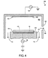
図4は、中密度プラズマを形成できる容量結合型プラズマ処理チャンバ102を具備するプラズマ処理装置100の一例を示す。プラズマ処理チャンバ102はチャンバ壁103を含む。地面への電気的経路を提供するために、チャンバ壁103はアルミニウム等から構成され且つ電気的に接地される。
FIG. 4 shows an example of a
プラズマ処理装置100は、チャンバ壁及びライナ等の構成要素を含むことができる。構成要素は保護物質から構成され且つ/又は保護被膜を含み、プラズマ処理中の浸食及び腐食に対して耐性がある。構成要素の例は、例えば、本出願の譲受人と同一の譲受人に譲渡され本明細書に参考として全ての内容が取り入れられている米国特許第6,408,786号公報、第6,464,843号公報、第6,506,254号公報、第6,620,520号公報、第6,780,787号公報、第6,805,952号公報及び第6,830,622号公報に説明される。
The
プラズマ処理チャンバ102は、半導体基板をプラズマ処理チャンバ102の内側及び外側に搬送するためにチャンバ壁103内に設けられたウエハ搬送溝118を含む。
The
プラズマ処理チャンバ102は底面108を有する上部電極104を含む。本明細書に参考として全ての内容が取り入れられている米国特許第6,391,787号公報に説明されるように、底面108は平坦であるか又は段差を含む。上部電極104は、一体型電極又は組立型電極であってもよい。上部電極104は、プロセスガスをプラズマ処理チャンバ内に分配するためのガス流路を含むシャワーヘッド電極であってもよい。上部電極は、シリコン(例えば、単結晶シリコン、多結晶シリコン又はアモルファスシリコン)又は炭化ケイ素から成る。装置100は、プロセスガスを上部電極104に供給するためのガスソース(不図示)を含む。
The
本出願の譲受人と同一の譲受人に譲渡され本明細書に参考として全ての内容が取り入れられている米国特許第6,073,577号公報に説明されるように、上部電極104はエラストマ結合型電極アセンブリ内に設けられる。
As described in US Pat. No. 6,073,577, assigned to the same assignee as the assignee of the present application, the entire contents of which are incorporated herein by reference, the
上部電極104は、RF電源106によりマッチングネットワークを介して電力が供給されるのが好ましい。別の実施形態においては、以下に説明されるように、プラズマ処理チャンバ102の底部電極によって供給される電力の戻り経路を提供するために、上部電極104は接地される。
The
装置100は、プラズマチャンバの選択された領域内にプラズマを閉じ込めるためのプラズマ閉じ込めリングアセンブリを含む。適切なアセンブリは、例えば、各々が本明細書に参考として全ての内容が取り入れられている米国特許第5,534,751号公報、第5,998,932号公報及び第6,527,911号公報において説明される。
The
図4に示す装置100の実施形態において、プロセスガスは、上部電極104と基板支持体111上で支持されるシリコンウエハ等の半導体基板10との間で発達したプラズマ領域において、プラズマ処理チャンバ102内に供給される。基板支持体111は、静電クランプ力によって基板支持体上に半導体基板10を固定する静電チャック114を含むのが好ましい。静電チャック114は底面電極として作用し、RF電源116により(通常はマッチングネットワークを介して)バイアスをかけられるのが好ましい。静電チャック114の上面115は、半導体基板10とほぼ同一の直径を有するのが好ましい。
In the embodiment of the
ポンプ(不図示)は、プラズマ処理チャンバ102の内側で所望の真空圧を維持するように構成される。ガスは、一般に矢印110により表される方向にポンプによって吸引される。
A pump (not shown) is configured to maintain a desired vacuum pressure inside the
使用可能な平行平板型プラズマ反応器の一例は、二周波数プラズマエッチング反応器(例えば、本出願の譲受人と同一の譲受人に譲渡され本明細書に参考として全ての内容が取り入れられている米国特許第6,090,304号公報を参照)である。そのような反応器において、エッチングガスはガス源からシャワーヘッド電極に供給され、プラズマは、2つのRF電源からシャワーヘッド電極及び/又は底部電極にRFエネルギーを供給することによって反応器内で作成される。あるいは、シャワーヘッド電極は電気的に接地され、2つの異なる周波数のRFエネルギーは底部電極に供給される。 An example of a parallel plate plasma reactor that can be used is a dual frequency plasma etch reactor (eg, the United States assigned to the same assignee as the assignee of the present application and incorporated herein in its entirety by reference). (See Japanese Patent No. 6,090,304). In such a reactor, an etching gas is supplied from a gas source to the showerhead electrode, and a plasma is created in the reactor by supplying RF energy from two RF power sources to the showerhead electrode and / or the bottom electrode. The Alternatively, the showerhead electrode is electrically grounded and two different frequencies of RF energy are supplied to the bottom electrode.
本発明の原理、好適な実施形態及び動作モードを上述した。しかしながら、本発明は、上述の特定の実施形態に限定されると解釈されるべきではない。従って、上述の実施形態は、例示であって限定的ではないと見なされるべきである。また、添付の請求の範囲に規定される本発明の範囲から逸脱することなく、当業者によりそれらの実施形態において変形が実施されてもよいことが理解されるべきである。 The principles, preferred embodiments and modes of operation of the present invention have been described above. However, the present invention should not be construed as limited to the particular embodiments described above. Accordingly, the above-described embodiments are to be regarded as illustrative and not restrictive. In addition, it should be understood that variations may be made in those embodiments by those skilled in the art without departing from the scope of the invention as defined in the appended claims.
Claims (17)
前記ガス分配部材の対向する入口面と出口面との間に延在するガス注入孔を形成することと、
前記ガス分配部材の複数のゾーンの各ゾーンに対して、前記出口面において前記ガス注入孔から流出する総ガス流量を測定することと、
前記出口面において所望のガスフロー分配パターンを達成するために、前記ゾーンの各ゾーンに対して測定された前記総ガス流量に基づいて、前記ゾーンの1つ以上のゾーンにおいて前記ガス分配部材のガス透過率を調整することとを有する方法。A method of manufacturing a gas distribution member for a plasma processing apparatus,
Forming a gas injection hole extending between opposing inlet and outlet faces of the gas distribution member;
For each zone of the plurality of zones of the gas distribution member, measuring a total gas flow rate flowing out of the gas injection hole at the outlet surface;
Based on the total gas flow measured for each zone of the zone, the gas of the gas distribution member in one or more zones of the zone to achieve a desired gas flow distribution pattern at the outlet face. Adjusting the transmittance.
前記測定された総ガス流量のうち、最大の総ガス流量を有する前記ゾーンを第1のゾーンとし、前記第1のゾーンの総ガス流量と前記ゾーンの少なくとも第2のゾーンを通る総ガス流量との差を判定することと、
前記第2のゾーンにおいて、(i)変更されたガス注入孔を通るガス流量を増加するために、少なくとも1つのガス注入孔を変更及び/又は(ii)前記第1のゾーンの前記ガス透過率に対して前記第2のゾーンの前記ガス透過率を調整するために少なくとも1つの追加ガス注入孔を形成することとを含む請求項1記載の方法。The adjustment of the gas permeability of the gas distribution member is
Of the total gas flow rate that is the measurement, the zone having a total gas flow of up to the first zone, the total gas flow through at least a second zone before Symbol said zone and total gas flow rate of the first zone Determining the difference between
In the second zone, (i) at least one gas injection hole is changed and / or (ii) the gas permeability of the first zone to increase the gas flow rate through the changed gas injection hole. Forming at least one additional gas injection hole to adjust the gas permeability of the second zone relative to the second zone.
所望の総ガス流量と前記ゾーンの各ゾーンを通る前記測定された総ガス流量との差を判定することと、
前記1つ以上のゾーンの各ゾーンにおいて、(i)変更されたガス注入孔を通るガス流量を増加するために、少なくとも1つのガス注入孔を変更及び/又は(ii)前記所望の総ガス流量に基づいて前記1つ以上のゾーンの前記ガス透過率を調整するために少なくとも1つの追加ガス注入孔を形成することとを含む請求項1記載の方法。The adjustment of the gas permeability of the gas distribution member is
Determining a difference between a desired total gas flow rate and the measured total gas flow rate through each of the zones;
In each zone of the one or more zones, (i) changing at least one gas inlet and / or (ii) the desired total gas flow to increase the gas flow through the changed gas inlet. Forming at least one additional gas injection hole to adjust the gas permeability of the one or more zones based on the method.
ガス分配部材の出口面においてガスが流出するように、前記ガス分配部材のガス注入孔を通してガスを流すことと、
前記ガス分配部材の複数のゾーンの各ゾーンに対して、前記ガス注入孔から流出する総ガス流量を測定することと、
前記出口面において所望のガス流れ分配パターンを達成するために、前記ゾーンの各ゾーンに対して測定された前記総ガス流量に基づいて、前記ゾーンの1つ以上のゾーンにおいて前記ガス分配部材のガス透過率を調整することとを有する方法。A method of adjusting the gas permeability of a gas distribution member for a plasma processing apparatus,
Flowing the gas through the gas injection hole of the gas distribution member such that the gas flows out at the outlet surface of the gas distribution member;
Measuring a total gas flow rate flowing out of the gas injection hole for each of a plurality of zones of the gas distribution member;
In order to achieve a desired gas flow distribution pattern at the outlet face, the gas distribution member gas in one or more zones of the zone based on the total gas flow measured for each of the zones. Adjusting the transmittance.
前記測定された総ガス流量のうち、最大の総ガス流量を有する前記ゾーンを第1のゾーンとし、前記第1のゾーンの総ガス流量と前記ゾーンの少なくとも第2のゾーンを通る総ガス流量との差を判定することと、
前記第2のゾーンにおいて、(i)変更されたガス注入孔を通るガス流量を増加するために、少なくとも1つのガス注入孔を変更及び/又は(ii)前記第1のゾーンの前記ガス透過率に対して前記第2のゾーンの前記ガス透過率を調整するために少なくとも1つの追加ガス注入孔を形成することとを含む請求項12記載の方法。The adjustment of the gas permeability of the gas distribution member is
Of the total gas flow rate that is the measurement, the zone having a total gas flow of up to the first zone, the total gas flow through at least a second zone before Symbol said zone and total gas flow rate of the first zone Determining the difference between
In the second zone, (i) at least one gas injection hole is changed and / or (ii) the gas permeability of the first zone to increase the gas flow rate through the changed gas injection hole. Forming at least one additional gas injection hole to adjust the gas permeability of the second zone relative to the second zone.
所望の総ガス流量と前記ゾーンの各ゾーンを通る前記測定された総ガス流量との差を判定することと、
前記1つ以上のゾーンの各ゾーンにおいて、(i)変更されたガス注入孔を通るガス流量を増加するために、少なくとも1つのガス注入孔を変更及び/又は(ii)前記1つ以上のゾーンの前記ガス透過率を調整するために少なくとも1つの追加ガス注入孔を形成することとを含む請求項12記載の方法。The adjustment of the gas permeability of the gas distribution member is
Determining a difference between a desired total gas flow rate and the measured total gas flow rate through each of the zones;
In each zone of the one or more zones, (i) changing at least one gas injection hole and / or (ii) changing the gas flow rate through the changed gas injection hole and / or (ii) the one or more zones. 13. The method of claim 12, comprising forming at least one additional gas injection hole to adjust the gas permeability of the gas.
Applications Claiming Priority (3)
| Application Number | Priority Date | Filing Date | Title |
|---|---|---|---|
| US11/057,433 US7480974B2 (en) | 2005-02-15 | 2005-02-15 | Methods of making gas distribution members for plasma processing apparatuses |
| US11/057,433 | 2005-02-15 | ||
| PCT/US2006/004284 WO2006088697A2 (en) | 2005-02-15 | 2006-02-08 | Methods of making gas distribution members for plasma processing apparatuses |
Publications (3)
| Publication Number | Publication Date |
|---|---|
| JP2008537628A JP2008537628A (en) | 2008-09-18 |
| JP2008537628A5 JP2008537628A5 (en) | 2009-03-26 |
| JP4814259B2 true JP4814259B2 (en) | 2011-11-16 |
Family
ID=36814467
Family Applications (1)
| Application Number | Title | Priority Date | Filing Date |
|---|---|---|---|
| JP2007555173A Expired - Fee Related JP4814259B2 (en) | 2005-02-15 | 2006-02-08 | Method for manufacturing gas distribution member for plasma processing apparatus and method for adjusting gas permeability of the member |
Country Status (6)
| Country | Link |
|---|---|
| US (2) | US7480974B2 (en) |
| JP (1) | JP4814259B2 (en) |
| KR (1) | KR101323025B1 (en) |
| CN (1) | CN101495268B (en) |
| TW (1) | TWI378152B (en) |
| WO (1) | WO2006088697A2 (en) |
Families Citing this family (17)
| Publication number | Priority date | Publication date | Assignee | Title |
|---|---|---|---|---|
| US7480974B2 (en) * | 2005-02-15 | 2009-01-27 | Lam Research Corporation | Methods of making gas distribution members for plasma processing apparatuses |
| US8702866B2 (en) * | 2006-12-18 | 2014-04-22 | Lam Research Corporation | Showerhead electrode assembly with gas flow modification for extended electrode life |
| JP4849247B2 (en) * | 2006-12-22 | 2012-01-11 | 三菱マテリアル株式会社 | Composite silicon electrode with small in-plane variation of specific resistance value and manufacturing method thereof |
| US8216419B2 (en) * | 2008-03-28 | 2012-07-10 | Bridgelux, Inc. | Drilled CVD shower head |
| US8961689B2 (en) * | 2008-03-26 | 2015-02-24 | Gtat Corporation | Systems and methods for distributing gas in a chemical vapor deposition reactor |
| WO2009120859A1 (en) * | 2008-03-26 | 2009-10-01 | Gt Solar, Inc. | Gold-coated polysilicon reactor system and method |
| US20100071210A1 (en) * | 2008-09-24 | 2010-03-25 | Applied Materials, Inc. | Methods for fabricating faceplate of semiconductor apparatus |
| KR101460555B1 (en) * | 2008-12-29 | 2014-11-14 | 주식회사 케이씨텍 | Showerhead and atomic layer deposition apparatus |
| JP5336968B2 (en) * | 2009-07-30 | 2013-11-06 | 東京エレクトロン株式会社 | Electrode for plasma processing apparatus and plasma processing apparatus |
| US9245717B2 (en) | 2011-05-31 | 2016-01-26 | Lam Research Corporation | Gas distribution system for ceramic showerhead of plasma etch reactor |
| US8883029B2 (en) | 2013-02-13 | 2014-11-11 | Lam Research Corporation | Method of making a gas distribution member for a plasma processing chamber |
| US9275840B2 (en) | 2014-01-25 | 2016-03-01 | Yuri Glukhoy | Method for providing uniform distribution of plasma density in a plasma treatment apparatus |
| US9484190B2 (en) | 2014-01-25 | 2016-11-01 | Yuri Glukhoy | Showerhead-cooler system of a semiconductor-processing chamber for semiconductor wafers of large area |
| US9570289B2 (en) * | 2015-03-06 | 2017-02-14 | Lam Research Corporation | Method and apparatus to minimize seam effect during TEOS oxide film deposition |
| JP6421294B1 (en) * | 2017-05-25 | 2018-11-14 | 株式会社三井E&Sマシナリー | Shower head machining tool and method for manufacturing shower head machining tool |
| CN115485413A (en) * | 2020-04-29 | 2022-12-16 | 朗姆研究公司 | Grouping features for showerhead in substrate processing system |
| JP7563846B2 (en) | 2020-12-21 | 2024-10-08 | 東京エレクトロン株式会社 | Flow rate measuring method and substrate processing apparatus |
Citations (5)
| Publication number | Priority date | Publication date | Assignee | Title |
|---|---|---|---|---|
| JPH0718441U (en) * | 1993-09-10 | 1995-03-31 | 日新電機株式会社 | Thin film vapor deposition equipment |
| JP2001185494A (en) * | 1999-12-27 | 2001-07-06 | Toshiba Corp | Equipment for magnetron plasma treatment and method of plasma treatment |
| JP2002064084A (en) * | 2000-08-17 | 2002-02-28 | Sumitomo Metal Ind Ltd | Gas introducing equipment for plasma treatment and plasma treating method |
| JP2002155366A (en) * | 2000-11-15 | 2002-05-31 | Tokyo Electron Ltd | Method and device of leaf type heat treatment |
| WO2005019496A1 (en) * | 2003-08-20 | 2005-03-03 | Veeco Instruments Inc. | Alkyl push flow for vertical flow rotating disk reactors |
Family Cites Families (36)
| Publication number | Priority date | Publication date | Assignee | Title |
|---|---|---|---|---|
| US5539609A (en) * | 1992-12-02 | 1996-07-23 | Applied Materials, Inc. | Electrostatic chuck usable in high density plasma |
| US5928427A (en) * | 1994-12-16 | 1999-07-27 | Hwang; Chul-Ju | Apparatus for low pressure chemical vapor deposition |
| US5534751A (en) * | 1995-07-10 | 1996-07-09 | Lam Research Corporation | Plasma etching apparatus utilizing plasma confinement |
| US5644467A (en) * | 1995-09-28 | 1997-07-01 | Applied Materials, Inc. | Method and structure for improving gas breakdown resistance and reducing the potential of arcing in a electrostatic chuck |
| US6108189A (en) * | 1996-04-26 | 2000-08-22 | Applied Materials, Inc. | Electrostatic chuck having improved gas conduits |
| US6013155A (en) * | 1996-06-28 | 2000-01-11 | Lam Research Corporation | Gas injection system for plasma processing |
| US6090304A (en) * | 1997-08-28 | 2000-07-18 | Lam Research Corporation | Methods for selective plasma etch |
| US6537418B1 (en) * | 1997-09-19 | 2003-03-25 | Siemens Aktiengesellschaft | Spatially uniform gas supply and pump configuration for large wafer diameters |
| US6098568A (en) * | 1997-12-01 | 2000-08-08 | Applied Materials, Inc. | Mixed frequency CVD apparatus |
| KR19990065416A (en) * | 1998-01-13 | 1999-08-05 | 윤종용 | Chamber equipment for manufacturing semiconductor device including shower head |
| US6464843B1 (en) * | 1998-03-31 | 2002-10-15 | Lam Research Corporation | Contamination controlling method and apparatus for a plasma processing chamber |
| US6106663A (en) * | 1998-06-19 | 2000-08-22 | Lam Research Corporation | Semiconductor process chamber electrode |
| US5998932A (en) * | 1998-06-26 | 1999-12-07 | Lam Research Corporation | Focus ring arrangement for substantially eliminating unconfined plasma in a plasma processing chamber |
| US6073577A (en) * | 1998-06-30 | 2000-06-13 | Lam Research Corporation | Electrode for plasma processes and method for manufacture and use thereof |
| JP4162773B2 (en) * | 1998-08-31 | 2008-10-08 | 東京エレクトロン株式会社 | Plasma processing apparatus and detection window |
| KR20000010029U (en) * | 1998-11-14 | 2000-06-15 | 김영환 | Shower Head for Semiconductor Deposition Equipment |
| US6123775A (en) * | 1999-06-30 | 2000-09-26 | Lam Research Corporation | Reaction chamber component having improved temperature uniformity |
| US6451157B1 (en) * | 1999-09-23 | 2002-09-17 | Lam Research Corporation | Gas distribution apparatus for semiconductor processing |
| US6408786B1 (en) * | 1999-09-23 | 2002-06-25 | Lam Research Corporation | Semiconductor processing equipment having tiled ceramic liner |
| KR100338955B1 (en) * | 1999-12-31 | 2002-05-31 | 박종섭 | Apparatus for supply of gas in dry etching process of semiconductor |
| US6444040B1 (en) * | 2000-05-05 | 2002-09-03 | Applied Materials Inc. | Gas distribution plate |
| US6506254B1 (en) * | 2000-06-30 | 2003-01-14 | Lam Research Corporation | Semiconductor processing equipment having improved particle performance |
| JP4484185B2 (en) * | 2000-08-29 | 2010-06-16 | コバレントマテリアル株式会社 | Chemical vapor deposition method for silicon semiconductor substrate |
| US6391787B1 (en) * | 2000-10-13 | 2002-05-21 | Lam Research Corporation | Stepped upper electrode for plasma processing uniformity |
| US6797639B2 (en) * | 2000-11-01 | 2004-09-28 | Applied Materials Inc. | Dielectric etch chamber with expanded process window |
| US6805952B2 (en) * | 2000-12-29 | 2004-10-19 | Lam Research Corporation | Low contamination plasma chamber components and methods for making the same |
| US6620520B2 (en) * | 2000-12-29 | 2003-09-16 | Lam Research Corporation | Zirconia toughened ceramic components and coatings in semiconductor processing equipment and method of manufacture thereof |
| US20020127853A1 (en) * | 2000-12-29 | 2002-09-12 | Hubacek Jerome S. | Electrode for plasma processes and method for manufacture and use thereof |
| US6852167B2 (en) * | 2001-03-01 | 2005-02-08 | Micron Technology, Inc. | Methods, systems, and apparatus for uniform chemical-vapor depositions |
| US6830622B2 (en) * | 2001-03-30 | 2004-12-14 | Lam Research Corporation | Cerium oxide containing ceramic components and coatings in semiconductor processing equipment and methods of manufacture thereof |
| US6527911B1 (en) * | 2001-06-29 | 2003-03-04 | Lam Research Corporation | Configurable plasma volume etch chamber |
| US6780787B2 (en) * | 2002-03-21 | 2004-08-24 | Lam Research Corporation | Low contamination components for semiconductor processing apparatus and methods for making components |
| US7543547B1 (en) * | 2002-07-31 | 2009-06-09 | Lam Research Corporation | Electrode assembly for plasma processing apparatus |
| JP2005019606A (en) * | 2003-06-25 | 2005-01-20 | Anelva Corp | Device for fixing gas shower head or target plate to electrode in plasma treatment apparatus |
| US7645341B2 (en) * | 2003-12-23 | 2010-01-12 | Lam Research Corporation | Showerhead electrode assembly for plasma processing apparatuses |
| US7480974B2 (en) * | 2005-02-15 | 2009-01-27 | Lam Research Corporation | Methods of making gas distribution members for plasma processing apparatuses |
-
2005
- 2005-02-15 US US11/057,433 patent/US7480974B2/en not_active Expired - Fee Related
-
2006
- 2006-02-08 KR KR1020077021227A patent/KR101323025B1/en active IP Right Grant
- 2006-02-08 CN CN2006800080809A patent/CN101495268B/en active Active
- 2006-02-08 JP JP2007555173A patent/JP4814259B2/en not_active Expired - Fee Related
- 2006-02-08 WO PCT/US2006/004284 patent/WO2006088697A2/en active Application Filing
- 2006-02-15 TW TW095105083A patent/TWI378152B/en not_active IP Right Cessation
-
2009
- 2009-01-07 US US12/349,803 patent/US20090120583A1/en not_active Abandoned
Patent Citations (5)
| Publication number | Priority date | Publication date | Assignee | Title |
|---|---|---|---|---|
| JPH0718441U (en) * | 1993-09-10 | 1995-03-31 | 日新電機株式会社 | Thin film vapor deposition equipment |
| JP2001185494A (en) * | 1999-12-27 | 2001-07-06 | Toshiba Corp | Equipment for magnetron plasma treatment and method of plasma treatment |
| JP2002064084A (en) * | 2000-08-17 | 2002-02-28 | Sumitomo Metal Ind Ltd | Gas introducing equipment for plasma treatment and plasma treating method |
| JP2002155366A (en) * | 2000-11-15 | 2002-05-31 | Tokyo Electron Ltd | Method and device of leaf type heat treatment |
| WO2005019496A1 (en) * | 2003-08-20 | 2005-03-03 | Veeco Instruments Inc. | Alkyl push flow for vertical flow rotating disk reactors |
Also Published As
| Publication number | Publication date |
|---|---|
| TW200639268A (en) | 2006-11-16 |
| TWI378152B (en) | 2012-12-01 |
| US20060180275A1 (en) | 2006-08-17 |
| WO2006088697A2 (en) | 2006-08-24 |
| JP2008537628A (en) | 2008-09-18 |
| US7480974B2 (en) | 2009-01-27 |
| KR101323025B1 (en) | 2013-11-04 |
| WO2006088697A3 (en) | 2009-04-16 |
| KR20070103508A (en) | 2007-10-23 |
| CN101495268A (en) | 2009-07-29 |
| CN101495268B (en) | 2011-06-08 |
| US20090120583A1 (en) | 2009-05-14 |
Similar Documents
| Publication | Publication Date | Title |
|---|---|---|
| JP4814259B2 (en) | Method for manufacturing gas distribution member for plasma processing apparatus and method for adjusting gas permeability of the member | |
| KR101278863B1 (en) | Methods for verifying gas flow rates from a gas supply system into a plasma processing chamber | |
| TWI609442B (en) | Variable showerhead flow by varying internal baffle conductance | |
| US10366865B2 (en) | Gas distribution system for ceramic showerhead of plasma etch reactor | |
| JP5891300B2 (en) | Gas distribution showerhead for inductively coupled plasma etching reactor | |
| TWI418963B (en) | Gas flow control by differential pressure measurements | |
| JP5463536B2 (en) | Shower plate and manufacturing method thereof, and plasma processing apparatus, plasma processing method and electronic device manufacturing method using the shower plate | |
| JP5268626B2 (en) | Plasma processing equipment | |
| US10229844B2 (en) | Gas supply system, gas supply control method and gas replacement method | |
| EP0768702A1 (en) | Gas injection slit nozzle for a plasma process reactor | |
| US7017652B2 (en) | Method and apparatus for transferring heat from a substrate to a chuck | |
| KR20090024075A (en) | Substrate mounting table, substrate processing apparatus and temperature control method | |
| JP3913244B2 (en) | Substrate processing method | |
| US6577113B2 (en) | Apparatus and method for measuring substrate biasing during plasma processing of a substrate | |
| TW202140841A (en) | Gas distribution faceplate with oblique flow paths | |
| JP2006120872A (en) | Gaseous diffusion plate | |
| JP4611217B2 (en) | Wafer mounting electrode | |
| US11959793B2 (en) | Flow metrology calibration for improved processing chamber matching in substrate processing systems | |
| TW202225473A (en) | Methods of seasoning process chambers | |
| US20120000607A1 (en) | Mass flow control system, plasma processing apparatus, and flow control method | |
| JP2006253204A (en) | Test piece installation electrode of plasma processing apparatus | |
| JPH11158617A (en) | Sputtering method and sputtering device | |
| US20200035540A1 (en) | Systems and methods for pedestal configuration | |
| WO2010036657A2 (en) | Methods for fabricating faceplate of semiconductor apparatus | |
| JP2014529884A (en) | Mounting device for mounting patterned wafers |
Legal Events
| Date | Code | Title | Description |
|---|---|---|---|
| A521 | Request for written amendment filed |
Free format text: JAPANESE INTERMEDIATE CODE: A523 Effective date: 20090205 |
|
| A621 | Written request for application examination |
Free format text: JAPANESE INTERMEDIATE CODE: A621 Effective date: 20090205 |
|
| A131 | Notification of reasons for refusal |
Free format text: JAPANESE INTERMEDIATE CODE: A131 Effective date: 20110221 |
|
| A521 | Request for written amendment filed |
Free format text: JAPANESE INTERMEDIATE CODE: A523 Effective date: 20110510 |
|
| TRDD | Decision of grant or rejection written | ||
| A01 | Written decision to grant a patent or to grant a registration (utility model) |
Free format text: JAPANESE INTERMEDIATE CODE: A01 Effective date: 20110812 |
|
| A01 | Written decision to grant a patent or to grant a registration (utility model) |
Free format text: JAPANESE INTERMEDIATE CODE: A01 |
|
| A61 | First payment of annual fees (during grant procedure) |
Free format text: JAPANESE INTERMEDIATE CODE: A61 Effective date: 20110825 |
|
| R150 | Certificate of patent or registration of utility model |
Ref document number: 4814259 Country of ref document: JP Free format text: JAPANESE INTERMEDIATE CODE: R150 Free format text: JAPANESE INTERMEDIATE CODE: R150 |
|
| FPAY | Renewal fee payment (event date is renewal date of database) |
Free format text: PAYMENT UNTIL: 20140902 Year of fee payment: 3 |
|
| R250 | Receipt of annual fees |
Free format text: JAPANESE INTERMEDIATE CODE: R250 |
|
| R250 | Receipt of annual fees |
Free format text: JAPANESE INTERMEDIATE CODE: R250 |
|
| R250 | Receipt of annual fees |
Free format text: JAPANESE INTERMEDIATE CODE: R250 |
|
| R250 | Receipt of annual fees |
Free format text: JAPANESE INTERMEDIATE CODE: R250 |
|
| R250 | Receipt of annual fees |
Free format text: JAPANESE INTERMEDIATE CODE: R250 |
|
| LAPS | Cancellation because of no payment of annual fees |