JP4812089B2 - Printing apparatus and connection method thereof - Google Patents
Printing apparatus and connection method thereof Download PDFInfo
- Publication number
- JP4812089B2 JP4812089B2 JP2006048974A JP2006048974A JP4812089B2 JP 4812089 B2 JP4812089 B2 JP 4812089B2 JP 2006048974 A JP2006048974 A JP 2006048974A JP 2006048974 A JP2006048974 A JP 2006048974A JP 4812089 B2 JP4812089 B2 JP 4812089B2
- Authority
- JP
- Japan
- Prior art keywords
- connection
- printing apparatus
- pin code
- connection information
- printing
- Prior art date
- Legal status (The legal status is an assumption and is not a legal conclusion. Google has not performed a legal analysis and makes no representation as to the accuracy of the status listed.)
- Expired - Fee Related
Links
Images


Classifications
-
- H—ELECTRICITY
- H04—ELECTRIC COMMUNICATION TECHNIQUE
- H04W—WIRELESS COMMUNICATION NETWORKS
- H04W76/00—Connection management
- H04W76/10—Connection setup
- H04W76/11—Allocation or use of connection identifiers
-
- H—ELECTRICITY
- H04—ELECTRIC COMMUNICATION TECHNIQUE
- H04W—WIRELESS COMMUNICATION NETWORKS
- H04W28/00—Network traffic management; Network resource management
- H04W28/16—Central resource management; Negotiation of resources or communication parameters, e.g. negotiating bandwidth or QoS [Quality of Service]
- H04W28/18—Negotiating wireless communication parameters
-
- H—ELECTRICITY
- H04—ELECTRIC COMMUNICATION TECHNIQUE
- H04W—WIRELESS COMMUNICATION NETWORKS
- H04W76/00—Connection management
- H04W76/10—Connection setup
- H04W76/14—Direct-mode setup
Description
本発明は、端末との間で接続可能な印刷装置及びその接続方法に関するものである。 The present invention relates to connecting a printing device and a connection method between the end end.
近年、Bluetooth(登録商標)等の無線機能を搭載する携帯端末が多数商品化されており、これらの端末はパーソナルコンピュータ(PC)無しで直接プリンタに接続し、印刷する機能を有している。しかしながら、通常無線機器は大抵無指向性であることから接続セキュリティとしてPINコード等を併用しており、これが一致しないとペアリングできず、印刷できないように構成されている。また、一度ペアリングしてしまえば、その情報が保持されるため、それ以降は簡単に接続が可能となるが、大抵の場合、ペアリング情報として保持できる個数は有限である。
そのため、携帯端末からのテンポラリーな接続や印刷が増え、ペアリング情報が増えてくると、接続情報が入れ替わってしまい、いざ主として接続されるはずのホストから印刷を行おうとしたときに、PINコードを再度確認される等、不便な状態に遭遇する。 For this reason, if the number of temporary connections and printing from the mobile terminal increases and the pairing information increases, the connection information is switched. An inconvenient state is encountered, such as being confirmed again.
本発明は、デバイスの種類に応じて無線接続を制限することができる接続情報を生成することを目的とする。 An object of the present invention is to generate connection information that can restrict wireless connection in accordance with the type of device.
本発明は、印刷装置であって、無線接続するデバイスが携帯電話かコンピュータかを設定する設定手段と、前記設定手段により設定されたデバイスが携帯電話の場合、接続の回数が規定の回数に制限される接続情報を生成し、前記設定手段により設定されたデバイスがコンピュータの場合、接続が可能な期限が制限される接続情報を生成する生成手段と、前記生成手段により生成された接続情報を表示出力もしくは印刷出力する出力手段と、前記接続情報に基づいて、前記デバイスと無線接続する接続手段とを有することを特徴とする。 The present invention is a printing apparatus, wherein setting means for setting whether a wirelessly connected device is a mobile phone or a computer, and when the device set by the setting means is a mobile phone, the number of connections is limited to a specified number If the device set by the setting means is a computer, the generation means for generating connection information for which the time limit for connection is limited and the connection information generated by the generation means are displayed. Output means for outputting or printing out, and connection means for wirelessly connecting to the device based on the connection information.
また、本発明は、印刷装置の接続方法であって、無線接続するデバイスが携帯電話かコンピュータかを設定する設定工程と、前記設定工程において設定されたデバイスが携帯電話の場合、接続の回数が規定の回数に制限される接続情報を生成し、前記設定工程において設定されたデバイスがコンピュータの場合、接続が可能な期限が制限される接続情報を生成する生成工程と、前記生成工程において生成された接続情報を表示出力もしくは印刷出力する出力工程と、前記接続情報に基づいて、前記デバイスと無線接続する接続工程とを有することを特徴とする。 The present invention is also a method for connecting a printing apparatus, wherein a setting step for setting whether a wirelessly connected device is a mobile phone or a computer, and when the device set in the setting step is a mobile phone, the number of connections is If the device set in the setting step is a computer that generates connection information that is limited to a specified number of times, a generation step that generates connection information that limits the time limit that can be connected is generated in the generation step. An output process for displaying or printing out the connection information, and a connection process for wirelessly connecting to the device based on the connection information.
本発明によれば、デバイスの種類に応じて無線接続を制限することができる接続情報を生成することで、デバイス種別毎の印刷時の使われ方に基づいて接続を制限できる。 According to the present invention, by generating connection information that can restrict wireless connection in accordance with the type of device, it is possible to restrict connection based on how it is used for printing for each device type.
以下、図面を参照しながら発明を実施するための最良の形態について詳細に説明する。 The best mode for carrying out the invention will be described below in detail with reference to the drawings.
本実施形態では、無線インターフェースを有する携帯端末と、印刷装置とで構成される印刷システムにおいて、携帯端末が印刷装置に接続要求した際に、印刷装置が正規な接続用のPINコードではなく、テンポラリーなPINコードを発行する。そして、携帯端末がそのPINコードを使って印刷を行うものである。 In the present embodiment, in a printing system including a mobile terminal having a wireless interface and a printing apparatus, when the mobile terminal requests connection to the printing apparatus, the printing apparatus is not a regular connection PIN code but a temporary connection code. Issue a valid PIN code. Then, the portable terminal performs printing using the PIN code.
また、印刷装置は、発行したテンポラリーなPINコードを管理することにより、本来のPINコードを使ったペアリング情報とは別に、『テンポラリーなペアリング情報』として意識し、データを確保する。これにより、テンポラリーなペアリング情報を保存することなく、『テンポラリーなペアリング情報』として管理し、その条件に合わせて印刷を行う。 In addition, the printing apparatus manages the issued temporary PIN code, and as such recognizes it as “temporary pairing information” separately from the pairing information using the original PIN code, and secures data. Thus, the temporary pairing information is managed as “temporary pairing information” without being saved, and printing is performed in accordance with the conditions.
更に、印刷装置が携帯端末に発行する『テンポラリーなPINコード』に必要な印刷環境設定値を付加することにより、『テンポラリーなPINコード』に対して様々な期限を設ける機能も有する。 Furthermore, the printing apparatus has a function of setting various time limits for the “temporary PIN code” by adding a necessary printing environment setting value to the “temporary PIN code” issued to the mobile terminal.
例えば、『テンポラリーなPINコード』に、接続デバイスの機能、種類に関する情報、有効期限、印刷有効枚数等の情報を付加し、印刷装置内で管理する。これにより、この『テンポラリーなPINコード』データベースを有効に利用することもできる。 For example, information on the function and type of the connected device, information on the expiration date, the effective number of prints, and the like are added to the “temporary PIN code” and managed in the printing apparatus. Thus, the “temporary PIN code” database can be used effectively.
本実施形態では、携帯端末として一番身近な携帯電話、無線インターフェースとしては近年多くの携帯電話に搭載されるBluetooth(登録商標)を例に挙げて説明する。 In the present embodiment, a mobile phone that is most familiar as a mobile terminal and Bluetooth (registered trademark) installed in many mobile phones as a wireless interface will be described as an example.
また、有効なホストとしての携帯端末は携帯性があれば、携帯電話に限らず、PDA(Personal Digital Assistants)やモバイルPC(Personal Computer)等でもかまわない。但し、近年の携帯電話やPDAにはカメラ機能が標準で装着されており、これにより、QRコード等から情報をダイレクトに受けられる機能を有している点を考慮すると、QRコードを解析できる携帯端末が一番優位なホストでもある。 In addition, a portable terminal as an effective host is not limited to a cellular phone as long as it has portability, and may be a PDA (Personal Digital Assistants), a mobile PC (Personal Computer), or the like. However, in consideration of the fact that recent mobile phones and PDAs are equipped with a camera function as a standard feature, and thus have a function for receiving information directly from a QR code or the like, a mobile phone capable of analyzing the QR code. Terminals are also the dominant host.
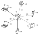
図1は、携帯端末と無線機能を持つ印刷装置との関係を示す図である。図1において、印刷装置101と実線108、109で結ばれた携帯端末102、104は、通常無線を使って接続されているホストである。ここで、携帯端末102はノートPCであり、携帯端末104は携帯電話である。そして、携帯端末103はノートPC、携帯端末105〜107はデジタルカメラ、携帯電話、PDAである。
FIG. 1 is a diagram illustrating a relationship between a mobile terminal and a printing apparatus having a wireless function. In FIG. 1,
図2は、印刷装置にテンポラリーに接続する携帯端末を示す図である。図2において、印刷装置101と破線201〜204で結ばれた携帯端末103、105〜107は、全て必要に応じてテンポラリーに接続され、印刷を行うホストである。
FIG. 2 is a diagram illustrating a portable terminal that is temporarily connected to the printing apparatus. In FIG. 2,
また、携帯端末を印刷装置101に接続し、印刷を行う場合には、図3に示すように、携帯端末から印刷装置101に接続要求を出した時点で印刷装置101から接続に必要なパスワードに相当する『PINコード』の入力が要求される。301は携帯端末でPINコードを入力するための入力画面である。これは、Bluetooth(登録商標)のような無線インターフェースを使用して印刷装置101に接続する場合、無指向性であるため、任意の全ての機器と接続が可能となり、接続制限を設けるために『PINコード』を設定させるものである。この状態で、携帯端末でPINコードを入力しない場合、印刷装置101との接続はできない。
Further, when printing is performed by connecting the mobile terminal to the
図4は、本実施形態における印刷装置の構成の一例を示す機能ブロック図である。図4において、401は無線インターフェース(I/F)、402は有線インターフェース(I/F)である。403は無線/有線機器を利用して接続し、PINコードや印刷設定値をQRコードに変換して表示や印刷を実行する機能モジュールである。404は送られてきたデータに対する制御を行うモジュールである。
FIG. 4 is a functional block diagram illustrating an example of the configuration of the printing apparatus according to the present embodiment. In FIG. 4, 401 is a wireless interface (I / F), and 402 is a wired interface (I / F).
405はCPUであり、無線インターフェース401や有線インターフェース402を介して外部と接続し、要求に応じて、403や404を制御して送信されてきたデータの印刷制御を行い、実際の印刷動作までの全体制御を行う。406は制御を行う上で必要な情報を保存しておくための記憶部である。407はプリンタ制御部であり、CPU405の制御に基づいて実際の印刷動作を行う。
機能モジュール403において、411は無線I/F401、有線I/F402を制御して外部ホストとの接続制御を行う通信制御プログラムである。412はデバイスID(この例ではPINコード)と呼ばれる接続セキュリティを高めるために用いるIDコードの設定、記憶、変更、確認等を行うデバイスID切替部である。413は要求に応じて、デバイスIDの値をQRコードに変換する2次元バーコード生成部である。414は印刷設定値制御部であり、印刷装置の印刷環境の情報を管理、保存し、必要に応じて、その値を出力/入力する。印刷環境情報は、例えば現在装着されている印刷用紙のサイズ、紙質、印刷ヘッドの種類(カラー、モノクロ)、印刷モード(1枚の紙に印刷するページ数)等である。
In the
モジュール404において、421は印刷装置に表示器を実装している場合に画面制御を行う画面表示制御部である。422は本来の印刷装置としての機能や、送付されてきたデータに従って印刷データを構成し、蓄積処理を行う印刷データ解析用記憶部である。
In the
ここで、図3に示す入力画面301にてPINコード入力が正しく行われ、接続できた場合には、図4に示す印刷設定値制御部414が、接続情報(以下「ペアリング情報」と記す)を記憶する。そして、これ以降、同じ携帯端末(ホスト)から接続要求が来た場合、印刷装置101内に記憶した、この情報から再度PINコードの要求を行うこと無く、接続を行うものである。しかしながら、通常、この記憶情報には限界があり、その記憶数は非常に少ない。
If the PIN code is correctly input on the
図5は、印刷装置と携帯端末との間で行われるペアリング情報に含まれる情報の内容を示す図である。図5に示すように、個々のペアリング情報501には、ホスト側の“デバイス名称”、“BDアドレス(Bluetooth(登録商標)のチップ固有アドレス)”、“デバイス識別子”等がある。これらの情報が各デバイス単位にあり、それをまとめた様子を示しているのが502、これらの情報を管理、記憶するものが印刷設定値制御部414である。
FIG. 5 is a diagram illustrating the content of information included in pairing information performed between the printing apparatus and the mobile terminal. As shown in FIG. 5, the
通常、ペアリング情報として印刷装置と接続に使用した『PINコード』は、この中に記憶されない。ここで、PINコードは、印刷装置と接続をするために必要な『接続用のパスワード』であり、1台の印刷装置に、通常1つ用意されるもので、複数は存在しないからである。 Normally, the “PIN code” used for connection with the printing apparatus as pairing information is not stored in this. Here, the PIN code is a “connection password” necessary for connection with the printing apparatus, and is normally prepared for one printing apparatus, and there is no plural.
そこで、複数のホストから1台の印刷装置に一時的であっても接続を行い、印刷動作を行うと、その情報は“ペアリング情報”として印刷設定値制御部414の中に保存される。
Therefore, when a plurality of hosts are temporarily connected to a single printing apparatus and a printing operation is performed, the information is stored in the print setting
図6は、ペアリング情報を管理、保存するテーブルの構成の一例を示す図である。図6に示す例では、記憶できるペアリング情報をN個としているが、大抵の場合、8〜16個であり、それほど多くのペアリング情報は記憶できない。 FIG. 6 is a diagram illustrating an example of a table configuration for managing and storing pairing information. In the example shown in FIG. 6, the number of pairing information that can be stored is N, but in most cases, it is 8 to 16, and so much pairing information cannot be stored.
図6において、602はペアリング情報テーブルである。このテーブルの中で一番上に書かれている“ペアリング情報1”が最も古い(一番最初に記憶したペアリング情報)で、一番下の“ペアリング情報N”が最も新しいペアリング情報である。
In FIG. 6,
従って、新しいペアリング情報603が追加されると、記憶されている最も古い“ペアリング情報1”が601に示すように、古い順に“ペアリング情報テーブル”からあふれ、削除される。このペアリング情報テーブル602に記憶できるペアリング情報の数は、常に最新のN個だけである。
Accordingly, when
そこで、本実施形態では、通常1つのテーブルで管理されている“ペアリング情報”を2つに分けることで、“ペアリング情報”として、従来通り記憶しておくものと、テンポラリーな接続として“ペアリング情報を消してしまうもの”とに分ける。
図7は、本実施形態におけるペアリング情報管理テーブルの構成の一例を示す図である。図7に示すように、ペアリング情報を管理するテーブル701を2つのテーブル702、703に分割する。このテーブル702は、『固定PINコード』に対するペアリング情報を蓄積し、またテーブル703は一時的な接続を目的に発行された『テンポラリーなPINコード』に対するペアリング情報を蓄積する。
Therefore, in the present embodiment, the “pairing information” that is normally managed in one table is divided into two, so that “pairing information” is stored as usual and “temporary connection” is “ "Pairing information is deleted".
FIG. 7 is a diagram showing an example of the configuration of the pairing information management table in the present embodiment. As shown in FIG. 7, a table 701 for managing pairing information is divided into two tables 702 and 703. This table 702 stores pairing information for “fixed PIN code”, and table 703 stores pairing information for “temporary PIN code” issued for the purpose of temporary connection.
従って、印刷装置に1つだけ存在する固定ペアリング情報と、テンポラリーペアリング情報とを別に管理することで、通常固定PINコードで接続しているホスト情報が消えてしまい、接続できない等の問題を解決することができる。 Therefore, by separately managing the fixed pairing information and the temporary pairing information that exist only in the printing apparatus, the host information that is normally connected with the fixed PIN code disappears and the connection cannot be made. Can be solved.
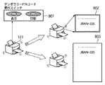
図8は、印刷装置に接続するために必要な“テンポラリーPINコード”の発行手順を説明するための図である。図8に示すスイッチ801は、印刷装置101と接続する上で必要な“テンポラリーPINコード”を発行させるためのスイッチである。具体的には、ユーザの意思によりその情報を用紙803に印刷するか、表示器があれば、画面802に表示するかを切り替えて発行することができる。
FIG. 8 is a diagram for explaining a procedure for issuing a “temporary PIN code” necessary for connection to the printing apparatus. A
図9は、図8に示す“テンポラリーなPINコード”をQRコード等に変換した場合を示す図である。図9において、901はPINコードの提供方式として“QRコード”を使用するか否かを設定するボタンである。QRコード設定ボタン901を“ON”にして、図8に示す“テンポラリーPINコード発行スイッチ”801で“表示”を押下する。これにより、図9に示すように、印刷装置101に表示器が装備されている場合は、その画面802にQRコードで“テンポラリーPINコード”902を表示する。
FIG. 9 is a diagram showing a case where the “temporary PIN code” shown in FIG. 8 is converted into a QR code or the like. In FIG. 9,
但し、“表示”が押下されていても、印刷装置101に表示器が装着されていない場合は、“テンポラリーPINコード”902は自動的に用紙803に印刷される。
However, even if “display” is pressed, if the display device is not attached to the
図10は、本実施形態における印刷装置での接続情報提示処理を示すフローチャートである。テンポラリーPINコードの入手に関しては、このフローチャートに従って行う。まず、ステップS1001において、印刷設定値制御部414が印刷装置101内のテンポラリーPINコードを生成する。次に、ステップS1002で『QRコード設定ボタン901』の設定内容を読み込み、ステップS1003でその設定値を確認する。ここで、QRコードでの提示が設定されている場合にはステップS1004へ進み、まず印刷装置101に表示器が装着されているか否かを確認する。その結果、装備されている場合にはステップS1005へ進み、2次元バーコード生成部413がステップS1001で発行されたPINコードをQRコードに変換する。そして、ステップS1006でQRフラグ(QR Flag)を“1”にセットする。
FIG. 10 is a flowchart showing connection information presentation processing in the printing apparatus according to the present embodiment. The temporary PIN code is obtained according to this flowchart. First, in step S1001, the print setting
また、ステップS1003でQRコードで提示せずに、そのままの文字コードで提示を指定された場合、又はステップS1004で表示器が装備されていない場合にはステップS1007へ進み、QRフラグを“0”にリセットする。
次に、ステップS1008において、『PINコード発行スイッチ801』の値を読み込み、ステップS1009でその値を確認する。ここで、“画面表示”を求められている場合にはステップS1010へ進み、表示器があるか否かを確認する。そして、表示器がある場合(S1010のYES)で、QRフラグが“1”の場合(S1011のYES)ステップS1015へ進み、表示器にQRコードに変換したテンポラリーPINコードを表示する。
Further, if the presentation is designated by the character code as it is without being presented in the QR code in step S1003, or if the display is not equipped in step S1004, the process proceeds to step S1007, and the QR flag is set to “0”. Reset to.
Next, in step S1008, the value of “PIN
また、表示器がある場合(S1010のYES)で、QRフラグが“1”でない場合(S1011のNO)ステップS1016へ進み、画面にテンポラリーなPINコード番号を表示する。 If there is a display (YES in S1010) and the QR flag is not “1” (NO in S1011), the process proceeds to step S1016, and a temporary PIN code number is displayed on the screen.
一方、ステップS1009で、画面表示が求められていない場合はステップS1012へ進み、QRフラグがセットされているか否かを判定する。ここでQRフラグが“1”の場合はステップS1013へ進み、テンポラリーPINコードをQRコードで紙に印刷を行う。また、QRフラグが“1”でない場合はステップS1014へ進み、テンポラリーPINコードを紙に文字として印刷する。 On the other hand, if the screen display is not requested in step S1009, the process proceeds to step S1012 to determine whether the QR flag is set. If the QR flag is “1”, the process advances to step S1013 to print the temporary PIN code on the paper with the QR code. If the QR flag is not “1”, the process advances to step S1014 to print the temporary PIN code as characters on paper.
図10では、ステップS1009で『テンポラリーPINコード発行スイッチ801』の設定内容でPINコードの値を紙に印刷するか、画面表示するか、分けている。しかし、このスイッチ801を読み込まず、『印刷装置に画面表示機能』がある場合には、自動的に画面表示を行っても良い。また、何らかの理由で、画面から情報を読み取れない場合、初めて『テンポラリーPINコード発行スイッチ801』の“印刷”を押下された時点で、印刷に切り替えることも可能である。
In FIG. 10, the PIN code value is printed on paper or displayed on the screen according to the setting contents of “temporary PIN
本実施形態では、固定のPINコードとテンポラリーPINコード発行スイッチの二種類のPINコードを利用し、テンポラリーな接続により、本来維持したいペアリング情報の固定PINコード情報が消えてしまうのを防止する方法を説明した。これは、一時的なテンポラリー接続を行うためのテンポラリーPINコードを発行し、この管理テーブルと、固定PINコード情報を分けて管理し、テンポラリーPINコードは一度使用されたら削除されることを基本としている。 In this embodiment, a method of preventing the fixed PIN code information of the pairing information originally intended to be lost due to temporary connection by using two types of PIN codes, that is, a fixed PIN code and a temporary PIN code issuing switch. Explained. This is based on the fact that a temporary PIN code for temporary connection is issued, the management table and fixed PIN code information are separately managed, and the temporary PIN code is deleted once it is used. .
しかしながら、以下の実施例では、このテンポラリーなPINコードを発行する際に、様々な条件を付加し、更に利用範囲を広げることができる応用例を説明する。 However, in the following embodiment, an application example will be described in which various conditions are added and the range of use can be further expanded when issuing the temporary PIN code.
図11は、本実施形態におけるテンポラリーPINコードを発行する際の応用例を説明するための図である。図11に示すスイッチの中で、1101は図8に示すテンポラリーPINコード発行スイッチ801と同じスイッチである。図11では、接続デバイス設定スイッチ1102、有効印刷枚数設定スイッチ1103、有効時間指定スイッチ1104、有効印刷回数設定スイッチ1105、有効日数指定スイッチ1106がある。これらのスイッチ1102〜1106は、図中の(+)で表示が増え、(―)で表示が減算され、その設定する値が各設定スイッチの向かって左にある7セグに表示される。確認を行い、同時に印刷装置が発行する『テンポラリーPINコード』に付随する付加情報として反映される。
FIG. 11 is a diagram for explaining an application example when issuing a temporary PIN code in the present embodiment. Among the switches shown in FIG. 11, 1101 is the same switch as the temporary PIN
これらの中で接続デバイス設定スイッチ1102が果たす役割は、本実施形態にとって非常に重要である。接続デバイスの種類を事前に明確にすることで、接続する頻度を予測し、初めから他のスイッチと関係なく制限をかけることも可能である。
例えば、接続デバイスが携帯電話の場合、携帯電話の特異性を考え、印刷頻度が低く、一時性が高いことから、初めから使用するテンポラリーPINコードを1度だけの接続&印刷として発行する。逆に、ノートPCの場合、一度接続して印刷を行うと定期的に印刷を繰り替えす可能性が高いことから、テンポラリーPINコードの有効期限を1日(24時間)として発行することも可能である。
Of these, the role played by the connection
For example, when the connection device is a mobile phone, considering the uniqueness of the mobile phone, the printing frequency is low and the temporaryity is high. Therefore, the temporary PIN code used from the beginning is issued as a connection and print only once. Conversely, in the case of a notebook PC, once it is connected and printing is performed, there is a high possibility that printing will be repeated periodically. Therefore, it is possible to issue the temporary PIN code expiration date as one day (24 hours). is there.
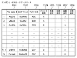
図12は、印刷装置が状況に応じて発行するテンポラリーPINコードのデータベース構造を示す図である。図12に示すように、テンポラリーPINコードは、接続デバイス単位に管理され、固定のPINコード情報と一番大きく違うのは、テンポラリーなPINコードが接続デバイスによって全く違うことである。 FIG. 12 is a diagram showing a database structure of temporary PIN codes issued by the printing apparatus depending on the situation. As shown in FIG. 12, the temporary PIN code is managed for each connected device, and the biggest difference from the fixed PIN code information is that the temporary PIN code is completely different depending on the connected device.
1つのテンポラリーPINコードは、デバイス1つと1対1対応をしていることから、接続時のPINコードで、どのデバイスかを特定し管理することが可能である。 Since one temporary PIN code has a one-to-one correspondence with one device, it is possible to identify and manage which device by the PIN code at the time of connection.
図12に示す一番左の列は、デバイスに割り当てられたシリアル番号を示し、1201のPINコード番号は印刷装置が接続デバイスに割り当てたテンポラリーPINコードを示す。同様に、1204〜1208の各PINコードに設定された条件は、図11に示す設定スイッチで設定された値が記憶されている。
The leftmost column shown in FIG. 12 indicates the serial number assigned to the device, and the
次に、図12に示す接続デバイス設定スイッチ1102で接続デバイスを設定し、各種設定スイッチで印刷枚数、有効時間等を設定した上で、テンポラリーPINコードを発行する処理を説明する。
Next, a process for issuing a temporary PIN code after setting a connection device with the connection
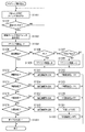
図13は、本実施形態におけるPINコード発行設定処理を示すフローチャートである。まず、ステップS1301において、テンポラリーPINコード発行スイッチ1101の状態を読み込み、ステップS1302で、表示又は印刷が押下されたことを認識するとステップS1303へ進む。ステップS1303では、接続デバイス設定スイッチ1102の状態を読み込む。そして、ステップS1304において、初期設定として『デバイス種類』に携帯電話識別番号である“A”を設定する。
FIG. 13 is a flowchart showing a PIN code issue setting process in the present embodiment. First, in step S1301, the state of the temporary PIN
次に、ステップS1305において、ステップS1303で読み込んだ設定が携帯電話であるか否かを確認し、携帯電話であればステップS1310へ進む。また、携帯電話でない場合はステップS1306へ進み、ノートPCであるか否かを確認し、ノートPCであればステップS1308へ進み、『デバイス種類』にノートPC識別番号である“B”を設定する。また、ノートPCでない場合はステップS1307へ進み、PDA/Palmであるか否かを確認し、PDA/PalmであればステップS1309へ進み、『デバイス種類』にPDA/Palm識別番号である“C”を設定する。 Next, in step S1305, it is confirmed whether or not the setting read in step S1303 is a mobile phone. If it is a mobile phone, the process proceeds to step S1310. If it is not a mobile phone, the process proceeds to step S1306, where it is confirmed whether it is a notebook PC. If it is a notebook PC, the process proceeds to step S1308, and “B” that is a notebook PC identification number is set in “device type”. . If it is not a notebook PC, the process proceeds to step S1307 to check whether it is PDA / Palm. If it is PDA / Palm, the process proceeds to step S1309, and “C”, which is the PDA / Palm identification number in “device type”. Set.
次に、ステップS1310〜S1323において、各PINコードに設定された条件の確認を行う。ステップS1310では、有効印刷枚数が設定されているか否かを確認し、設定されている場合には、ステップS1311でその値を読み込み、ステップS1312で『枚数設定』にその値を保存する。また、ステップS1313では、有効時間が指定されているか否かを判定し、指定されている場合には、ステップS1314でその値を読み込み、ステップS1315で『時間設定』にその値を1分単位で保存する。 Next, in steps S1310 to S1323, the conditions set for each PIN code are confirmed. In step S1310, it is confirmed whether or not the effective number of prints is set. If it is set, the value is read in step S1311 and the value is stored in “number setting” in step S1312. In step S1313, it is determined whether or not an effective time is specified. If it is specified, the value is read in step S1314, and the value is set in “time setting” in step S1315 in units of one minute. save.
また、ステップS1316では、有効印刷回数が設定されているか否かを確認し、設定されている場合には、ステップS1317でその値を読み取り、ステップS1318で『印刷回数設定』にその値を保存する。また、ステップS1319では、有効日数が指定されているか否かを判定し、指定されている場合には、ステップS1320でその値を読み込む。そして、ステップS1321でその値に“24時間×60分”を掛け合わせ、有効時間を分単位に変換し、ステップS1322で『日数設定』に有効時間を保存する。また、何れも設定されていない場合、全ての条件設定値(ここでは、『枚数設定値』、『時間設定』、『印刷回数設定』、『日数設定』)を“1”に設定する。 In step S1316, it is confirmed whether or not the effective number of prints is set. If it is set, the value is read in step S1317, and the value is stored in the “print number setting” in step S1318. . In step S1319, it is determined whether an effective number of days is specified. If specified, the value is read in step S1320. In step S1321, the value is multiplied by “24 hours × 60 minutes” to convert the effective time into minutes, and in step S1322, the effective time is stored in “number of days”. If none is set, all condition setting values (here, “number setting value”, “time setting”, “printing number setting”, “days setting”) are set to “1”.
これにより、図12に示すテーブルの中身を接続するデバイス単位でデータベース化し、これ以降テンポラリーなPINコードで接続要求が発生した場合に、その接続デバイスを特定できる。また、そのPINコード単位に管理された条件に関し印刷管理を行うことができる。 As a result, the contents of the table shown in FIG. 12 are stored in a database for each device to be connected, and when a connection request is issued with a temporary PIN code thereafter, the connected device can be specified. In addition, print management can be performed for the conditions managed in units of the PIN code.
図14は、本実施形態における印刷時のPINコード解析処理を示すフローチャートである。ステップS1401において、接続デバイスから送られてきた情報(BDアドレス、デバイス名等)を解析し、ステップS1402では、テンポラリーPINコード毎に管理される、図12に示すPINコードデータベースを参照する。そして、ステップS1403において、そのデータベースの中に送信されてきたPINコードが存在するか否かを確認する。ここで、テンポラリーPINコードデータベースの中に送信されてきたPINコードが見つからない場合はステップS1401に戻り、印刷装置は接続動作を行わない。 FIG. 14 is a flowchart showing PIN code analysis processing during printing in the present embodiment. In step S1401, information (BD address, device name, etc.) sent from the connected device is analyzed, and in step S1402, the PIN code database shown in FIG. 12 managed for each temporary PIN code is referred to. In step S1403, it is confirmed whether the PIN code transmitted in the database exists. If the PIN code transmitted in the temporary PIN code database is not found here, the process returns to step S1401, and the printing apparatus does not perform the connection operation.
また、ステップS1403でPINコードが存在した場合はステップS1404へ進み、送信されて来たPINコードから、そのPINコードに合わせた印刷条件、例えば印刷可能枚数、有効期限等の項目を読み込む。そして、ステップS1405では、送信されてきたPINコードのデータベースの先頭にポインタを合わせ、そのPINコードに対する情報に枚数設定があるか否かを確認する。ここで、枚数設定があればステップS1411へ進み、今回印刷する印刷枚数分を減算し、ステップS1412で、残枚数が“0”か、マイナスかを判断する。“0”、もしくはマイナスの場合はステップS1413へ進み、以降は同一のPINコードで印刷要求が来た場合に接続及び印刷を行うことはできないので、このテンポラリーPINコードを削除する。また、残枚数がある場合にはステップS1414へ進み、その残枚数をこのPINコードに対応した『枚数設定値』とする。 If a PIN code is present in step S1403, the process proceeds to step S1404, and items such as printing conditions matching the PIN code, such as the number of printable sheets and an expiration date, are read from the transmitted PIN code. In step S1405, the pointer is set to the head of the transmitted PIN code database, and it is confirmed whether or not the number of pieces of information for the PIN code is set. If the number of copies is set, the process advances to step S1411 to subtract the number of prints to be printed this time, and in step S1412, it is determined whether the remaining number is “0” or minus. If “0” or minus, the process proceeds to step S1413. After that, when a print request is received with the same PIN code, connection and printing cannot be performed, so this temporary PIN code is deleted. If there is a remaining number, the process proceeds to step S1414, and the remaining number is set as a “number setting value” corresponding to this PIN code.
また、ステップS1405で枚数設定がなければステップS1406へ進み、印刷回数に関する制限があるか否かを確認する。ここで、印刷回数に関する制限があればステップS1407へ進み、1回分減算し、ステップS1408で、残回数が“0”か確認する。“0”の場合にはステップS1409へ進み、以降このテンポラリーPINコードでの接続を無効とするために、このPINコードをテンポラリーPINコードデータベースから削除する。また、残回数が“0”でなければステップS1410へ進み、その残回数をこのPINコードに対応した『回数設定値』とする。 If it is determined in step S1405 that the number of sheets has not been set, the process advances to step S1406 to check whether there is a restriction on the number of prints. If there is a restriction regarding the number of times of printing, the process proceeds to step S1407, and one time is subtracted. If it is “0”, the process proceeds to step S1409, and this PIN code is deleted from the temporary PIN code database in order to invalidate the connection with this temporary PIN code. If the remaining number is not "0", the process proceeds to step S1410, and the remaining number is set as a "number setting value" corresponding to this PIN code.
図14では、接続時に用いられたPINコードが正しいか否かを切り分け、有効な場合はそのPINコードに付随する設定値の中で、印刷枚数と印刷回数という属性情報の変更処理を説明した。しかしながら、テンポラリーなPINコードに付随する設定値として、時間に関するものもある。 In FIG. 14, it is determined whether or not the PIN code used at the time of connection is correct, and in the case where the PIN code is valid, the change processing of attribute information such as the number of prints and the number of prints is described among the setting values associated with the PIN code. However, there is a time-related setting value associated with the temporary PIN code.
特に、近年の印刷装置においては、FAX機能等、複数の機能を持ち合わせた印刷装置になってきていることから、リアルタイムクロック機能を備えており、使用制限を行う上で『時間制限』も有意義な制限事項となる。 In particular, since recent printing apparatuses have become a printing apparatus having a plurality of functions such as a FAX function, a real-time clock function is provided, and “time restriction” is also significant in restricting use. It becomes a restriction.
図15は、時間に関する有効時間設定及び有効日数設定の処理を示すフローチャートである。これら時間に関する印刷制限は、接続されるタイミングで管理される情報ではなく、発行されたテンポラリーPINコードによる接続の有無とは関係なく、時間経過に関するもので、印刷装置内の時間割り込み処理の中で管理されるものである。図15は通常の印刷装置における時間管理処理に付加されるべき、追加処理に関する処理の流れをまとめたものである。また、この例のタイマー処理は、1分経過毎に起動されるリアルタイマー処理を想定している。 FIG. 15 is a flowchart showing processing for setting an effective time and setting the number of effective days related to time. These printing restrictions related to time are not information managed at the timing of connection, but are related to the passage of time regardless of whether or not there is a connection with the issued temporary PIN code. It is to be managed. FIG. 15 summarizes the flow of processing relating to additional processing that should be added to the time management processing in a normal printing apparatus. In addition, the timer process in this example assumes a real timer process that is activated every minute.
近年の印刷装置には時計機能が備えられており、まず、ステップS1501において、現在の日時を読み込む。次に、ステップS1502において、テンポラリーPINコードデータベースの先頭アドレスをマッピングする。そして、ステップS1503において、設定されたポインタに基づき、テンポラリーPINコードに設定されている印刷条件の中に『時間設定』があるか確認する。ここで、『時間設定(分)』が設定されている場合はステップS1504へ進み、時間設定値から1を減算する。これは、このリアルタイマー処理は、1分単位で起動されることから“テンポラリーPINコード有効時間(分)”を毎回減算する。従って、ステップS1504で、この減算した値が“0”になった場合、有効時間が経過したことになり、ステップS1505で、そのテンポラリーPINコードの情報を全て削除する。 Recent printing apparatuses have a clock function. First, in step S1501, the current date and time are read. In step S1502, the start address of the temporary PIN code database is mapped. In step S1503, based on the set pointer, it is confirmed whether “time setting” is present in the printing conditions set in the temporary PIN code. If “time setting (minutes)” is set, the process advances to step S1504 to subtract 1 from the time setting value. This is because the real-timer process is started in units of 1 minute, so that “temporary PIN code valid time (minutes)” is subtracted every time. Accordingly, when the subtracted value becomes “0” in step S1504, the valid time has elapsed, and in step S1505, all the information of the temporary PIN code is deleted.
次に、ステップS1506において、テンポラリーPINコードデータベースに登録されているPINコード全てのPINコードに対する『時間設定』をチェックしたか否かを確認する。ここで、チェック終了でない場合はステップS1507へ進み、チェックするPINコードのアドレスポインタを次のアドレスに変更し、ステップS1503に戻り、上述の処理を繰り返す。 In step S1506, it is confirmed whether or not “time setting” for all PIN codes registered in the temporary PIN code database is checked. If the check is not finished, the process proceeds to step S1507, the address pointer of the PIN code to be checked is changed to the next address, the process returns to step S1503, and the above processing is repeated.
このように、リアルタイムクロック処理により、テンポラリーPINコードに“時間”に関する制限を加えた場合、ホストとの接続の有無に関係なく、自動的にその有効時間は減算される。そして、有効時間が“0”分になるとPINコードデータベースからPINコードが消される。 As described above, when a restriction relating to “time” is added to the temporary PIN code by the real-time clock processing, the valid time is automatically subtracted regardless of the connection with the host. When the valid time reaches “0”, the PIN code is deleted from the PIN code database.
従って、テンポラリーで発行されるPINコードに有効な動作制限、有効期限等を付加することで、更にテンポラリーPINコードの応用範囲を広げることができる。 Therefore, the application range of the temporary PIN code can be further expanded by adding effective operation restrictions, expiration dates, and the like to the PIN code issued temporarily.
また、発行されたテンポラリーPINコードを使用して接続を行うホストから入手するデバイス名、データを送信する時に使用するデータ転送用プロトコルにより、ホストを見分けPINコードの有効期間を制限しても良い。 Further, the valid period of the PIN code may be limited by distinguishing the host based on the device name obtained from the host that is connected using the issued temporary PIN code and the data transfer protocol used when transmitting data.
図16は、Bluetooth(登録商標)が解析可能なプロファイルでテンポラリーPINコードの有効時間を自動的に切り替える処理を示すフローチャートである。但し、この例では、説明を簡略化するために、『有効期間』を最後の印刷要求があった時間から起算して設定するようになっている。 FIG. 16 is a flowchart showing a process of automatically switching the valid time of a temporary PIN code with a profile that can be analyzed by Bluetooth (registered trademark). However, in this example, in order to simplify the description, the “valid period” is set from the time when the last print request was made.
まず、ステップS1601において、事前に発行したテンポラリーPINコードを使用して接続してきたホストの通信プロファイルを入手する。そして、ステップS1602において、PC系が接続に多く使用しているHCRPの場合はステップS1609へ進み、このテンポラリーPINコードの『有効期間』を60分に設定する。ここで、HCRPはHardcopy Cable Replacement Profileの略である。 First, in step S1601, a communication profile of a connected host is obtained using a temporary PIN code issued in advance. In step S1602, if the PC system uses HCRP that is frequently used for connection, the process proceeds to step S1609, and the “valid period” of this temporary PIN code is set to 60 minutes. Here, HCRP is an abbreviation for Hardcopy Cable Replacement Profile.
また、デジタルカメラやPDA等が使用するBIPの場合はステップS1611へ進み、このテンポラリーPINコードの『有効期間』を30分と設定する。ここで、BIPはBasic Imaging Profileの略である。また、携帯電話が使用するBPPの場合はステップS1610へ進み、このテンポラリーPINコードの『有効期間』を10分と設定する。ここで、BPPはBasic Printing Profileの略である。 If the BIP is used by a digital camera, PDA, or the like, the process advances to step S1611 to set the “valid period” of this temporary PIN code to 30 minutes. Here, BIP is an abbreviation for Basic Imaging Profile. If the BPP is used by the mobile phone, the process proceeds to step S1610, and the “valid period” of the temporary PIN code is set to 10 minutes. Here, BPP is an abbreviation for Basic Printing Profile.
また、何れにも該当しない場合はステップS1605へ進み、“不明なプロファイル”を使った印刷と解析し、このテンポラリーPINコードの『有効期間』を5分と設定する。 If none of these apply, the process proceeds to step S1605, where it is analyzed that “unknown profile” is used for printing, and the “valid period” of this temporary PIN code is set to 5 minutes.
このような処理により、ホストに関するテンポラリーPINコードの有効期間を自動的に設定することができる。その後、ステップS1606において、実際に印刷するデータを受信し、ステップS1607で印刷処理を行う。そして、ステップS1608において、正常に印刷できた場合は、そのまま、この処理を終了し、エラーが発生した場合はステップS1612へ進み、エラー処理を行い、この処理を終了する。 By such processing, the validity period of the temporary PIN code related to the host can be automatically set. Thereafter, in step S1606, data to be actually printed is received, and printing processing is performed in step S1607. In step S1608, if printing is successful, the process is terminated as it is. If an error occurs, the process proceeds to step S1612 to perform error processing, and the process is terminated.
通常、端末と印刷装置を無線機能を使用して接続し、印刷を行うようなシステムでは、接続制限をかけるために、PINコード等デバイス単位に設定される個々の接続用パスワードを使用する。このようなシステムでは、一度正常に接続が行われるとそのペアリング情報が保持され、二度目以降は接続時にPINコード等の入力をしなくても簡単に接続ができるようになっている。しかし、このように保持されるペアリング情報は有限であり、通常制限を越えると古い順にその接続情報が消されていくようになっている。
また、今後普及が見込まれる携帯端末等と印刷装置をテンポラリーに接続し印刷を行うような状況が広がることは必須である。
Usually, in a system in which a terminal and a printing apparatus are connected using a wireless function and printing is performed, an individual connection password set for each device, such as a PIN code, is used to limit connection. In such a system, once a normal connection is made, the pairing information is retained, and from the second time onward, the connection can be easily made without inputting a PIN code or the like. However, the pairing information held in this way is finite, and when the normal limit is exceeded, the connection information is erased from the oldest.
In addition, it is indispensable that a situation where printing is performed by temporarily connecting a portable terminal or the like that is expected to spread in the future to perform printing is essential.
本実施形態によれば、本来、印刷装置と常時接続可能な端末とのペアリング情報を削除することなく、テンポラリー接続、印刷を行うことができる。 According to the present embodiment, it is possible to perform temporary connection and printing without deleting pairing information with a terminal that can be always connected to the printing apparatus.
また、このテンポラリーな接続に関しては、接続に必要なPINコードに、有効期限、印刷枚数の制限等、何らかの条件を付加したPINコードを用いることにより、多種多様な印刷制限を行うことも可能となる。 In addition, regarding this temporary connection, it is possible to perform a wide variety of printing restrictions by using a PIN code to which a certain condition such as an expiration date or a restriction on the number of prints is added as a PIN code necessary for the connection. .
尚、本発明は複数の機器(例えば、ホストコンピュータ,インターフェース機器,リーダ,プリンタなど)から構成されるシステムに適用しても、1つの機器からなる装置(例えば、複写機,ファクシミリ装置など)に適用しても良い。 Even if the present invention is applied to a system composed of a plurality of devices (for example, a host computer, an interface device, a reader, a printer, etc.), it is applied to an apparatus (for example, a copier, a facsimile machine, etc.) composed of a single device. It may be applied.
また、前述した実施形態の機能を実現するソフトウェアのプログラムコードを記録した記録媒体を、システム或いは装置に供給し、そのシステム或いは装置のコンピュータ(CPU若しくはMPU)が記録媒体に格納されたプログラムコードを読出し実行する。これによっても、本発明の目的が達成されることは言うまでもない。 In addition, a recording medium in which a program code of software for realizing the functions of the above-described embodiments is recorded is supplied to the system or apparatus, and the computer (CPU or MPU) of the system or apparatus stores the program code stored in the recording medium. Read and execute. It goes without saying that the object of the present invention can also be achieved by this.
この場合、記録媒体から読出されたプログラムコード自体が前述した実施形態の機能を実現することになり、そのプログラムコードを記憶した記録媒体は本発明を構成することになる。 In this case, the program code itself read from the recording medium realizes the functions of the above-described embodiment, and the recording medium storing the program code constitutes the present invention.
このプログラムコードを供給するための記録媒体として、例えばフレキシブルディスク,ハードディスク,光ディスク,光磁気ディスク,CD−ROM,CD−R,磁気テープ,不揮発性のメモリカード,ROMなどを用いることができる。 As a recording medium for supplying the program code, for example, a flexible disk, a hard disk, an optical disk, a magneto-optical disk, a CD-ROM, a CD-R, a magnetic tape, a nonvolatile memory card, a ROM, or the like can be used.
また、コンピュータが読出したプログラムコードを実行することにより、前述した実施形態の機能が実現されるだけでなく、次の場合も含まれることは言うまでもない。即ち、プログラムコードの指示に基づき、コンピュータ上で稼働しているOS(オペレーティングシステム)などが実際の処理の一部又は全部を行い、その処理により前述した実施形態の機能が実現される場合。 In addition, by executing the program code read by the computer, not only the functions of the above-described embodiments are realized, but also the following cases are included. That is, when the OS (operating system) running on the computer performs part or all of the actual processing based on the instruction of the program code, and the functions of the above-described embodiments are realized by the processing.
更に、記録媒体から読出されたプログラムコードがコンピュータに挿入された機能拡張ボードやコンピュータに接続された機能拡張ユニットに備わるメモリに書込む。その後、そのプログラムコードの指示に基づき、その機能拡張ボードや機能拡張ユニットに備わるCPUなどが実際の処理の一部又は全部を行い、その処理により前述した実施形態の機能が実現される場合も含まれることは言うまでもない。 Further, the program code read from the recording medium is written in a memory provided in a function expansion board inserted into the computer or a function expansion unit connected to the computer. After that, based on the instruction of the program code, the CPU of the function expansion board or function expansion unit performs part or all of the actual processing, and the function of the above-described embodiment is realized by the processing. Needless to say.
101 印刷装置
102 ノートPC
103 ノートPC
104 携帯電話
105 デジタルカメラ
106 携帯電話
107 PDA
301 入力画面
401 無線インターフェース(I/F)
402 有線インターフェース(I/F)
403 機能モジュール
404 モジュール
405 CPU
406 記憶部
407 プリンタ制御部
411 通信制御プログラム
412 デバイスID切替部
413 2次元バーコード生成部
414 印刷設定値制御部
421 画面表示制御部
422 印刷データ解析用記憶部
101
103 notebook PC
104
301
402 Wired interface (I / F)
403
406
Claims (10)
無線接続するデバイスが携帯電話かコンピュータかを設定する設定手段と、
前記設定手段により設定されたデバイスが携帯電話の場合、接続の回数が規定の回数に制限される接続情報を生成し、前記設定手段により設定されたデバイスがコンピュータの場合、接続が可能な期限が制限される接続情報を生成する生成手段と、
前記生成手段により生成された接続情報を表示出力もしくは印刷出力する出力手段と、
前記接続情報に基づいて、前記デバイスと無線接続する接続手段と、
を有することを特徴とする印刷装置。 A printing device,
A setting means for setting whether the wireless connection device is a mobile phone or a computer ;
When the device set by the setting means is a mobile phone, connection information is generated so that the number of connections is limited to a prescribed number. When the device set by the setting means is a computer, there is a time limit for connection. Generating means for generating connection information to be restricted;
Output means for displaying or printing out the connection information generated by the generating means;
Based on the connection information, connection means for wireless connection with the device;
A printing apparatus comprising:
無線接続するデバイスが携帯電話かコンピュータかを設定する設定工程と、
前記設定工程において設定されたデバイスが携帯電話の場合、接続の回数が規定の回数に制限される接続情報を生成し、前記設定工程において設定されたデバイスがコンピュータの場合、接続が可能な期限が制限される接続情報を生成する生成工程と、
前記生成工程において生成された接続情報を表示出力もしくは印刷出力する出力工程と、
前記接続情報に基づいて、前記デバイスと無線接続する接続工程と、
を有することを特徴とする印刷装置の接続方法。 A method of connecting a printing device,
A setting process for setting whether a wireless connection device is a mobile phone or a computer ;
When the device set in the setting step is a mobile phone, connection information is generated in which the number of connections is limited to a prescribed number. When the device set in the setting step is a computer, there is a time limit for connection. A generation process for generating limited connection information;
An output step for displaying or printing out the connection information generated in the generation step;
A connection step of wirelessly connecting to the device based on the connection information;
A method of connecting a printing apparatus, comprising:
Priority Applications (2)
| Application Number | Priority Date | Filing Date | Title |
|---|---|---|---|
| JP2006048974A JP4812089B2 (en) | 2006-02-24 | 2006-02-24 | Printing apparatus and connection method thereof |
| US11/677,226 US8289890B2 (en) | 2006-02-24 | 2007-02-21 | Printing apparatus and method of connecting same |
Applications Claiming Priority (1)
| Application Number | Priority Date | Filing Date | Title |
|---|---|---|---|
| JP2006048974A JP4812089B2 (en) | 2006-02-24 | 2006-02-24 | Printing apparatus and connection method thereof |
Publications (3)
| Publication Number | Publication Date |
|---|---|
| JP2007228419A JP2007228419A (en) | 2007-09-06 |
| JP2007228419A5 JP2007228419A5 (en) | 2009-04-09 |
| JP4812089B2 true JP4812089B2 (en) | 2011-11-09 |
Family
ID=38443860
Family Applications (1)
| Application Number | Title | Priority Date | Filing Date |
|---|---|---|---|
| JP2006048974A Expired - Fee Related JP4812089B2 (en) | 2006-02-24 | 2006-02-24 | Printing apparatus and connection method thereof |
Country Status (2)
| Country | Link |
|---|---|
| US (1) | US8289890B2 (en) |
| JP (1) | JP4812089B2 (en) |
Families Citing this family (39)
| Publication number | Priority date | Publication date | Assignee | Title |
|---|---|---|---|---|
| KR20080078368A (en) * | 2007-02-23 | 2008-08-27 | 삼성전자주식회사 | Method of wireless communication for changing wireless device to wireless communicate after user's confirmation and av apparatus thereof |
| JP4692580B2 (en) | 2008-06-06 | 2011-06-01 | コニカミノルタビジネステクノロジーズ株式会社 | Image processing apparatus, image processing method, and image processing program |
| US10032239B2 (en) | 2010-06-10 | 2018-07-24 | United Parcel Service Of America, Inc. | Enhanced payments for shipping |
| US10033718B2 (en) * | 2011-01-05 | 2018-07-24 | Lenovo (Singapore) Pte. Ltd. | Pairing of base and detachable device |
| US20120198531A1 (en) * | 2011-01-31 | 2012-08-02 | Microsoft Corporation | Multi-device session pairing using a visual tag |
| US20130031261A1 (en) * | 2011-07-29 | 2013-01-31 | Bradley Neal Suggs | Pairing a device based on a visual code |
| US8819428B2 (en) * | 2011-10-21 | 2014-08-26 | Ebay Inc. | Point of sale (POS) personal identification number (PIN) security |
| JP5889003B2 (en) * | 2012-01-26 | 2016-03-22 | 株式会社Pfu | Image acquisition device |
| JP5950691B2 (en) * | 2012-02-09 | 2016-07-13 | シャープ株式会社 | Information processing system, information processing apparatus, and communication connection method |
| JP6016481B2 (en) * | 2012-07-02 | 2016-10-26 | キヤノン株式会社 | Image forming apparatus, wireless setting method, and program |
| KR20140052690A (en) * | 2012-10-25 | 2014-05-07 | 삼성전자주식회사 | Electronic apparatus and control method of system |
| JP6044338B2 (en) * | 2012-12-28 | 2016-12-14 | キヤノンマーケティングジャパン株式会社 | Image forming apparatus, portable terminal, information processing system, and method and program thereof |
| JP6157117B2 (en) * | 2012-12-31 | 2017-07-05 | 株式会社コシダカホールディングス | Network karaoke system |
| TWI569618B (en) * | 2014-10-31 | 2017-02-01 | 黃能富 | Communication method of hiding privacy and system thereof |
| WO2016088310A1 (en) * | 2014-12-04 | 2016-06-09 | セイコーエプソン株式会社 | Printing device, printing device control method, and storage medium |
| JP6488865B2 (en) | 2014-12-04 | 2019-03-27 | セイコーエプソン株式会社 | Printing apparatus, printing apparatus control method, and storage medium |
| JP2016134007A (en) * | 2015-01-20 | 2016-07-25 | 株式会社リコー | Information processing system, information processing apparatus, device, information processing method, and program |
| US20160257198A1 (en) | 2015-03-02 | 2016-09-08 | Ford Global Technologies, Inc. | In-vehicle component user interface |
| US9747740B2 (en) | 2015-03-02 | 2017-08-29 | Ford Global Technologies, Llc | Simultaneous button press secure keypad code entry |
| JP6576129B2 (en) * | 2015-07-06 | 2019-09-18 | キヤノン株式会社 | COMMUNICATION DEVICE, COMMUNICATION METHOD, AND PROGRAM |
| US9914418B2 (en) | 2015-09-01 | 2018-03-13 | Ford Global Technologies, Llc | In-vehicle control location |
| US9967717B2 (en) | 2015-09-01 | 2018-05-08 | Ford Global Technologies, Llc | Efficient tracking of personal device locations |
| US9860710B2 (en) | 2015-09-08 | 2018-01-02 | Ford Global Technologies, Llc | Symmetrical reference personal device location tracking |
| US9744852B2 (en) | 2015-09-10 | 2017-08-29 | Ford Global Technologies, Llc | Integration of add-on interior modules into driver user interface |
| EP3144798B1 (en) * | 2015-09-18 | 2020-12-16 | Canon Kabushiki Kaisha | Image processing apparatus, method of controlling the same, and storage medium |
| US20170149946A1 (en) * | 2015-11-23 | 2017-05-25 | Ford Global Technologies, Llc | Simplified connection to and disconnection from vehicle computing systems |
| US10046637B2 (en) | 2015-12-11 | 2018-08-14 | Ford Global Technologies, Llc | In-vehicle component control user interface |
| KR101704486B1 (en) * | 2015-12-29 | 2017-02-08 | 현대자동차주식회사 | Apparatus and method of controlling outgoing calls in vehicle |
| US9819832B2 (en) | 2015-12-29 | 2017-11-14 | Kabushiki Kaisha Toshiba | Image forming apparatus and authentication method |
| US10082877B2 (en) | 2016-03-15 | 2018-09-25 | Ford Global Technologies, Llc | Orientation-independent air gesture detection service for in-vehicle environments |
| US9914415B2 (en) | 2016-04-25 | 2018-03-13 | Ford Global Technologies, Llc | Connectionless communication with interior vehicle components |
| JP6784155B2 (en) | 2016-11-28 | 2020-11-11 | セイコーエプソン株式会社 | Wireless communication devices, wireless communication terminals, wireless communication systems, and wireless communication methods |
| JP6822180B2 (en) | 2017-02-02 | 2021-01-27 | セイコーエプソン株式会社 | Printing device, control method of printing device, and communication system |
| JP6866209B2 (en) * | 2017-03-31 | 2021-04-28 | キヤノン株式会社 | Information processing device, control method, program |
| JP6667476B2 (en) | 2017-06-30 | 2020-03-18 | キヤノン株式会社 | Communication device, control method, and program |
| JP6580090B2 (en) | 2017-06-30 | 2019-09-25 | キヤノン株式会社 | COMMUNICATION METHOD, COMMUNICATION DEVICE, AND PROGRAM |
| JP6628830B2 (en) * | 2018-04-03 | 2020-01-15 | キヤノン株式会社 | Information processing apparatus, image processing apparatus, control method, and computer program |
| JP7129233B2 (en) * | 2018-06-14 | 2022-09-01 | キヤノン株式会社 | Information processing device, control method, program |
| JP7155358B2 (en) * | 2019-12-03 | 2022-10-18 | キヤノン株式会社 | Program and information processing device |
Family Cites Families (10)
| Publication number | Priority date | Publication date | Assignee | Title |
|---|---|---|---|---|
| US6343083B1 (en) * | 1998-04-09 | 2002-01-29 | Alcatel Usa Sourcing, L.P. | Method and apparatus for supporting a connectionless communication protocol over an ATM network |
| US6886095B1 (en) * | 1999-05-21 | 2005-04-26 | International Business Machines Corporation | Method and apparatus for efficiently initializing secure communications among wireless devices |
| JP3544918B2 (en) * | 2000-04-28 | 2004-07-21 | 株式会社東芝 | Wireless communication device and user authentication method |
| US7245602B2 (en) * | 2000-11-22 | 2007-07-17 | Telefonaktiebolaget Lm Ericsson (Publ) | System and method for anonymous Bluetooth devices |
| JP2002163584A (en) * | 2000-11-24 | 2002-06-07 | Fujitsu Ltd | Method for card settlement using portable information terminal and its system |
| US20020130834A1 (en) * | 2001-03-16 | 2002-09-19 | Emsquare Research, Inc. | System and method for universal control of devices |
| JP3761505B2 (en) * | 2002-03-04 | 2006-03-29 | 株式会社東芝 | COMMUNICATION SYSTEM, RADIO COMMUNICATION TERMINAL, AND RADIO COMMUNICATION DEVICE |
| JP4455076B2 (en) * | 2004-01-28 | 2010-04-21 | キヤノン株式会社 | Wireless communication apparatus authentication method, wireless communication apparatus, computer program, and computer-readable recording medium |
| JP2006001063A (en) * | 2004-06-16 | 2006-01-05 | Fuji Photo Film Co Ltd | Direct print system |
| JP4157079B2 (en) * | 2004-08-04 | 2008-09-24 | インターナショナル・ビジネス・マシーンズ・コーポレーション | Information processing system, communication method, program, recording medium, and access relay service system |
-
2006
- 2006-02-24 JP JP2006048974A patent/JP4812089B2/en not_active Expired - Fee Related
-
2007
- 2007-02-21 US US11/677,226 patent/US8289890B2/en not_active Expired - Fee Related
Also Published As
| Publication number | Publication date |
|---|---|
| US8289890B2 (en) | 2012-10-16 |
| US20070201389A1 (en) | 2007-08-30 |
| JP2007228419A (en) | 2007-09-06 |
Similar Documents
| Publication | Publication Date | Title |
|---|---|---|
| JP4812089B2 (en) | Printing apparatus and connection method thereof | |
| US9218148B2 (en) | Information processing apparatus, storage medium, and control method | |
| JP5173563B2 (en) | License management apparatus and method | |
| US7982887B2 (en) | Image forming device, image forming method, image processing device, and computer readable storage medium storing image forming program | |
| JP4881915B2 (en) | Printing system, print management server, control method therefor, and program | |
| US20060139685A1 (en) | Information-processing apparatus, image-processing method, and computer program | |
| US10120623B2 (en) | Image forming apparatus enabling charging management, control method therefor, and storage medium storing control program therefor | |
| JP2016181287A (en) | Semiconductor storage device | |
| JP2008312123A (en) | Image processor, image processing system, and method of controlling image processor and program therefor | |
| CN104426587A (en) | Wireless communication device and wireless communication method | |
| JP6045217B2 (en) | Image forming apparatus, control method thereof, and program | |
| JP2007272458A (en) | Information processor, information processing system, and information processing method | |
| JP2008071092A (en) | Server device, client device, server base computing system and program | |
| JP6557969B2 (en) | Image forming apparatus, control method thereof, and program | |
| JP2006228062A (en) | Printing system, printing method and program thereof | |
| JP2008009734A (en) | Terminal device and program | |
| JP2006240152A (en) | Print system and its printing method | |
| JP2017081054A (en) | Image formation device, image formation system, control method therefor, and program | |
| JP2011118734A (en) | System, method and device for monitoring printed matter, control method, program and recording medium | |
| JP5664037B2 (en) | Printing system, image processing apparatus, control method, and program thereof | |
| JP5262808B2 (en) | Printing system and printing apparatus | |
| JP5030178B2 (en) | Printing system, information processing apparatus, printing apparatus, printing method, control method, and program | |
| JP2020009062A (en) | Printing system, printing device, and program | |
| CN103959889A (en) | Recording medium and control method thereof | |
| JP6680153B2 (en) | Printing system, mobile terminal device and printing device |
Legal Events
| Date | Code | Title | Description |
|---|---|---|---|
| A521 | Written amendment |
Free format text: JAPANESE INTERMEDIATE CODE: A523 Effective date: 20090220 |
|
| A621 | Written request for application examination |
Free format text: JAPANESE INTERMEDIATE CODE: A621 Effective date: 20090220 |
|
| A977 | Report on retrieval |
Free format text: JAPANESE INTERMEDIATE CODE: A971007 Effective date: 20101220 |
|
| A131 | Notification of reasons for refusal |
Free format text: JAPANESE INTERMEDIATE CODE: A131 Effective date: 20101224 |
|
| A521 | Written amendment |
Free format text: JAPANESE INTERMEDIATE CODE: A523 Effective date: 20110218 |
|
| A131 | Notification of reasons for refusal |
Free format text: JAPANESE INTERMEDIATE CODE: A131 Effective date: 20110408 |
|
| A521 | Written amendment |
Free format text: JAPANESE INTERMEDIATE CODE: A523 Effective date: 20110606 |
|
| TRDD | Decision of grant or rejection written | ||
| A01 | Written decision to grant a patent or to grant a registration (utility model) |
Free format text: JAPANESE INTERMEDIATE CODE: A01 Effective date: 20110819 |
|
| A01 | Written decision to grant a patent or to grant a registration (utility model) |
Free format text: JAPANESE INTERMEDIATE CODE: A01 |
|
| A61 | First payment of annual fees (during grant procedure) |
Free format text: JAPANESE INTERMEDIATE CODE: A61 Effective date: 20110822 |
|
| FPAY | Renewal fee payment (event date is renewal date of database) |
Free format text: PAYMENT UNTIL: 20140902 Year of fee payment: 3 |
|
| LAPS | Cancellation because of no payment of annual fees |