JP4810257B2 - Image forming apparatus - Google Patents
Image forming apparatus Download PDFInfo
- Publication number
- JP4810257B2 JP4810257B2 JP2006056778A JP2006056778A JP4810257B2 JP 4810257 B2 JP4810257 B2 JP 4810257B2 JP 2006056778 A JP2006056778 A JP 2006056778A JP 2006056778 A JP2006056778 A JP 2006056778A JP 4810257 B2 JP4810257 B2 JP 4810257B2
- Authority
- JP
- Japan
- Prior art keywords
- recording material
- image forming
- forming apparatus
- light
- paper
- Prior art date
- Legal status (The legal status is an assumption and is not a legal conclusion. Google has not performed a legal analysis and makes no representation as to the accuracy of the status listed.)
- Active
Links
- 239000000463 material Substances 0.000 claims description 167
- 230000003287 optical effect Effects 0.000 claims description 12
- 230000001678 irradiating effect Effects 0.000 claims description 3
- 239000000123 paper Substances 0.000 description 89
- 238000004364 calculation method Methods 0.000 description 18
- 238000012546 transfer Methods 0.000 description 14
- 239000000835 fiber Substances 0.000 description 13
- 238000012545 processing Methods 0.000 description 12
- 238000000034 method Methods 0.000 description 7
- 238000010586 diagram Methods 0.000 description 4
- 238000006243 chemical reaction Methods 0.000 description 3
- 239000003086 colorant Substances 0.000 description 3
- 230000006835 compression Effects 0.000 description 3
- 238000007906 compression Methods 0.000 description 3
- 230000005540 biological transmission Effects 0.000 description 2
- 238000001514 detection method Methods 0.000 description 2
- 238000012850 discrimination method Methods 0.000 description 2
- 238000010438 heat treatment Methods 0.000 description 2
- 238000009434 installation Methods 0.000 description 2
- 230000001788 irregular Effects 0.000 description 2
- 239000000969 carrier Substances 0.000 description 1
- 238000011161 development Methods 0.000 description 1
- 238000003384 imaging method Methods 0.000 description 1
- 238000005259 measurement Methods 0.000 description 1
- 238000005070 sampling Methods 0.000 description 1
- 230000035945 sensitivity Effects 0.000 description 1
- 238000002834 transmittance Methods 0.000 description 1
Images


Description
本発明は、複写機、レーザープリンタ等の画像形成装置に関するものである。 The present invention relates to an image forming apparatus such as a copying machine or a laser printer.
複写機、レーザープリンタ等の画像形成装置は、潜像担持体と、現像装置と、転写手段と、定着装置とを具えている。潜像担持体は潜像を担持する。現像装置は、潜像担持体に現像剤を付与することにより上記潜像を現像剤像として可視化する。転写手段は、所定方向に搬送される記録材に該現像装置による該現像剤像を転写する。定着装置は、転写手段によって上記現像剤像の転写を受けた上記記録材を所定の定着処理条件にて加熱及び加圧することにより上記現像剤像を上記記録材に定着させる。 An image forming apparatus such as a copying machine or a laser printer includes a latent image carrier, a developing device, a transfer unit, and a fixing device. The latent image carrier carries a latent image. The developing device visualizes the latent image as a developer image by applying a developer to the latent image carrier. The transfer unit transfers the developer image by the developing device to a recording material conveyed in a predetermined direction. The fixing device fixes the developer image on the recording material by heating and pressurizing the recording material, which has received the transfer of the developer image by a transfer unit, under predetermined fixing processing conditions.
従来、かかる画像形成装置においては、例えば、画像形成装置本体に設けられた操作パネル等に記録材たる記録材のサイズや種類(以下、紙種ともいう)がユーザーによって設定される。さらに、その設定に応じて定着処理条件(例えば、定着温度や定着装置を通過する記録材の搬送速度)を設定するよう制御する。 Conventionally, in such an image forming apparatus, for example, the size and type (hereinafter also referred to as paper type) of a recording material as a recording material is set by a user on an operation panel or the like provided in the main body of the image forming apparatus. Further, control is performed so as to set the fixing processing conditions (for example, the fixing temperature and the conveyance speed of the recording material passing through the fixing device) according to the setting.
あるいは、画像形成装置内部に記録材を判別するセンサを用いて、記録材の種類によって現像条件、転写条件、搬送条件あるいは定着条件を可変制御する。 Alternatively, a development condition, a transfer condition, a conveyance condition, or a fixing condition are variably controlled according to the type of the recording material by using a sensor for determining the recording material in the image forming apparatus.
特に、後者の画像形成装置内部においては、例えば特許文献1において提案されているように、反射型光学センサが設置される場合がある。即ち、この反射型光学センサは、発光素子と、発光素子から発射された光が検出面により反射され、その反射光を受光する位置に設置された第一の受光センサと、前記受光センサと異なる角度で設置された第二の受光センサとを備えている。このようなセンサでは、光沢度の高いグロスフィルムと、光沢度の低い普通紙とを判別することができる。 In particular, in the latter image forming apparatus, for example, as proposed in Patent Document 1, a reflective optical sensor may be installed. That is, the reflective optical sensor is different from the light receiving element and the first light receiving sensor installed at a position where the light emitted from the light emitting element is reflected by the detection surface and receives the reflected light. And a second light receiving sensor installed at an angle. Such a sensor can discriminate between a gloss film having a high gloss level and plain paper having a low gloss level.
さらに、特許文献2で提案されているように前記記録紙を判別するセンサに対向する位置に発光源を設け、透過光を検出することにより、透過光による記録紙の厚さを判別する装置が提案されている。 Further, as proposed in Patent Document 2, there is provided an apparatus for determining a thickness of a recording paper by transmitted light by providing a light emitting source at a position facing the sensor for determining the recording paper and detecting transmitted light. Proposed.
その他にも、特許文献3で提案されているように記録材の表面画像をCCDセンサあるいはCMOSセンサによって撮像しその光の大小関係から記録材の粗度を検出する方法や、記録材端部に出来る影の長さから記録材の厚みを検出する方法が提案されている。 In addition, as proposed in Patent Document 3, a surface image of a recording material is picked up by a CCD sensor or a CMOS sensor, and the roughness of the recording material is detected from the magnitude relationship of the light. A method for detecting the thickness of a recording material from the length of a shadow that can be produced has been proposed.
しかしながら、上述の従来の画像形成装置では、以下のような課題を有している。
従来の判別方式では、記録材が給紙される給紙口に関わらず、全記録材に対して1つの判別テーブルしか有していないため、市場にある多くの記録材の種類を正確に検出し、その全ての種類の記録材において適正な印刷条件を設定することは非常に困難である。
However, the above-described conventional image forming apparatus has the following problems.
The conventional discrimination method has only one discrimination table for all recording materials regardless of the paper feed port to which the recording material is fed, so it can accurately detect many types of recording materials on the market. However, it is very difficult to set appropriate printing conditions for all types of recording materials.
そこで本発明では、正確な記録材判別情報に基づく適正な印字条件を設定可能な記録材を増やすことができる画像形成装置を提供することを目的とする。 Therefore, an object of the present invention is to provide an image forming apparatus capable of increasing the number of recording materials that can set appropriate printing conditions based on accurate recording material discrimination information.
本発明は、上述した課題を解決することを目的としてなされたもので、係る目的を達成するため、複数の給紙口から記録材を各々供給する給紙手段と、前記給紙手段から供給された記録材の搬送路上で記録材の表面に光を照射した結果得られる光学的な情報に基づいて当該記録材の種類を判別する記録材判別手段と、前記記録材判別手段の判別結果に基づいて画像形成条件を決定する制御手段とを具え、前記記録材判別手段は、前記各給紙口に応じた個別の記録材を判別する情報を有し、供給された記録材の給紙口に対応した記録材を判別する情報を用いて前記判別を実行することを特徴とする。
The present invention has been made for the purpose of solving the above-described problems, and in order to achieve such an object, a sheet feeding unit that supplies recording materials from a plurality of sheet feeding ports, and a sheet feeding unit that is supplied from the sheet feeding unit. a recording medium discrimination means for discriminating the type of the recording material based on the surface on the optical information obtained as a result of irradiating the optical recording material in the conveyance path of the recording material was, based on the discrimination result of said recording material determining means and control means for determining an image forming condition Te, the recording material determining means includes information for determining the individual of the recording material corresponding to the respective feed port, feeding port of the supplied recording material The determination is performed using information for determining a corresponding recording material.
本発明によれば、膨大な数の記録材の判別を正確に行うことが可能であり、記録材に応じた適切な印刷条件の設定が行える。 According to the present invention, it is possible to accurately determine a huge number of recording materials, and it is possible to set appropriate printing conditions according to the recording materials.
(実施例1)
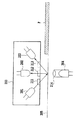
図1に本発明の第一の実施例にかかる記録材判別センサ200の構成を示す。記録材判別センサ200は、図1に示すように、第1の照射手段であるLED201、第2の照射手段であるLED204、第1の読取手段であるフォトトランジスタ203、第2の読取手段であるフォトトランジスタ202を有している。
(Example 1)
FIG. 1 shows a configuration of a recording
LED201を光源とする光は、スリット211を介して記録材搬送ガイド205上の記録材Pの表面に対し照射される。また、記録材搬送ガイド205は、本実施例では記録材の裏面側から光を照射するための窓を設けてある。記録材Pからの反射光は、スリット212、213を介し集光されてフォトトランジスタ202、203に受光される。これらの受光信号に基づいて記録材Pの光沢度を検出する。
Light having the
LED204を光源とする光は、光を集光させるためにある集光ガイド214を通って記録材Pの裏面へ照射される。記録材Pからの透過光は、スリット212、213を介してフォトトランジスタ202、203に受光される。これらの受光信号に基づいて記録材Pからの透過光量を検出する。本実施例では、LED201は、LED光が記録材P表面に対し図1に示すように所定の角度をもって斜めより照射されるよう配置されている。また、LED204はLED光が記録材P裏面に対し、図1のようにフォトトランジスタ202の真下の位置から照射されるように配置されている。
Light using the
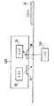
次に、図2を用いてセンサ制御部の内部構成を示すブロック図について説明する。発光素子駆動部305は、発光部301、302を構成するLED201、204を駆動し、メイン制御部306は発光素子駆動部305を制御する。信号処理部307は、受光部303,304を構成するフォトトランジスタ202,203からの出力値を16bitの分解能でA/D変換を行い、フォトトランジスタ202,203の出力値を演算する。例えば、出力値の演算は、記録材の光沢度を示す(正反射出力/乱反射出力)値、および記録材の光透過性を示す正透過出力値(フォトトランジスタ202の出力)を求める。
Next, a block diagram showing the internal configuration of the sensor control unit will be described with reference to FIG. The light emitting
また、比較部308は、信号処理部307で得られた演算結果とあらかじめメモリ309に格納されている設定値との間の比較演算を行い、記録材を判別する。メモリ309は、EEPROMのような不揮発メモリであり、記録材判別のための設定値が格納されている。この設定値の詳細については後述するが、工場出荷時等に実際に各種の記録材を各給紙口から供給して記録材判別センサ200によって測定した値を参照して設定値を求めることができる。
In addition, the
また、メモリ309には、発光部301を構成するLED201に対しては、2種類以上の異なる発光光量値が格納されている。また、発光部302を構成するLED204に対しては、1種類の発光光量値が格納されている。例えば、工場出荷時などに基準紙を用いてLED201からの光を照射した基準紙からの正反射光量、乱反射光量を検出しその結果から受光部303,304それぞれに対する発光光量値をメモリ309に格納する。フォトトランジスタ202,203それぞれに対して発光光量値を設定する理由として、受光素子の感度ばらつきを、発光光量を変えることでキャンセルすることができるからである。
In addition, the
なお、CPUは、メモリ309に格納されている発光光量値を読み出し、その値に応じた電流値でLED201、LED204を駆動する。発光光量値から電流値への変換は予めメモリ309に記憶された変換テーブル(不図示)を用いる。
The CPU reads the light emission amount value stored in the
また、LED204も同様に工場出荷時などに上記と同様の基準紙を用いて基準紙からの正透過光量をフォトトランジスタ202によって検出し、その結果から求めた発光光量値をメモリ309に格納する。
Similarly, the
このセンサ制御部を構成するメイン制御部は、CPUと、このCPUの制御手順を格納したROMと、CPUの作業領域を提供するRAMとを有する。このメイン制御部によって、記録材判別センサを制御して、記録材を判別する。なお、このメイン制御部は、図3の画像形成装置全体を制御する制御手段によって構成することもできる。 The main control unit that constitutes the sensor control unit includes a CPU, a ROM that stores a control procedure of the CPU, and a RAM that provides a work area for the CPU. The main control unit controls the recording material discrimination sensor to discriminate the recording material. The main control unit can also be configured by a control unit that controls the entire image forming apparatus of FIG.
図3は本実施例にかかる画像形成装置を示す。 FIG. 3 shows an image forming apparatus according to this embodiment.
画像形成装置101は、図3に示すような構成を有している。即ち、用紙トレイ102、給紙ローラ103、転写ベルト駆動ローラ104、転写ベルト105、潜像担持体たる感光ドラム106〜109である。さらに、転写手段たる転写ローラ110〜113、各色トナーのカートリッジ114〜117、光学ユニット118〜121、定着装置たる定着ユニット122等を有している。
The
画像形成装置101にあっては、電子写真プロセスを用い記録材たる記録材の上にイエロー、マゼンタ、シアン、ブラックの各色のトナー画像を重ねて転写する。そして、定着ユニット122の定着ローラ(図示せず)によって上記記録材を所定温度で加熱すると共に加圧することにより上記トナー画像を上記記録材に定着させる。
In the
各色の光学ユニット118〜121は、各感光ドラム106〜109の表面を画像情報に応じたレーザビームによって露光走査して画像情報に対応する潜像を形成するよう構成されている。また各色の光学ユニット118〜121における、これら一連の画像形成動作は搬送される記録材上の予め決まった位置から画像が転写されるよう同期をとって走査制御される。各感光ドラム106〜109の表面に形成された潜像は、カートリッジ114〜117に備えられた現像装置(図示せず)によって各色の現像剤たるトナーによってトナー画像として可視化される。
The
また、画像形成装置101は、記録材を給紙及び搬送する給紙モータ(図示せず)と、転写ベルト駆動ローラ104を駆動する転写ベルト駆動モータ(図示せず)とを備えている。さらに、画像形成装置101は、各色感光ドラム106〜109及び転写ローラ110〜113を駆動する感光ドラム駆動モータ(図示せず)と、上記定着ローラを駆動する定着駆動モータ(図示せず)とを備えている。
The
また、画像形成装置101は、カセットトレイ102(以下CSTと記す)、マルチトレイ(以下MPTと記す)123とを備え、更に、複数の給紙可能なオプショントレイ(図示せず)を備えることができる。
Further, the
更に、画像形成装置101は、複数の給紙口から給紙され搬送されることにより合流する搬送路上に1つの記録材判別センサ200と、搬送路面を介して記録材判別センサの反対側にLED204を備えている。記録材判別センサ200は、カセット給紙ローラ103やマルチ給紙ローラ124によってCST102やMPT123から給紙され搬送される記録材の表面に光を照射させて、その時の正反射光量と乱反射光量を検出する。また、記録材判別センサ200は、搬送させる記録材の裏面から光を照射させ、記録材の透過光量を検出する。
Further, the
次に、本実施例のメイン制御部306における制御フローを説明する。ユーザーによりCST102やMPT123やオプショントレイ(図示せず、以下OPTと記す)に記録材がセットされた後、プリント開始コマンドをパーソナルコンピュータなどの外部装置から受信するとプリントを開始する。記録材判別センサ200の位置まで記録材が到達したら、図2に示すメイン制御部によって記録材判別センサ200内のLED201をメモリ309に格納された発光光量値で発光させ、フォトトランジスタ202,203で反射光を受光する。LED204はLED201が消灯してからメモリ309に格納された発光光量値で発光させ、フォトトランジスタ202で記録材の透過光を受光する。LED204が消灯後、給紙口に対応した個別の判別テーブルに基づいて、検知結果の値と比較演算を行う。その演算結果から、記録材の種類が確定する。
Next, a control flow in the
次に、メイン制御部306において給紙口に応じた個別の記録材判別テーブル(図5または6)を選択して用いる理由について述べる。
Next, the reason for selecting and using the individual recording material discrimination table (FIG. 5 or 6) corresponding to the sheet feeding port in the
図4に示すように、従来までの判別方法では、様々な給紙口から給紙される記録材を初期のしきい値 a, bからなる1種類の判別テーブルで分類しようとしていた。1種類の判別テーブルでは、記録材によっては、閾値をオーバーラップしてしまう紙種が存在する。その理由としては、給紙口によって記録材判別センサが記録紙の表面或いは裏面を測定することや、給紙口により記録材判別センサと記録紙との間の距離が異なること等が考えられる。具体的には、図10に示すように、給紙される給紙口によって、記録紙と判別センサとの距離が異なってくる。 As shown in FIG. 4, in the conventional discrimination method, recording materials fed from various paper feed ports are to be classified by one type of discrimination table including initial threshold values a and b. In one type of discrimination table, depending on the recording material, there is a paper type that overlaps the threshold value. The reason may be that the recording material discrimination sensor measures the front or back surface of the recording paper by the paper feed port, or that the distance between the recording material discrimination sensor and the recording paper differs by the paper feed port. Specifically, as shown in FIG. 10, the distance between the recording sheet and the discrimination sensor varies depending on the sheet feeding port to which the sheet is fed.
以上のように、1種類の判別テーブルでは、記録材に最適なモードで印字することができない。そこで、このような不具合を減少させるために、給紙口に応じた個別の判別テーブルを用いる。図5に、CST102から給紙された記録紙に適用する判別テーブルを示す。この判別テーブルでは、図4に示した初期のしきい値a, bをCST102に対応したしきい値a', b'に最適化を行っている。図5に示す判別テーブルでは、図4に示す従来の判別テーブルでは誤って判別していた普通紙を正しく判別できている。図6に、MPT123から給紙された記録紙に適用する判別テーブルを示す。この判別テーブルでは、図4に示した初期のしきい値bをMPT123に対応したしきい値b”に最適化を行っている。CST102の場合と同様に、MPT123においても、誤って判別していた厚紙を正しく判別できていることがわかる。
As described above, one type of discrimination table cannot be printed in a mode optimal for a recording material. Therefore, in order to reduce such a problem, an individual determination table corresponding to the sheet feeding port is used. FIG. 5 shows a discrimination table applied to the recording paper fed from the
なお、判別テーブル(図5,6)は、工場出荷時に夫々の給紙口の特性(上述した記録材と判別センサとの距離)に応じて、例えば次のようにして最適化した閾値を決定し、予めメモリ309等に記憶させておけばよい。即ち、例えば、普通紙、厚紙、グロス紙をそれぞれを供給する各給紙口から実際に供給して記録材判別センサ200からの測定値(光沢度を示す値および正透過出力値)を取得し、この測定値に基づいて最適化した閾値を決定することができる。 上述したように、本実施例によれば、給紙口ごとに最適な判別テーブルを備えることで、従来よりも最適な記録材の種類に応じた印字モードを設定することが可能となる。
Note that the discrimination table (FIGS. 5 and 6) determines an optimized threshold value as follows, for example, according to the characteristics of each paper feed port (distance between the recording material and the discrimination sensor described above) at the time of factory shipment. Then, it may be stored in advance in the
(実施例2)
次に、本発明の第二の実施例について説明する。第二の実施例では、給紙口毎に記録材判別センサを有することを特徴とする。他の構成は第一の実施例の同様である。尚、第一の実施例と同様の構成に関しては、同一符号を付し、その説明を省略することがある。本実施例における記録材判別のための動作に関しては、上述した第一の実施例における動作と同様に説明することができる。
(Example 2)
Next, a second embodiment of the present invention will be described. The second embodiment is characterized in that each sheet feeding port has a recording material discrimination sensor. Other configurations are the same as those of the first embodiment. In addition, about the structure similar to a 1st Example, the same code | symbol may be attached | subjected and the description may be abbreviate | omitted. The operation for discriminating the recording material in this embodiment can be described in the same manner as the operation in the first embodiment described above.
図7に第二の実施例にかかる画像形成装置を示す。 FIG. 7 shows an image forming apparatus according to the second embodiment.
給紙口毎にその出口付近に設けられた記録材判別センサである、カセット記録材判別センサ207、マルチ記録材判別センサ206は、第一実施例の記録材判別センサ200と同じ構成を有する。これにより、給紙される給紙口に設置された記録材の判別を行う。
A cassette recording
各センサ206,207を制御するための構成は、図2と同様である。即ち、2つのセンサ206,207の発光部を構成するLEDは発光素子駆動部によって駆動され、受光部を構成するフォトトランジスタからの信号は信号部によって処理され比較部に今日給される。
The configuration for controlling the
このような構成においても、1種類の判別テーブルでは、記録材に最適なモードで印字することができない。即ち、本実施例の場合、給紙口毎に記録材判別センサが設けられており、それぞれの配置位置及び記録紙が搬送されて判別センサに到達した時点での記録紙と判別センサとの距離がそれぞれの場合で異なってくる。したがって、メイン制御部(図2)において給紙口に応じた個別の判別テーブルを適用して対応するセンサ206または207からの測定結果と比較を行って記録材を判別する。
Even in such a configuration, it is not possible to print in a mode optimal for a recording material with one type of discrimination table. That is, in the case of this embodiment, a recording material discrimination sensor is provided for each paper feed port, and the distance between the recording paper and the discrimination sensor when the respective arrangement position and the recording paper are conveyed and reach the discrimination sensor. Will be different in each case. Therefore, in the main control unit (FIG. 2), an individual determination table corresponding to the sheet feeding port is applied and compared with the measurement result from the corresponding
メイン制御部において切り換えて使用する判別テーブルは、実施例1と同様、工場出荷時に夫々の給紙口の特性(上述した記録材と判別センサとの距離)に応じて決定されて、予めメモリ309等に記憶させておけばよい。決定手法は実施例1と同様である。
The discrimination table to be switched and used in the main control unit is determined according to the characteristics of each paper feed port (distance between the recording material and the discrimination sensor described above) at the time of factory shipment, and is preliminarily stored in the
なお、本実施例において、給紙口ごとに判別テーブルを切り換える構成に加え更に、給紙口毎の判別テーブルにおいて判別する紙種を限定するように閾値を設定しても良い。例えば、マルチ記録材判別センサ206では、OHT/薄紙/厚紙/普通紙/光沢紙を判別するように閾値を設定し、記録材判別センサ207では普通紙/光沢紙を判別するように閾値を設定する。一般的にカセットには定型サイズの普通紙又は光沢紙を入れるユーザが多いと考えられるため、予め判別する紙種を上記のように限定しておけば、判別処理の動作時間が短縮できることになる。
In this embodiment, in addition to the configuration for switching the discrimination table for each paper feed port, a threshold value may be set so as to limit the paper type to be discriminated in the discrimination table for each paper feed port. For example, the multi-recording
また、判別する紙種を限定するだけでなくカセット記録材判別センサの構成をより簡略化してもよい。簡略化する構成としては、図1のセンサでLED204を設けずに、反射光量のみを検知する構成にして記録材の表面性のみを判別する構成にすればよい。
Further, not only the paper type to be discriminated but also the configuration of the cassette recording material discrimination sensor may be further simplified. As a simplified configuration, the sensor shown in FIG. 1 is not provided with the
以上のように、本実施例によれば給紙口ごとに同じ構成の記録材判別センサを備えた場合でも、給紙口ごとに最適な判別テーブルを備えることで、記録材の種類を正確に判別することができ、その種類に応じた印字モードを設定することが可能である。 As described above, according to this embodiment, even when the recording material discrimination sensor having the same configuration is provided for each paper feed port, the optimum discrimination table is provided for each paper feed port, so that the type of the recording material can be accurately determined. The print mode can be set according to the type.
さらに、給紙口ごとに判別する紙種を限定したり、判別センサの構成を簡略化して、判別動作時間の短縮またはコストダウンを実現することが可能である。 Furthermore, it is possible to limit the type of paper to be discriminated for each paper feed port or to simplify the configuration of the discrimination sensor, thereby reducing the discrimination operation time or reducing the cost.
(実施例3)
次に第三の実施例について述べるが、記録材判別センサ以外の構成は、第一乃至第二の実施例と同様の構成であるので、同一符号を付し、その説明を省略することがある。第三の実施例では、記録材判別センサとして発光素子が照射する領域を映像として読み取り出力する読取手段を備えたことが特徴である。
(Example 3)
Next, the third embodiment will be described. Since the configuration other than the recording material discrimination sensor is the same as that of the first to second embodiments, the same reference numerals are given and the description thereof may be omitted. . The third embodiment is characterized in that the recording material discrimination sensor includes a reading unit that reads and outputs a region irradiated with the light emitting element as an image.
図8を用いて、記録材判別センサを構成する画像読取センサ125の構造について説明する。
The structure of the
画像読取センサ125は、図8に示すように、第一の光照射手段たるLED33、第二の光照射手段たるLED126、画像読取手段たるCCDセンサ34、結像レンズたるレンズ35,36等を有している。
As shown in FIG. 8, the
LED33を光源とする光は、レンズ35を介し、記録材搬送ガイド31表面、或いは、記録材搬送ガイド31上の記録材32表面に照射される。
Light having the
記録材搬送ガイド31あるいは記録材32からの反射光は、レンズ36を介し集光されてCCDセンサ34に結像される。これによって、記録材搬送ガイド31或いは記録材32の表面映像を読み取る。
Reflected light from the recording material conveyance guide 31 or the
LED126を光源とする光は、記録材の裏面へ照射される。記録材32からの透過光は、レンズ36を介し集光されてCCDセンサ34に結像される。これによって記録材32からの透過光量を読み取る。
Light using the
本実施例では、LED33は、LED光が記録材32表面に対し、図8に示すように所定の角度をもって斜めより光を照射させるよう配置されている。
In this embodiment, the
本実施例では、LED126はLED光が記録材32裏面に対し、図8のように画像読み取り手段としてのCCDセンサ34の真下の位置から光を照射させるように配置されている。
In this embodiment, the
画像読取センサ125は、図2に示すセンサ制御部と同様な構成によって制御することができる。即ち、このセンサ制御部は、図2のメイン制御部306と同様な構成のメイン制御部と、このメイン制御部によって制御される発光素子駆動部とを有する。発光素子駆動部は、LED33,126を駆動する。CCDセンサ34からのアナログ出力は信号処理部307と同様な信号処理部でA/D変換され、メイン制御部に供給される。メイン制御部では後述するようなディジタル処理および演算等を行って記録材の種別を判定する。
The
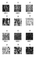
図9は、画像読取センサ125のCCDセンサ34によって読み取られる記録材の表面および記録材からの透過光量とCCDセンサ34からの出力を8×8ピクセルにディジタル処理した例との関係を示す図である。
FIG. 9 is a diagram showing the relationship between the surface of the recording material read by the
上記ディジタル処理は、CCDセンサ34からのアナログ出力をA/D変換して8ビットのピクセルデータに変換することによって行われる。
The digital processing is performed by A / D converting the analog output from the
図9において、映像40は、表面の紙の繊維が比較的がさついている所謂ラフ紙である記録材Aの表面拡大映像であり、映像41は、一般に使用される所謂普通紙である記録材Bの表面拡大映像である。映像42は、紙の繊維の圧縮が十分になされているグロス紙である記録材Cの表面拡大映像である。
In FIG. 9, an
CCDセンサ34に読み込まれたこれらの映像40〜42が、ディジタル処理され図9に示す映像43〜45となる。
These
図9において、映像46は、薄紙である記録材DのLED126による光照射領域の表面拡大映像であり、映像47は、一般的に使用される所謂普通紙である記録材EのLED126による光照射領域の表面拡大映像である。映像48は、厚紙である記録材FのLED126による光照射領域の表面拡大映像である。
In FIG. 9, an
CCDセンサ34に読み込まれたこれらの映像46〜48が、ディジタル処理され図9に示す49〜51となる。
These
このように、記録材の種類によって、表面の映像および透過光量は異なる。これは、主に紙の表面における繊維の状態および紙の繊維の圧縮状態が異なるために起こる現象である。 Thus, the image on the surface and the amount of transmitted light vary depending on the type of recording material. This is a phenomenon that occurs mainly because the fiber state on the paper surface and the compressed state of the paper fiber are different.
上述のように、CCDセンサ34で記録材表面を読み込みディジタル処理した映像および記録材の透過光量は、記録材の紙繊維の表面状態および紙繊維の圧縮状態の違いによる透過光量の違いによって判別が可能となる。
As described above, the amount of transmitted light of the image and recording material obtained by reading the surface of the recording material with the
次に、画像形成装置101に備えられた画像読取センサ125を用いた記録材判別の方法について説明する。画像読取センサ125を制御するセンサ制御部内のメイン制御部は、画像形成装置全体を制御する制御手段によって構成することもできる。画像読取センサ125の設置位置は、図3または図7と同様である。
Next, a recording material determination method using the
まず、LED33を点灯させ、CCDセンサ34が記録材の映像を読み込む。上記映像の読み込みは複数回にわたり上記記録材上の複数箇所において読み込む。
First, the
そして、LED33を消灯させた後、ゲイン調整手段及びフィルタ演算手段(図示せず)のゲイン演算及びフィルタ演算のための定数を調整する。このゲイン演算及びフィルタ演算は、CPUによってプログラマブルに処理される。
Then, after the
例えば、ゲイン演算は、CCDセンサ34からのアナログ出力のゲインを調整することによって行う。つまり、記録材表面より反射される反射光量が多すぎるとき、或いは、逆に少なすぎるときは、記録材表面の映像がよく読み取れない、即ち映像の変化が導けない場合には、ゲインを調整する。
For example, the gain calculation is performed by adjusting the gain of the analog output from the
又、フィルタ演算は、CCDセンサ34からのアナログ出力をA/D変換し8ビット、256階調のディジタルデータとしたときに、例えば、1/32,1/16,1/4等の演算によって行う。つまり、CCDセンサ34からの出力のノイズ成分を除去させる。
Also, the filter calculation is performed by, for example, calculating 1/32, 1/16, 1/4, etc., when the analog output from the
そして、次の映像比較演算する上で十分な映像情報が得られるか否かを判定し、十分な映像情報が得られると判定された場合には後述の映像比較演算を実行し、この映像比較演算結果と、どの給紙口からの記録材であるかを示す情報に基づき紙種を判定する。 Then, it is determined whether or not sufficient video information can be obtained for the next video comparison calculation. When it is determined that sufficient video information can be obtained, a video comparison calculation described later is executed, and this video comparison is performed. The paper type is determined based on the calculation result and information indicating from which paper feed opening the recording material is.
次に、上記の映像比較演算の方法について説明する。 Next, the video comparison calculation method will be described.
上記映像比較演算においては、記録材表面の複数箇所の映像を読み込んだ結果から、最大濃度のピクセルDmaxと最低濃度のピクセルDminを導く。これを読み込んだ映像毎に実行し平均処理する。 In the video comparison calculation, the maximum density pixel Dmax and the minimum density pixel Dmin are derived from the result of reading the video at a plurality of locations on the surface of the recording material. This is executed for each read video and averaged.
つまり、記録材Aのように表面の紙繊維ががさついている場合には繊維の影が多く発生する。その結果、明るい箇所と暗い箇所の差が大きく出るため、Dmax-Dminは大きくなる。 That is, when the paper fibers on the surface are sticking like the recording material A, many shadows of the fibers are generated. As a result, the difference between the bright part and the dark part is large, and Dmax-Dmin becomes large.
一方、記録材Cのような表面では、繊維の影が少なく、Dmax-Dminは小さくなる。 On the other hand, on the surface such as the recording material C, the shadow of the fiber is small and Dmax-Dmin is small.
このように、Dmax-Dminを演算し、その結果をあらかじめ(図2の309と同様な)EEPROM等のメモリに記憶してあるリファレンス値との比較結果と、どの給紙口からの記録材であるかを示す情報によって記録材の紙種を判定する。リファレンス値は、画像読取センサ125の設置位置に応じて、第一または第二の実施例における閾値の決定手法と同様にして決定することができる。即ち、実際に各給紙口から記録材を供給して各記録材におけるDmax-Dminを求め、これに基づいて、リファレンス値を作成することができる。
In this way, Dmax-Dmin is calculated, and the result is compared with the reference value stored in advance in a memory such as an EEPROM (similar to 309 in FIG. 2) and the recording material from which paper feed port. The paper type of the recording material is determined based on information indicating whether or not there is. The reference value can be determined in the same manner as the threshold value determination method in the first or second embodiment according to the installation position of the
上記の演算の結果、例えば、グロス紙と判定された場合、LED126は点灯せずに、その紙種に応じた現像バイアス条件、定着温度を設定する。
As a result of the above calculation, for example, when it is determined that the paper is glossy paper, the
しかし、グロス紙以外と判定された場合、紙の表面繊維状態だけでは、薄紙、普通紙、厚紙を正確に判別することができない。そこで、紙繊維の圧縮状態を調べるため、LED126を点灯させ、CCDセンサ34がLED126の光照射領域内の表面画像を読み込む。そして、全ピクセルの平均値を演算する。
However, when it is determined that the paper is not gloss paper, thin paper, plain paper, and thick paper cannot be accurately determined only by the surface fiber state of the paper. Therefore, in order to check the compression state of the paper fiber, the
つまり、記録材Dのように繊維の圧縮が小さい場合には、平均値が高く、記録材Fのように繊維の圧縮が高い場合には、平均値が低い。 That is, when the fiber compression is small like the recording material D, the average value is high, and when the fiber compression is high like the recording material F, the average value is low.
そしてLED126を消灯後、この平均値をあらかじめEEPROM等のメモリに記憶してあるリファレンス値と比較し、その結果と、どの給紙口からの記録材であるかを示す情報に基づき薄紙、普通紙、厚紙を判定する。
Then, after the
メイン制御部は、CCDセンサ34からの映像サンプリング処理、ゲインおよびフィルタ演算処理をリアルタイムにて処理する必要があるため、ディジタルシグナルプロセッサ(DSP)を用いることが望ましい。
Since the main control unit needs to process the video sampling processing, gain and filter calculation processing from the
以上のように、本実施例によれば記録材判別手段が、映像読み取り装置を備えた場合でも、給紙口ごとに最適な判別テーブル(リファレンス値)を備えることで、従来よりも最適な記録材の種類に応じた印字モードを設定することが可能である。 As described above, according to this embodiment, even when the recording material determination unit includes the image reading device, the optimal determination table (reference value) is provided for each sheet feeding port, so that the optimal recording can be achieved. It is possible to set a print mode according to the type of material.
125、200、206、207 記録材判別センサ
33、126、201、204、208、209 LED
34、202、203 受光部
105 記録紙搬送ガイド
35、36、211〜214 スリット
301〜304 発光部
305 発光素子制御部
306 メイン制御部
307 信号処理
308 比較部
309 メモリ
105 中間転写体
122 定着部
102 カセットトレイ
103 カセット給紙ローラ
123 マルチトレイ
124 マルチ給紙ローラ
125, 200, 206, 207 Recording
34, 202, 203
Claims (9)
前記光学的な情報は反射光であることを特徴とする画像形成装置。 In claim 1,
Image forming apparatus, wherein the optical information is reflected light.
前記光学的な情報は透過光であることを特徴とする画像形成装置。 In claim 1,
Image forming apparatus, wherein the optical information is transmitted light.
前記光学的な情報は反射光及び透過光であることを特徴とする画像形成装置。 In claim 1,
Image forming apparatus, wherein the optical information is reflected and transmitted light.
前記記録材判別手段は、前記搬送路上における記録材の表面への光照射領域内を映像として読み取り出力する読取手段を有することを特徴とする画像形成装置。 In any one of Claims 1 thru | or 4,
The image forming apparatus according to claim 1, wherein the recording material determination unit includes a reading unit that reads and outputs a light irradiation area on the surface of the recording material on the conveyance path as an image.
前記記録材判別手段は、前記光学的な情報を取得する2つの受光手段を有することを特徴とする画像形成装置。 In any one of claims 1, 2, 4 and 5.
The recording material discrimination device, an image forming apparatus characterized by having two light receiving means for acquiring the optical information.
前記個別の記録材を判別する情報は、前記各給紙口からの記録材に対して前記記録材判別手段による判別を実行して得られた結果を参照して作成することを特徴とする画像形成装置。 In any one of Claims 1 thru | or 6.
Information to determine the individual recording materials, image, characterized in that to create with reference to results obtained by executing the determination by the recording material determining means said the recording material from the sheet feeding port Forming equipment.
前記記録材判別手段は、前記搬送路における前記複数の給紙口から供給される各記録材の合流後の位置で光照射を実行することを特徴とする画像形成装置。 In any one of Claims 1 thru | or 7,
The image forming apparatus according to claim 1, wherein the recording material determination unit performs light irradiation at a position after joining of the recording materials supplied from the plurality of paper feeding ports in the conveyance path.
前記記録材判別手段は、前記搬送路における前記複数の給紙口から供給される各記録材の合流前の各位置で独立して光照射を実行することを特徴とする画像形成装置。 In any one of Claims 1 thru | or 7,
The image forming apparatus according to claim 1, wherein the recording material determination unit independently performs light irradiation at each position before joining of the recording materials supplied from the plurality of paper feeding ports in the conveyance path.
Priority Applications (1)
| Application Number | Priority Date | Filing Date | Title |
|---|---|---|---|
| JP2006056778A JP4810257B2 (en) | 2006-03-02 | 2006-03-02 | Image forming apparatus |
Applications Claiming Priority (1)
| Application Number | Priority Date | Filing Date | Title |
|---|---|---|---|
| JP2006056778A JP4810257B2 (en) | 2006-03-02 | 2006-03-02 | Image forming apparatus |
Publications (3)
| Publication Number | Publication Date |
|---|---|
| JP2007233186A JP2007233186A (en) | 2007-09-13 |
| JP2007233186A5 JP2007233186A5 (en) | 2009-04-16 |
| JP4810257B2 true JP4810257B2 (en) | 2011-11-09 |
Family
ID=38553819
Family Applications (1)
| Application Number | Title | Priority Date | Filing Date |
|---|---|---|---|
| JP2006056778A Active JP4810257B2 (en) | 2006-03-02 | 2006-03-02 | Image forming apparatus |
Country Status (1)
| Country | Link |
|---|---|
| JP (1) | JP4810257B2 (en) |
Families Citing this family (8)
| Publication number | Priority date | Publication date | Assignee | Title |
|---|---|---|---|---|
| JP6283995B2 (en) * | 2013-12-03 | 2018-02-28 | 株式会社リコー | Apparatus and image forming system for detecting sheet material information |
| JP6245515B2 (en) * | 2013-12-12 | 2017-12-13 | 株式会社リコー | Image forming apparatus |
| JP6241734B2 (en) | 2013-12-26 | 2017-12-06 | 株式会社リコー | Apparatus and image forming system for detecting sheet material information |
| JP6440009B2 (en) | 2014-04-10 | 2018-12-19 | 株式会社リコー | Sheet material discrimination apparatus and image forming apparatus |
| JP6448262B2 (en) * | 2014-09-05 | 2019-01-09 | キヤノン株式会社 | Recording material detection sensor and image forming apparatus |
| US9890003B2 (en) | 2014-09-30 | 2018-02-13 | Ricoh Company, Ltd. | Sheet discriminator and image forming apparatus incorporating the sheet discriminator |
| JP6501167B2 (en) * | 2018-02-05 | 2019-04-17 | 株式会社リコー | Device for detecting sheet material information and image forming system |
| JP2019137515A (en) * | 2018-02-09 | 2019-08-22 | コニカミノルタ株式会社 | Image formation apparatus, recording medium discrimination method and recording medium discrimination program |
Family Cites Families (2)
| Publication number | Priority date | Publication date | Assignee | Title |
|---|---|---|---|---|
| JP4478669B2 (en) * | 2005-08-31 | 2010-06-09 | キヤノン株式会社 | Sensor and recording apparatus using the same |
| JP4607716B2 (en) * | 2005-09-06 | 2011-01-05 | ニスカ株式会社 | Image forming apparatus |
-
2006
- 2006-03-02 JP JP2006056778A patent/JP4810257B2/en active Active
Also Published As
| Publication number | Publication date |
|---|---|
| JP2007233186A (en) | 2007-09-13 |
Similar Documents
| Publication | Publication Date | Title |
|---|---|---|
| JP4428855B2 (en) | Image forming apparatus | |
| JP4993653B2 (en) | Recording material discriminating apparatus, image forming apparatus and method thereof | |
| JP4810257B2 (en) | Image forming apparatus | |
| JP4454914B2 (en) | Image reading apparatus and image forming apparatus | |
| JP5159445B2 (en) | Recording material discrimination apparatus and image forming apparatus | |
| US7558492B2 (en) | Image forming apparatus and image forming method | |
| JP2010283670A (en) | Recording-medium imaging device, and image forming apparatus | |
| JP2008096617A (en) | Image forming apparatus | |
| JP2007206167A (en) | Image forming apparatus and control method therefor | |
| JP4424742B2 (en) | Image forming apparatus | |
| JP2005017541A (en) | Image forming method and image forming apparatus | |
| JP2007057891A (en) | Image forming apparatus | |
| JP2007022721A (en) | Image forming device | |
| JP2008032848A (en) | Paper surface property detection sensor and image forming apparatus equipped therewith | |
| JP4440319B2 (en) | Paper surface detection apparatus and image forming apparatus | |
| JP4700866B2 (en) | Image forming apparatus | |
| JP4424740B2 (en) | Recording material discrimination device | |
| JP2006264833A (en) | Recording material discriminating device and image forming device | |
| JP2006117363A (en) | Image forming device | |
| JP4861442B2 (en) | Image forming apparatus | |
| JP2009058613A (en) | Image forming apparatus | |
| JP2006184504A (en) | Kind-discriminating device for recording material, and image forming apparatus | |
| JP4741811B2 (en) | Image forming apparatus | |
| JP2003063692A (en) | Image forming device, method for taking measure to double feed, and recording medium | |
| JP2005037647A (en) | Image forming apparatus |
Legal Events
| Date | Code | Title | Description |
|---|---|---|---|
| A521 | Request for written amendment filed |
Free format text: JAPANESE INTERMEDIATE CODE: A523 Effective date: 20090302 |
|
| A621 | Written request for application examination |
Free format text: JAPANESE INTERMEDIATE CODE: A621 Effective date: 20090302 |
|
| RD02 | Notification of acceptance of power of attorney |
Free format text: JAPANESE INTERMEDIATE CODE: A7422 Effective date: 20101106 |
|
| TRDD | Decision of grant or rejection written | ||
| A01 | Written decision to grant a patent or to grant a registration (utility model) |
Free format text: JAPANESE INTERMEDIATE CODE: A01 Effective date: 20110812 |
|
| A01 | Written decision to grant a patent or to grant a registration (utility model) |
Free format text: JAPANESE INTERMEDIATE CODE: A01 |
|
| A61 | First payment of annual fees (during grant procedure) |
Free format text: JAPANESE INTERMEDIATE CODE: A61 Effective date: 20110822 |
|
| FPAY | Renewal fee payment (event date is renewal date of database) |
Free format text: PAYMENT UNTIL: 20140826 Year of fee payment: 3 |
|
| R151 | Written notification of patent or utility model registration |
Ref document number: 4810257 Country of ref document: JP Free format text: JAPANESE INTERMEDIATE CODE: R151 |