JP4806348B2 - Method and apparatus for testing an object - Google Patents
Method and apparatus for testing an object Download PDFInfo
- Publication number
- JP4806348B2 JP4806348B2 JP2006517049A JP2006517049A JP4806348B2 JP 4806348 B2 JP4806348 B2 JP 4806348B2 JP 2006517049 A JP2006517049 A JP 2006517049A JP 2006517049 A JP2006517049 A JP 2006517049A JP 4806348 B2 JP4806348 B2 JP 4806348B2
- Authority
- JP
- Japan
- Prior art keywords
- implant
- attachment
- detector
- resonance frequency
- khz
- Prior art date
- Legal status (The legal status is an assumption and is not a legal conclusion. Google has not performed a legal analysis and makes no representation as to the accuracy of the status listed.)
- Active
Links
Images


Classifications
-
- A—HUMAN NECESSITIES
- A61—MEDICAL OR VETERINARY SCIENCE; HYGIENE
- A61B—DIAGNOSIS; SURGERY; IDENTIFICATION
- A61B5/00—Measuring for diagnostic purposes; Identification of persons
- A61B5/103—Detecting, measuring or recording devices for testing the shape, pattern, colour, size or movement of the body or parts thereof, for diagnostic purposes
-
- A—HUMAN NECESSITIES
- A61—MEDICAL OR VETERINARY SCIENCE; HYGIENE
- A61C—DENTISTRY; APPARATUS OR METHODS FOR ORAL OR DENTAL HYGIENE
- A61C19/00—Dental auxiliary appliances
- A61C19/04—Measuring instruments specially adapted for dentistry
-
- A—HUMAN NECESSITIES
- A61—MEDICAL OR VETERINARY SCIENCE; HYGIENE
- A61B—DIAGNOSIS; SURGERY; IDENTIFICATION
- A61B5/00—Measuring for diagnostic purposes; Identification of persons
- A61B5/05—Detecting, measuring or recording for diagnosis by means of electric currents or magnetic fields; Measuring using microwaves or radio waves
-
- A—HUMAN NECESSITIES
- A61—MEDICAL OR VETERINARY SCIENCE; HYGIENE
- A61C—DENTISTRY; APPARATUS OR METHODS FOR ORAL OR DENTAL HYGIENE
- A61C8/00—Means to be fixed to the jaw-bone for consolidating natural teeth or for fixing dental prostheses thereon; Dental implants; Implanting tools
Description
本発明は、ヒトまたは動物の対象の骨に取り付けられたインプラントなどの対象物を試験するための方法および装置に関する。 The present invention relates to a method and apparatus for testing an object such as an implant attached to the bone of a human or animal subject.
インプラントの使用は、骨内に準備された孔内への金属固定具の挿入を含む。治癒プロセス中、周囲の骨が、インプラント表面との密接な接触を発展させ、適切な時間の後、プロテーゼが固定具に取り付けられてもよい。このようなインプラントは、歯科および美容外科でしばしば使用される。 The use of the implant involves the insertion of a metal fastener into a hole prepared in the bone. During the healing process, the surrounding bone develops intimate contact with the implant surface, and after a suitable time, the prosthesis may be attached to the fixture. Such implants are often used in dentistry and cosmetic surgery.
骨とインプラント表面との間の結合の質を臨床的に観察する手段に対する必要性がある。配置の誤差、および早期のまたは不適切な装填によって、インプラントの不具合が生じることがある。インプラントの装填前に使用されることができる非破壊試験は、このタイプの不具合を減少させことを助け、インプラントがまだ満足できるものであることを確実にするために、使用中であるインプラントに定期的な試験が実行されることも可能にする。試験は、また、異なるインプラントシステム間の量的な比較も提供する。 There is a need for a means to clinically observe the quality of the bond between bone and the implant surface. Placement errors and premature or improper loading can cause implant failure. Non-destructive testing that can be used prior to implant loading helps reduce this type of failure and ensures that the implant is still satisfactory to ensure that the implant is still satisfactory. It is also possible to carry out typical tests. The test also provides a quantitative comparison between different implant systems.
インプラントの状態を試験するためにX線が使用されることもあるが、X線は、インプラントの周囲の全体の骨欠損の存在を示すことしかできない。視点の位置および角度を十分な精度で再現することが困難であるため、X線で時間にわたる一体化の進行を監視することも極めて困難である。異なる種類の試験は、雑ではあるが、インプラントに取り付けられた構造体を外科用器具で叩くことである。この試験は、十分なインプラントと最もひどく欠陥のあるシステムを区別することしかできない。 X-rays may be used to test the condition of the implant, but X-rays can only indicate the presence of an entire bone defect around the implant. Since it is difficult to reproduce the position and angle of the viewpoint with sufficient accuracy, it is extremely difficult to monitor the progress of integration over time with X-rays. A different type of test is to beat the structure attached to the implant with a surgical instrument, albeit with a minority. This test can only distinguish between a satisfactory implant and the most severely defective system.
国際特許出願第92/18053号は、ヒトまたは動物の対象の骨に取り付けられたインプラントを試験する方法に関する。この方法は、部材をインプラントと接触させるステップと、インプラントと接触したときの部材の少なくとも1つの共振周波数を検知するステップと、検知された共振周波数を、骨に対するインプラントの取付度に関して解釈するステップとを含む。しかし、この方法は、ワイヤを通じてインプラントと接触している解析ユニットを使用することを意味している。 International Patent Application No. 92/18053 relates to a method for testing an implant attached to the bone of a human or animal subject. The method includes contacting a member with an implant, detecting at least one resonance frequency of the member when in contact with the implant, and interpreting the detected resonance frequency with respect to the degree of attachment of the implant to the bone. including. However, this method means using an analysis unit that is in contact with the implant through a wire.
米国特許第3,355,933号および国際特許出願第99/46603号は、大きな対象物の表面振動を測定するための測定装置に関する。これらの文書に示されている装置は、患者の口などの小さな空間には適していない。 U.S. Pat. No. 3,355,933 and International Patent Application No. 99/46603 relate to a measuring device for measuring surface vibrations of large objects. The devices shown in these documents are not suitable for small spaces such as the patient's mouth.
本発明の主な目的は、対象物、特にインプラントなどの小さな空間内の対象物の非接触の試験装置および方法を提供することである。 The main object of the present invention is to provide a non-contact test apparatus and method for objects, particularly objects in small spaces such as implants.
本発明の別の目的は、インプラントとそのインプラントが取り付けられている骨との間の結合の品質および/または程度の信頼性高い指標を、非接触方式で与えることが可能な、非破壊試験を提供することである。 Another object of the present invention is a non-destructive test that can provide a reliable indicator of the quality and / or degree of bonding between an implant and the bone to which the implant is attached in a non-contact manner. Is to provide.
本発明の別の目的は、本発明に清浄な様相を提供する使い捨ての試験装置を提供することである。 Another object of the present invention is to provide a disposable test device that provides a clean aspect to the present invention.
これらの理由のために、骨などの対象物に取り付けられたインプラントを試験するために方法および装置が、提供される。方法は、部材をインプラントと接触させるステップと、インプラントと接触しているときの部材の少なくとも1つの共振周波数を非接触で検知するステップと、骨に対するインプラントの取付度に関して、検知された共振周波数を解釈するステップとを含む。方法は、部材をインプラントに脱着可能に取り付けるステップをさらに含む。好ましくは、部材は片持ち梁を備える。 For these reasons, methods and apparatus are provided for testing implants attached to objects such as bone. The method includes contacting the member with the implant, detecting at least one resonance frequency of the member when in contact with the implant in a non-contact manner, and detecting the detected resonance frequency with respect to the degree of attachment of the implant to the bone. Interpreting. The method further includes removably attaching the member to the implant. Preferably, the member comprises a cantilever.
本発明の最も好ましい実施形態によると、部材が磁性部分を備える。したがって、共振周波数が、コイルを用いて検知される。 According to the most preferred embodiment of the invention, the member comprises a magnetic part. Therefore, the resonance frequency is detected using the coil.
別の実施形態によると、部材がマーカーを備える。したがって、共振周波数が、照明検知器を用いて検知される。 According to another embodiment, the member comprises a marker. Therefore, the resonant frequency is detected using the illumination detector.
本発明の別の実施形態によると、部材が強磁性材料製である。したがって、共振周波数が、磁場を擾乱する前記部材を用いて検知される。 According to another embodiment of the invention, the member is made of a ferromagnetic material. Therefore, the resonance frequency is detected using the member that disturbs the magnetic field.
好ましくは、インプラントが、ねじ山付きのボアを備え、片持ち梁が、インプラントにまたはインプラント内へねじ留めされる。 Preferably, the implant comprises a threaded bore and the cantilever is screwed to or into the implant.
方法は、検知された共振周波数を、他のインプラントと接触している同じまたは同様の部材の共振周波数の1つまたは複数の値と比較するステップをさらに含む。あるステップでは、検知された共振周波数が、同じインプラントと接触している同じまたは同様の部材の共振周波数に関して、異なる時間で取得した1つまたは複数の値と比較される。 The method further includes comparing the sensed resonance frequency to one or more values of the resonance frequency of the same or similar member in contact with the other implant. In one step, the sensed resonance frequency is compared to one or more values obtained at different times with respect to the resonance frequency of the same or similar member in contact with the same implant.
方法は、部材を力で励振するステップと、部材の力に対する応答を検知するステップと、応答信号の電圧の励振信号の電圧に対する比である出力を導出するステップとをさらに含む。 The method further includes exciting the member with force, sensing a response to the force of the member, and deriving an output that is a ratio of the voltage of the response signal to the voltage of the excitation signal.
本発明は、また、骨に取り付けられたインプラントを試験するための装置に関する。装置は、インプラントに解放可能に取り付けられるように構成された部材と、インプラントに取り付けられたとき、部材の少なくとも1つの共振周波数を検知するための検知手段とを備える。部材は、検知可能な部分を備える。検知手段は、検知可能な部分の非接触の検知のための検知器を備える。 The invention also relates to a device for testing an implant attached to a bone. The apparatus comprises a member configured to be releasably attached to the implant and sensing means for sensing at least one resonant frequency of the member when attached to the implant. The member includes a detectable portion. The detection means includes a detector for non-contact detection of the detectable part.
最も好ましい実施形態によると、検知可能な部分が、磁性部材を備える。したがって、検知器がコイルを備える。装置は、増幅器、プロセッサ、およびデータ記憶装置をさらに備える。検知器によって検知された信号が、増幅器によって増幅され、解析される入力として印加される。励振に対する応答電圧の比を表す解析された出力が、プロセッサに供給され、プロセッサが、アナライザの振動子の周波数出力を変動させ、結果をデータ記憶装置に保管する。 According to the most preferred embodiment, the detectable part comprises a magnetic member. Therefore, the detector includes a coil. The apparatus further comprises an amplifier, a processor, and a data storage device. The signal detected by the detector is amplified by an amplifier and applied as an input to be analyzed. An analyzed output representing the ratio of response voltage to excitation is provided to the processor, which varies the frequency output of the analyzer's transducer and stores the result in a data store.
本発明の別の態様によると、検知可能な部分が、マーカーを備える。したがって、検知器が、照明検知器または照明器を備える。 According to another aspect of the invention, the detectable portion comprises a marker. Thus, the detector comprises an illumination detector or an illuminator.
本発明の別の態様によると、検知可能な部分が、強磁性材料から成る。 According to another aspect of the invention, the detectable portion comprises a ferromagnetic material.
本発明の別の態様によると、検知器が、外部磁場の擾乱を検知するためのコイルを備える。 According to another aspect of the invention, the detector comprises a coil for detecting disturbances in the external magnetic field.
最も好ましくは、部材が、片持ち梁を備える。有利には梁が、約1kHzから20kHz、好ましくは約1kHzから10kHz、およびより好ましくは8kHzのオーダーの周波数で共振するように配置または構成されている。 Most preferably, the member comprises a cantilever beam. Advantageously, the beam is arranged or configured to resonate at a frequency on the order of about 1 kHz to 20 kHz, preferably about 1 kHz to 10 kHz, and more preferably 8 kHz.
衛生上の理由のために、部材は廃棄可能である。 For hygienic reasons, the member can be discarded.
本発明は、また、骨に取り付けられたインプラントを試験するために設けられた使い捨てのインプラント試験部品に関する。この使い捨てのインプラント試験部品は、検知器を用いて非接触で検知され得る検出可能な部分を備える。 The invention also relates to a disposable implant test component provided for testing an implant attached to a bone. The disposable implant test component comprises a detectable portion that can be sensed contactlessly using a detector.
本発明を、添付の図面を参照にして、単なる例示としてここでさらに説明する。 The invention will now be further described, by way of example only, with reference to the accompanying drawings.
図1を参照すると、装置100は、2つの部分を備え、片持ち梁の形態の部材110が、ねじ山付きセクション111を用いて埋め込まれた固定具120に取り付けられている。インプラント固定具は、骨130、通常ヒトの顎骨のセクション内に、ねじ山付きセクション112によって取り付けられた歯科用インプラント、あるいはヒトまたは動物のためのその他のいずれかのタイプのインプラントでありうる。インプラント120は、チタンなどの金属から、セラミック材料から、またはいずれかの他の適切な材料から形成された、いくつかの知られているタイプのうちのいずれか1つであってよい。これは、たとえば、英国のNobel Biocareによって供給されているタイプのものであってよい。部材110は、磁性部材140を備える。磁性部材140は、梁110の一方の端部、たとえば自由端に設けられることができる、または梁の内部に組み込まれることができる。
Referring to FIG. 1, the
装置の第2の部分は、プローブ151と応答アナライザユニット152とを備える試験装置150を備える。プローブ150は、磁性部材の振動を検知するためのコイル153を備える。
The second part of the device comprises a
梁内で振動を発生させるために、梁は励振されなければならない。このことは、手動でまたは電気励振器を用いて、梁に力Fを印加することを通じて行われることができる。 In order to generate vibrations in the beam, the beam must be excited. This can be done manually or using an electrical exciter through applying a force F to the beam.
プローブ151によって検知された信号が、増幅器154によって増幅され、アナライザへの入力として印加される。励振に対する応答電圧の比を表すアナライザからの出力が、マイクロプロセッサ155などのプロセッサに供給され、アナライザの振動子の周波数出力を変動させるために使用され、結果をデータ記憶装置156に保管する。結果は印刷されること、および/またはディスプレイなどに表示されることができる。
The signal detected by
本発明の第2の実施形態を示す図2をここで参照すると、本発明による装置200の第1の部分は、ねじ山付きセクション211を用いて埋め込まれた固定具220に取り付けられた前の実施形態のような片持ち梁の形態の部材210を備える。また、この場合、インプラント固定具は、骨230のセクション内のねじ山付きセクション212によって取り付けられた歯科用インプラントであってもよい。部材210は、この場合、梁210の一方の端部に配置された線などのマーキング240を備える。
Referring now to FIG. 2, which shows a second embodiment of the present invention, the first portion of the
装置の第2の部分は、プローブ251と応答アナライザユニット252とを備える試験装置250を備える。プローブ250は、好ましくはレーザーであるがこれに限定されない光源253aと、梁からの反射およびしたがって梁の振動を検知するための光検知器253bとを備える。光源は、好ましくはレーザーダイオードである。梁は、光の反射を行う、より暗い(または明るい)セクションなどの1つまたはいくつかのマーカーを備える。
The second part of the device comprises a
梁は、手動で、またはたとえば電気励振器を用いて、梁に力Fを印加することによって励振される。 The beam is excited manually or by applying a force F to the beam, for example using an electric exciter.
プローブの先端の光源が梁を照射し、光検知器253bが反射された光を検知する。検知された光信号が、検知器によって電気信号に変換され、プローブ251によって検知された信号が、増幅器254によって増幅され、アナライザに入力として印加される。励振に対する応答電圧の比を表すアナライザからの出力が、マイクロプロセッサ255などのプロセッサに供給され、アナライザの振動子の周波数出力を変化させるために使用され、結果をデータ記憶装置256内に保管する。結果は印刷されること、および/またはディスプレイなどに表示されることができる。
The light source at the tip of the probe irradiates the beam, and the
使用中、梁110が、事前に決定されたトルクで、たとえばトルクコントローラおよびカウンタツールを使用して、埋め込まれたインプラント120に固定、すなわちねじ留めされる。トルクによる共振周波数の変動は、このようなトルク変動が問題を呈すべきでないように、たとえば5Ncmから10Ncmのオーダーの、実用的なトルクの範囲にわたって比較的小さいことが見出だされている。
In use, the
好ましくは、本発明による梁は使い捨て可能であるが、必ずしもそうである必要はない。このことは、梁が、ねじで取り外され廃棄されることができることを意味し、衛生的な試験装置を提供する。 Preferably, the beam according to the invention is disposable, but this need not be the case. This means that the beam can be removed with a screw and discarded, providing a hygienic test device.
図3は、図1の装置でおおまかに共振周波数を得るために使用される、粗い走査によるデータを示している。次に、この領域の周囲のより精細な走査が、この周波数、通常第1の周波数すなわち基本周波数をより正確に識別するために使用される。この周波数が記録され、たとえば、同様の結合段階での他のインプラントのためのデータと比較される。 FIG. 3 shows the coarse scan data used to obtain the approximate resonant frequency in the apparatus of FIG. A finer scan around this area is then used to more accurately identify this frequency, usually the first or fundamental frequency. This frequency is recorded and compared, for example, with data for other implants at a similar coupling stage.
特定のインプラントについては、共振周波数が、骨への取付度とともに変動することが予想される。したがって、検知された共振周波数を同様のインプラントに対して前に集められたデータと比較することによって、インプラントの取付度の指標を得ることができる。 For a particular implant, the resonant frequency is expected to vary with the degree of attachment to the bone. Therefore, an indication of the degree of attachment of the implant can be obtained by comparing the sensed resonant frequency with previously collected data for similar implants.
振幅変化ではなく、共振周波数偏移の検知および比較に基づいた技術は、インプラント/組織インターフェイスの品質をその剛性の関数として、およびインプラントを包囲する周縁の骨のレベルまたは高さの関数として骨損失と関連付けて決定するために効果的である。 Techniques based on the detection and comparison of resonance frequency shifts rather than amplitude changes, bone loss as a function of implant / tissue interface quality as a function of its stiffness and as a function of the level or height of the peripheral bone surrounding the implant It is effective to determine in association with.
梁は、好ましくは、たとえばチタンまたはアルミニウムなどの金属製材料のものであり、1kHzから20kHz、より具体的には1kHzから10kHz、および好ましくは約8kHzの範囲内のオーダーの系(配置されたインプラントおよび梁)の共振周波数範囲を提供するような寸法にされている。たとえば、図1の実施形態では、直立した梁は約1cmの高さであってよい。 The beam is preferably of a metallic material, for example titanium or aluminum, and is of a system (arranged implant) in the range of 1 kHz to 20 kHz, more specifically 1 kHz to 10 kHz, and preferably about 8 kHz. And the beam) are dimensioned to provide a resonant frequency range. For example, in the embodiment of FIG. 1, the upright beam may be about 1 cm high.
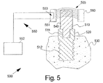
さらに別の実施形態では、図5に示すように、本発明のこの態様による装置500の第1の部分は、ねじ山付きセクション511を用いて埋め込まれた固定具520に取り付けられた強磁性材料製の片持ち梁の形態の部材510を備える。また、この場合、インプラント固定具は、骨530のセクション内にねじ山付きセクション512によって取り付けられた歯科用インプラントであってよい。したがって、この場合部材510は、それ自体検知可能な部品540である。
In yet another embodiment, as shown in FIG. 5, the first portion of the
梁510は、磁場発生器560によって発生される外部磁場565を用いて励振される。
試験装置550は、プローブ551と応答アナライザユニット552とを備える。プローブは、磁場発生器の部品であってもよい。プローブ550は、磁場565内の干渉を検知するためのコイル553を備える。解析は、第1の実施形態に関連して説明したように実行されてもよい。
The
磁場発生器は、直流場を発生させるための永久磁石または、交流場を発生させるためのコイルであってもよい。プローブは、外部に配置されてもよい。 The magnetic field generator may be a permanent magnet for generating a direct current field or a coil for generating an alternating current field. The probe may be disposed outside.
特許請求の範囲で規定されたように、本発明の範囲から逸脱することなく、様々な修正が行われてもよいことを理解されよう。 It will be understood that various modifications may be made without departing from the scope of the invention as defined in the claims.
トランスデューサまたはゲージ、および場合によっては梁が、装置の滅菌中トランスデューサを保護するために、空気乾燥アクリル材料で被覆されてもよい。部材は、片持ち梁以外の形態をとってもよい。梁は、基本的に直線状である代わりに、ほぼU字状であり、その底部によってインプラントまたは当接部と接続されてもよい。さらに、紫外線、音などの代替となる検知器が使用されてもよい。 The transducer or gauge, and possibly the beam, may be coated with an air-dried acrylic material to protect the transducer during device sterilization. The member may take a form other than the cantilever. Instead of being essentially straight, the beam is generally U-shaped and may be connected to the implant or abutment by its bottom. Furthermore, detectors that are alternatives to ultraviolet light, sound, etc. may be used.
本発明は、インプラントに限定されず、ねじ、リベット、ボルト、またはピンなどの対象物の保持が試験される、好ましくはすべての小さな空間に適用される。 The invention is not limited to implants, but preferably applies to all small spaces where the retention of objects such as screws, rivets, bolts or pins is tested.
Claims (28)
磁気および/または光学的に検出可能な部材(110、210、510)を前記アタッチメントと接触させるステップと、
前記磁気および/または光学的に検出可能な部材(110、210、510)を振動させるステップと、
前記磁気および/または光学的に検出可能な部材(110、210、510)の少なくとも1つの共振周波数を電磁および/または光検出器を用いて非接触で検知するステップと、
検知された共振周波数から、対象物に対するアタッチメントの取付度の指標を得るステップとを含む方法。A method for testing an attachment (120, 220, 520) attached to an object (130, 230, 530), comprising:
Contacting a magnetically and / or optically detectable member (110, 210, 510) with the attachment;
Vibrating the magnetically and / or optically detectable member (110, 210, 510);
Sensing at least one resonance frequency of the magnetically and / or optically detectable member (110, 210, 510) in a non-contact manner using an electromagnetic and / or photodetector;
Obtaining an index of the degree of attachment of the attachment to the object from the detected resonance frequency .
前記インプラントに解放可能に取り付けられるように構成された部材(110、210、510)と、
部材がインプラントに取り付けられたとき、部材の少なくとも1つの共振周波数を検知するための検知手段(150、250、550)とを備える、システムであって、
前記部材(110、210)が、磁気および/または光学的に検知可能な部分(140、240、540)を備えること、および
前記検知手段(150、250)が、前記部分の非接触の検知のための電磁および/または光検知器(150、250)を備えることを特徴とするシステム。A system (100, 200, 500) for testing an implant (120, 220, 520) attached to a bone (130, 230, 530);
A member (110, 210, 510) configured to be releasably attached to the implant;
Sensing means (150, 250, 550) for sensing at least one resonance frequency of the member when the member is attached to the implant,
The member (110, 210) comprises a magnetically and / or optically detectable part (140, 240, 540), and the detection means (150, 250) for non-contact detection of the part; A system comprising an electromagnetic and / or light detector (150, 250) for the purpose.
Applications Claiming Priority (3)
| Application Number | Priority Date | Filing Date | Title |
|---|---|---|---|
| SE0301825A SE0301825L (en) | 2003-06-19 | 2003-06-19 | Method and system for implant certification |
| SE0301825-6 | 2003-06-19 | ||
| PCT/SE2004/000998 WO2004110272A1 (en) | 2003-06-19 | 2004-06-21 | Method and arrangement relating to testing objects |
Publications (2)
| Publication Number | Publication Date |
|---|---|
| JP2006527627A JP2006527627A (en) | 2006-12-07 |
| JP4806348B2 true JP4806348B2 (en) | 2011-11-02 |
Family
ID=27607388
Family Applications (1)
| Application Number | Title | Priority Date | Filing Date |
|---|---|---|---|
| JP2006517049A Active JP4806348B2 (en) | 2003-06-19 | 2004-06-21 | Method and apparatus for testing an object |
Country Status (9)
| Country | Link |
|---|---|
| US (1) | US8979532B2 (en) |
| EP (1) | EP1641394B1 (en) |
| JP (1) | JP4806348B2 (en) |
| KR (1) | KR101302111B1 (en) |
| DK (1) | DK1641394T3 (en) |
| ES (1) | ES2392534T3 (en) |
| PL (1) | PL1641394T3 (en) |
| SE (2) | SE0301825L (en) |
| WO (1) | WO2004110272A1 (en) |
Families Citing this family (16)
| Publication number | Priority date | Publication date | Assignee | Title |
|---|---|---|---|---|
| SE0301825L (en) | 2003-06-19 | 2005-02-18 | Integration Diagnostics Ltd | Method and system for implant certification |
| CA2660713A1 (en) * | 2006-08-17 | 2008-02-21 | The Governors Of The University Of Alberta | Apparatus and method for assessing percutaneous implant integrity |
| DE102006051032A1 (en) * | 2006-10-21 | 2008-04-30 | Fraunhofer-Gesellschaft zur Förderung der angewandten Forschung e.V. | System for determining the anchoring position of an implanted endoprosthesis comprises using a magnet or a ferromagnetic element arranged on the endoprosthesis and oscillated using an excitation coil |
| SE1001237A1 (en) * | 2010-12-29 | 2012-06-30 | Ostell Ab | Device for quality testing of a dental bracket |
| TWI546060B (en) * | 2013-12-02 | 2016-08-21 | 國立中央大學 | System, apparatus and method for detecting bone defects |
| KR101643586B1 (en) * | 2015-02-12 | 2016-07-29 | 오스템임플란트 주식회사 | Orthodontic screw adapter |
| WO2016204684A1 (en) * | 2015-06-18 | 2016-12-22 | Osstell Ab | Implant stability measuring device and method |
| JP2017144061A (en) * | 2016-02-17 | 2017-08-24 | 学校法人慶應義塾 | Method for evaluating installation strength of orthopedic implant, orthopedic implant, and orthopedic jig |
| GB2554456A (en) * | 2016-09-29 | 2018-04-04 | Osstell Ab | A probe |
| KR101838179B1 (en) * | 2016-12-19 | 2018-04-26 | 주식회사 써지덴트 | Measuring apparatus of implant fixing force |
| JP7288670B2 (en) * | 2017-03-10 | 2023-06-08 | ユニヴァーシティ オブ ワシントン | Method and system for measuring and evaluating stability of medical implants |
| EP3682842B1 (en) * | 2017-09-14 | 2024-05-01 | Keio University | Implant installation strength evaluation method, implant installation strength evaluation device, and program |
| BR112021006736B1 (en) * | 2018-12-21 | 2024-03-12 | Tmd Friction Services Gmbh | DEVICE AND METHOD FOR DETERMINING MECHANICAL PROPERTIES |
| JP2020146072A (en) * | 2019-03-11 | 2020-09-17 | 株式会社ナカニシ | Dental medical device |
| TWI729594B (en) | 2019-11-27 | 2021-06-01 | 國立中央大學 | Detecting device |
| US20210325437A1 (en) * | 2020-04-19 | 2021-10-21 | Research Electronics International, Llc | Cached Peak Graphical Display for Spectrum Analyzers |
Citations (3)
| Publication number | Priority date | Publication date | Assignee | Title |
|---|---|---|---|---|
| JPH0889517A (en) * | 1994-09-26 | 1996-04-09 | Tetsuo Takuno | Measuring instrument for unsteady degree for tooth |
| WO2001019248A1 (en) * | 1999-09-16 | 2001-03-22 | Integration Diagnostics Ltd | Device and method for establishing stability in an implant or unit |
| JP2003070752A (en) * | 2001-06-12 | 2003-03-11 | Yoshida Dental Mfg Co Ltd | Instrument for measurement, record, and communication of organism information using dental construction and method to control information input/output therefor |
Family Cites Families (20)
| Publication number | Priority date | Publication date | Assignee | Title |
|---|---|---|---|---|
| US3292426A (en) * | 1963-07-26 | 1966-12-20 | Joseph A Mccann | Vibration detection device |
| US3355933A (en) * | 1964-03-16 | 1967-12-05 | Robert G Rowe | Resonance vibration testing apparatus |
| US4362511A (en) * | 1981-07-09 | 1982-12-07 | John Jacklich | J Bolt |
| US4511330A (en) * | 1981-11-18 | 1985-04-16 | Medical Magnetics, Inc. | Integrated oral magnetic osteogenic appliances |
| YU128990A (en) | 1989-07-11 | 1993-05-28 | Warner-Lambert Co. | PREPARATIONS OF POLYMER MIXTURES CONTAINING DESTRUCTURED STARCH |
| GB9107700D0 (en) * | 1991-04-11 | 1991-05-29 | Imperial College | Testing implants |
| US5555884A (en) | 1992-12-16 | 1996-09-17 | Kabushiki Kaisha Egawa | Measuring method by using resonance of a resonance medium |
| US5518008A (en) * | 1994-08-25 | 1996-05-21 | Spectral Sciences Research Corporation | Structural analyzer, in particular for medical implants |
| US6161046A (en) * | 1996-04-09 | 2000-12-12 | Maniglia; Anthony J. | Totally implantable cochlear implant for improvement of partial and total sensorineural hearing loss |
| JPH10201771A (en) | 1997-01-20 | 1998-08-04 | Injietsukusu:Kk | Crown repair material |
| US6034296A (en) * | 1997-03-11 | 2000-03-07 | Elvin; Niell | Implantable bone strain telemetry sensing system and method |
| CN1548963A (en) | 1998-03-09 | 2004-11-24 | Otm��������˾ | Optical translational measurement |
| US6413220B1 (en) * | 1998-05-08 | 2002-07-02 | Emery S. Rose | Surface acoustic wave periodontal probe and method of detecting periodontal disease |
| US6712778B1 (en) * | 1999-09-30 | 2004-03-30 | The Uab Research Foundation | Implantable mechanical force sensor |
| US6573706B2 (en) * | 1999-11-18 | 2003-06-03 | Intellijoint Systems Ltd. | Method and apparatus for distance based detection of wear and the like in joints |
| US20020143268A1 (en) * | 2001-04-03 | 2002-10-03 | Neil Meredith | Bone implant testing |
| DE10137011C2 (en) * | 2001-07-28 | 2003-12-04 | Aesculap Ag & Co Kg | Medical implant system |
| ES2232784T3 (en) * | 2001-07-28 | 2005-06-01 | AESCULAP AG & CO. KG | MEDICAL IMPLANT SYSTEM. |
| SE0301825L (en) | 2003-06-19 | 2005-02-18 | Integration Diagnostics Ltd | Method and system for implant certification |
| US20050026113A1 (en) * | 2003-07-30 | 2005-02-03 | Jiunn-Liang Chen | Micro-implantable apparatus and method for the stability assessment of a two-stage dental implant |
-
2003
- 2003-06-19 SE SE0301825A patent/SE0301825L/en not_active Application Discontinuation
-
2004
- 2004-06-21 KR KR1020057024381A patent/KR101302111B1/en active IP Right Grant
- 2004-06-21 SE SE04749036T patent/SE1641394T5/xx unknown
- 2004-06-21 ES ES04749036T patent/ES2392534T3/en active Active
- 2004-06-21 WO PCT/SE2004/000998 patent/WO2004110272A1/en active Application Filing
- 2004-06-21 JP JP2006517049A patent/JP4806348B2/en active Active
- 2004-06-21 PL PL04749036T patent/PL1641394T3/en unknown
- 2004-06-21 DK DK04749036.2T patent/DK1641394T3/en active
- 2004-06-21 EP EP04749036A patent/EP1641394B1/en active Active
-
2010
- 2010-12-29 US US12/980,717 patent/US8979532B2/en not_active Expired - Fee Related
Patent Citations (3)
| Publication number | Priority date | Publication date | Assignee | Title |
|---|---|---|---|---|
| JPH0889517A (en) * | 1994-09-26 | 1996-04-09 | Tetsuo Takuno | Measuring instrument for unsteady degree for tooth |
| WO2001019248A1 (en) * | 1999-09-16 | 2001-03-22 | Integration Diagnostics Ltd | Device and method for establishing stability in an implant or unit |
| JP2003070752A (en) * | 2001-06-12 | 2003-03-11 | Yoshida Dental Mfg Co Ltd | Instrument for measurement, record, and communication of organism information using dental construction and method to control information input/output therefor |
Also Published As
| Publication number | Publication date |
|---|---|
| KR101302111B1 (en) | 2013-09-03 |
| WO2004110272A1 (en) | 2004-12-23 |
| PL1641394T3 (en) | 2013-01-31 |
| DK1641394T3 (en) | 2012-10-29 |
| KR20060067926A (en) | 2006-06-20 |
| EP1641394B1 (en) | 2012-08-08 |
| US8979532B2 (en) | 2015-03-17 |
| SE1641394T5 (en) | 2016-02-02 |
| JP2006527627A (en) | 2006-12-07 |
| EP1641394A1 (en) | 2006-04-05 |
| US20110200965A1 (en) | 2011-08-18 |
| SE0301825D0 (en) | 2003-06-19 |
| ES2392534T3 (en) | 2012-12-11 |
| SE0301825L (en) | 2005-02-18 |
Similar Documents
| Publication | Publication Date | Title |
|---|---|---|
| JP4806348B2 (en) | Method and apparatus for testing an object | |
| JP3430263B2 (en) | Inspection of implant | |
| US20140072929A1 (en) | Method and arrangement relating to testing objects | |
| US8391958B2 (en) | Method and arrangement relating to testing objects | |
| JPH07508665A (en) | Pushing device for arthroscopy and how to use it | |
| US20070270684A1 (en) | Method and Arrangement Relating to Testing Objects | |
| JP2014507194A (en) | Dental installation quality inspection device | |
| Kim et al. | A new method for the evaluation of dental implant stability using an inductive sensor | |
| Zhuang et al. | A noncontact detection technique for interfacial bone defects and osseointegration assessment surrounding dental implants | |
| JP7281770B2 (en) | IMPLANT INSTALLATION STRENGTH EVALUATION METHOD, IMPLANT INSTALLATION STRENGTH EVALUATION DEVICE, AND PROGRAM | |
| Zhuang et al. | Noncontact vibro-acoustic detection technique for dental osseointegration examination | |
| Pan et al. | Design/exploration and verification of an electromagnetic probe for assessing dental implant osseointegration | |
| JP7059287B2 (en) | probe | |
| Khuntia et al. | Resonance frequency analysis and oral implant stability: a long term relationship | |
| Araújo et al. | Current literature review on methods for measuring the stability of osseointegrable implants. | |
| SE1451369A1 (en) | Device for quality testing of a dental bracket | |
| El-Wassefy¹ et al. | Current literature review on methods for measuring the stability of osseointegrable implants. | |
| Mandal et al. | Bridge to integration and implant stability: A review. |
Legal Events
| Date | Code | Title | Description |
|---|---|---|---|
| A621 | Written request for application examination |
Free format text: JAPANESE INTERMEDIATE CODE: A621 Effective date: 20070530 |
|
| A131 | Notification of reasons for refusal |
Free format text: JAPANESE INTERMEDIATE CODE: A131 Effective date: 20100406 |
|
| A601 | Written request for extension of time |
Free format text: JAPANESE INTERMEDIATE CODE: A601 Effective date: 20100630 |
|
| A602 | Written permission of extension of time |
Free format text: JAPANESE INTERMEDIATE CODE: A602 Effective date: 20100707 |
|
| A521 | Request for written amendment filed |
Free format text: JAPANESE INTERMEDIATE CODE: A523 Effective date: 20101006 |
|
| A131 | Notification of reasons for refusal |
Free format text: JAPANESE INTERMEDIATE CODE: A131 Effective date: 20101130 |
|
| A601 | Written request for extension of time |
Free format text: JAPANESE INTERMEDIATE CODE: A601 Effective date: 20110222 |
|
| A602 | Written permission of extension of time |
Free format text: JAPANESE INTERMEDIATE CODE: A602 Effective date: 20110301 |
|
| A521 | Request for written amendment filed |
Free format text: JAPANESE INTERMEDIATE CODE: A523 Effective date: 20110506 |
|
| TRDD | Decision of grant or rejection written | ||
| A01 | Written decision to grant a patent or to grant a registration (utility model) |
Free format text: JAPANESE INTERMEDIATE CODE: A01 Effective date: 20110802 |
|
| A01 | Written decision to grant a patent or to grant a registration (utility model) |
Free format text: JAPANESE INTERMEDIATE CODE: A01 |
|
| A61 | First payment of annual fees (during grant procedure) |
Free format text: JAPANESE INTERMEDIATE CODE: A61 Effective date: 20110812 |
|
| R150 | Certificate of patent or registration of utility model |
Ref document number: 4806348 Country of ref document: JP Free format text: JAPANESE INTERMEDIATE CODE: R150 Free format text: JAPANESE INTERMEDIATE CODE: R150 |
|
| FPAY | Renewal fee payment (event date is renewal date of database) |
Free format text: PAYMENT UNTIL: 20140819 Year of fee payment: 3 |
|
| S111 | Request for change of ownership or part of ownership |
Free format text: JAPANESE INTERMEDIATE CODE: R313113 |
|
| R350 | Written notification of registration of transfer |
Free format text: JAPANESE INTERMEDIATE CODE: R350 |
|
| R250 | Receipt of annual fees |
Free format text: JAPANESE INTERMEDIATE CODE: R250 |
|
| R250 | Receipt of annual fees |
Free format text: JAPANESE INTERMEDIATE CODE: R250 |
|
| R250 | Receipt of annual fees |
Free format text: JAPANESE INTERMEDIATE CODE: R250 |
|
| R250 | Receipt of annual fees |
Free format text: JAPANESE INTERMEDIATE CODE: R250 |
|
| R250 | Receipt of annual fees |
Free format text: JAPANESE INTERMEDIATE CODE: R250 |
|
| R250 | Receipt of annual fees |
Free format text: JAPANESE INTERMEDIATE CODE: R250 |
|
| R250 | Receipt of annual fees |
Free format text: JAPANESE INTERMEDIATE CODE: R250 |
|
| R250 | Receipt of annual fees |
Free format text: JAPANESE INTERMEDIATE CODE: R250 |
|
| R250 | Receipt of annual fees |
Free format text: JAPANESE INTERMEDIATE CODE: R250 |
|
| R250 | Receipt of annual fees |
Free format text: JAPANESE INTERMEDIATE CODE: R250 |