JP2017144061A - Method for evaluating installation strength of orthopedic implant, orthopedic implant, and orthopedic jig - Google Patents
Method for evaluating installation strength of orthopedic implant, orthopedic implant, and orthopedic jig Download PDFInfo
- Publication number
- JP2017144061A JP2017144061A JP2016028225A JP2016028225A JP2017144061A JP 2017144061 A JP2017144061 A JP 2017144061A JP 2016028225 A JP2016028225 A JP 2016028225A JP 2016028225 A JP2016028225 A JP 2016028225A JP 2017144061 A JP2017144061 A JP 2017144061A
- Authority
- JP
- Japan
- Prior art keywords
- implant
- vibrator
- orthopedic
- installation strength
- measurement
- Prior art date
- Legal status (The legal status is an assumption and is not a legal conclusion. Google has not performed a legal analysis and makes no representation as to the accuracy of the status listed.)
- Pending
Links
Images


Abstract
Description
本発明は、整形外科用インプラントの設置強度評価方法、整形外科用インプラント、および整形外科治具に関する。 The present invention relates to an installation strength evaluation method for an orthopedic implant, an orthopedic implant, and an orthopedic jig.
近年我が国では、高齢化により、腰部脊柱管狭窄症、変形性膝関節症、変形性股関節症等の変性疾患、および脊椎骨折、大腿骨骨折、上腕骨骨折、前腕骨骨折等の骨脆弱性骨折等の疾患が増加している。これに伴って、整形外科用インプラント(以下、単に「インプラント」と称することがある。)を使用した脊椎固定術、人工関節置換術、骨折観血的手術等の件数も急激に増加している。 In recent years, in Japan, due to aging, degenerative diseases such as lumbar spinal canal stenosis, knee osteoarthritis, hip osteoarthritis, and fragile bone fractures such as vertebral fractures, femoral fractures, humeral fractures, forearm fractures, etc. Diseases such as are increasing. Along with this, the number of spinal fusion, artificial joint replacement, fracture open surgery using orthopedic implants (hereinafter sometimes simply referred to as “implants”) has also increased rapidly. .
上述の各術式において、特に骨強度が低下している高齢者が患者の場合、術後におけるインプラントの緩みや脱転が大きな問題となっている(非特許文献1参照)。緩みや脱転を防ぐには、術中においてインプラントを設置するときに、設置強度を正確に評価できることが望ましい。 In each of the above-described surgical procedures, in particular, when an elderly person whose bone strength is reduced is a patient, loosening or dislodging of the implant after surgery is a serious problem (see Non-Patent Document 1). In order to prevent loosening and slipping, it is desirable that the installation strength can be accurately evaluated when the implant is installed during the operation.
現状、インプラントの設置強度は、術者が自分の経験や感覚で推測することが一般的であり、客観的評価が行われているとは言い難い。また、インプラントの設置強度を評価する試みとして、インプラントの埋入トルクや引き抜き強度を計測してこれを設置強度の指標として用いることが検討および報告されている(例えば、非特許文献1参照。)。 At present, the installation strength of implants is generally estimated by an operator based on his / her own experience and feeling, and it cannot be said that an objective evaluation has been performed. Further, as an attempt to evaluate the installation strength of the implant, it has been studied and reported to measure the implantation torque and pull-out strength of the implant and use this as an index of the installation strength (see, for example, Non-Patent Document 1). .
上述した試みに関して、埋入トルクは、計測が煩雑であり、術中に行うことは現実的でないという問題がある。さらに、埋入トルクは、主にインプラントのネジ部分と骨組織との摩擦力を反映する指標であるため、実際の設置強度と必ずしも相関しない場合がある点も問題である。 Regarding the above-described attempts, there is a problem that the embedding torque is complicated to measure and is not practical to perform during the operation. Furthermore, since the embedding torque is an index that mainly reflects the frictional force between the screw portion of the implant and the bone tissue, there is a problem in that it may not necessarily correlate with the actual installation strength.
また、引き抜き強度は、測定において骨破壊を生じる可能性があるため、実際の患者に対しては行えないという点で大きな問題がある。
このように、現状は、臨床現場で整形外科用インプラントの設置強度を適切かつ簡易に評価可能な方法は存在しない。
Further, the pull-out strength has a big problem in that it cannot be performed on an actual patient because it may cause bone destruction in the measurement.
Thus, at present, there is no method capable of appropriately and simply evaluating the installation strength of the orthopedic implant in the clinical field.
上記事情を踏まえ、本発明は、臨床現場において、適切かつ簡易に整形外科用インプラントの設置強度を評価できる整形外科用インプラントの設置強度評価方法を提供することを目的とする。
本発明の他の目的は、上記整形外科用インプラントの設置強度評価方法に好適に用いることができる整形外科用インプラントおよび整形外科治具を提供することである。
In view of the above circumstances, an object of the present invention is to provide an orthopedic implant placement strength evaluation method capable of appropriately and simply evaluating the placement strength of an orthopedic implant in a clinical field.
Another object of the present invention is to provide an orthopedic implant and an orthopedic jig that can be suitably used in the above-described method for evaluating the installation strength of an orthopedic implant.
本発明の第一の態様は、対象骨に測定穴を形成する第一工程と、前記測定穴にインプラント材料で形成された測定体を設置する第二工程と、前記測定体を振動させて振動数を取得し、前記振動数に対して共振周波数解析を実行する第三工程とを備える、整形外科用インプラントの設置強度評価方法である。 The first aspect of the present invention includes a first step of forming a measurement hole in a target bone, a second step of installing a measurement body formed of an implant material in the measurement hole, and vibrating the measurement body to vibrate. A third step of acquiring a number and performing a resonance frequency analysis on the frequency, and an installation strength evaluation method for an orthopedic implant.
前記測定穴は、皮質骨を貫通して海綿骨に到達しており、前記測定穴の深さ寸法は、例えば10ミリメートルより大きく80ミリメートル以下であってもよい。 The measurement hole may penetrate the cortical bone and reach the cancellous bone, and the depth dimension of the measurement hole may be greater than 10 millimeters and 80 millimeters or less, for example.
前記測定体に振動子が設けられ、前記第三工程において、前記振動子が非接触で振動されてもよい。 A vibrator may be provided on the measurement body, and the vibrator may be vibrated in a non-contact manner in the third step.
本発明の第二の態様は、インプラント材料で形成された測定体で形成された本体と、前記本体に取り付けられた振動子とを備える整形外科用インプラントである。 A second aspect of the present invention is an orthopedic implant including a main body formed of a measuring body formed of an implant material and a vibrator attached to the main body.
前記振動子は前記本体に対して着脱可能であってもよい。
また、前記振動子は、脆弱部を有する振動子部を介して前記本体に取り付けられており、前記脆弱部を破壊することにより前記振動子を前記本体から除去可能であってもよい。
The vibrator may be detachable from the main body.
The vibrator may be attached to the main body via a vibrator portion having a fragile portion, and the vibrator may be removable from the main body by breaking the fragile portion.
本発明の第三の態様は、インプラント材料で形成された測定体で形成された本体と、前記本体に取り付けられた振動子とを備える整形外科治具である。 A third aspect of the present invention is an orthopedic jig including a main body formed of a measuring body formed of an implant material and a vibrator attached to the main body.
本発明の整形外科用インプラントおよび整形外科治具において、前記振動子は磁石を含んで構成されてもよい。 In the orthopedic implant and orthopedic jig of the present invention, the vibrator may include a magnet.
本発明の整形外科用インプラントの設置強度評価方法によれば、臨床現場において、適切かつ簡易に整形外科用インプラントの設置強度を評価できる。
また、本発明の整形外科用インプラントおよび整形外科治具は、本発明の設置強度評価方法に好適に用いることができる。
According to the installation strength evaluation method for orthopedic implants of the present invention, the installation strength of orthopedic implants can be evaluated appropriately and easily in a clinical setting.
The orthopedic implant and orthopedic jig of the present invention can be suitably used for the installation strength evaluation method of the present invention.
本発明の第一実施形態について、図1から図3を参照して説明する。 A first embodiment of the present invention will be described with reference to FIGS. 1 to 3.
(整形外科用インプラントの設置強度評価方法)
まず、本発明の整形外科用インプラントの設置強度評価方法(以下、単に「評価方法」と称する。)について説明する。
本発明の評価方法は、インプラントを設置する骨に測定用の穴を形成する第一工程と、振動子を有する測定体を第二工程で形成された穴に設置する工程と、前記測定体を振動させて共振周波数解析を行う第三工程とを備えている。
(Installation strength evaluation method for orthopedic implants)
First, an installation strength evaluation method (hereinafter simply referred to as “evaluation method”) of an orthopedic implant according to the present invention will be described.
The evaluation method of the present invention includes a first step of forming a measurement hole in a bone on which an implant is to be installed, a step of installing a measurement body having a vibrator in a hole formed in the second step, and the measurement body comprising: And a third step of performing resonance frequency analysis by vibrating.
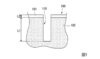
まず、第一工程において、図1に示すように、インプラントを設置する骨(対象骨)100に測定用の穴(測定穴)110を形成する。測定穴110は、少なくとも表層の皮質骨101を貫通して海綿骨102に達する深さであり、海綿骨102内における深さ寸法L1は、皮質骨内における深さ寸法L2の3倍以上に設定される。深さ寸法L1およびL2の和として示される測定穴110の総深さは、想定する埋入深さと同等とされるのが好ましい。一例を示すと、測定穴の大きさは、径として4ミリメートル(mm)より大きく10mm以下、あるいは5mm以上10mm以下程度、深さとして10mmより大きく80mm以下、あるいは15mm以上80mm以下程度である。
手術中にインプラントを設置する際に形成されるガイド穴や、タップによるネジ溝形成を行う前の下穴等を測定穴として用いてもよい。
First, in the first step, as shown in FIG. 1, a measurement hole (measurement hole) 110 is formed in a bone (target bone) 100 where an implant is to be installed. The
A guide hole formed when an implant is installed during surgery, a pilot hole before thread formation by a tap, or the like may be used as a measurement hole.
続く第二工程において、図2に示すように、測定穴110に振動子11を備える測定体10を設置する。測定体10は、整形外科用インプラントに用いられるインプラント材料で形成されており、一定の剛性を有する。インプラント材料としては、例えば生体適合性を有する各種金属、各種合金、各種セラミックなどが挙げられる。したがって、測定体としては、設置されるインプラント自体を用いてもよいし、後述するような各種の整形外科治具等が用いられてもよい。インプラントとは別の測定体を用いる場合は、設置されるインプラントに用いられるインプラント材料と同一材料で形成された測定体を用いるのが好ましい。
In the subsequent second step, as shown in FIG. 2, the
測定体10は、測定穴110内において、軸線まわり方向への回転および深さ方向における進退のいずれも、小さな力では生じない程度に保持されるように設置される。このように測定体を設置できるよう、測定穴110の形状や寸法は、測定体10の外形と略同等とされるのが好ましい。
The
測定体10は、振動子11が測定穴110の外に位置するように対象骨100に設置される。振動子11としては、外部からエネルギーを加えることにより振動できるものであればよく、例えば磁石等を用いることができる。
The
続く第三工程において、振動子11を振動させると、振動子11が取り付けられた測定体10が振動する。例えば振動子11が磁石である場合、図3に示すように、振動子11に磁気パルスMpを照射することにより、非接触で振動子11を振動させることができる。
In the subsequent third step, when the
測定体10の振動数を取得し、取得された振動数に対して共振周波数解析を行うことにより、設置強度指標が得られる。
得られた設置強度指標は、対象骨100に対するインプラントの設置強度評価に利用することができる。
An installation strength index is obtained by acquiring the vibration frequency of the
The obtained installation strength index can be used to evaluate the installation strength of the implant with respect to the
第三工程により得られる設置強度指標の一つとして、ISQ(Implant Stability Quotient)が挙げられる。ISQは、取得した振動数F(Hz)を下記式(1)により変換することで得られる数値であり、歯科インプラントの設置強度を評価するための指標として確立されている。
(1)ISQ=−2.4×10⁻¹⁴×F4+7.1×10⁻¹⁰×F3−7.8×
10−6×F2+0.0445×F−37
One of the installation strength indexes obtained by the third step is ISQ (Impartment Stability Quotient). ISQ is a numerical value obtained by converting the acquired frequency F (Hz) by the following formula (1), and is established as an index for evaluating the installation strength of a dental implant.
(1) ISQ = −2.4 × 10 −14 × F 4 + 7.1 × 10 −10 × F 3 −7.8 ×
10 −6 × F 2 + 0.0445 × F-37
発明者の検討では、振動子11としてのネオジム磁石(円柱型、直径4mm、高さ2mm、磁化方向:高さ方向、表面磁束密度:345ミリテスラ(mT))を頭部に固定した椎弓根スクリュー(Pedicle Screw、以下「PS」と称する。)を測定体10として用いた検討において、取得した振動数に対する共振周波数解析で得られたISQは、従来指標である、埋入トルクおよび引き抜き強度のいずれとも良好な相関を示すことが確認されている。この検討は、引き抜き強度との相関を検討するため、模擬骨を用いて行っている。
振動子として円柱形状の磁石を用いる場合は、例えば、直径2〜6mm、高さ2〜4mm、表面磁束密度310〜410mTの範囲のものを好適に用いることができる。
In the inventor's study, a pedicle in which a neodymium magnet (cylindrical type, diameter 4 mm, height 2 mm, magnetization direction: height direction, surface magnetic flux density: 345 millitesla (mT)) as the
When a cylindrical magnet is used as the vibrator, for example, a magnet having a diameter of 2 to 6 mm, a height of 2 to 4 mm, and a surface magnetic flux density of 310 to 410 mT can be suitably used.
以上説明したように、本実施形態の評価方法によれば、測定穴110に設置した測定体10を、振動子11を介して振動させる。そして、取得した振動数に対して共振周波数解析を行うことにより、従来臨床では測定し得なかった引き抜き強度や、従来計測が煩雑であった埋入トルクと相関を示す設置強度指標を簡便に取得することができる。
その結果、例えば術中に設置強度指標を用いて設置強度を評価し、インプラントの埋め込み深さを調節する、埋め込むインプラントのサイズを決定する、埋め込みを行うか否かを決定する等の種々の臨床判断の参考とすることができる。
As described above, according to the evaluation method of the present embodiment, the
As a result, various clinical judgments such as, for example, evaluating the installation strength using the installation strength index during the operation, adjusting the implant depth, determining the size of the implant to be implanted, and whether or not to perform the implantation, etc. It can be used as a reference.
さらに、発明者の検討では、測定体10を用いて取得したISQには、インプラントの周囲における対象骨の骨密度を反映している傾向が認められているため、埋入トルクや引き抜き強度等の従来指標では得られない情報が含まれていると考えられる。また、埋入トルクや引き抜き強度が、インプラントを刺入方向に引き抜いた際の力のみを反映しているのに対し、ISQはその仕組み上、インプラントを、実際に体内にてインプラントに作用すると思われる方向である、刺入方向と直交する方向に押し倒す力を反映している。これらの観点からは、本発明で取得される設置強度指標は、インプラントの設置強度を評価するにあたり、従来の埋入トルクや引き抜き強度よりも、より適切な指標であると言える。
したがって、適切なカットオフ値を設けるなどして取得された設置強度指標を適切に評価することにより、より正確な設置強度評価に貢献することができる。
Furthermore, in the inventor's study, the ISQ obtained using the measuring
Therefore, it is possible to contribute to more accurate installation strength evaluation by appropriately evaluating the installation strength index obtained by providing an appropriate cut-off value.
次に、本発明の第二実施形態について、図4から図6を参照して説明する。第二実施形態以降では、第一実施形態で説明した評価方法に好適に用いることができるインプラントや整形外科治具について説明する。以降の説明において、既に説明したものと共通する要素については、同一の符号を付して重複する説明を省略する。 Next, a second embodiment of the present invention will be described with reference to FIGS. In the second and subsequent embodiments, implants and orthopedic jigs that can be suitably used for the evaluation method described in the first embodiment will be described. In the following description, elements that are the same as those already described are denoted by the same reference numerals and redundant description is omitted.
図4に、本実施形態の整形外科用インプラント20を示す。インプラント20は、インプラント材料で形成され、測定体として用いられるPS(本体)21と、PS21の外面上に直接固定された振動子11とを備えている。
PS21の外形は、一般的なPSと同様であり、対象骨100内に埋め込まれるネジ部22と、ネジ部22に接続された頭部23とを備えている。頭部23には、脊椎固定のためのロッドが挿通される横穴23aが形成されている。ネオジム磁石からなる振動子11は、頭部23の外周面上に固定されている。
FIG. 4 shows an
The external shape of the
インプラント20を用いて上述の評価方法を実行する場合は、第一工程において、タップでネジ溝を形成した埋め込み用の穴を測定穴とし、第二工程においてこの埋め込み用穴にインプラント20を仮設置すればよい。仮設置は、想定している埋め込み深さまでネジ部22を埋め込んで行ってもよいし、想定している埋め込み深さより浅い位置までの埋め込みとしてもよい。
When the above-described evaluation method is executed using the
本実施形態のインプラント20では、振動子11が測定体であるPS21の外面に直接固定されているため、PS21が振動子11により精度よく振動される。
In the
インプラント20において、振動子の固定態様は様々に変更できる。図5に示す変形例のインプラント20Aでは、円柱状の振動子12の軸線がPS21の長手方向と平行になるように配置されている。振動子12が磁石であり、磁化方向が円柱形状の高さ方向である場合、インプラント20Aの振動子12に磁気パルスを照射すると、PS21は、自身の長手方向に往復振動する。
このようにすると、インプラントの深さ方向における設置強度を評価することができる。
In the
In this way, the installation strength in the depth direction of the implant can be evaluated.
図6に示す変形例のインプラント20Bでは、2つの振動子のうち、一方の振動子12AがPS21の長手方向と平行に取り付けられ、他方の振動子12Bは、自身の軸線がPS21の長手方向と直角をなすように配置されている。
In the
振動子12Aと12Bの磁化方向が同様である場合、インプラント20Bでは、第三工程において、磁気パルスがいずれの振動子に照射されるかにより、振動する方向が変化する。したがって、PS21を所望の方向に振動させて、所望の方向における設置強度を評価することができる。
When the magnetization directions of the
インプラントが埋め込まれる骨組織は、通常、骨密度を始めとする各種パラメータにおいて均一ではない。したがって、設置強度が異方性を有する可能性も当然に存在するが、このような場合でも、インプラント20Bを用いれば、複数の方向における設置強度を評価し、より詳細に臨床的判断を行う助けとすることができる。
なお、上述したいずれのインプラントにおいても、PS21を軸線まわりに所望の回転角度回して振動子の位置を変更すれば、より多くの方向における設置強度指標を取得し、より詳細に設置強度の異方性を評価することができる。
The bone tissue in which the implant is implanted is usually not uniform in various parameters including bone density. Therefore, there is a possibility that the installation strength has anisotropy, but even in such a case, the use of the
In any of the above-described implants, if the position of the vibrator is changed by rotating the
インプラント20のさらに他の変形例を示す。図7は、変形例のインプラント20Cを示す部分拡大断面図である。インプラント20Cを構成するPS31は、ネジ部32と頭部33とが、公知のボールジョイント構造で連結されて構成されている。これにより、インプラント20Cは、ネジ部32と頭部33に形成された横穴33aの軸線とがなす角度を調節可能に構成されており、ロッドの配置態様に応じた調節が可能である。
Another modification of the
ネジ部32と頭部33とは、ボールジョイント構造により相対移動可能であるため、このままでは一つの測定体として機能しない。しかし、頭部33の内周面に形成されたネジ溝33bに、振動子11が取り付けられた振動子部34をネジ嵌合させて、ネジ部32基端の球部32aを、頭部33においてネジ部32が突出する開口33cに向かって押圧すると、ネジ部32と頭部33とが相対移動できないように固定される。すなわち、PS31に振動子部34を締め込み固定することにより、ネジ部32および頭部33を有するPS31は、一体に振動する測定体として機能する。
Since the
したがって、インプラント20Cを用いて設置強度評価を行う場合は、振動子部34を締め込んだ状態で測定穴に仮設置し、設置強度評価取得後に振動子部34を取り外すことで、ロッドを好適に取り付けることができる。
また、振動子部34が磁石を有して構成される場合、設置強度評価終了後に振動子部34を取り外すことにより、術後のMRI検査も支障なく行うことができる。
Therefore, when the installation strength evaluation is performed using the implant 20C, the
Further, when the
本発明の第三実施形態について、図8および図9を参照して説明する。
図8に示す本実施形態のインプラント40は、インプラント材料で形成された剛体である金属製のカップ(本体、測定体)41を備える。カップ41は、人工股関節置換術において、ステム側のボール状部位を受けるために寛骨に埋め込まれるインプラントである。
A third embodiment of the present invention will be described with reference to FIGS.
The
インプラント40において、振動子11を備える振動子部42は、ステムを受ける凹面41aから突出するように設けられている。図9に示すように、振動子部42の基部(脆弱部)42aは、例えば溝を形成する等により他の部位よりも細く脆弱にされており、術者が手で折ることができるように構成されている。
In the
上記のように構成されたインプラント40の使用時の動作について説明する。
寛骨にカップ41を埋め込むための下穴を形成した後、術者は、図9に示すように、カップ41の凸面41bを、対象骨である寛骨Ac側に向けて下穴に接触させる。そして、インプラント40を保持しながら、インパクター50をインプラント40に押し当て、インパクター50越しに図示しないハンマーでインプラント40に衝撃を与え、下穴に打ち込んでいく。インパクター50において、インプラント40に押し当てられる先端側は筒状に形成されているため、振動子部42と干渉することなくインプラントを打ち込むことが可能である。
Operation during use of the
After forming the prepared hole for embedding the
インプラント40が想定量埋め込まれたとき、或いはその手前の任意のタイミングで、振動子11を振動させて上述の評価方法を実行すると、その時点におけるインプラント40の設置強度指標を取得することができる。術者は、取得された設置強度指標に基づき、打ち込みを追加するか、終了するか等の判断を行うことができる。
When the above-described evaluation method is executed by vibrating the
打ち込みが終了したら、術者は基部42aに力を加えて振動子部42を折り、カップ41から除去する。これにより、寛骨Acにはカップ41が残留し、かつ凹面41a上に突出する構造物も無くなるため、その後の手技を円滑に行うことができる。
When the driving is finished, the operator applies a force to the
以上説明したように、本実施形態のインプラント40においても、振動子11により測定体としてのカップ41を振動させて好適に本発明の評価方法を実行することができる。
As described above, also in the
また、先端側が筒状に形成されたインパクター50を用いることで、振動子部42を取り外さなくてもインプラント40の打ち込みが可能であるため、置換術の手技を煩雑にすることなく評価方法を実行することができる。
さらに、振動子部42は基部42aを折るだけでカップ41から除去できるため、振動子の取り外しを簡便に行うことができる。
In addition, since the
Furthermore, since the
以上、本発明のインプラントの諸態様について説明してきたが、本発明のインプラントは、上述したものには限定されない。たとえば、人工膝関節置換術において脛骨に埋め込まれるインプラントにも、上述の構成を適用することが可能である。 As mentioned above, although the aspect of the implant of this invention has been demonstrated, the implant of this invention is not limited to what was mentioned above. For example, the above-described configuration can be applied to an implant that is implanted in a tibia in a knee replacement.
次に、本発明の第四実施形態について、図10を参照して説明する。本実施形態では、本発明の評価方法に好適に用いることができる整形外科治具について説明する。 Next, a fourth embodiment of the present invention will be described with reference to FIG. In the present embodiment, an orthopedic jig that can be suitably used in the evaluation method of the present invention will be described.
図10に、本実施形態の整形外科治具であるプローべ60を示す。プローベ60は、インプラント材料で形成され、測定体として用いられる金属製の本体61と、本体61の一端に設けられた把持部62と、本体に取り付けられた振動子63とを備えている。本体61および把持部62については、公知の整形外科用プローベの各種構成を適宜選択して採用することができる。
FIG. 10 shows a
振動子63は、四角柱形状であることを除き、上述の振動子11と同様の構成を有する。四角柱形状は一例であり、他の形状であっても何ら問題はない。
The
PSの設置前には、予備的に形成した下穴にプローベを差し込んでプロービングを行うことがある。振動子を備えた本実施形態のプローベ60を用いると、下穴を測定穴として、差し込んだプローべ60の本体61を振動させることにより、PSの設置前に設置強度指標を取得することが可能である。したがって、取得された設置強度指標を参考に、適切なサイズのPSを選択する等に貢献することができる。
Before installing the PS, the probe may be inserted into a pre-formed pilot hole for probing. When the
また、整形外科治具に振動子を取りつけると、インプラントに振動子を設けずに本発明の評価方法を実行することができるため、インプラントから振動子を取り外す等の作業が必要ない。さらに、整形外科治具から振動子を取り外す必要もないため、さらに簡便に評価方法を実行できる。
整形外科治具を用いて取得される設置前の設置強度指標と、実際に設置されたインプラントから取得される設置強度指標を使い分けることで、様々なケースにおいて最適な設置強度評価を行うことが可能になる。
In addition, when the vibrator is attached to the orthopedic jig, the evaluation method of the present invention can be executed without providing the vibrator on the implant, and therefore, an operation such as removing the vibrator from the implant is not necessary. Furthermore, since it is not necessary to remove the transducer from the orthopedic jig, the evaluation method can be executed more simply.
It is possible to perform optimal installation strength evaluation in various cases by using properly the installation strength index obtained before installation using the orthopedic jig and the installation strength index acquired from the actually installed implant. become.
本発明において、振動子を設ける整形外科治具は、上述のプローベには限られない。例えば、図11に示すように、下穴にPS設置用のネジ溝を形成するためのタップ70における、インプラント材料で形成された本体71に振動子63を設けてもよい。この場合は、下穴にタップ70をねじ込んでネジ溝を形成したあと、そのままの状態で本体71を振動させて設置強度指標を取得することができる。
In the present invention, the orthopedic jig provided with the vibrator is not limited to the probe described above. For example, as shown in FIG. 11, a
また、整形外科治具に振動子を設ける場合、図12に模式的に示す変形例のプローベ60Aのように、振動子65を振動させる振動源66を本体61に設けてもよい。このようにすると、振動子65を振動させるためのパルス等を外部から与える必要がなく、例えば、振動源66を作動させるスイッチ66aを押すだけで、測定穴に設置した本体62を簡便に駆動することができる。
さらに、図12に示すように、取得した振動数を記憶する記憶媒体等を含む記憶部67、振動数に対して共振周波数解析を行うICチップ等を含む解析部68、取得された設置強度指標等を表示する液晶ディスプレイ等を含む表示部69等を備えた構成であれば、測定穴への設置から設置強度指標取得までの一連の作業を極めて簡便に行い、手技中の各種判断を迅速かつ好適に行うことに貢献することができる。
上述した記憶部、解析部、表示部等は、整形外科治具に直接設けられなくてもよい。例えば、コンピュータと整形外科治具を有線または無線で通信可能に構成し、このコンピュータを記憶部、解析部、表示部等として機能させてもよい。
Further, when the vibrator is provided in the orthopedic jig, a
Furthermore, as shown in FIG. 12, a
The storage unit, analysis unit, display unit, and the like described above may not be provided directly on the orthopedic jig. For example, the computer and the orthopedic jig may be configured to be able to communicate with each other by wire or wirelessly, and the computer may function as a storage unit, an analysis unit, a display unit, or the like.
以上、本発明の各実施形態について説明したが、本発明の技術範囲は上記実施形態に限定されるものではなく、本発明の趣旨を逸脱しない範囲において構成要素の組み合わせを変えたり、各構成要素に種々の変更を加えたり、削除したりすることが可能である。 The embodiments of the present invention have been described above. However, the technical scope of the present invention is not limited to the above-described embodiments, and combinations of components or components may be changed without departing from the spirit of the present invention. It is possible to make various changes to or delete them.
例えば、本発明の評価方法において、測定穴に設置した測定体を振動させる方法は上述した磁力によるものには限られない。例えば測定体に超音波振動子が取り付けられ、超音波により測定体が振動されてもよい。
この他、測定体に直接衝撃を与えて振動させる方法も可能ではあるが、この方法では対象骨に過剰な負荷がかかる可能性があるため、磁力や超音波等により非接触で測定体を振動させる方法が好ましい。
For example, in the evaluation method of the present invention, the method of vibrating the measurement body installed in the measurement hole is not limited to the above-described magnetic force. For example, an ultrasonic transducer may be attached to the measurement body, and the measurement body may be vibrated by ultrasonic waves.
In addition, it is possible to vibrate by directly impacting the measurement object, but this method may apply an excessive load to the target bone, so the measurement object is vibrated in a non-contact manner by magnetic force or ultrasonic waves. The method of making it preferable is.
10 測定体
11、12、12A、12B、63、65 振動子
20、20A、20B、20C、40 整形外科用インプラント
21、31 椎弓根スクリュー(本体)
34、42 振動子部
41 カップ(本体)
42a 基部(脆弱部)
60、60A プローベ(整形外科治具)
61 本体
70 タップ(整形外科治具)
71 本体
100 対象骨
101 皮質骨
102 海綿骨
110 測定穴
Ac 寛骨(対象骨)
10
34, 42
42a Base (fragile)
60, 60A probe (orthopedic jig)
61
71
Claims (9)
前記測定穴にインプラント材料で形成された測定体を設置する第二工程と、
前記測定体を振動させて振動数を取得し、前記振動数に対して共振周波数解析を実行する第三工程と、
を備える、
整形外科用インプラントの設置強度評価方法。 A first step of forming a measurement hole in the target bone;
A second step of installing a measurement body formed of an implant material in the measurement hole;
Vibrating the measuring body to obtain a frequency, and performing a resonance frequency analysis on the frequency; and
Comprising
A method for evaluating the installation strength of an orthopedic implant.
前記第三工程において、前記振動子が非接触で振動される、
請求項1または2に記載の整形外科用インプラントの設置強度評価方法。 A vibrator is provided on the measurement body,
In the third step, the vibrator is vibrated without contact.
The installation strength evaluation method of the orthopedic implant of Claim 1 or 2.
前記本体に取り付けられた振動子と、
を備える整形外科用インプラント。 A body formed of an implant material;
A vibrator attached to the main body;
An orthopedic implant comprising:
前記本体に取り付けられた振動子と、
を備える、
整形外科治具。 A body formed of an implant material;
A vibrator attached to the main body;
Comprising
Orthopedic jig.
Priority Applications (1)
| Application Number | Priority Date | Filing Date | Title |
|---|---|---|---|
| JP2016028225A JP2017144061A (en) | 2016-02-17 | 2016-02-17 | Method for evaluating installation strength of orthopedic implant, orthopedic implant, and orthopedic jig |
Applications Claiming Priority (1)
| Application Number | Priority Date | Filing Date | Title |
|---|---|---|---|
| JP2016028225A JP2017144061A (en) | 2016-02-17 | 2016-02-17 | Method for evaluating installation strength of orthopedic implant, orthopedic implant, and orthopedic jig |
Publications (1)
| Publication Number | Publication Date |
|---|---|
| JP2017144061A true JP2017144061A (en) | 2017-08-24 |
Family
ID=59681022
Family Applications (1)
| Application Number | Title | Priority Date | Filing Date |
|---|---|---|---|
| JP2016028225A Pending JP2017144061A (en) | 2016-02-17 | 2016-02-17 | Method for evaluating installation strength of orthopedic implant, orthopedic implant, and orthopedic jig |
Country Status (1)
| Country | Link |
|---|---|
| JP (1) | JP2017144061A (en) |
Cited By (2)
| Publication number | Priority date | Publication date | Assignee | Title |
|---|---|---|---|---|
| WO2019054442A1 (en) * | 2017-09-14 | 2019-03-21 | 学校法人慶應義塾 | Implant installation strength evaluation method, implant installation strength evaluation device, and program |
| CN110464352A (en) * | 2019-07-29 | 2019-11-19 | 上海联影医疗科技有限公司 | Image scanning parameter determination method, device and MRI scan method |
Citations (3)
| Publication number | Priority date | Publication date | Assignee | Title |
|---|---|---|---|---|
| JP2003524475A (en) * | 1999-09-16 | 2003-08-19 | インテグレイシヨン・ダイアグノステイツクス・リミテツド | Method and apparatus for establishing implant or unit stability |
| JP2006527627A (en) * | 2003-06-19 | 2006-12-07 | インテグレイシヨン・ダイアグノステイツクス・リミテツド | Method and apparatus for testing an object |
| US20090092945A1 (en) * | 2007-10-05 | 2009-04-09 | National Applied Research Laboratories | Non-contact apparatus and method for stability assessment of dental implant |
-
2016
- 2016-02-17 JP JP2016028225A patent/JP2017144061A/en active Pending
Patent Citations (3)
| Publication number | Priority date | Publication date | Assignee | Title |
|---|---|---|---|---|
| JP2003524475A (en) * | 1999-09-16 | 2003-08-19 | インテグレイシヨン・ダイアグノステイツクス・リミテツド | Method and apparatus for establishing implant or unit stability |
| JP2006527627A (en) * | 2003-06-19 | 2006-12-07 | インテグレイシヨン・ダイアグノステイツクス・リミテツド | Method and apparatus for testing an object |
| US20090092945A1 (en) * | 2007-10-05 | 2009-04-09 | National Applied Research Laboratories | Non-contact apparatus and method for stability assessment of dental implant |
Cited By (9)
| Publication number | Priority date | Publication date | Assignee | Title |
|---|---|---|---|---|
| WO2019054442A1 (en) * | 2017-09-14 | 2019-03-21 | 学校法人慶應義塾 | Implant installation strength evaluation method, implant installation strength evaluation device, and program |
| CN111093556A (en) * | 2017-09-14 | 2020-05-01 | 学校法人庆应义塾 | Implant installation strength evaluation method, implant installation strength evaluation device, and program |
| JPWO2019054442A1 (en) * | 2017-09-14 | 2020-10-15 | 学校法人慶應義塾 | Implant installation strength evaluation method, implant installation strength evaluation device, and program |
| EP3682842A4 (en) * | 2017-09-14 | 2021-06-09 | Keio University | Implant installation strength evaluation method, implant installation strength evaluation device, and program |
| CN111093556B (en) * | 2017-09-14 | 2022-08-16 | 学校法人庆应义塾 | Implant installation strength evaluation device and recording medium |
| JP7281770B2 (en) | 2017-09-14 | 2023-05-26 | 慶應義塾 | IMPLANT INSTALLATION STRENGTH EVALUATION METHOD, IMPLANT INSTALLATION STRENGTH EVALUATION DEVICE, AND PROGRAM |
| US11737705B2 (en) | 2017-09-14 | 2023-08-29 | Keio University | Implant installation strength evaluation method, implant installation strength evaluation device, and program |
| CN110464352A (en) * | 2019-07-29 | 2019-11-19 | 上海联影医疗科技有限公司 | Image scanning parameter determination method, device and MRI scan method |
| CN110464352B (en) * | 2019-07-29 | 2023-12-22 | 上海联影医疗科技股份有限公司 | Imaging scanning parameter determining method and device and magnetic resonance imaging scanning method |
Similar Documents
| Publication | Publication Date | Title |
|---|---|---|
| US10426541B2 (en) | Device for assisting with the placement of an orthopedic instrument | |
| US10849766B2 (en) | Implant evaluation in prosthesis installation | |
| US11191517B2 (en) | Invasive sense measurement in prosthesis installation | |
| US10912655B2 (en) | Force sense measurement in prosthesis installation | |
| EP3046514B1 (en) | Patient specific bone preparation for consistent effective fixation feature engagement | |
| Mathieu et al. | Variation of the impact duration during the in vitro insertion of acetabular cup implants | |
| Varini et al. | Assessment of implant stability of cementless hip prostheses through the frequency response function of the stem–bone system | |
| JP2014502183A (en) | A system for determining the quality of an individual's bone structure | |
| Lannocca et al. | Intra-operative evaluation of cementless hip implant stability: A prototype device based on vibration analysis | |
| JP7240404B2 (en) | Device for inserting surgical graft material | |
| Cairns et al. | Ability of modal analysis to detect osseointegration of implants in transfemoral amputees: a physical model study | |
| JP2017144061A (en) | Method for evaluating installation strength of orthopedic implant, orthopedic implant, and orthopedic jig | |
| Karnik et al. | A mathematical model for biomechanical evaluation of micro-motion in dental prosthetics using vibroacoustic RFA | |
| CN111093556B (en) | Implant installation strength evaluation device and recording medium | |
| US11331069B2 (en) | Invasive sense measurement in prosthesis installation | |
| Pitzen et al. | Insertion torque and pullout force of rescue screws for anterior cervical plate fixation in a fatigued initial pilot hole | |
| Shetty et al. | Comparison of the primary stability achieved by using dental implants with variable thread designs when placed using different drilling techniques. An in vitro bone modular analysis | |
| JP7059287B2 (en) | probe | |
| Pitzen et al. | Effectiveness of cemented rescue screws for anterior cervical plate fixation | |
| JP2020536705A (en) | Devices, assembly parts and methods for inserting surgical implant materials | |
| Abed et al. | Testing mechanical behaviour of bone-plate construct | |
| JP2008539879A (en) | Implantable miniature ultrasonic transducer | |
| Pezowicz et al. | Influence of loading history on the cervical screw pullout strength value | |
| Harirforoush | Dental implant stability analysis by using resonance frequency method | |
| Leuridan et al. | Vibrational techniques to assess the initial stability of spherical press-fitted implants: in vitro study |
Legal Events
| Date | Code | Title | Description |
|---|---|---|---|
| A521 | Request for written amendment filed |
Free format text: JAPANESE INTERMEDIATE CODE: A523 Effective date: 20160519 |
|
| A621 | Written request for application examination |
Free format text: JAPANESE INTERMEDIATE CODE: A621 Effective date: 20190201 |
|
| A977 | Report on retrieval |
Free format text: JAPANESE INTERMEDIATE CODE: A971007 Effective date: 20191021 |
|
| A131 | Notification of reasons for refusal |
Free format text: JAPANESE INTERMEDIATE CODE: A131 Effective date: 20191029 |
|
| A601 | Written request for extension of time |
Free format text: JAPANESE INTERMEDIATE CODE: A601 Effective date: 20191217 |
|
| A521 | Request for written amendment filed |
Free format text: JAPANESE INTERMEDIATE CODE: A523 Effective date: 20200227 |
|
| A02 | Decision of refusal |
Free format text: JAPANESE INTERMEDIATE CODE: A02 Effective date: 20200728 |