JP4806012B2 - Method and apparatus for controlling the operating system of a gas turbine combustion chamber - Google Patents
Method and apparatus for controlling the operating system of a gas turbine combustion chamber Download PDFInfo
- Publication number
- JP4806012B2 JP4806012B2 JP2008510571A JP2008510571A JP4806012B2 JP 4806012 B2 JP4806012 B2 JP 4806012B2 JP 2008510571 A JP2008510571 A JP 2008510571A JP 2008510571 A JP2008510571 A JP 2008510571A JP 4806012 B2 JP4806012 B2 JP 4806012B2
- Authority
- JP
- Japan
- Prior art keywords
- amount
- control
- combustion chamber
- control device
- controller
- Prior art date
- Legal status (The legal status is an assumption and is not a legal conclusion. Google has not performed a legal analysis and makes no representation as to the accuracy of the status listed.)
- Active
Links
Images

Classifications
-
- F—MECHANICAL ENGINEERING; LIGHTING; HEATING; WEAPONS; BLASTING
- F23—COMBUSTION APPARATUS; COMBUSTION PROCESSES
- F23R—GENERATING COMBUSTION PRODUCTS OF HIGH PRESSURE OR HIGH VELOCITY, e.g. GAS-TURBINE COMBUSTION CHAMBERS
- F23R3/00—Continuous combustion chambers using liquid or gaseous fuel
- F23R3/28—Continuous combustion chambers using liquid or gaseous fuel characterised by the fuel supply
- F23R3/34—Feeding into different combustion zones
- F23R3/343—Pilot flames, i.e. fuel nozzles or injectors using only a very small proportion of the total fuel to insure continuous combustion
-
- F—MECHANICAL ENGINEERING; LIGHTING; HEATING; WEAPONS; BLASTING
- F02—COMBUSTION ENGINES; HOT-GAS OR COMBUSTION-PRODUCT ENGINE PLANTS
- F02C—GAS-TURBINE PLANTS; AIR INTAKES FOR JET-PROPULSION PLANTS; CONTROLLING FUEL SUPPLY IN AIR-BREATHING JET-PROPULSION PLANTS
- F02C9/00—Controlling gas-turbine plants; Controlling fuel supply in air- breathing jet-propulsion plants
- F02C9/26—Control of fuel supply
- F02C9/28—Regulating systems responsive to plant or ambient parameters, e.g. temperature, pressure, rotor speed
-
- F—MECHANICAL ENGINEERING; LIGHTING; HEATING; WEAPONS; BLASTING
- F02—COMBUSTION ENGINES; HOT-GAS OR COMBUSTION-PRODUCT ENGINE PLANTS
- F02C—GAS-TURBINE PLANTS; AIR INTAKES FOR JET-PROPULSION PLANTS; CONTROLLING FUEL SUPPLY IN AIR-BREATHING JET-PROPULSION PLANTS
- F02C9/00—Controlling gas-turbine plants; Controlling fuel supply in air- breathing jet-propulsion plants
- F02C9/48—Control of fuel supply conjointly with another control of the plant
- F02C9/50—Control of fuel supply conjointly with another control of the plant with control of working fluid flow
- F02C9/54—Control of fuel supply conjointly with another control of the plant with control of working fluid flow by throttling the working fluid, by adjusting vanes
-
- F—MECHANICAL ENGINEERING; LIGHTING; HEATING; WEAPONS; BLASTING
- F23—COMBUSTION APPARATUS; COMBUSTION PROCESSES
- F23N—REGULATING OR CONTROLLING COMBUSTION
- F23N1/00—Regulating fuel supply
- F23N1/02—Regulating fuel supply conjointly with air supply
-
- F—MECHANICAL ENGINEERING; LIGHTING; HEATING; WEAPONS; BLASTING
- F23—COMBUSTION APPARATUS; COMBUSTION PROCESSES
- F23N—REGULATING OR CONTROLLING COMBUSTION
- F23N5/00—Systems for controlling combustion
- F23N5/02—Systems for controlling combustion using devices responsive to thermal changes or to thermal expansion of a medium
-
- F—MECHANICAL ENGINEERING; LIGHTING; HEATING; WEAPONS; BLASTING
- F23—COMBUSTION APPARATUS; COMBUSTION PROCESSES
- F23N—REGULATING OR CONTROLLING COMBUSTION
- F23N5/00—Systems for controlling combustion
- F23N5/16—Systems for controlling combustion using noise-sensitive detectors
-
- F—MECHANICAL ENGINEERING; LIGHTING; HEATING; WEAPONS; BLASTING
- F23—COMBUSTION APPARATUS; COMBUSTION PROCESSES
- F23R—GENERATING COMBUSTION PRODUCTS OF HIGH PRESSURE OR HIGH VELOCITY, e.g. GAS-TURBINE COMBUSTION CHAMBERS
- F23R3/00—Continuous combustion chambers using liquid or gaseous fuel
- F23R3/02—Continuous combustion chambers using liquid or gaseous fuel characterised by the air-flow or gas-flow configuration
- F23R3/26—Controlling the air flow
-
- F—MECHANICAL ENGINEERING; LIGHTING; HEATING; WEAPONS; BLASTING
- F05—INDEXING SCHEMES RELATING TO ENGINES OR PUMPS IN VARIOUS SUBCLASSES OF CLASSES F01-F04
- F05D—INDEXING SCHEME FOR ASPECTS RELATING TO NON-POSITIVE-DISPLACEMENT MACHINES OR ENGINES, GAS-TURBINES OR JET-PROPULSION PLANTS
- F05D2270/00—Control
- F05D2270/01—Purpose of the control system
- F05D2270/08—Purpose of the control system to produce clean exhaust gases
- F05D2270/082—Purpose of the control system to produce clean exhaust gases with as little NOx as possible
-
- F—MECHANICAL ENGINEERING; LIGHTING; HEATING; WEAPONS; BLASTING
- F05—INDEXING SCHEMES RELATING TO ENGINES OR PUMPS IN VARIOUS SUBCLASSES OF CLASSES F01-F04
- F05D—INDEXING SCHEME FOR ASPECTS RELATING TO NON-POSITIVE-DISPLACEMENT MACHINES OR ENGINES, GAS-TURBINES OR JET-PROPULSION PLANTS
- F05D2270/00—Control
- F05D2270/01—Purpose of the control system
- F05D2270/08—Purpose of the control system to produce clean exhaust gases
- F05D2270/083—Purpose of the control system to produce clean exhaust gases by monitoring combustion conditions
-
- F—MECHANICAL ENGINEERING; LIGHTING; HEATING; WEAPONS; BLASTING
- F05—INDEXING SCHEMES RELATING TO ENGINES OR PUMPS IN VARIOUS SUBCLASSES OF CLASSES F01-F04
- F05D—INDEXING SCHEME FOR ASPECTS RELATING TO NON-POSITIVE-DISPLACEMENT MACHINES OR ENGINES, GAS-TURBINES OR JET-PROPULSION PLANTS
- F05D2270/00—Control
- F05D2270/01—Purpose of the control system
- F05D2270/14—Purpose of the control system to control thermoacoustic behaviour in the combustion chambers
-
- F—MECHANICAL ENGINEERING; LIGHTING; HEATING; WEAPONS; BLASTING
- F05—INDEXING SCHEMES RELATING TO ENGINES OR PUMPS IN VARIOUS SUBCLASSES OF CLASSES F01-F04
- F05D—INDEXING SCHEME FOR ASPECTS RELATING TO NON-POSITIVE-DISPLACEMENT MACHINES OR ENGINES, GAS-TURBINES OR JET-PROPULSION PLANTS
- F05D2270/00—Control
- F05D2270/30—Control parameters, e.g. input parameters
- F05D2270/303—Temperature
-
- F—MECHANICAL ENGINEERING; LIGHTING; HEATING; WEAPONS; BLASTING
- F05—INDEXING SCHEMES RELATING TO ENGINES OR PUMPS IN VARIOUS SUBCLASSES OF CLASSES F01-F04
- F05D—INDEXING SCHEME FOR ASPECTS RELATING TO NON-POSITIVE-DISPLACEMENT MACHINES OR ENGINES, GAS-TURBINES OR JET-PROPULSION PLANTS
- F05D2270/00—Control
- F05D2270/70—Type of control algorithm
- F05D2270/707—Type of control algorithm fuzzy logic
-
- F—MECHANICAL ENGINEERING; LIGHTING; HEATING; WEAPONS; BLASTING
- F05—INDEXING SCHEMES RELATING TO ENGINES OR PUMPS IN VARIOUS SUBCLASSES OF CLASSES F01-F04
- F05D—INDEXING SCHEME FOR ASPECTS RELATING TO NON-POSITIVE-DISPLACEMENT MACHINES OR ENGINES, GAS-TURBINES OR JET-PROPULSION PLANTS
- F05D2270/00—Control
- F05D2270/70—Type of control algorithm
- F05D2270/709—Type of control algorithm with neural networks
-
- F—MECHANICAL ENGINEERING; LIGHTING; HEATING; WEAPONS; BLASTING
- F23—COMBUSTION APPARATUS; COMBUSTION PROCESSES
- F23N—REGULATING OR CONTROLLING COMBUSTION
- F23N2223/00—Signal processing; Details thereof
- F23N2223/14—Differentiation
-
- F—MECHANICAL ENGINEERING; LIGHTING; HEATING; WEAPONS; BLASTING
- F23—COMBUSTION APPARATUS; COMBUSTION PROCESSES
- F23N—REGULATING OR CONTROLLING COMBUSTION
- F23N2223/00—Signal processing; Details thereof
- F23N2223/48—Learning / Adaptive control
-
- F—MECHANICAL ENGINEERING; LIGHTING; HEATING; WEAPONS; BLASTING
- F23—COMBUSTION APPARATUS; COMBUSTION PROCESSES
- F23N—REGULATING OR CONTROLLING COMBUSTION
- F23N2223/00—Signal processing; Details thereof
- F23N2223/52—Fuzzy logic
-
- F—MECHANICAL ENGINEERING; LIGHTING; HEATING; WEAPONS; BLASTING
- F23—COMBUSTION APPARATUS; COMBUSTION PROCESSES
- F23N—REGULATING OR CONTROLLING COMBUSTION
- F23N2225/00—Measuring
- F23N2225/04—Measuring pressure
-
- F—MECHANICAL ENGINEERING; LIGHTING; HEATING; WEAPONS; BLASTING
- F23—COMBUSTION APPARATUS; COMBUSTION PROCESSES
- F23N—REGULATING OR CONTROLLING COMBUSTION
- F23N2225/00—Measuring
- F23N2225/08—Measuring temperature
-
- F—MECHANICAL ENGINEERING; LIGHTING; HEATING; WEAPONS; BLASTING
- F23—COMBUSTION APPARATUS; COMBUSTION PROCESSES
- F23N—REGULATING OR CONTROLLING COMBUSTION
- F23N2231/00—Fail safe
- F23N2231/06—Fail safe for flame failures
- F23N2231/08—Fail safe for flame failures for pilot flame failures
-
- F—MECHANICAL ENGINEERING; LIGHTING; HEATING; WEAPONS; BLASTING
- F23—COMBUSTION APPARATUS; COMBUSTION PROCESSES
- F23N—REGULATING OR CONTROLLING COMBUSTION
- F23N2241/00—Applications
- F23N2241/20—Gas turbines
-
- F—MECHANICAL ENGINEERING; LIGHTING; HEATING; WEAPONS; BLASTING
- F23—COMBUSTION APPARATUS; COMBUSTION PROCESSES
- F23N—REGULATING OR CONTROLLING COMBUSTION
- F23N5/00—Systems for controlling combustion
- F23N5/003—Systems for controlling combustion using detectors sensitive to combustion gas properties
Description
本発明は、ガスタービン燃焼室の動作系を制御するための制御方法および制御装置に関する。 The present invention relates to a control method and a control apparatus for controlling an operation system of a gas turbine combustion chamber.
ガスタービンは、一般に圧縮機とタービンと燃焼室部とを含む流体機械である。圧縮機において吸い込まれた周囲空気が圧縮され、圧縮された空気は最後に燃焼室部に供給される。燃焼室部に配置される少なくとも1つの燃焼室が大抵複数のバーナを備えており、圧縮された空気がこれらのバーナに供給される。圧縮された空気の他にバーナにはさらに燃料が供給され、燃料は空気と混合され、燃焼させられる。その際に燃焼室内に発生する高温の燃焼ガスはタービンに供給され、そこで減圧され冷却され、タービンを回転させる。こうして燃焼ガスの熱エネルギーが機械的仕事に変換され、この機械的仕事は一方で圧縮機の駆動に利用され、他方で負荷、例えば電気を発生する発電機の駆動に利用される。 A gas turbine is a fluid machine that generally includes a compressor, a turbine, and a combustion chamber. The ambient air sucked in the compressor is compressed, and the compressed air is finally supplied to the combustion chamber. At least one combustion chamber arranged in the combustion chamber section is usually provided with a plurality of burners, and compressed air is supplied to these burners. In addition to the compressed air, the burner is further supplied with fuel, which is mixed with air and burned. At that time, the high-temperature combustion gas generated in the combustion chamber is supplied to the turbine, where it is decompressed and cooled to rotate the turbine. The thermal energy of the combustion gas is thus converted into mechanical work, which is used on the one hand for driving the compressor and on the other hand for driving a load, for example a generator for generating electricity.
燃焼室内での燃焼時には安定した火炎の存在することに注意しなければならない。火炎の不安定性は特に燃焼排気中の共振燃焼振動に基づいて現れ、一方で有害物質排出量増加をもたらすことがあり、他方で燃焼室の振動を引き起こすことがあり、振動は燃焼室の寿命を低下させ、整備間隔を短くする。 It should be noted that there is a stable flame when burning in the combustion chamber. Flame instability manifests itself in particular due to resonant combustion vibrations in the combustion exhaust, which can lead to increased emissions of harmful substances, on the other hand, can cause combustion chamber vibrations, which can reduce the life of the combustion chamber. Decrease and shorten the maintenance interval.
さらに、バーナはふつう主燃料供給部の他にいわゆるパイロット燃料供給部も装備している。主燃料質量流量と比較して僅かな燃料質量流量がパイロット燃料供給部を介して供給されて火炎を支える。それに加えて、必要なら、供給されるパイロット燃料の質量流量を調節することによって火炎は安定させることができる。 Furthermore, the burner is usually equipped with a so-called pilot fuel supply section in addition to the main fuel supply section. A small fuel mass flow compared to the main fuel mass flow is supplied via the pilot fuel supply to support the flame. In addition, if necessary, the flame can be stabilized by adjusting the mass flow rate of the supplied pilot fuel.
火炎の安定性は多数の外乱によって影響を受ける。このような外乱の例は周囲温度、燃料の密度および発熱量であるが、しかしガスタービン設備、特に燃焼室とバーナの構造状態でもある。外乱の影響はパイロットバーナを介して供給される燃料質量流量によって補償される。パイロットガス質量流量は特定の限界を上もしくは下に超えてはならない。というのも、さもないと火炎は不安定領域に移行するであろうからである。パイロットガス質量流量を安定した火炎領域に保つために、投入すべきパイロットガス質量流量を外乱に依存して規定する機能が応用される。この機能はパイロットガス曲線とも称される。 Flame stability is affected by numerous disturbances. Examples of such disturbances are ambient temperature, fuel density and calorific value, but also the structural state of gas turbine equipment, in particular combustion chambers and burners. The influence of the disturbance is compensated by the fuel mass flow supplied via the pilot burner. The pilot gas mass flow rate must not exceed a certain limit. Otherwise the flame will move to the unstable region. In order to keep the pilot gas mass flow rate in a stable flame region, a function for defining the pilot gas mass flow rate to be charged depending on the disturbance is applied. This function is also referred to as a pilot gas curve.
パイロットガス曲線には多数のガスタービンパラメータが含まれる。これらのパラメータは、ガスタービン設備が同一構造である場合でもガスタービン設備ごとに変化する。特に、ガスタービン設備の設置場所の周囲条件も考慮しなければならない。それに加えて、ガスタービン設備の運転時にガスタービンパラメータは時間とともに変化を受けることがある。そのことから、パイロットガス曲線の時間を要する新規調整または再調整が必要となることがある。調整プロセスによって高い費用および停止時間が引き起こされる。 The pilot gas curve includes a number of gas turbine parameters. These parameters vary for each gas turbine facility even when the gas turbine facility has the same structure. In particular, the ambient conditions of the installation location of the gas turbine equipment must be taken into account. In addition, gas turbine parameters may change over time during operation of the gas turbine installation. As a result, new adjustments or readjustments that require time for the pilot gas curve may be required. The adjustment process causes high costs and downtime.
パイロットガス曲線に対する外乱の影響が定量的に十分には分かっていないことがなお加わる。多くの外乱にはそもそも適切には反応することができない。 It is still added that the influence of the disturbance on the pilot gas curve is not fully understood quantitatively. Many disturbances cannot respond properly in the first place.
そこで本発明の課題は、火炎不安定性を防ぐのに有利に利用することのできる制御方法および制御装置を提供することである。 Therefore, an object of the present invention is to provide a control method and a control apparatus that can be advantageously used to prevent flame instability.
この課題は、請求項1による制御方法および請求項13による制御装置によって解決される。従属請求項は本発明の有利な諸構成を含む。
This problem is solved by a control method according to claim 1 and a control device according to
ガスタービン設備の動作系を制御するための本発明に係る制御方法では、少なくとも1つの制御量が検出され、検出された制御量が所定の基準量と比較され、この比較に基づいて少なくとも1つの操作量が算定される。算定された操作量は、ガスタービン設備の燃焼室への空気供給量および/または燃料供給量を調節する少なくとも1つの操作機構に対して出力される。その際、安定性限界への火炎の接近を演繹することのできる制御量が少なくとも1つの制御量として利用される。特に、少なくとも1つのバーナパラメータまたは1つの燃焼室パラメータの時間的変化がこのような制御量として考慮される。特に、燃焼室内の交番圧力および/または燃焼室加速度を燃焼室パラメータとして利用することができる。例えばバーナフランジの交番圧力をバーナパラメータとして利用することができる。 In the control method according to the present invention for controlling the operating system of the gas turbine equipment, at least one control amount is detected, the detected control amount is compared with a predetermined reference amount, and at least one control amount is based on this comparison. The manipulated variable is calculated. The calculated operation amount is output to at least one operation mechanism that adjusts the air supply amount and / or the fuel supply amount to the combustion chamber of the gas turbine equipment. In this case, a control amount that can deduce the approach of the flame to the stability limit is used as at least one control amount. In particular, the temporal variation of at least one burner parameter or one combustion chamber parameter is considered as such a controlled variable. In particular, alternating pressure in the combustion chamber and / or combustion chamber acceleration can be used as combustion chamber parameters. For example, the alternating pressure of the burner flange can be used as the burner parameter.
本発明に係る制御方法でもって、火炎安定性に対する外乱の影響が定量的に正確に既知である必要もなしに、火炎は安定保持することができる。 With the control method according to the present invention, the flame can be held stable without the need to know the influence of the disturbance on the flame stability quantitatively and accurately.
本発明は以下の新しいコンセプトに依拠している。先行技術におけるように外乱に目を向ける代わりに、火炎の安定性を維持するために、本発明に係る制御方法ではバーナ不安定限界、すなわち安定性限界自体に目を向ける。換言するなら、パイロットガス質量流量は検出された外乱に依存して変更されるのでなく、バーナ不安定限界に接近時に変更される。バーナ不安定限界に接近したことの確認は外乱の定量的知識なしに行われる。 The present invention relies on the following new concept. Instead of looking at disturbances as in the prior art, the control method according to the present invention looks at the burner instability limit, ie the stability limit itself, in order to maintain the stability of the flame. In other words, the pilot gas mass flow rate is not changed depending on the detected disturbance, but is changed when approaching the burner instability limit. Confirmation that the burner instability limit has been approached is made without quantitative knowledge of the disturbance.
先行技術において外乱の定量的知識が不可欠であるのは、外乱とともに変化するバーナ不安定限界を算定し、こうしてすべての外乱についてバーナ不安定限界の内部で動くパイロットガス曲線を提供できるようにするためにである。既に冒頭で述べたようにバーナ不安定限界に対する外乱の影響は同一構造のガスタービン設備の場合でも例えば周囲条件の違いに基づいて変化するので、先行技術では各ガスタービン設備の個別的調整が必要である。 Quantitative knowledge of disturbances is essential in the prior art in order to be able to calculate the burner instability limits that change with the disturbances, thus providing a pilot gas curve that moves within the burner instability limits for all disturbances. To. As already mentioned at the beginning, the influence of disturbance on the burner instability limit changes even in the case of gas turbine equipment of the same structure, for example, based on differences in ambient conditions, so the prior art requires individual adjustment of each gas turbine equipment It is.
それに対して本発明に係る方法では、外乱とバーナ不安定限界の状態との関係の定量的知識は不可欠ではない。というのも、火炎を安定させるためのパイロットガス量の変更はバーナ不安定限界への接近が起きたか否か、およびバーナ不安定限界への接近の直接的検出が行われたか否かに直接依存させることができるからである。それに加えて、パイロットガスはさらに火炎を支持するのにも利用される。 On the other hand, in the method according to the present invention, quantitative knowledge of the relationship between the disturbance and the state of the burner instability limit is not essential. This is because the change in the pilot gas amount to stabilize the flame is directly dependent on whether an approach to the burner instability limit has occurred and whether an approach to the burner instability limit has been directly detected. It is because it can be made. In addition, the pilot gas is also used to support the flame.
バーナ不安定限界への接近を確認するために、既に触れたバーナパラメータもしくは燃焼室パラメータの時間的変化を利用することができる。その際特に適しているのはバーナフランジの交番圧力である。というのも、この交番圧力はバーナ不安定限界への接近に対して燃焼室内の交番圧力および燃焼室加速度よりも早く反応するからである。しかし基本的に前記すべての燃焼室パラメータがバーナ不安定限界への接近を確認するのに適している。 In order to confirm the approach to the burner instability limit, the temporal change of the burner parameter or the combustion chamber parameter already mentioned can be used. Particularly suitable is the alternating pressure of the burner flange. This is because this alternating pressure reacts faster to the approach to the burner instability limit than the alternating pressure in the combustion chamber and the combustion chamber acceleration. However, basically all the combustion chamber parameters are suitable for confirming access to the burner instability limit.
前記バーナパラメータおよび燃焼室パラメータ(例えば交番圧力、燃焼室加速度またはOH放射)は、火炎不安定性への接近を評価するために高速フーリエ変換FFT(Fast Fourier Transformation)および/または平均自己相関を施される振動量である。高速フーリエ変換および/または平均自己相関は、時間的に変化する量を分析するのに特別適した手段である。 The burner parameters and combustion chamber parameters (eg, alternating pressure, combustion chamber acceleration or OH radiation) are subjected to Fast Fourier Transformation (FFT) and / or average autocorrelation to assess access to flame instability. Vibration amount. Fast Fourier transform and / or average autocorrelation are particularly suitable means for analyzing quantities that change over time.
自己相関の判定用に、振動アナログ信号は複数の振動数帯域についてまず正確な振幅でフィルタリングされ、引き続きAD変換(アナログ−デジタル変換)され、またはまずAD変換され、引き続き正確な振幅でフィルタリングされる。自己相関は振動数帯域別に短い時間間隔で2乃至8の信号周期に基づいてこれらの振動数帯域の各平均振動数において計算される。引き続き、自己相関は振動数帯域別に、それぞれ各振動数帯域についての先行する時間ステップから10乃至100の相互に相前後する自己相関と一緒に平均化される。各振動数帯域についての自己相関の平均化と同時に、それらの分散が判定される。 For the determination of autocorrelation, the vibration analog signal is first filtered with the correct amplitude for a plurality of frequency bands and subsequently AD converted (analog-to-digital conversion) or first AD converted and subsequently filtered with the correct amplitude. . Autocorrelation is calculated at each average frequency in these frequency bands based on 2 to 8 signal periods at short time intervals for each frequency band. Subsequently, the autocorrelation is averaged for each frequency band together with 10 to 100 mutually related autocorrelations from the preceding time step for each frequency band. Simultaneously with the autocorrelation averaging for each frequency band, their variance is determined.
これらの振動数スペクトルおよび/または平均自己相関および/または自己相関の分散から、個々の振動数または特定振動数帯域についてトランジェント(過渡特性)が形成される。これは例えば線形回帰計算によって行うことができる。個々のトランジェントまたはそれで形成された特性量が特定値を上まわると、制御介入、例えば出力の低下またはパイロットガス量の変更が行われる。 From these frequency spectra and / or variances of average autocorrelation and / or autocorrelation, transients (transient characteristics) are formed for individual frequencies or specific frequency bands. This can be done, for example, by linear regression calculation. When an individual transient or a characteristic quantity formed thereby exceeds a certain value, a control intervention, for example a reduction in output or a change in the amount of pilot gas, takes place.
平均自己相関の絶対値およびそれらのトランジェントと場合によっては付加的に自己相関の分散および分散のトランジェントとで形成される特性量が特定値を上まわると、制御介入、例えば出力の低下またはパイロットガス量の変更が行われる。トランジェントを評価することによって、著しく大きな早期警告時間を達成することができる。 If the characteristic value formed by the absolute values of the average autocorrelation and their transients and possibly additionally the autocorrelation variance and the variance transients exceeds a certain value, control interventions such as power reduction or pilot gas A quantity change is made. By assessing transients, a significantly greater early warning time can be achieved.
さらに、この制御方法において少なくとも1つのバーナパラメータおよび/または少なくとも1つの燃焼室パラメータの他に、単数または複数の燃焼パラメータを制御量として検出することができる。好適な燃焼パラメータは例えばガスタービン設備の有害物質排出量、特に燃焼排気中の窒素酸化物含有量(NOX含有量)および/または一酸化炭素含有量(CO含有量)である。同様に適した燃焼パラメータは燃焼室の圧力降下である。 Furthermore, in this control method, in addition to at least one burner parameter and / or at least one combustion chamber parameter, one or more combustion parameters can be detected as a controlled variable. Suitable combustion parameters are, for example, harmful emissions of gas turbine equipment, in particular nitrogen oxide content (NO x content) and / or carbon monoxide content (CO content) in the combustion exhaust. A similarly suitable combustion parameter is the pressure drop in the combustion chamber.
それに加えて本発明に係る制御方法では、さらなる支援のためバーナパラメータおよび燃焼室パラメータの絶対値を検出することができる。しかし、バーナ不安定限界への接近を確認するためにまずなによりもバーナパラメータおよび燃焼室パラメータの時間的変化に注意が向けられる。 In addition, the control method according to the present invention can detect the absolute values of the burner parameter and the combustion chamber parameter for further assistance. However, in order to confirm the approach to the burner instability limit, first of all, attention is paid to the temporal changes of the burner parameters and the combustion chamber parameters.
ガスタービン出力の変更をもたらす少なくとも1つの量および/または燃焼ガスの補正排気温度の変更をもたらす量を操作量として出力することができる。しかし特に、パイロットガス質量流量の変更を表す量が操作量として出力される。ガスタービン出力または補正排気温度の変更は一般に空気および主燃料供給量の絶対値の変更を介して、および空気供給量と主燃料供給量との比率変更を介して間接的に行われる。それゆえにガスタービン出力または補正排気温度の変更をもたらす量と見做すことができるのは、特に、空気供給量および/または主燃料供給量および/または空気供給量対主燃料供給量の比率の調整すべき絶対値を表す量である。ガスタービン出力の変更は、例えば、設備の本来の動作系から逸脱せずに排出量範囲内にガスタービン設備を保つのに利用することができる。それに対して、パイロットガス質量流量の変更は、バーナ不安定限界に達するのを防止するためにガスタービン設備の動作系を変更しなければならないとき利用される。このことは、場合によっては補正排気温度および/またはガスタービン出力の変更と組合せることができる。 At least one amount that results in a change in gas turbine output and / or an amount that results in a change in the corrected exhaust temperature of the combustion gas can be output as the manipulated variable. However, in particular, an amount representing a change in the pilot gas mass flow rate is output as an operation amount. The change in gas turbine output or corrected exhaust temperature is generally done indirectly through changes in absolute values of air and main fuel supply and through changes in the ratio between air supply and main fuel supply. Therefore, it can be considered as an amount that results in a change in gas turbine output or corrected exhaust temperature, in particular of the air supply and / or the main fuel supply and / or the ratio of the air supply to the main fuel supply. It is an amount that represents the absolute value to be adjusted. The change in gas turbine output can be used, for example, to keep the gas turbine equipment within the emissions range without departing from the original operating system of the equipment. In contrast, changing the pilot gas mass flow is utilized when the operating system of the gas turbine installation must be changed to prevent reaching the burner instability limit. This can optionally be combined with changes in the corrected exhaust temperature and / or gas turbine output.
一方で検出された制御量と基準量との結合、他方で操作量との結合は、特にファジィ論理に基づいて行うことができる。しかし選択的に、ニューラルネットワークまたは固定制御規則を利用することも可能である。ファジィ論理は特に、バーナ不安定限界への接近度に依存して反応の等級区分を実現することを可能とする。 The combination of the detected control amount and the reference amount on the one hand and the operation amount on the other hand can be performed based on fuzzy logic in particular. However, alternatively, it is possible to use neural networks or fixed control rules. Fuzzy logic in particular makes it possible to achieve a grading of responses depending on the proximity to the burner instability limit.
全体として本発明に係る制御方法は、バーナ不安定限界に達してこれを上まわるのを確実に防止することを可能とする。バーナ不安定限界に達したことに基づくガスタービン設備の高速遮断、すなわち設備の緊急停止は、確実に防止することができる。さらに、ガスタービン設備の動作限界は一層良好に利用することができる。例えば、火炎不安定性の高まりによる窒素酸化物排出量増加は和らげることができ、または一層高い補正排気温度(OTC=補正出口温度)を適用することができ、これによりガスタービン設備の効率は改善することができる。同様に、特定の圧縮機入口温度を下まわるときに補正排気温度の低下を防止または少なくとも減らすことが可能である。その際、圧縮機入口温度とは圧縮機によって吸い込まれて圧縮機に流入するときの空気の温度である。 As a whole, the control method according to the invention makes it possible to reliably prevent the burner instability limit from being reached and exceeded. A high-speed shut-off of the gas turbine equipment based on reaching the burner instability limit, that is, an emergency stop of the equipment can be surely prevented. Furthermore, the operational limits of gas turbine equipment can be better utilized. For example, increased nitrogen oxide emissions due to increased flame instability can be mitigated, or higher corrected exhaust temperatures (OTC = corrected outlet temperatures) can be applied, thereby improving the efficiency of gas turbine equipment. be able to. Similarly, it is possible to prevent or at least reduce the reduction of the corrected exhaust temperature when it falls below a particular compressor inlet temperature. In this case, the compressor inlet temperature is the temperature of air when it is sucked by the compressor and flows into the compressor.
ガスタービン設備の動作系を制御するための本発明に係る制御装置は、
‐測定量を検出しかつこの測定量を表す測定信号を出力するための少なくとも1つのセンサと、
‐ガスタービン設備の燃焼室への空気供給量および/または燃料供給量を操作量に基づいて調節するための少なくとも1つの操作機構と、
‐制御器とを含み、この制御器は測定量を受信するための少なくとも1つのセンサと操作量を出力するための少なくとも1つの操作機構とに接続されている。
The control device according to the present invention for controlling the operation system of the gas turbine equipment is
-At least one sensor for detecting a measurement quantity and outputting a measurement signal representative of this measurement quantity;
-At least one operating mechanism for adjusting the amount of air and / or fuel supplied to the combustion chamber of the gas turbine facility based on the amount of operation;
A controller, which is connected to at least one sensor for receiving the measured quantity and at least one operating mechanism for outputting the manipulated variable.
この制御器は、受信した測定量と基準量からの測定量の偏差とに基づいて操作量を算定するように設計されている。本発明に係る制御装置には、バーナパラメータまたは燃焼室パラメータの時間的変化を検出するように構成された少なくとも1つのセンサが設けられている。 This controller is designed to calculate the manipulated variable based on the received measured quantity and the deviation of the measured quantity from the reference quantity. The control device according to the present invention is provided with at least one sensor configured to detect a temporal change of the burner parameter or the combustion chamber parameter.
本発明に係る制御装置でもって本発明に係る方法は実施することができ、これによりガスタービン設備の動作系は特に火炎不安定性の回避向上によって最適にすることができる。 The method according to the invention can be carried out with the control device according to the invention, whereby the operating system of the gas turbine installation can be optimized, in particular by improving the avoidance of flame instability.
その際特に、燃焼室内の交番圧力を検出するためのセンサおよび/またはバーナフランジの交番圧力を検出するためのセンサおよび/または燃焼室加速度を検出するためのセンサがセンサとして設けられている。それと並んで、制御器に接続されて燃焼パラメータを検出する少なくとも1つのセンサ、例えば燃焼排気の例えば窒素酸化物含有量または一酸化炭素含有量を検出することのできる排ガス測定装置、またはバーナパラメータまたは燃焼室パラメータの絶対値を検出するためのセンサを設けておくことができる。 In particular, a sensor for detecting the alternating pressure in the combustion chamber and / or a sensor for detecting the alternating pressure of the burner flange and / or a sensor for detecting the acceleration of the combustion chamber are provided as sensors. In parallel, at least one sensor connected to a controller to detect combustion parameters, for example an exhaust gas measuring device capable of detecting, for example, nitrogen oxide content or carbon monoxide content of combustion exhaust, or burner parameters or A sensor for detecting the absolute value of the combustion chamber parameter can be provided.
燃焼室に導入される燃料質量流量を調節するための少なくとも1つの燃料弁を操作機構として利用することができる。少なくとも1つの主燃料管路用燃料弁と1つのパイロット燃料管路用燃料弁が設けられていると有利である。 At least one fuel valve for adjusting the fuel mass flow rate introduced into the combustion chamber can be used as the operating mechanism. Advantageously, at least one main fuel line fuel valve and one pilot fuel line fuel valve are provided.
前記の少なくとも1つの燃料弁の代わりに、または有利にはそれを補足して、圧縮機の第1静翼リング、つまり流入側で流入空気に向き合う静翼リングを操作機構として利用することができる。この静翼リングは一般に可動静翼を有し、これらの静翼でもって圧縮機の空気流入用に利用可能な流入横断面は変更することができる。 Instead of or advantageously supplementing the at least one fuel valve, the first stator vane ring of the compressor, i.e. the stator vane ring facing the incoming air on the inlet side, can be used as the operating mechanism. . This vane ring generally has movable vanes, and with these vanes the inflow cross section available for compressor air inflow can be varied.
バーナパラメータまたは燃焼室パラメータの時間的変化を検出するセンサが振動測定量を検出するように構成されている場合、この制御装置には、振動測定量を分析するための適切な手段を提供するために、高速フーリエ変換を実行するように構成されたフーリエ変換ユニットおよび/または平均自己相関を算定するための演算ユニットを付設しておくことができる。 In order to provide a suitable means for analyzing the vibration measurement, the control device, if the sensor for detecting the temporal change of the burner parameter or the combustion chamber parameter is configured to detect the vibration measurement In addition, a Fourier transform unit configured to perform a fast Fourier transform and / or an arithmetic unit for calculating an average autocorrelation can be attached.
本発明のその他の特徴、特性および利点は添付図を参考に1実施例についての以下の説明から明らかとなる。 Other features, characteristics and advantages of the present invention will become apparent from the following description of one embodiment with reference to the accompanying drawings.
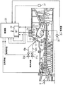
図1はガスタービン設備1を一部断面の側面図で示す。このガスタービン設備は圧縮機部3とタービン部5とバーナ部7とを含む。圧縮機部3とタービン部5とにおいて圧縮機動翼4もしくはタービン動翼6が共通の軸8に配置されており、この軸はタービンロータとも称される。タービンロータ8は中央軸線9の周りを回転可能に支持されている。
FIG. 1 shows a gas turbine facility 1 in a partially sectional side view. This gas turbine equipment includes a compressor section 3, a
バーナ部7が含む複数のバーナ10は燃焼室12に通じ、燃焼室はタービン部5に通じている。燃焼室12は本実施例において環状燃焼室として構成されており、すなわちタービンロータ8の周りで環状に設置されている。
A plurality of
ガスタービン設備1の運転時、圧縮機を介して周囲空気Uが吸い込まれ、高い圧力に圧縮され、いわゆる圧縮機空気としてバーナ部7内に引き渡される。圧縮機に流入する空気質量流量の値は第1静翼リング32を用いて有効圧縮機流入横断面を調整することによって調節することができる。
During operation of the gas turbine facility 1, the ambient air U is sucked in through the compressor, compressed to a high pressure, and delivered to the burner unit 7 as so-called compressor air. The value of the air mass flow rate flowing into the compressor can be adjusted by adjusting the effective compressor inflow cross section using the first
バーナ部7において圧縮機空気がバーナ10に流入し、図2に示すように、燃料管路40a、40bを介してバーナ10に供給される燃料と混合され、燃焼室12において燃焼させられる。その際、供給される燃料質量流量の値は単数または複数の調整弁31a、31bを介して調節することができる。
Compressor air flows into the
燃焼時に発生する燃焼ガスが作動流体Aを形成し、この作動流体はタービン部5に送られ、そこで減圧と冷却を受けながら衝動を動翼6に伝達し、こうしてロータ8を回転させる。回転するロータ8は一方で圧縮機を駆動し、他方で(図示しない)負荷、例えば電気を発生する発電機と連結されている。
Combustion gas generated at the time of combustion forms a working fluid A, and this working fluid is sent to the
燃焼室12内での火炎の不安定性を防止するために、ガスタービン設備1は燃料供給量および/または空気供給量を調節することによって動作系を制御するための制御装置を装備している。この装置は図2にブロック線図の態様で示してある。制御装置は、ガスタービン燃焼室12の内部および外部のさまざまな個所に配置される複数のセンサ21、23、25、27、35、37を含む。制御装置がさらに含む制御器29にセンサ21、23、25、27、35、37は接続されている。さらに操作機構、つまり調整弁31と静翼リング32が設けられており、これらはやはり制御器29と接続され、バーナ10への燃料供給量および空気供給量の質量流量を調整するように構成されている。
In order to prevent instability of the flame in the
このガスタービン設備1では、特に3つの調整可能な燃料質量流量と1つの調整可能な空気質量流量が設けられている。例えば気体燃料が利用される場合、燃料質量流量の1つは拡散モードのときバーナを作動させるためのいわゆる拡散ガス質量流量である。この拡散モードのときガスは燃焼室12内にある火炎に直接噴霧され、事前に空気と混合されるのではない。第2の燃料質量流量は予備混合モード、すなわち供給されたガスが事前に圧縮機空気と混合されかつこの混合気が引き続き燃焼させられるモードのときバーナを作動させるためのいわゆる予備混合ガス質量流量である。最後に本実施例において他の燃料質量流量としてパイロットガス質量流量が設けられており、これはなかんずく、予備混合動作でバーナを作動させるとき火炎を支持するのに役立つ。
In this gas turbine facility 1, in particular, three adjustable fuel mass flows and one adjustable air mass flow are provided. For example, when gaseous fuel is used, one of the fuel mass flows is the so-called diffusion gas mass flow for operating the burner when in diffusion mode. In this diffusion mode, the gas is sprayed directly onto the flame in the
センサ21、23、25、27、35、37でもってさまざまな燃焼室パラメータおよび燃焼パラメータが検出され、検出された測定量を表す信号の態様で制御器29に転送される。
Various combustion chamber parameters and combustion parameters are detected with the
センサ21は燃焼室プレナム11内に配置されて燃焼室12内の交番圧力を検出する圧力センサ、センサ25はガスタービンケーシングに配置されてバーナ10のフランジ13の交番圧力を検出する圧力センサ、センサ23は燃焼室加速度を検出する加速度センサである。加速度センサは燃焼室壁の外面に直接設置されている。
A
検出された3つのパラメータ、つまり燃焼室内の交番圧力とバーナフランジの交番圧力と燃焼室加速度はすべて、燃焼ガス中の振動を反映した振動量である。それゆえに圧力センサ21、25と加速度センサ23は、それらの測定信号を出力するために、制御器29の(図示しない)平均自己相関を算定するためのフーリエ変換ユニット33および/または演算ユニットと接続されている。このフーリエ変換ユニット内でフーリエ変換、特にいわゆる高速フーリエ変換に基づいて測定信号の分析が行われる。それに加えてこれらのセンサは、測定信号の絶対値も制御器29に提供できるようにするために制御器29と直接に、すなわちフーリエ変換ユニット33を迂回して、接続されている。自己相関の判定用に、振動アナログ信号は複数の振動数帯域についてまず正確な振幅でフィルタリングされ、引き続きAD変換され、またはまずAD変換され、引き続き正確な振幅でフィルタリングされる。自己相関は振動数帯域別に短い時間間隔で2乃至8の信号周期に基づいてこれらの振動数帯域の各平均振動数において計算される。引き続き、自己相関は振動数帯域別に、それぞれ各振動数帯域についての先行する時間ステップから10乃至100の相互に相前後する自己相関と一緒に平均化される。各振動数帯域についての自己相関の平均化と同時に、それらの分散が判定される。これらの振動数スペクトルおよび/または平均自己相関および/または自己相関の分散から、個々の振動数または特定の振動数帯域についてトランジェントが形成される。これは例えば線形回帰計算を用いて行うことができる。個々のトランジェントまたはそれで形成された特性量が或る特定値を上まわると、制御介入、例えば出力の低下またはパイロットガス量の変更が行われる。平均自己相関の絶対値およびそれらのトランジェントと場合によっては付加的に自己相関の分散および分散のトランジェントとから形成される特性量が特定値を上まわると、制御介入、例えば出力の低下またはパイロットガス量の変更が行われる。トランジェントを評価することによって、著しく大きな早期警告時間を達成することができる。
The three detected parameters, that is, the alternating pressure in the combustion chamber, the alternating pressure of the burner flange, and the acceleration in the combustion chamber are all vibration amounts reflecting the vibration in the combustion gas. Therefore, the
フーリエ変換の結果に基づいて制御器29はガスタービン設備1の燃焼ガス中に例えば定常振動が現れるバーナ不安定限界への接近を確認することができる。特にバーナフランジ13の交番圧力の測定に基づいて、フーリエ変換ユニット33による分析後、燃焼ガス中の振動の振動数を算定することができる。それゆえにバーナフランジ13の交番圧力はバーナ不安定限界への接近の早期兆候として適し、また火炎安定性が維持されるように空気供給量および/または燃料供給量を制御するための制御器用制御量として適している。
Based on the result of the Fourier transform, the
燃焼室加速度は、バーナ不安定限界への接近に対してバーナフランジ13の交番圧力よりも遅くに反応する。それゆえに燃焼室加速度は、空気および/または燃料供給量の制御が火炎の十分な安定化を生じないときガスタービン燃焼室12を損傷から保護するのに特に適している。燃焼室加速度は例えば、燃焼室を支持する構造体を高温の燃焼排気から保護するために燃焼室12に内張りされたセラミック遮熱要素に損傷が現れることの兆候である。高い燃焼室加速度により遮熱要素に亀裂を生じることがあり、破損を生じることさえあり、そのため遮熱要素はその保護機能をもはや十分には果たさなくなる。それに加えて、破損の結果として破片が遮熱要素から剥がれてタービン部に達することがあり、そのことからきわめて重大なタービン損傷が生じる。それゆえに燃焼室加速度に基づいて、算定された燃焼室加速度が遮熱要素に亀裂または破損の虞のあることを示すとき、例えばガスタービン設備の緊急停止を行うことができる。
The combustion chamber acceleration responds slower than the alternating pressure of the
燃焼室12内の交番圧力、バーナフランジ13の交番圧力および燃焼室加速度の他に、燃焼室12上の圧力勾配とも称される圧力降下も、間近に迫ったバーナ不安定事象を確認するのに利用することができる。燃焼室12の圧力はバーナ不安定化の直前に低下する。これはバーナ10内で火炎減退が迫っていることを示し、従って火炎不安定性を示す。それゆえに圧力勾配を検出するための適切なセンサ装置によってバーナ不安定事象が間近であることの検出が可能である。
In addition to the alternating pressure in the
燃焼室12の圧力降下はいわゆるΔp(差圧)測定によって行われる。本実施
例においてΔp測定は2つの圧力センサ35、37によって実施され、そのうち
一方のセンサ35は燃焼室プレナム11内、他方のセンサ37は燃焼室12内に配置されている。両方の圧力センサ35、37と制御器29とに接続された減算器39は検出された圧力の差Δpを形成し、フーリエ変換ユニット33を迂回し
てこの差を制御器29に伝える。
The pressure drop in the
制御器29はまずなによりも、センサ21、23、25によって検出された測定量の時間的変化に反応し、それらの絶対値に反応することは僅かである。制御器29がセンサ21、23、25から到来する信号の分析後にバーナ不安定限界への接近を確認すると、制御器は操作信号を操作弁31a、31b、…および/または圧縮機静翼リング32に送出し、これらは少なくとも1つの燃料質量流量および/または空気質量流量の変更を誘起する。その場合制御器は特に、パイロット燃料質量流量の変更を介してガスタービン設備の動作系を再び最適にするために、すなわちバーナ不安定限界から遠ざけるために、少なくとも1つの操作信号をパイロット燃料供給管路中の燃料弁に送出する。その際、ガスタービン設備の補正排気温度およびその出力は、主燃料質量流量および/または空気質量流量の調節を介して、有害物質排出量がその最適値に保たれもしくは再びこの値に調整されるように、調整することができる。
The
さらに、例えば変動する影響量、例えば変動する周囲温度のゆえに有害物質排出量が変化するときには、パイロットガス質量流量および/またはガスタービン出力および/または補正排気温度の調節を介して例えば有害物質排出量を所定範囲内に保つために、ガスタービン設備の動作系を新たに最適化することなく、操作弁31a、31b、…もしくは静翼リング32を燃料質量流量および/または空気質量流量のみに作用させることができる。
Further, for example, when the toxic substance emissions change due to varying influence quantities, for example due to varying ambient temperatures, for example toxic substance emissions via adjustment of pilot gas mass flow and / or gas turbine output and / or corrected exhaust temperature. In order to keep the operation range within a predetermined range, the
有害物質値の高まりに対しては例えばパイロットガス質量流量に対する作用によって反応することができる。排ガス中の窒素酸化物値が高くまたは高まり、排ガス中の一酸化炭素値が高いとき、パイロットガス質量流量は減らすことができる。排気中の有害物質値の検出は本実施例において排出量測定装置27によって行われ、この排出量測定装置は燃焼室設備の排ガス通路中に配置され、フーリエ変換ユニット33を迂回して制御器29と接続されている。
The increase in the harmful substance value can be reacted by, for example, the effect on the pilot gas mass flow rate. When the nitrogen oxide value in the exhaust gas is high or increased and the carbon monoxide value in the exhaust gas is high, the pilot gas mass flow rate can be reduced. In the present embodiment, the detection of the harmful substance value in the exhaust gas is performed by the
本実施例において制御器29は、極力等級区分された反応を可能とするためにファジィ論理に基づいて作動する。しかし制御器は固定制御規則で作動することもできる。この固定制御規則は、例えば出力されるべき操作信号と到来する測定信号との間の機能的関連として存在し、または到来する測定信号と出発する操作信号とを結びつける表の態様で存在する。最後に、ニューラルネットワークに基づく制御器を投入することも可能であり、これにより制御器は先行する制御事象を学習する状態にされる。
In this embodiment, the
1 ガスタービン設備
3 圧縮機部
4 圧縮機動翼
5 タービン部
6 タービン動翼
7 バーナ部
8 軸
9 軸線
10 バーナ
11 燃焼室プレナム
12 燃焼室
13 フランジ
21、23、25、27 センサ
29 制御器
31 調整弁
32 静翼リング
33 フーリエ変換ユニット
35、37 圧力センサ
39 減算器
40 燃料管路
A 作動流体
U 周囲空気
DESCRIPTION OF SYMBOLS 1 Gas turbine equipment 3 Compressor part 4
Claims (23)
‐少なくとも1つの制御量を検出するステップと、
‐検出された制御量を所定の基準量と比較するステップと、
‐制御量と基準量との比較に基づいて少なくとも1つの操作量を算定するステップと、
‐算定された操作量を、ガスタービン設備(1)の燃焼室(12)への空気供給量および/または燃料供給量を調節する少なくとも1つの操作機構(31、32)に対して出力するステップとを含み、安定性限界への火炎の接近を表示する制御量が前記少なくとも1つの制御量として使用される制御方法において、
前記制御量としてバーナフランジの少なくとも1つの交番圧力の時間的変化が使用されることを特徴とする制御方法。A control method for controlling the operating system of the gas turbine equipment (1),
-Detecting at least one controlled variable;
-Comparing the detected control amount with a predetermined reference amount;
-Calculating at least one manipulated variable based on a comparison between the control quantity and a reference quantity;
Outputting the calculated operation amount to at least one operation mechanism (31, 32) for adjusting the air supply amount and / or the fuel supply amount to the combustion chamber (12) of the gas turbine equipment (1); And a control amount indicating the approach of the flame to the stability limit is used as the at least one control amount ,
The control method characterized in that a temporal change of at least one alternating pressure of the burner flange is used as the control amount .
‐測定量を検出しかつこの測定量を表す測定信号を出力するための少なくとも1つのセンサ(21、23、25、27、35、37)と、
‐ガスタービン設備の燃焼室(12)への空気供給量および/または燃料供給量を操作量に基づいて調節するための少なくとも1つの操作機構(31、32)と、
‐制御器(29)とを有し、この制御器は測定量を受信するための前記少なくとも1つのセンサ(21、23、25、27、35、37)と、操作量を出力するための前記少なくとも1つの操作機構(31、32)とに接続されており、この制御器が、受信した測定量と基準量からの測定量の偏差とに基づいて操作量を算定するように構成されている制御装置において、
‐前記センサとして、バーナフランジ(13)の少なくとも1つの交番圧力の時間的変化を検出するセンサ(25)を備えていることを特徴とする制御装置。A control device for controlling the operating system of the gas turbine equipment (1),
At least one sensor (21, 23, 25, 27, 35, 37) for detecting a measured quantity and outputting a measurement signal representative of this measured quantity;
-At least one operating mechanism (31, 32) for adjusting the amount of air and / or fuel supplied to the combustion chamber (12) of the gas turbine facility based on the amount of operation;
A controller (29), said controller for receiving the measured quantity (21, 23, 25, 27, 35, 37) and for outputting the manipulated variable The controller is connected to at least one operation mechanism (31, 32), and the controller is configured to calculate the operation amount based on the received measurement amount and the deviation of the measurement amount from the reference amount. In the control device ,
- as the sensor, characterized in that it comprises a sensor (25) for detecting a temporal change of at least one alternating pressure of the burner flange (13) control device.
Applications Claiming Priority (3)
| Application Number | Priority Date | Filing Date | Title |
|---|---|---|---|
| EP05010543A EP1724528A1 (en) | 2005-05-13 | 2005-05-13 | Method and apparatus for regulating the functioning of a gas turbine combustor |
| EP05010543.6 | 2005-05-13 | ||
| PCT/EP2006/062183 WO2006120206A1 (en) | 2005-05-13 | 2006-05-10 | Process and device for regulating the course of a gas turbine combustion chamber |
Publications (2)
| Publication Number | Publication Date |
|---|---|
| JP2008540911A JP2008540911A (en) | 2008-11-20 |
| JP4806012B2 true JP4806012B2 (en) | 2011-11-02 |
Family
ID=35559378
Family Applications (1)
| Application Number | Title | Priority Date | Filing Date |
|---|---|---|---|
| JP2008510571A Active JP4806012B2 (en) | 2005-05-13 | 2006-05-10 | Method and apparatus for controlling the operating system of a gas turbine combustion chamber |
Country Status (7)
| Country | Link |
|---|---|
| US (1) | US9086219B2 (en) |
| EP (2) | EP1724528A1 (en) |
| JP (1) | JP4806012B2 (en) |
| CN (1) | CN101166935B (en) |
| CA (1) | CA2608042C (en) |
| RU (1) | RU2413083C2 (en) |
| WO (1) | WO2006120206A1 (en) |
Families Citing this family (30)
| Publication number | Priority date | Publication date | Assignee | Title |
|---|---|---|---|---|
| DE102007001024B4 (en) | 2007-01-02 | 2008-10-02 | Siemens Ag | Method for computer-aided control and / or control of a technical system, in particular of a gas turbine |
| EP1990521A1 (en) * | 2007-05-09 | 2008-11-12 | Siemens Aktiengesellschaft | Pressure dynamics reduction within a gas turbine engine |
| EP2071157B1 (en) | 2007-12-10 | 2014-01-15 | Alstom Technology Ltd | Method for controlling a gas turbine in a power plant |
| US8434291B2 (en) * | 2009-01-08 | 2013-05-07 | General Electric Company | Systems and methods for detecting a flame in a fuel nozzle of a gas turbine |
| US9115648B2 (en) | 2009-04-10 | 2015-08-25 | General Electric Company | Corrected megawatt backup curve methodology |
| US8437941B2 (en) | 2009-05-08 | 2013-05-07 | Gas Turbine Efficiency Sweden Ab | Automated tuning of gas turbine combustion systems |
| US9671797B2 (en) | 2009-05-08 | 2017-06-06 | Gas Turbine Efficiency Sweden Ab | Optimization of gas turbine combustion systems low load performance on simple cycle and heat recovery steam generator applications |
| US9354618B2 (en) | 2009-05-08 | 2016-05-31 | Gas Turbine Efficiency Sweden Ab | Automated tuning of multiple fuel gas turbine combustion systems |
| US9267443B2 (en) | 2009-05-08 | 2016-02-23 | Gas Turbine Efficiency Sweden Ab | Automated tuning of gas turbine combustion systems |
| IT1396515B1 (en) * | 2009-11-27 | 2012-12-14 | Nuovo Pignone Spa | THRESHOLD BASED ON DISCHARGE TEMPERATURE FOR CONTROL METHOD AND TURBINE |
| EP2568145B1 (en) * | 2011-09-08 | 2018-03-21 | Ansaldo Energia IP UK Limited | Gas turbine controller and a method for controlling a gas turbine |
| US20130167549A1 (en) * | 2011-12-29 | 2013-07-04 | Chad M. Holcomb | Compressor guide vane and pilot control for gas turbine engine |
| US9002615B2 (en) * | 2012-01-18 | 2015-04-07 | General Electric Company | Methods and systems for managing power of an engine |
| US8903753B2 (en) * | 2012-02-06 | 2014-12-02 | General Electric Company | Steam turbine performance testing |
| US20140170574A1 (en) * | 2012-12-17 | 2014-06-19 | Exxonmobil Research And Engineering Company | Flame instability detector |
| US9376963B2 (en) * | 2013-01-16 | 2016-06-28 | Alstom Technology Ltd. | Detecting flashback by monitoring engine-dynamic spikes |
| EP2789915A1 (en) * | 2013-04-10 | 2014-10-15 | Alstom Technology Ltd | Method for operating a combustion chamber and combustion chamber |
| US20150075170A1 (en) * | 2013-09-17 | 2015-03-19 | General Electric Company | Method and system for augmenting the detection reliability of secondary flame detectors in a gas turbine |
| EP2899385A1 (en) * | 2014-01-22 | 2015-07-29 | Siemens Aktiengesellschaft | Method for regulating a gas turbine |
| EP2942565A1 (en) * | 2014-05-05 | 2015-11-11 | Siemens Aktiengesellschaft | Method for operating a burner assembly |
| US9909508B2 (en) * | 2014-06-26 | 2018-03-06 | General Electric Company | Automatic combustion system characterization |
| CN104750066B (en) * | 2015-02-10 | 2019-10-01 | 北京华清燃气轮机与煤气化联合循环工程技术有限公司 | Gas turbine combustion process control and optimization system |
| CN107560864B (en) * | 2016-06-30 | 2020-10-16 | 西门子公司 | Method and apparatus for scale monitoring and prediction in combustors |
| US10830443B2 (en) * | 2016-11-30 | 2020-11-10 | General Electric Company | Model-less combustion dynamics autotune |
| EP3456946A1 (en) * | 2017-09-18 | 2019-03-20 | Siemens Aktiengesellschaft | Controller & method |
| CN109162814B (en) * | 2018-09-03 | 2019-11-26 | 华电电力科学研究院有限公司 | A kind of DLN-2.6 combustion system firing optimization method |
| JP7176932B2 (en) * | 2018-11-08 | 2022-11-22 | 三菱重工業株式会社 | Gas turbine control device, gas turbine equipment, gas turbine control method, and gas turbine control program |
| CN109579054A (en) * | 2018-11-26 | 2019-04-05 | 西安热工研究院有限公司 | A kind of gas turbine combustion method of adjustment based on flame temperature control |
| CN112596415B (en) * | 2020-12-18 | 2023-01-03 | 上海明华电力科技有限公司 | Combustion engine combustion optimization closed-loop control method with feedforward |
| CN114265313B (en) * | 2021-12-23 | 2024-02-13 | 河钢数字信达(邯郸)科技有限公司 | Air valve optimization strategy method based on exhaust gas temperature rising curve |
Citations (6)
| Publication number | Priority date | Publication date | Assignee | Title |
|---|---|---|---|---|
| JPH0598996A (en) * | 1991-10-05 | 1993-04-20 | Kawasaki Heavy Ind Ltd | Gas turbine start control system |
| JPH0842361A (en) * | 1994-05-02 | 1996-02-13 | General Electric Co <Ge> | Operating method of gas turbine and gas-turbine control system |
| JPH1122490A (en) * | 1997-07-07 | 1999-01-26 | Mitsubishi Heavy Ind Ltd | Automatic pilot ratio adjusting device |
| JP2000130750A (en) * | 1998-10-28 | 2000-05-12 | Hitachi Ltd | Combustion monitoring device |
| JP2003293793A (en) * | 2002-04-05 | 2003-10-15 | Mitsubishi Heavy Ind Ltd | Combustion vibration sign detector, gas turbine system, and combustion vibration sign detection method |
| JP2004162698A (en) * | 2002-11-13 | 2004-06-10 | General Electric Co <Ge> | Adaptation control system for model base for controlling gas turbine |
Family Cites Families (18)
| Publication number | Priority date | Publication date | Assignee | Title |
|---|---|---|---|---|
| US4041694A (en) * | 1975-08-25 | 1977-08-16 | United Technologies Corporation | Combustion temperature control |
| GB9018013D0 (en) * | 1990-08-16 | 1990-10-03 | Rolls Royce Plc | Gas turbine engine combustor |
| US5117624A (en) * | 1990-09-17 | 1992-06-02 | General Electric Company | Fuel injector nozzle support |
| US5487266A (en) * | 1992-05-05 | 1996-01-30 | General Electric Company | Combustion control for producing low NOx emissions through use of flame spectroscopy |
| AU7771494A (en) * | 1993-12-03 | 1995-06-08 | Westinghouse Electric Corporation | System for controlling combustion in a gas combustion-type turbine |
| JPH07189746A (en) * | 1993-12-28 | 1995-07-28 | Hitachi Ltd | Gas turbine combustor control method |
| DE69621585T2 (en) * | 1995-10-19 | 2002-12-19 | Mitsubishi Motors Corp | DEVICE FOR REPLACING BURNERS |
| US6560967B1 (en) * | 1998-05-29 | 2003-05-13 | Jeffrey Mark Cohen | Method and apparatus for use with a gas fueled combustor |
| JP3783442B2 (en) * | 1999-01-08 | 2006-06-07 | 株式会社日立製作所 | Control method of gas turbine |
| US6389815B1 (en) * | 2000-09-08 | 2002-05-21 | General Electric Company | Fuel nozzle assembly for reduced exhaust emissions |
| US6715916B2 (en) * | 2001-02-08 | 2004-04-06 | General Electric Company | System and method for determining gas turbine firing and combustion reference temperatures having correction for water content in fuel |
| JP4056232B2 (en) * | 2001-08-23 | 2008-03-05 | 三菱重工業株式会社 | Gas turbine control device, gas turbine system, and gas turbine remote monitoring system |
| JP2003113721A (en) * | 2001-10-03 | 2003-04-18 | Mitsubishi Heavy Ind Ltd | Fuel ratio control method and device for gas turbine combustor |
| US6742340B2 (en) * | 2002-01-29 | 2004-06-01 | Affordable Turbine Power Company, Inc. | Fuel injection control system for a turbine engine |
| JP3978086B2 (en) * | 2002-05-31 | 2007-09-19 | 三菱重工業株式会社 | Aircraft gas turbine system, gas turbine system, and operation method thereof |
| US6718770B2 (en) * | 2002-06-04 | 2004-04-13 | General Electric Company | Fuel injector laminated fuel strip |
| JP3975232B2 (en) * | 2002-10-22 | 2007-09-12 | 川崎重工業株式会社 | Control method and control system for gas turbine engine |
| US8733078B2 (en) * | 2010-11-10 | 2014-05-27 | United Technologies Corporation | Igniter with integral pressure sensing line |
-
2005
- 2005-05-13 EP EP05010543A patent/EP1724528A1/en not_active Withdrawn
-
2006
- 2006-05-10 RU RU2007146461/06A patent/RU2413083C2/en active
- 2006-05-10 JP JP2008510571A patent/JP4806012B2/en active Active
- 2006-05-10 WO PCT/EP2006/062183 patent/WO2006120206A1/en active Application Filing
- 2006-05-10 CA CA2608042A patent/CA2608042C/en active Active
- 2006-05-10 US US11/920,396 patent/US9086219B2/en active Active
- 2006-05-10 EP EP06755118.4A patent/EP1880141B1/en active Active
- 2006-05-10 CN CN200680014475XA patent/CN101166935B/en active Active
Patent Citations (6)
| Publication number | Priority date | Publication date | Assignee | Title |
|---|---|---|---|---|
| JPH0598996A (en) * | 1991-10-05 | 1993-04-20 | Kawasaki Heavy Ind Ltd | Gas turbine start control system |
| JPH0842361A (en) * | 1994-05-02 | 1996-02-13 | General Electric Co <Ge> | Operating method of gas turbine and gas-turbine control system |
| JPH1122490A (en) * | 1997-07-07 | 1999-01-26 | Mitsubishi Heavy Ind Ltd | Automatic pilot ratio adjusting device |
| JP2000130750A (en) * | 1998-10-28 | 2000-05-12 | Hitachi Ltd | Combustion monitoring device |
| JP2003293793A (en) * | 2002-04-05 | 2003-10-15 | Mitsubishi Heavy Ind Ltd | Combustion vibration sign detector, gas turbine system, and combustion vibration sign detection method |
| JP2004162698A (en) * | 2002-11-13 | 2004-06-10 | General Electric Co <Ge> | Adaptation control system for model base for controlling gas turbine |
Also Published As
| Publication number | Publication date |
|---|---|
| CA2608042A1 (en) | 2006-11-16 |
| RU2007146461A (en) | 2009-06-20 |
| CA2608042C (en) | 2012-11-13 |
| EP1880141B1 (en) | 2014-10-01 |
| JP2008540911A (en) | 2008-11-20 |
| CN101166935A (en) | 2008-04-23 |
| CN101166935B (en) | 2010-05-19 |
| WO2006120206A1 (en) | 2006-11-16 |
| EP1880141A1 (en) | 2008-01-23 |
| RU2413083C2 (en) | 2011-02-27 |
| EP1724528A1 (en) | 2006-11-22 |
| US20090301097A1 (en) | 2009-12-10 |
| US9086219B2 (en) | 2015-07-21 |
Similar Documents
| Publication | Publication Date | Title |
|---|---|---|
| JP4806012B2 (en) | Method and apparatus for controlling the operating system of a gas turbine combustion chamber | |
| JP5150613B2 (en) | Method and system for controlling a combustor of a turbine engine | |
| CA2344210C (en) | Dynamic control system and method for catalytic combustion process and gas turbine engine utilizing same | |
| US5533329A (en) | Control apparatus for and control method of gas turbine | |
| US6775986B2 (en) | Gas turbine and method for suppressing azimuthal fluctuation modes in a gas turbine | |
| JP4761768B2 (en) | Method and apparatus for reducing combustor dynamic pressure during operation of a gas turbine engine | |
| US7617686B2 (en) | Method for determination of the temperature, mass-averaged over a flow cross-section, of a gas flow in a gas turbine | |
| EP2486328B1 (en) | Combustion apparatus | |
| EP2107305A1 (en) | Gas turbine system and method | |
| EP2813685B1 (en) | Disc shaft center adjusting mechanism in gas turbine | |
| WO2010035539A1 (en) | Gas turbine control method and controller | |
| JP6010283B2 (en) | System and method for operating a gas turbine | |
| US20110167782A1 (en) | Systems and apparatus for a fuel control assembly for use in a gas turbine engine | |
| JP6144908B2 (en) | System and method for operating a gas turbine | |
| JP5738214B2 (en) | Disk axis adjustment mechanism in gas turbine | |
| JP4990902B2 (en) | Method for protecting a gas turbine device from overheating of the part guiding the hot gas and detecting the disappearance of the flame in the combustion chamber | |
| EP3784890B1 (en) | Combustion system control | |
| JPS61210233A (en) | Gas turbine temperature control device | |
| JP5281467B2 (en) | Control method of gas turbine combustor |
Legal Events
| Date | Code | Title | Description |
|---|---|---|---|
| A131 | Notification of reasons for refusal |
Free format text: JAPANESE INTERMEDIATE CODE: A131 Effective date: 20100601 |
|
| A601 | Written request for extension of time |
Free format text: JAPANESE INTERMEDIATE CODE: A601 Effective date: 20100831 |
|
| RD03 | Notification of appointment of power of attorney |
Free format text: JAPANESE INTERMEDIATE CODE: A7423 Effective date: 20100831 |
|
| A602 | Written permission of extension of time |
Free format text: JAPANESE INTERMEDIATE CODE: A602 Effective date: 20100907 |
|
| A521 | Request for written amendment filed |
Free format text: JAPANESE INTERMEDIATE CODE: A523 Effective date: 20100929 |
|
| A131 | Notification of reasons for refusal |
Free format text: JAPANESE INTERMEDIATE CODE: A131 Effective date: 20101207 |
|
| TRDD | Decision of grant or rejection written | ||
| A01 | Written decision to grant a patent or to grant a registration (utility model) |
Free format text: JAPANESE INTERMEDIATE CODE: A01 Effective date: 20110719 |
|
| A01 | Written decision to grant a patent or to grant a registration (utility model) |
Free format text: JAPANESE INTERMEDIATE CODE: A01 |
|
| A61 | First payment of annual fees (during grant procedure) |
Free format text: JAPANESE INTERMEDIATE CODE: A61 Effective date: 20110811 |
|
| R150 | Certificate of patent or registration of utility model |
Ref document number: 4806012 Country of ref document: JP Free format text: JAPANESE INTERMEDIATE CODE: R150 Free format text: JAPANESE INTERMEDIATE CODE: R150 |
|
| FPAY | Renewal fee payment (event date is renewal date of database) |
Free format text: PAYMENT UNTIL: 20140819 Year of fee payment: 3 |
|
| R250 | Receipt of annual fees |
Free format text: JAPANESE INTERMEDIATE CODE: R250 |
|
| R250 | Receipt of annual fees |
Free format text: JAPANESE INTERMEDIATE CODE: R250 |
|
| R250 | Receipt of annual fees |
Free format text: JAPANESE INTERMEDIATE CODE: R250 |
|
| R250 | Receipt of annual fees |
Free format text: JAPANESE INTERMEDIATE CODE: R250 |
|
| R250 | Receipt of annual fees |
Free format text: JAPANESE INTERMEDIATE CODE: R250 |
|
| R250 | Receipt of annual fees |
Free format text: JAPANESE INTERMEDIATE CODE: R250 |
|
| R250 | Receipt of annual fees |
Free format text: JAPANESE INTERMEDIATE CODE: R250 |
|
| R250 | Receipt of annual fees |
Free format text: JAPANESE INTERMEDIATE CODE: R250 |
|
| R250 | Receipt of annual fees |
Free format text: JAPANESE INTERMEDIATE CODE: R250 |
|
| S111 | Request for change of ownership or part of ownership |
Free format text: JAPANESE INTERMEDIATE CODE: R313113 |
|
| S531 | Written request for registration of change of domicile |
Free format text: JAPANESE INTERMEDIATE CODE: R313531 |
|
| R350 | Written notification of registration of transfer |
Free format text: JAPANESE INTERMEDIATE CODE: R350 |
|
| R250 | Receipt of annual fees |
Free format text: JAPANESE INTERMEDIATE CODE: R250 |