JP4056232B2 - Gas turbine control device, gas turbine system, and gas turbine remote monitoring system - Google Patents
Gas turbine control device, gas turbine system, and gas turbine remote monitoring system Download PDFInfo
- Publication number
- JP4056232B2 JP4056232B2 JP2001253299A JP2001253299A JP4056232B2 JP 4056232 B2 JP4056232 B2 JP 4056232B2 JP 2001253299 A JP2001253299 A JP 2001253299A JP 2001253299 A JP2001253299 A JP 2001253299A JP 4056232 B2 JP4056232 B2 JP 4056232B2
- Authority
- JP
- Japan
- Prior art keywords
- gas turbine
- flow rate
- unit
- frequency band
- frequency
- Prior art date
- Legal status (The legal status is an assumption and is not a legal conclusion. Google has not performed a legal analysis and makes no representation as to the accuracy of the status listed.)
- Expired - Lifetime
Links
Images


Classifications
-
- F—MECHANICAL ENGINEERING; LIGHTING; HEATING; WEAPONS; BLASTING
- F02—COMBUSTION ENGINES; HOT-GAS OR COMBUSTION-PRODUCT ENGINE PLANTS
- F02C—GAS-TURBINE PLANTS; AIR INTAKES FOR JET-PROPULSION PLANTS; CONTROLLING FUEL SUPPLY IN AIR-BREATHING JET-PROPULSION PLANTS
- F02C7/00—Features, components parts, details or accessories, not provided for in, or of interest apart form groups F02C1/00 - F02C6/00; Air intakes for jet-propulsion plants
- F02C7/22—Fuel supply systems
- F02C7/228—Dividing fuel between various burners
-
- F—MECHANICAL ENGINEERING; LIGHTING; HEATING; WEAPONS; BLASTING
- F01—MACHINES OR ENGINES IN GENERAL; ENGINE PLANTS IN GENERAL; STEAM ENGINES
- F01D—NON-POSITIVE DISPLACEMENT MACHINES OR ENGINES, e.g. STEAM TURBINES
- F01D17/00—Regulating or controlling by varying flow
- F01D17/10—Final actuators
- F01D17/12—Final actuators arranged in stator parts
- F01D17/14—Final actuators arranged in stator parts varying effective cross-sectional area of nozzles or guide conduits
- F01D17/16—Final actuators arranged in stator parts varying effective cross-sectional area of nozzles or guide conduits by means of nozzle vanes
- F01D17/162—Final actuators arranged in stator parts varying effective cross-sectional area of nozzles or guide conduits by means of nozzle vanes for axial flow, i.e. the vanes turning around axes which are essentially perpendicular to the rotor centre line
-
- F—MECHANICAL ENGINEERING; LIGHTING; HEATING; WEAPONS; BLASTING
- F02—COMBUSTION ENGINES; HOT-GAS OR COMBUSTION-PRODUCT ENGINE PLANTS
- F02C—GAS-TURBINE PLANTS; AIR INTAKES FOR JET-PROPULSION PLANTS; CONTROLLING FUEL SUPPLY IN AIR-BREATHING JET-PROPULSION PLANTS
- F02C9/00—Controlling gas-turbine plants; Controlling fuel supply in air- breathing jet-propulsion plants
- F02C9/16—Control of working fluid flow
- F02C9/18—Control of working fluid flow by bleeding, bypassing or acting on variable working fluid interconnections between turbines or compressors or their stages
-
- F—MECHANICAL ENGINEERING; LIGHTING; HEATING; WEAPONS; BLASTING
- F02—COMBUSTION ENGINES; HOT-GAS OR COMBUSTION-PRODUCT ENGINE PLANTS
- F02C—GAS-TURBINE PLANTS; AIR INTAKES FOR JET-PROPULSION PLANTS; CONTROLLING FUEL SUPPLY IN AIR-BREATHING JET-PROPULSION PLANTS
- F02C9/00—Controlling gas-turbine plants; Controlling fuel supply in air- breathing jet-propulsion plants
- F02C9/16—Control of working fluid flow
- F02C9/20—Control of working fluid flow by throttling; by adjusting vanes
- F02C9/22—Control of working fluid flow by throttling; by adjusting vanes by adjusting turbine vanes
-
- F—MECHANICAL ENGINEERING; LIGHTING; HEATING; WEAPONS; BLASTING
- F02—COMBUSTION ENGINES; HOT-GAS OR COMBUSTION-PRODUCT ENGINE PLANTS
- F02C—GAS-TURBINE PLANTS; AIR INTAKES FOR JET-PROPULSION PLANTS; CONTROLLING FUEL SUPPLY IN AIR-BREATHING JET-PROPULSION PLANTS
- F02C9/00—Controlling gas-turbine plants; Controlling fuel supply in air- breathing jet-propulsion plants
- F02C9/26—Control of fuel supply
- F02C9/263—Control of fuel supply by means of fuel metering valves
-
- F—MECHANICAL ENGINEERING; LIGHTING; HEATING; WEAPONS; BLASTING
- F02—COMBUSTION ENGINES; HOT-GAS OR COMBUSTION-PRODUCT ENGINE PLANTS
- F02C—GAS-TURBINE PLANTS; AIR INTAKES FOR JET-PROPULSION PLANTS; CONTROLLING FUEL SUPPLY IN AIR-BREATHING JET-PROPULSION PLANTS
- F02C9/00—Controlling gas-turbine plants; Controlling fuel supply in air- breathing jet-propulsion plants
- F02C9/26—Control of fuel supply
- F02C9/28—Regulating systems responsive to plant or ambient parameters, e.g. temperature, pressure, rotor speed
-
- F—MECHANICAL ENGINEERING; LIGHTING; HEATING; WEAPONS; BLASTING
- F02—COMBUSTION ENGINES; HOT-GAS OR COMBUSTION-PRODUCT ENGINE PLANTS
- F02C—GAS-TURBINE PLANTS; AIR INTAKES FOR JET-PROPULSION PLANTS; CONTROLLING FUEL SUPPLY IN AIR-BREATHING JET-PROPULSION PLANTS
- F02C9/00—Controlling gas-turbine plants; Controlling fuel supply in air- breathing jet-propulsion plants
- F02C9/48—Control of fuel supply conjointly with another control of the plant
- F02C9/50—Control of fuel supply conjointly with another control of the plant with control of working fluid flow
- F02C9/52—Control of fuel supply conjointly with another control of the plant with control of working fluid flow by bleeding or by-passing the working fluid
-
- F—MECHANICAL ENGINEERING; LIGHTING; HEATING; WEAPONS; BLASTING
- F23—COMBUSTION APPARATUS; COMBUSTION PROCESSES
- F23R—GENERATING COMBUSTION PRODUCTS OF HIGH PRESSURE OR HIGH VELOCITY, e.g. GAS-TURBINE COMBUSTION CHAMBERS
- F23R3/00—Continuous combustion chambers using liquid or gaseous fuel
- F23R3/02—Continuous combustion chambers using liquid or gaseous fuel characterised by the air-flow or gas-flow configuration
- F23R3/26—Controlling the air flow
-
- F—MECHANICAL ENGINEERING; LIGHTING; HEATING; WEAPONS; BLASTING
- F05—INDEXING SCHEMES RELATING TO ENGINES OR PUMPS IN VARIOUS SUBCLASSES OF CLASSES F01-F04
- F05D—INDEXING SCHEME FOR ASPECTS RELATING TO NON-POSITIVE-DISPLACEMENT MACHINES OR ENGINES, GAS-TURBINES OR JET-PROPULSION PLANTS
- F05D2260/00—Function
- F05D2260/96—Preventing, counteracting or reducing vibration or noise
-
- F—MECHANICAL ENGINEERING; LIGHTING; HEATING; WEAPONS; BLASTING
- F05—INDEXING SCHEMES RELATING TO ENGINES OR PUMPS IN VARIOUS SUBCLASSES OF CLASSES F01-F04
- F05D—INDEXING SCHEME FOR ASPECTS RELATING TO NON-POSITIVE-DISPLACEMENT MACHINES OR ENGINES, GAS-TURBINES OR JET-PROPULSION PLANTS
- F05D2270/00—Control
- F05D2270/01—Purpose of the control system
- F05D2270/08—Purpose of the control system to produce clean exhaust gases
- F05D2270/083—Purpose of the control system to produce clean exhaust gases by monitoring combustion conditions
-
- F—MECHANICAL ENGINEERING; LIGHTING; HEATING; WEAPONS; BLASTING
- F05—INDEXING SCHEMES RELATING TO ENGINES OR PUMPS IN VARIOUS SUBCLASSES OF CLASSES F01-F04
- F05D—INDEXING SCHEME FOR ASPECTS RELATING TO NON-POSITIVE-DISPLACEMENT MACHINES OR ENGINES, GAS-TURBINES OR JET-PROPULSION PLANTS
- F05D2270/00—Control
- F05D2270/01—Purpose of the control system
- F05D2270/14—Purpose of the control system to control thermoacoustic behaviour in the combustion chambers
-
- F—MECHANICAL ENGINEERING; LIGHTING; HEATING; WEAPONS; BLASTING
- F23—COMBUSTION APPARATUS; COMBUSTION PROCESSES
- F23N—REGULATING OR CONTROLLING COMBUSTION
- F23N2241/00—Applications
- F23N2241/20—Gas turbines
-
- F—MECHANICAL ENGINEERING; LIGHTING; HEATING; WEAPONS; BLASTING
- F23—COMBUSTION APPARATUS; COMBUSTION PROCESSES
- F23N—REGULATING OR CONTROLLING COMBUSTION
- F23N5/00—Systems for controlling combustion
- F23N5/16—Systems for controlling combustion using noise-sensitive detectors
-
- F—MECHANICAL ENGINEERING; LIGHTING; HEATING; WEAPONS; BLASTING
- F23—COMBUSTION APPARATUS; COMBUSTION PROCESSES
- F23R—GENERATING COMBUSTION PRODUCTS OF HIGH PRESSURE OR HIGH VELOCITY, e.g. GAS-TURBINE COMBUSTION CHAMBERS
- F23R2900/00—Special features of, or arrangements for continuous combustion chambers; Combustion processes therefor
- F23R2900/00013—Reducing thermo-acoustic vibrations by active means
-
- F—MECHANICAL ENGINEERING; LIGHTING; HEATING; WEAPONS; BLASTING
- F23—COMBUSTION APPARATUS; COMBUSTION PROCESSES
- F23R—GENERATING COMBUSTION PRODUCTS OF HIGH PRESSURE OR HIGH VELOCITY, e.g. GAS-TURBINE COMBUSTION CHAMBERS
- F23R2900/00—Special features of, or arrangements for continuous combustion chambers; Combustion processes therefor
- F23R2900/00014—Reducing thermo-acoustic vibrations by passive means, e.g. by Helmholtz resonators
Description
【0001】
【発明の属する技術分野】
本発明は、ガスタービンの制御を行なう装置及びそれを有するシステムに関し、特に、燃焼振動を抑制する制御を行なう制御装置及びそれを有するシステムに関する。
【0002】
【従来の技術】
従来のガスタービンでは、発電機出力、大気温度・湿度などに基づいて、燃焼器へ送る空気流量、燃料流量を予め決定し、その値を用いて運転を行なっている。しかし、圧縮機の性能劣化やフィルターの目詰まりなどの経年変化により、実際の流量は計画時や試運転調整時とずれる可能性がある。その場合、燃焼安定性が低下したり、燃焼振動が発生する恐れがある。燃焼振動が発生すると、ガスタービンの運転に大きな支障をきたす。すなわち、燃焼振動を出来る限り抑制し、回避することは、プラントの設備保護上及び稼働率向上の観点から強く求められる。従って、燃焼安定性を保ち、燃焼振動を避けるために、年に数回の制御系の調整を熟練調整員により実施して、燃焼安定性を確認・維持しており、それが保守コストアップ、稼動率低下の原因となっている。
【0003】
特開平9−269107号公報に、燃焼器の燃焼振動抑制装置およびその抑制方法が開示されている。
この燃焼器の燃焼振動抑制装置は、燃焼振動抑制部を備える。燃焼振動抑制部は、燃焼器内の圧力センサーによって検出された、燃焼ガスの圧力変動を周波数分析する周波数分析装置と、この周波数分析装置によって検出された圧力変動の周波数帯域に基づき振動安定性を処理する中央演算処理装置と、この中央演算処理装置の出力信号を増幅する電圧増幅器と、増幅された出力信号を弁開閉信号として燃料弁に与えて制御するコントローラ部とをそれぞれ備える。
【0004】
この抑制方法は、低周波数の燃焼振動に着目している。燃焼振動が起きた時の燃空比から、燃焼振動の周波数を予測する。そして、低周波数の燃焼振動の場合、燃空比を変化させて、低周波の燃焼振動の発生を抑制することができる。低周波の燃焼振動は、機器に影響を与えやすいので、それを抑制することで、機器の損傷を抑制する。
【0005】
【発明が解決しようとする課題】
従って、本発明の目的は、ガスタービンで発生する燃焼振動を抑制し、燃焼安定性を向上することができるガスタービン制御装置及びガスタービンシステムを提供することである。
【0006】
また、本発明の別の目的は、ガスタービンで行なう燃焼を、低公害で実施することが可能なガスタービン制御装置及びガスタービンシステムを提供することである。
【0007】
また、本発明の更に別の目的は、ガスタービンで発生する燃焼振動の周波数を解析し、その解析結果に基づいて、燃焼振動の抑制を適切に実行可能なガスタービン制御装置及びガスタービンシステムを提供することである。
【0008】
本発明の更に他の目的は、ガスタービンの経年変化に対しても、燃焼安定性を維持することが可能なガスタービン制御装置及びガスタービンシステムを提供することである。
【0009】
本発明の更に他の目的は、ガスタービンの運転の信頼性を高めるとともに、寿命を延長し、メンテナンス等にかかるコストを低減することが可能なガスタービン制御装置及びガスタービンシステムを提供することである。
【0010】
更に、本発明の他の目的は、ガスタービンの運転状況を遠隔地において監視し、異常発生時にも遠隔地で対応が可能なガスタービン遠隔監視システムを提供することである。
【0011】
更に、本発明の他の目的は、複数のガスタービンの運転状況を遠隔地において集中監視し、運転管理の効率化を図ることが可能なガスタービン遠隔監視システムを提供することである。
【0012】
【課題を解決するための手段】
以下に、[発明の実施の形態]で使用される番号・符号を用いて、課題を解決するための手段を説明する。これらの番号・符号は、[特許請求の範囲]の記載と[発明の実施の形態]との対応関係を明らかにするために付加されたものである。ただし、それらの番号・符号を、[特許請求の範囲]に記載されている発明の技術的範囲の解釈に用いてはならない。
【0013】
従って、上記課題を解決するために、本発明のガスタービン制御装置は、ガスタービン(2)の燃焼器(111)内での圧力の振動を周波数分析し、前記周波数分析の結果を複数の周波数帯に分割した周波数帯別分析結果を出力する周波数解析部(12)と、前記周波数帯別分析結果に基づいて、前記燃焼器に供給する燃料の流量である第1燃料流量又は空気の流量である第1空気流量の少なくとも一方を制御する制御部(11)とを具備する。
【0014】
また、本発明のガスタービン制御装置は、補正部(21、24、27)を更に具備する。そして、前記制御部(11)は、更に、ガスタービン(2)のプロセス量と前記ガスタービン(2)を制御する制御信号とを前記補正部(21、24、27)へ出力する。また、前記補正部(21、24、27)は、前記周波数帯別分析結果において、前記振動の強度が予め設定したしきい値以上の周波数帯である異常周波数帯について、前記異常周波数帯の周波数と前記プロセス量とに基づいて算出される補正量を決定する。そして、その補正量と前記制御信号とに基づいて、前記第1燃料流量又は前記第1空気流量の少なくとも一方を制御する。
【0015】
更に、本発明のガスタービン制御装置は、新規ガスタービンにおける燃料の流量である第2燃料流量又は空気の流量である第2空気流量と、燃焼ガスの振動の周波数帯別の周波数分析結果である新規周波数帯別分析結果との関係を記録しているデータベース(15)を更に具備する。そして、前記補正部(30)は、前記周波数帯別分析結果と同等の値を示す前記新規周波数帯別分析結果に対応する前記第2燃料流量又は前記第2空気流量と、前記周波数帯別分析結果に対応する前記第1燃料流量又は前記第1空気流量とに基づいて、前記第1燃料流量又は前記第1空気流量の数値を較正する。
【0016】
更に、本発明のガスタービン制御装置は、前記第1燃料流量又は前記第1空気流量を試験的に変化させるための流量変化量を出力する試行点決定部(16)を更に具備する。そして、前記補正部(33)は、前記流量変化量に基づいて、前記ガスタービン(2)を前記試験の運転条件で制御する。また、前記周波数解析部(12)は、前記試験の結果である試行周波数帯別分析結果を出力する。そして、前記試行点決定部(16)は、前記試行周波数帯別分析結果と前記プロセス量とに基づいて、前記振動の強度が前記試験の前よりも減少する前記ガスタービン(2)の運転条件を決定する。
【0017】
更に、本発明のガスタービン制御装置は、前記第1燃料流量が、前記燃焼器のメイン燃料又はパイロット燃料の少なくとも一方の流量である。
【0018】
更に、本発明のガスタービン制御装置は、前記第1空気流量が、前記ガスタービンのバイパス空気又は入口案内翼により調整される空気の少なくとも一方の流量である。
【0019】
上記課題を解決するための本発明のガスタービンシステムは、上記各項のいずれか一項に記載のガスタービン制御装置(3)と、前記燃焼器(111)を有する前記ガスタービン(2)とを具備する。
【0020】
上記課題を解決するための本発明のガスタービン遠隔監視システムは、ガスタービン(2)と、前記ガスタービン(2)の制御を行なうガスタービン制御装置(3)と、前記ガスタービン制御装置(3)と通信回線で接続され、前記ガスタービン(2)を遠隔監視する遠隔監視部(20)とを具備する。ここで、前記ガスタービン制御装置(3)は、前記ガスタービン(2)の燃焼器(111)内での圧力の振動を周波数分析し、前記周波数分析の結果を複数の周波数帯に分割した周波数帯別分析結果を出力する周波数解析部(12)と、前記ガスタービン(2)の運転に関わる情報である運転状況データを有する制御部(11)とを含む。また、前記遠隔監視部(20)は、燃料流量及び空気流量と燃焼ガスの振動との関係である運転情報データを有する遠隔データベース(35)と、前記ガスタービン(2)の運転指示を出力する補正部(34)とを含む。前記ガスタービン制御部(3)は、前記運転状況データと前記周波数帯別分析結果とを前記遠隔監視部(20)へ前記通信回線を介して出力する。そして、前記遠隔監視部(20)は、前記運転状況データと前記周波数帯別分析結果と前記運転情報データとから、前記ガスタービン(2)の燃料流量又は空気流量の補正量を決定し、通信回線を介して出力する。そして、前記ガスタービン制御部(3)は、前記補正量に基づいて、前記燃料流量又は前記空気流量を制御する。
【0021】
上記課題を解決するための本発明のガスタービン制御方法は、ガスタービン(2)の燃焼器(111)の圧力の振動又は加速度の振動の少なくとも一方の測定結果を受信するステップと、前記測定の結果に基づいて、前記振動を複数の周波数帯に分割して周波数分析を行なうステップと、前記周波数分析の結果に基づいて、前記燃焼器に供給する燃料及び空気の流量の少なくとも一方を決定するステップと、前記決定した流量に基づいて、前記燃料及び前記空気の流量の少なくとも一方を制御するステップとを具備する。
【0022】
上記課題を解決するための本発明のプログラムは、前項に記載のガスタービン制御方法を実行する。
【0023】
【発明の実施の形態】
以下、本発明であるガスタービン制御装置及びガスタービンシステムの実施の形態に関して、添付図面を参照して説明する。
本実施例において、ガスタービンに使用される制御装置を例に示して説明するが、他の燃焼振動が発生する燃焼装置の制御においても、適用可能である。
【0024】
図11を参照して、本発明であるガスタービン制御装置及びガスタービンシステムに関わるガスタービン2について説明する。
図11は、ガスタービン2の構成を示す概略図である。ガスタービン2は、タービン本体部100と燃焼部110とを具備する。
【0025】
ただし、燃焼部110は、複数(m基)の燃焼器を有している。ここでは、複数の燃焼器111−1〜mの全てに共通の説明の場合には、燃焼器111とし、個別の燃焼器についての説明の場合には、例えば、燃焼器111−1(1番目の燃焼器の意味)と記す。燃焼器111に付属の構成であるバイパス空気導入管117、バイパス弁118、バイパス空気混合管119、燃焼ガス導入管120、メイン燃料供給弁115及びパイロット燃料供給弁116についても、同様である。
また、図11では、燃焼器111の内、1番目の燃焼器である燃焼器111−1のみを代表的に示している。説明も燃焼器111−1及びその関連の構成のみについて行なう。
【0026】
タービン本体部100は、入口案内翼102を有する圧縮機101、回転軸103、タービン104を具備する。また、燃焼部110は、圧縮空気導入部112、バイパス空気導入管117−1、バイパス弁118−1、バイパス空気混合管119−1、燃焼ガス導入管120−1、燃焼器111−1、メイン燃料流量制御弁113、パイロット燃料流量制御弁114、メイン燃料供給弁115−1、パイロット燃料供給弁116−1とを具備する。ガスタービン2には、発電機121が接続している。
【0027】
外部から導入された空気は、圧縮機101で圧縮され、各燃焼器111へ供給される。一方、燃料の一部は、パイロット燃料流量制御弁114経由で、各燃焼器111のパイロット燃料供給弁116に達する。そして、そこから各燃焼器111へ導入される。また、残りの燃料は、メイン燃料流量制御弁113経由で、各燃焼器111のメイン燃料供給弁115に達する。そして、そこから各燃焼器111へ導入される。導入された空気及び燃料は、各燃焼器111において燃焼する。燃焼により発生した燃焼ガスは、タービン104に導入され、タービン104を回転させる。その回転エネルギーにより、発電機121が発電する。
【0028】
次に、図11の各部について説明する。
最初に、タービン本体部100について説明する。
タービン104は、燃焼ガス導入管120と燃焼ガスを外部に排出する配管とに接続している。また、回転軸103を介して圧縮機101及び発電機121に結合している。そして、燃焼ガス導入管120経由で、燃焼器111から燃焼ガスの供給を受ける。その燃焼ガスの有するエネルギーを回転エネルギーに変換して回転する。その回転により、発電機121や圧縮機101を回転する。発電に使用した燃焼ガスは、外部に排出する。
【0029】
圧縮機101は、外部から空気を導入する配管と圧縮空気導入部112とに接続している。また、回転軸103を介してタービン104及び発電機121に結合している。そして、タービン104の回転を伝達され回転する。その回転により、外部から空気を導入する。そして導入した空気を、圧縮して、燃焼器111へ送出する。
入口案内翼102は、圧縮機101の空気導入側の回転翼である。回転翼の角度を制御することにより、回転数一定でも、圧縮機101へ導入する空気の流量を調整することが可能である。回転翼の制御は、後述のガスタービン制御部3により行なわれる。
【0030】
回転軸103は、圧縮機101、タービン104、発電機121を接続している。タービン104の回転力を圧縮機101及び発電機121に伝達する軸である。
発電機121は、回転軸103によりタービン104と接続している。タービン104の回転エネルギーを、電力エネルギーに変換する発電装置である。
【0031】
次に、燃焼部110について説明する。
【0032】
圧縮空気導入部112は、圧縮機101に接続された導入管や燃焼部110のケーシング(車室)内の空気を導く空間などである。圧縮機101で圧縮された圧縮機吐出空気を燃焼器111−1へ導く。
バイパス空気導入管117−1は、圧縮空気導入部112内に一端部が開放されて接続され、他端部はバイパス弁118−1に接続している。圧縮機吐出空気の内、燃焼器111−1に供給しない分を、タービン104へバイパスする管である。
バイパス弁118−1は、一方をバイパス空気導入管117−1に接続し、他方をバイパス空気混合管119−1に接続している。バイパス空気導入管117−1を通過する空気の流量を制御する弁である。空気流量の制御は、後述のガスタービン制御部3により行なわれる。
バイパス空気混合管119−1は、一端部をバイパス弁118−1に、他端部を燃焼ガス導入管120−1に接続している。バイパス弁118−1を通過した空気を、燃焼器111−1で生成した燃焼ガスと混合するために燃焼ガス導入管120−1に供給する。
【0033】
メイン燃料流量制御弁113は、一方を外部から燃料を供給する配管に、他方を複数のメイン燃料供給弁115(−1〜m)に接続した配管に接続している。外部から供給される燃料の燃焼器111への流量を制御する。燃料流量の制御は、後述のガスタービン制御部3により行なわれる。メイン燃料流量制御弁113を経由する燃料は、燃焼器111のメインバーナーで使用される。
メイン燃料供給弁115−1は、一方をメイン燃料流量制御弁113につながる配管に、他方を燃焼器111−1のメインバーナーにつながる配管に接続している。燃焼器111−1のメインバーナーに供給する燃料を制御する弁である。燃料流量の制御は、後述のガスタービン制御部3により行なわれる。
【0034】
パイロット燃料流量制御弁114は、一方を外部から燃料を供給する配管に、他方を複数のパイロット燃料供給弁116(−1〜m)に接続した配管に接続している。外部から供給される燃料の燃焼器111への流量を制御する。燃料流量の制御は、後述のガスタービン制御部3により行なわれる。パイロット燃料流量制御弁114を経由する燃料は、燃焼器111のパイロットバーナーで使用される。
パイロット燃料供給弁116−1は、一方をパイロット燃料流量制御弁114につながる配管に、他方を燃焼器111−1のパイロットバーナーにつながる配管に接続している。燃焼器111−1のパイロットバーナーに供給する燃料を制御する弁である。燃料流量の制御は、後述のガスタービン制御部3により行なわれる。
【0035】
燃焼器111−1は、空気を供給する圧縮空気導入部112と、燃料を供給するメイン燃料供給弁115−1につながる配管と、燃料を供給するパイロット燃料供給弁116−1とにつながる配管と、燃焼ガスを送出する燃焼ガス導入管120−1に接続している。そして、空気と燃料との供給を受け、それらを燃焼し、高温高圧の燃焼ガスを生成する。生成された燃焼ガスは、タービン104に向けて送出する。
燃焼ガス導入管120−1は、一端部を燃焼器111−1に、他端部をタービン104に接続している。また、途中にバイパス空気混合管119−1が接合している。燃焼ガス及びバイパス空気をタービン104に供給する配管である。
【0036】
(実施例1)
次に、上記ガスタービン2を有する本発明のガスタービン制御装置及びガスタービンシステムの第1の実施の形態について、図面を参照して説明する。
図1は、本発明であるガスタービン制御装置及びガスタービンシステムの実施例を示すブロック図である。ガスタービンシステム1は、ガスタービン2とガスタービン制御装置としてのガスタービン制御部3とを具備する。
【0037】
ガスタービン2は、プロセス量計測部4、メイン燃料流量調整部5、パイロット燃料流量調整部6、バイパス空気流量調整部7、入口案内翼調整部8、圧力変動測定部9及び加速度測定部10を有する。
【0038】
一方、ガスタービン制御部3は、制御部11、周波数解析部12、及び、補正部としてのパイロット燃料補正部21を有する。パイロット燃料補正部21は、補正量決定部22と加算部23とを有する。
【0039】
本発明では、ガスタービン2は、第1燃料流量としてのメイン燃料流量及びパイロット燃料流量、第1空気流量としてのバイパス空気流量及び入口案内翼を経由する空気流量(メイン燃料流量調整部5、パイロット燃料流量調整部6、バイパス空気流量調整部7及び入口案内翼調整部8)を制御して、燃焼器111において燃焼を行なう。そして、その燃焼ガスにより発電などの仕事を行なう。運転状況は、プロセス量(プロセス量計測部4)として計測している。また、燃焼により発生する圧力及び加速度の振動(圧力変動測定部9、加速度測定部10)を計測する。
【0040】
一方、本発明では、ガスタービン制御部3は、燃料及び空気を制御し、ガスタービン2の運転を行なっている。また、ガスタービン2の運転状況を、プロセス量を把握することにより監視している。そして、燃焼により発生する圧力及び加速度の振動を把握し、その内容を周波数分析(周波数解析部12)する。そして、本実施例では、パイロット燃料の流量調整の補正値を決定(パイロット燃料補正部21)し、パイロット燃料流量調整部6へ出力し、圧力の振動を抑制する。
【0041】
すなわち、ガスタービン制御部3は、ガスタービン2で発生する燃焼振動を把握する。そして、その周波数特性に応じて適切にガスタービン2の運転を制御(本実施例では、特にパイロット燃料を適宜、振動状態に応じて変更)し、燃焼振動を抑制することが可能となる。
【0042】
図1の各部について説明する。
ガスタービン2は、図11で説明したガスタービンである。図1では、ブロック図により、その構成を示している。
プロセス量計測部4は、ガスタービン2の運転中における、運転条件や運転状態を示すプロセス量を計測する各種計測機器である。ガスタービン2上の然るべき部位に設置され、測定結果は、ガスタービン制御部3の制御部11(後述)へ出力する。ここで、プロセス量は、例えば、発電電力(発電電流、発電電圧)、大気温度、湿度、各部での燃料流量及び圧力、各部での空気流量及び圧力、燃焼器での燃焼ガス温度、燃焼ガス流量、燃焼ガス圧力、圧縮機やタービンの回転数などである。
【0043】
メイン燃料流量調整部5は、制御部11からの指令により、メイン燃料の流量の制御を行なう。メイン燃料流量制御弁113及びメイン燃料供給弁115−1〜mを具備する。全体のメイン燃料の流量の制御は、メイン燃料流量制御弁113の調整により行なう。各燃焼器111−1〜mのメイン燃料の流量の制御は、各メイン燃料供給弁115−1〜mの調整により行なう。
パイロット燃料流量調整部6は、制御部11からの指令により、パイロット燃料の流量の制御を行なう。パイロット燃料流量制御弁114及びパイロット燃料供給弁116−1〜mを具備する。全体のパイロット燃料の流量の制御は、パイロット燃料流量制御弁114の調整により行なう。各燃焼器111−1〜mのパイロット燃料の流量の制御は、各パイロット燃料供給弁116−1〜mの調整により行なう。
【0044】
バイパス空気流量調整部7は、制御部11からの指令により、各燃焼器111−1〜mへ供給する空気の流量の制御を行なう。バイパス空気導入管117−1〜m、バイパス弁118−1〜m及びバイパス空気混合管119−1〜mを具備する。そして、各燃焼器111−1〜mにおいて、バイパス弁118−1〜mの開度を大きく(あるいは小さく)し、バイパス側に流れる空気流量を増加(あるいは減少)することにより、燃焼器に供給される空気の流量を少なく(あるいは多く)制御する。
入口案内翼調整部8は、制御部11からの指令により、圧縮機101に導入される空気の流量の制御を行なう。入口案内翼102の回転翼の角度を制御することにより、圧縮機101へ導入する空気の流量を調整する。
圧力変動測定部9は、各燃焼器111−1〜mに取り付けられた圧力測定器である。制御部11からの指令により、各燃焼器111−1〜m内の圧力を計測する。そして、各燃焼器111−1〜mの圧力変動測定値を、ガスタービン制御部3の周波数解析部12へ出力する。
加速度測定部10は、各燃焼器111−1〜mの内部に取り付けられた加速度測定器である。制御部11からの指令により、各燃焼器111−1〜mの加速度(位置の2階微分)を計測する。そして、各燃焼器111−1〜mの加速度測定値を、ガスタービン制御部3の周波数解析部12へ出力する。
【0045】
一方、ガスタービン制御部3は、ガスタービン2で計測されたプロセス量や圧力、加速度のデータに基づいてガスタービン2を制御し、ガスタービン2において燃焼振動が発生しないようにする。
制御部11は、ガスタービン2で計測されたプロセス量に基づいて、メイン燃料流量調整部5、バイパス空気流量調整部7及び入口案内翼調整部8を制御信号を出力して制御する。また、通常のパイロット燃料流量調整部6を制御する信号を、パイロット燃料補正部21(後述)へ出力し、パイロット燃料補正部21によるパイロット燃料流量調整部6の制御を補佐する。メイン燃料流量調整部5、バイパス空気流量調整部7及び入口案内翼調整部8の制御は、フィードフォワード法による制御、フィードバック法による制御、PID法による制御などで行なう。
【0046】
周波数解析部12は、各燃焼器111−1〜mにおいて、圧力変動測定部9で計測された圧力変動測定値に基づいて、圧力の変動(振動)の周波数分析を行なう。そして、複数の周波数帯に区切って、周波数帯別分析結果として出力する。又は、加速度測定部10で計測された加速度測定値に基づいて、加速度の周波数分析を行なう。そして、複数の周波数帯に区切って、周波数帯別分析結果として出力する。そして、出力された各燃焼器111−1〜mの分析結果は、パイロット燃料補正部21へ送出される。
【0047】
補正部としてのパイロット燃料補正部21は、圧力又は加速度の周波数帯別分析結果とプロセス量に基づいて、補正量を算出する。そして、制御部11からのパイロット燃料流量調整部6を制御する制御信号にその補正量を加えて、パイロット燃料流量調整部6へ出力する。制御部11に含まれていても良い。
補正量決定部22は、周波数解析部12からの圧力又は加速度の周波数帯別分析結果と、制御部11からのプロセス量とに基づいて、自身が有する補正量決定表(図2、図3など、後述)から、パイロット燃料流量調整部6を制御する制御信号に対する補正量を決定する。決定した補正量は、加算部23へ出力する。
加算部23は、制御部11からのパイロット燃料流量調整部6を制御する制御信号に、補正量決定部22で決定された補正量を加えて、パイロット燃料流量調整部6を制御する制御信号として、パイロット燃料流量調整部6へ出力する。
【0048】
次に、本発明のガスタービン制御装置及びガスタービンシステムの実施の形態の動作について、図面を参照して説明する。
ここで、ガスタービン運転時の制御に使用する補正の基礎となるデータの決定方法について説明する。
図14は、圧力変動測定部9により測定された圧力変動測定値に基づいて、周波数解析部12にて周波数分析を行なった結果の一例である。横軸は周波数、縦軸は振動の強度(レベル)を示している。図14から、燃焼器111において発生する燃焼振動(圧力振動及び加速度振動)は、複数の振動の周波数を有する。従って、燃焼振動を抑制するためには、そらら複数の振動のそれぞれに対応した制御を行なう必要がある。
【0049】
ここで、各周波数の振動は、それぞれ複雑な要因により発生しているために、画一的な制御、あるいは、一つのパラメータを制御することだけでは、振動を抑えることは難しい。また、振動数により、ガスタービン2に与える影響が異なる。従って、同じ振動強度でも、ある周波数では許容範囲であっても、他の周波数においては致命的である場合もありうる。以上の点から、ガスタービン2の運転条件の制御は、振動の周波数に応じて、複数のパラメータに対して行なう必要がある。
【0050】
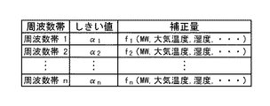
そこで、次に示す方法により、補正の基礎となる補正量データ(図2の表)の作成を行なう。
図2の表は、周波数帯、しきい値、補正値の各項目からなる。各項目について説明する。
周波数帯:周波数分析を行なった結果に基づいて、対応を行なう最小単位となる周波数領域である。
まず、圧力及び加速度の変動を調べる周波数範囲を決定する。例えば、図14においては、振動は、主に0〜5000Hzで発生していることから、周波数範囲を0〜5000Hzとする。そして、その周波数範囲を、適当な大きさの周波数帯に区切り、n個に分割する。例えば、50Hz毎に区切るとすると、n=100となる。なお、この周波数帯は、必ずしも一定の大きさである必要はない。
【0051】
しきい値:各周波数帯において、許容できる最高の振動強度を示す値である。
各周波数帯(周波数帯1〜n)に対して、圧力及び加速度の強度のしきい値(α1〜αn)を決定する。しきい値は、例えば、その周波数の振動により、共振する部材や構造があるか、損傷を受け易い部材や構造があるか、どのくらいの強度の振動まで許容できるかなどにより決定する。なお、このしきい値は、各周波数帯で、必ずしも共通の一定の大きさではない。
【0052】
補正値:ある周波数帯の振動を許容レベル以下にするために、通常の制御部11の制御信号に加える補正値の制御信号である。
補正値は、周波数帯(周波数帯1〜n)の各々に、プロセス量(例えば、発電電力、大気温度、湿度、各部での燃料流量及び圧力、各部での空気流量及び圧力、燃焼器での燃焼ガス温度、燃焼ガス流量、燃焼ガス圧力、圧縮機やタービンの回転数など)に基づいて、プロセス量の関数値として決定される。すなわち、周波数帯1〜nに対して、補正値の関数f1(プロセス量:発電電力、大気温度、湿度、…)〜fn(プロセス量:発電電力、大気温度、湿度、…)を対応させ、その関数の計算結果を補正値とする。周波数帯によりガスタービンに与える影響が異なることから、関数f1〜fnは、各周波数帯の各々について必ずしも同じにはならない。また、それに伴い、用いるプロセス量の種類も、必ずしも同じにはならない。
【0053】
関数f1〜fnは、ガスタービン2の構造及び使用する材料、運転条件などにより、様々に変わる。そのため、各ガスタービン毎に、設計(構造、材料など)及び試験運転時のデータ、過去の同タイプのガスタービンのデータなどから決定される。
【0054】
なお、しきい値については、各周波数帯(周波数帯1〜n)の各々について、一つである必要はない。すなわち、複数のしきい値を用意し、しきい値毎に危険レベルを設定する。そして、危険レベル毎に制御部11での対応を変える。それにより、しきい値レベルに応じて、運転状況を除除に変更でき、ガスタービン2への負担が軽減される。例えば、しきい値を2つ設け、危険レベルを2つ設定する。そして、最初のしきい値(すなわち危険レベル1)の場合には、補正値を小さくし、二番目のしきい値(すなわち危険レベル2)の場合には、アラームを発すると共に、補正値を大きくする。
【0055】
その例を示しているのが、図3である。図3においては、各周波数帯(周波数帯1〜n)に対して、しきい値が2個ずつ設定されている。例えば、周波数帯1については、α11及び、α12である。そして、それぞれのしきい値に対して、補正値f11(プロセス量)、f12(プロセス量)を対応させる。こうすることにより、振動の強度が大きくなった(しきい値を超えた)場合でも、急激な運転条件の変更を行なわずに振動の抑制に対応することが可能である。すなわち、ガスタービン2により負担の少ない、振動の抑制が可能となる。
【0056】
なお、図2又は図3に示すようなデータは、制御する部位(メイン燃料流量調整部5、パイロット燃料流量調整部6、バイパス空気流量調整部7、入口案内翼調整部8)及びそれらの各構成(各弁)の各々について作成する。本実施例では、パイロット燃料流量調整部6向けに作成する。
また、図2又は図3に示すようなデータは、圧力振動のみを用いても良いし、加速度振動のみを用いていも良いし、圧力振動及び加速度振動の両方を用いても良い。
【0057】
次に、ガスタービン2の運転時に、補正量を決定し、パイロット燃料流量を制御する方法について、図1、図2及び図12を参照して説明する。
▲1▼各運転前の段階(図12、開始の段階)で、図2(又は図3)に示すようなデータを準備する。準備方法は、既述の通りである。なお、このデータは、パイロット燃料補正部21内の図示しない記憶部に保存される。
【0058】
▲2▼次に、実際のガスタービン2の運転において、圧力変動測定部9及び加速度測定部10は、燃焼器111(−1〜m)での燃焼ガスの圧力変動及び燃焼器111(−1〜m)の加速度を測定する。そして、予め定められた時間毎に、それらの測定値が周波数解析部12へ出力される。出力されたデータは、ガスタービン制御部3の周波数解析部12により受信される(図12、ステップS1)。
【0059】
▲3▼ガスタービン制御部3の周波数解析部12は、測定値について、フーリエ解析などの手法により周波数分析を行なう。そして、図14に例示されるような周波数と振動強度(レベル)との関係を示すデータを得る。しかる後、そのデータを、予め設定された周波数帯に分割する(図12、ステップS2)。そうして得られた結果を、パイロット燃料補正部21の補正量決定部22へ出力する。
【0060】
▲4▼ガスタービン制御部3の補正量決定部22では、周波数解析部12で得られた周波数帯1〜nの各々の結果を、図示しない記憶部に保持された図2又は図3に示すデータ中の周波数帯1〜nの各々のしきい値αと比較する。そして、振動の強度が、しきい値αを超えていない場合には、補正値=0と決定する。振動の強度が、しきい値αを超えている場合(その周波数帯を異常周波数帯と呼ぶこととする)には、制御部11から出力されるプロセス量の値に基づいて、関数fを計算して補正値を決定する(図12、ステップS3)。決定した補正値は、加算部23へ出力する。
【0061】
▲5▼ガスタービン制御部3の加算部23では、補正量決定部22から出力される補正値と、制御部11から出力されるパイロット燃料流量調整部6を制御する制御信号とを加えて、新たにパイロット燃料流量調整部6を制御する制御信号として決定する(図12、ステップS4)。
【0062】
▲6▼ガスタービン制御部3の決定したパイロット燃料流量調整部6を制御する制御信号は、パイロット燃料流量調整部6へ出力する(図12、ステップS5)。
【0063】
▲7▼パイロット燃料流量調整部6では、加算部23から出力された制御信号に基づいて、然るべきパイロット燃料供給弁116(−1〜m)又は、パイロット燃料流量制御弁114を操作する。
【0064】
なお、上記▲1▼〜▲7▼のステップは、ガスタービン2の運転中、予め設定した時間毎に継続して行なわれる。
【0065】
加算部23からの出力による制御状況の例を、図13に示す。これは、補正値fP(プロセス量)とパイロット燃料供給弁の開度との関係を示す図である。縦軸は、パイロット燃料供給弁(116)開度、横軸は、ある周波数帯Pの補正値fP(プロセス量:MW、大気温度、…)である。また、Q0は、補正値が無い場合での、制御部11によるパイロット燃料供給弁116の開度を示す。この図から、補正値fPにより、パイロット燃料供給弁116の開度が、補正されている。また、その補正量は、プロセス量の値により変化する補正値fPに基づいて変化していることがわかる。
【0066】
なお、図13では、補正値fP(プロセス量)により、弁の開度が増加しているが、必ずしも増加する必要はない。装置の構成や、周波数帯により、減少させるようにしても良い。
【0067】
なお、他のメイン燃料流量、バイパス空気流量、入口案内翼による導入空気量の制御に関しては、予め設定した値になるように、フィードフォワード制御、フィードバック制御、PID制御などにより制御する。
【0068】
本発明により、パイロット燃料流量をガスタービン2で発生する圧力及び加速度の振動に対応して制御でき、圧力及び加速度の振動を抑制することが出来る。特に、発生する振動を周波数帯毎に分割して分析し、周波数帯毎に適切に対応を行なうので、効率的且つ適切に燃焼の安定性を向上させることが可能となる。
【0069】
(実施例2)
次に、上記ガスタービン2を有する本発明のガスタービン制御装置及びガスタービンシステムの第2の実施の形態について、図面を参照して説明する。
図4は、本発明であるガスタービン制御装置及びガスタービンシステムの実施例を示すブロック図である。ガスタービンシステム1は、ガスタービン2とガスタービン制御装置としてのガスタービン制御部3とを具備する。
【0070】
ガスタービン2は、プロセス量計測部4、メイン燃料流量調整部5、パイロット燃料流量調整部6、バイパス空気流量調整部7、入口案内翼調整部8、圧力変動測定部9及び加速度測定部10を有する。
【0071】
一方、ガスタービン制御部3は、制御部11、周波数解析部12、及び、補正部としてのバイパス空気補正部24を有する。バイパス空気補正部24は、補正量決定部25と加算部26とを有する
【0072】
本発明の本実施例では、ガスタービン2における圧力及び加速度の振動に対応して、パイロット燃料流量ではなく、バイパス空気流量の制御に補正量を導入する点が実施例1と異なる。すなわち、本実施例では、燃焼により発生する圧力及び加速度の振動を把握し、その内容を周波数分析(周波数解析部12)し、バイパス空気の流量調整の補正値を決定(バイパス空気補正部24)し、バイパス空気流量調整部7へ出力し、圧力の振動を抑制する。
【0073】
すなわち、ガスタービン制御部3は、ガスタービン2で発生する燃焼振動を把握する。そして、その周波数特性に応じて適切にガスタービン2の運転を制御(本実施例では、特にバイパス空気流量を適宜、振動状態に応じて変更)し、燃焼振動を抑制することが可能となる。
【0074】
図4の各部について説明する。
ガスタービン2は、実施例1で説明したものと同様であるので、その説明を省略する。
【0075】
一方、ガスタービン制御部3は、ガスタービン2で計測されたプロセス量や圧力、加速度のデータに基づいてガスタービン2を制御し、ガスタービン2において燃焼振動が発生しないようにする。
制御部11は、ガスタービン2で計測されたプロセス量に基づいて、メイン燃料流量調整部5、パイロット燃料流量調整部6及び入口案内翼調整部8を制御信号を出力して制御する。また、通常のバイパス空気流量調整部7を制御する信号を、バイパス空気補正部24(後述)へ出力し、バイパス空気補正部24によるバイパス空気流量調整部7の制御を補佐する。メイン燃料流量調整部5、パイロット燃料流量調整部6及び入口案内翼調整部8の制御は、フィードフォワード法による制御、フィードバック法による制御、PID法による制御などで行なう。周波数解析部12は、分析結果を、バイパス空気補正部24に出力する以外は実施例1と同様である。
【0076】
補正部としての、バイパス空気補正部24は、圧力又は加速度の周波数帯別分析結果とプロセス量とに基づいて、補正量を算出する。そして、制御部11からのバイパス空気流量調整部7を制御する制御信号にその補正量を加えて、バイパス空気流量調整部7へ出力する。制御部11に含まれていても良い。
補正量決定部25は、周波数解析部12からの圧力又は加速度の周波数帯別分析結果と、制御部11からのプロセス量とに基づいて、自身が有する補正量決定表(図2、図3など)から、バイパス空気流量調整部7を制御する制御信号に対する補正量を決定する。決定した補正量は、加算部26へ出力する。
加算部26は、制御部11からのバイパス空気流量調整部7を制御する制御信号に、補正量決定部25で決定された補正量を加えて、バイパス空気流量調整部7を制御する制御信号として、バイパス空気流量調整部7へ出力する。
【0077】
次に、本発明のガスタービン制御装置及びガスタービンシステムの実施の形態の動作について、図面を参照して説明する。
ここで、ガスタービン運転時の制御に使用する補正の基礎となる補正量データ(図2又は図3のようなデータ)の決定方法については、実施例1と同様であるので、その説明を省略する。
【0078】
なお、図2又は図3に示すようなデータは、制御する部位(メイン燃料流量調整部5、パイロット燃料流量調整部6、バイパス空気流量調整部7、入口案内翼調整部8)及びそれらの各構成(各弁)の各々について作成する。本実施例では、バイパス空気流量調整部7向けに作成する。
また、図2又は図3に示すようなデータは、圧力振動のみを用いても良いし、加速度振動のみを用いていも良いし、圧力振動及び加速度振動の両方を用いても良い。
【0079】
次に、ガスタービン2の運転時に、補正量を決定し、バイパス空気流量を制御する方法について、図4、図2及び図12を参照して説明する。
▲1▼各運転前の段階(図12、開始の段階)で、図2(又は図3)に示すようなデータを準備する。準備方法は、既述の通りである。なお、このデータは、バイパス空気補正部24内の図示しない記憶部に保存される。
【0080】
▲2▼次に、実際のガスタービン2の運転において、圧力変動測定部9及び加速度測定部10は、燃焼器111(−1〜m)での燃焼ガスの圧力変動及び燃焼器111(−1〜m)の加速度を測定する。そして、予め定められた時間毎に、それらの測定値が周波数解析部12へ出力される。出力されたデータは、ガスタービン制御部3の周波数解析部12により受信される(図12、ステップS1)。
【0081】
▲3▼ガスタービン制御部3の周波数解析部12は、測定値について、フーリエ解析などの手法により周波数分析を行なう。そして、図14に例示されるような周波数と振動強度(レベル)との関係を示すデータを得る。しかる後、そのデータを、予め設定された周波数帯に分割する(図12、ステップS2)。そうして得られた結果を、バイパス空気補正部24の補正量決定部25へ出力する。
【0082】
▲4▼ガスタービン制御部3の補正量決定部25では、周波数解析部12で得られた周波数帯1〜nの各々の結果を、図示しない記憶部に保持された図2又は図3に示すデータ中の周波数帯1〜nの各々のしきい値αと比較する。そして、振動の強度が、しきい値αを超えていない場合には、補正値=0と決定する。振動の強度が、しきい値αを超えている場合(この周波数帯を異常周波数帯ということとする)には、制御部11から出力されるプロセス量の値に基づいて、関数fを計算して補正値を決定する(図12、ステップS3)。決定した補正値は、加算部26へ出力する。
【0083】
▲5▼ガスタービン制御部3の加算部26では、補正量決定部25から出力される補正値と、制御部11から出力されるバイパス空気流量調整部7を制御する制御信号とを加えて、新たにバイパス空気流量調整部7を制御する制御信号として決定する(図12、ステップS4)。
【0084】
▲6▼ガスタービン制御部3の決定したバイパス空気流量調整部7を制御する制御信号は、バイパス空気流量調整部7へ出力される(図12、ステップS5)。
【0085】
▲7▼バイパス空気流量調整部7では、加算部26から出力された制御信号に基づいて、然るべきバイパス弁118(−1〜m)を操作する。
【0086】
なお、上記▲1▼〜▲7▼のステップは、ガスタービン2の運転中、予め設定した時間毎に継続して行なわれる。
【0087】
なお、他のメイン燃料流量、パイロット燃料流量、入口案内翼による導入空気量の制御に関しては、予め設定した値になるように、フィードフォワード制御、フィードバック制御、PID制御などにより制御する。
【0088】
本発明により、バイパス空気流量をガスタービン2で発生する圧力及び加速度の振動に対応して制御でき、圧力及び加速度の振動を抑制することが出来る。特に、発生する振動を周波数帯毎に分割して分析し、周波数帯毎に適切に対応を行なうので、効率的且つ適切に燃焼の安定性を向上させることが可能となる。
【0089】
(実施例3)
次に、上記ガスタービン2を有する本発明のガスタービン制御装置及びガスタービンシステムの第3の実施の形態について、図面を参照して説明する。
図5は、本発明であるガスタービン制御装置及びガスタービンシステムの実施例を示すブロック図である。ガスタービンシステム1は、ガスタービン2とガスタービン制御装置としてのガスタービン制御部3とを具備する。
【0090】
ガスタービン2は、プロセス量計測部4、メイン燃料流量調整部5、パイロット燃料流量調整部6、バイパス空気流量調整部7、入口案内翼調整部8、圧力変動測定部9及び加速度測定部10を有する。
【0091】
一方、ガスタービン制御部3は、制御部11、周波数解析部12、及び、入口案内翼補正部27を有する。入口案内翼補正部27は、補正量決定部28と加算部29とを有する
【0092】
本発明の本実施例では、ガスタービン2における圧力及び加速度の振動に対応して、パイロット燃料流量やバイパス空気流量ではなく、入口案内翼102の制御すなわち圧縮機101に導入する空気の制御に、補正量を導入する点が実施例1及び実施例2と異なる。すなわち、本実施例では、燃焼により発生する圧力及び加速度の振動を把握し、その内容を周波数分析(周波数解析部12)し、入口案内翼102の制御すなわち圧縮機101に導入する空気の流量調整の補正値を決定(入口案内翼補正部27)し、入口案内翼調整部8へ出力し、圧力の振動を抑制する。
【0093】
すなわち、ガスタービン制御部3は、ガスタービン2で発生する燃焼振動を把握する。そして、その周波数特性に応じて適切にガスタービン2の運転を制御(本実施例では、特に入口案内翼の状態を適宜、振動状態に応じて変更)し、燃焼振動を抑制することが可能となる。
【0094】
図5の各部について説明する。
ガスタービン2は、実施例1で説明したものと同様であるので、その説明を省略する。
【0095】
一方、ガスタービン制御部3は、ガスタービン2で計測されたプロセス量や圧力、加速度のデータに基づいてガスタービン2を制御し、ガスタービン2において燃焼振動が発生しないようにする。
制御部11は、ガスタービン2で計測されたプロセス量に基づいて、メイン燃料流量調整部5、パイロット燃料流量調整部6及びバイパス空気流量調整部7を制御信号を出力して制御する。また、通常の入口案内翼調整部8を制御する信号を、入口案内翼補正部27(後述)へ出力し、入口案内翼補正部27による入口案内翼調整部8の制御を補佐する。メイン燃料流量調整部5、パイロット燃料流量調整部6及びバイパス空気流量調整部7の制御は、フィードフォワード法による制御、フィードバック法による制御、PID法による制御などで行なう。
周波数解析部12は、分析結果を、入口案内翼補正部27に出力する以外は実施例1と同様である。
【0096】
入口案内翼補正部27は、圧力又は加速度の周波数帯別分析結果とプロセス量に基づいて、補正量を算出する。そして、制御部11からの入口案内翼調整部8を制御する信号にその補正量を加えて、入口案内翼調整部8へ出力する。制御部11に含まれていても良い。
補正量決定部28は、周波数解析部12からの圧力又は加速度の周波数帯別分析結果と、制御部11からのプロセス量とに基づいて、自身が有する補正量決定表(図2、図3など)から、入口案内翼調整部8を制御する制御信号に対する補正量を決定する。決定した補正量は、加算部29へ出力する。
加算部29は、制御部11からの入口案内翼調整部8を制御する制御信号に、補正量決定部28で決定された補正量を加えて、入口案内翼調整部8を制御する制御信号として、入口案内翼調整部8へ出力する。
【0097】
次に、本発明のガスタービン制御装置及びガスタービンシステムの実施の形態の動作について、図面を参照して説明する。
ここで、ガスタービン運転時の制御に使用する補正の基礎となる補正量データ(図2又は図3のようなデータ)の決定方法については、実施例1と同様であるので、その説明を省略する。
【0098】
なお、図2又は図3に示すようなデータは、制御する部位(メイン燃料流量調整部5、パイロット燃料流量調整部6、バイパス空気流量調整部7、入口案内翼調整部8)及びそれらの各構成(各弁)の各々について作成する。本実施例では、入口案内翼調整部8向けに作成する。
また、図2又は図3に示すようなデータは、圧力振動のみを用いても良いし、加速度振動のみを用いていも良いし、圧力振動及び加速度振動の両方を用いても良い。
【0099】
次に、ガスタービン2の運転時に、補正量を決定し、入口案内翼を制御する方法について、図5、図2及び図12を参照して説明する。
▲1▼各運転前の段階(図12、開始の段階)で、図2(又は図3)に示すようなデータを準備する。準備方法は、既述の通りである。なお、このデータは、入口案内翼補正部27内の図示しない記憶部に保存される。
【0100】
▲2▼次に、実際のガスタービン2の運転において、圧力変動測定部9及び加速度測定部10は、燃焼器111(−1〜m)での燃焼ガスの圧力変動及び燃焼器111(−1〜m)の加速度を測定する。そして、予め定められた時間毎に、それらの測定値が周波数解析部12へ出力される。出力されたデータは、ガスタービン制御部3の周波数解析部12により受信される(図12、ステップS1)。
【0101】
▲3▼ガスタービン制御部3の周波数解析部12は、測定値について、フーリエ解析などの手法により周波数分析を行なう。そして、図14に例示されるような周波数と振動強度(レベル)との関係を示すデータを得る。しかる後、そのデータを、予め設定された周波数帯に分割する(図12、ステップS2)。そうして得られた結果を、入口案内翼補正部27の補正量決定部28へ出力する。
【0102】
▲4▼ガスタービン制御部3の補正量決定部28では、周波数解析部12で得られた周波数帯1〜nの各々の結果を、図示しない記憶部に保持された図2又は図3に示すデータ中の周波数帯1〜nの各々のしきい値αと比較する。そして、振動の強度が、しきい値αを超えていない場合には、補正値=0と決定する。振動の強度が、しきい値αを超えている場合には、制御部11から出力されるプロセス量の値に基づいて、関数fを計算して補正値を決定する(図12、ステップS3)。決定した補正値は、加算部29へ出力する。
【0103】
▲5▼ガスタービン制御部3の加算部29では、補正量決定部28から出力される補正値と、制御部11から出力される入口案内翼調整部8を制御する制御信号とを加えて、新たに入口案内翼調整部8を制御する制御信号として決定する(図12、ステップS4)。
【0104】
▲6▼ガスタービン制御部3の決定した入口案内翼調整部8を制御する制御信号は、入口案内翼調整部8へ出力される(図12、ステップS5)。
【0105】
▲7▼入口案内翼調整部8では、加算部26から出力された制御信号に基づいて、入口案内翼102を操作する。
【0106】
なお、上記▲1▼〜▲7▼のステップは、ガスタービン2の運転中、予め設定した時間毎に継続して行なわれる。
【0107】
なお、他のメイン燃料流量、パイロット燃料流量、バイパス空気流量の制御に関しては、予め設定した値になるように、フィードフォワード制御、フィードバック制御、PID制御などにより制御する。
【0108】
本発明により、入口案内翼102により制御される空気の流量をガスタービン2で発生する圧力及び加速度の振動に対応して制御でき、圧力及び加速度の振動を抑制することが出来る。特に、発生する振動を周波数帯毎に分割して分析し、周波数帯毎に適切に対応を行なうので、効率的且つ適切に燃焼の安定性を向上させることが可能となる。
【0109】
(実施例4)
次に、上記ガスタービン2を有する本発明のガスタービン制御装置及びガスタービンシステムの第4の実施の形態について、図面を参照して説明する。
図6は、本発明であるガスタービン制御装置及びガスタービンシステムの実施例を示すブロック図である。ガスタービンシステム1は、ガスタービン2とガスタービン制御装置としてのガスタービン制御部3とを具備する。
【0110】
ガスタービン2は、プロセス量計測部4、メイン燃料流量調整部5、パイロット燃料流量調整部6、バイパス空気流量調整部7、入口案内翼調整部8、圧力変動測定部9及び加速度測定部10を有する。
【0111】
一方、ガスタービン制御部3は、制御部11、周波数解析部12、データベース15及び、補正量決定部31と加算部23と加算部26と加算部29と加算部32とを有する補正部としての全補正部30を有する。
【0112】
本発明の本実施例では、ガスタービン2における圧力及び加速度の振動に対応して、メイン燃料流量、パイロット燃料流量、バイパス空気流量及び入口案内翼102の4つの制御に、補正量を導入する点が実施例1〜実施例3と異なる。
【0113】
また、新規のガスタービン2における、振動強度と、第2燃料流量としてのメイン燃料流量及びパイロット燃料流量、第2空気流量としてのバイパス空気流量及び入口案内翼102からの空気流量との関係のデータを有している。そして、それらのデータと運転中の実機の振動強度のデータとを比較し、実機の状態が新規のガスタービン2におけるどの状態であるかを判断する。そして、その判断に基づいて、流量の較正を行ない、補正量を調整する点もまた実施例1〜実施例3と異なる。
【0114】
すなわち、ガスタービン制御部3は、ガスタービン2で発生する燃焼振動を把握する。そして、その周波数特性に応じて適切にガスタービン2の運転を制御(本実施例では、メイン燃料流量、パイロット燃料流量、バイパス空気流量、入口案内翼の状態を適宜、振動状態に応じて変更)し、加えて、経年変化等の影響を補正して、燃焼振動を抑制することが可能となる。
【0115】
図6の各部について説明する。
ガスタービン2は、実施例1で説明したものと同様であるので、その説明を省略する。
【0116】
一方、ガスタービン制御部3は、ガスタービン2で計測されたプロセス量や圧力、加速度のデータに基づいてガスタービン2を制御し、ガスタービン2において燃焼振動が発生しないようにする。
制御部11は、ガスタービン2で計測されたプロセス量に基づいて、メイン燃料流量調整部5、パイロット燃料流量調整部6、バイパス空気流量調整部7及び入口案内翼調整部8を制御する制御信号を、全補正部30(後述)へ出力し、全補正部30によるメイン燃料流量調整部5、パイロット燃料流量調整部6、バイパス空気流量調整部7及び入口案内翼調整部8への制御を補佐する。
周波数解析部12は、分析結果を、全補正部30に出力する以外は実施例1と同様である。
【0117】
データベース15は、新規のガスタービン2における、振動強度と、メイン燃料流量、パイロット燃料流量、バイパス空気流量及び入口案内翼102からの空気流量との関係のデータ(運転情報データともいう)を有している。そのデータについて、図15を参照して説明する。
図15において、周波数帯1〜nは、図2(又は図3)において説明した周波数帯と同様である。制御量Xは、第2燃料流量としてのメイン燃料流量及びパイロット燃料流量、第2空気流量としてのバイパス空気流量及び入口案内翼102からの空気流量のいずれか一つを表している。図15の表で示されるデータは、上記4種類の燃料及び空気(メイン燃料、パイロット燃料、バイパス空気及び入口案内翼102からの空気、以下同じ)に対して存在する。流量帯a1、a2、…、aLは、燃料又は空気の流量の範囲を示す。例えば、0≦a1<5Nm3/min.、5≦a2<10Nm3/min.、…、45≦aL<50Nm3/min.などである。新規周波数帯別分析結果としての振動強度は、ある流量帯の運転状態において、ある周波数帯の振動の強度を表している。例えば、流量帯a2の運転状態において、周波数帯2の振動の強度は、A22で示す値となる。この振動強度には、具体的な数値が入る。
【0118】
図15は、新規のガスタービン2の設計時のデータ、試運転時のデータ等に基づいて決定される。そして、上記4種類の燃料及び空気に対して、1種類を変化させ、他の3種類の流量を固定した図15のようなデータが作成される。また、他の3種類の流量の固定は、複数の値において行なわれ、その組み合わせにおいて、運転条件を全て網羅できるようにすることが望ましい。
【0119】
補正部としての全補正部30は、圧力又は加速度の周波数帯別分析結果とプロセス量に基づいて、補正量を算出する。そして、制御部11からのメイン燃料流量調整部5、パイロット燃料流量調整部6、バイパス空気流量調整部7及び入口案内翼調整部8を制御する制御信号にその補正量を加えて、各部へ出力する。制御部11に含まれていても良い。
補正量決定部31は、周波数解析部12からの圧力又は加速度の周波数帯別分析結果と、データベースの有する4種類の燃料及び空気での振動強度データとから、現状のガスタービン2の運転状態を新規のガスタービン2に当てはめる。すなわち、図15で例示されるデータとの一致を調べる。そして、その結果に基づいて、その新規のガスタービン2用に設定された自身が有する補正量決定表(図2、図3など)から、メイン燃料流量調整部5、パイロット燃料流量調整部6、バイパス空気流量調整部7及び入口案内翼調整部8を制御する信号に対する補正量を決定する。決定した補正量は、加算部23、加算部26、加算部29及び加算部32へ出力する。
加算部23、加算部26、加算部29及び加算部32は、制御部11からのメイン燃料流量調整部5、パイロット燃料流量調整部6、バイパス空気流量調整部7及び入口案内翼調整部8を制御する制御信号に、補正量決定部31で決定された補正量を加えて、メイン燃料流量調整部5、パイロット燃料流量調整部6、バイパス空気流量調整部7及び入口案内翼調整部8を制御する制御信号として、メイン燃料流量調整部5、パイロット燃料流量調整部6、バイパス空気流量調整部7及び入口案内翼調整部8へ出力する。
【0120】
次に、本発明のガスタービン制御装置及びガスタービンシステムの実施の形態の動作について、図面を参照して説明する。
ここで、ガスタービン運転時の制御に使用する補正の基礎となる補正量データ(図2又は図3のようなデータ)の決定方法については、新規のガスタービン2について行なわれること以外は、実施例1と同様であるので、その説明を省略する。ただし、実施例1においても、新規のガスタービン2について行なわれることもある。
【0121】
なお、図2又は図3に示すようなデータは、制御する部位(メイン燃料流量調整部5、パイロット燃料流量調整部6、バイパス空気流量調整部7、入口案内翼調整部8)及びそれらの各構成(各弁)の各々について作成する。本実施例では、上記全ての制御する部位向けに作成する。
また、図2又は図3に示すようなデータは、圧力振動のみを用いても良いし、加速度振動のみを用いていも良いし、圧力振動及び加速度振動の両方を用いても良い。
【0122】
次に、ガスタービン2の運転時に、補正量を決定し、メイン燃料流量調整部5、パイロット燃料流量調整部6、バイパス空気流量調整部7及び入口案内翼調整部8を制御する方法について、図6、図2、図12及び図15を参照して説明する。
▲1▼各運転前の段階(図12、開始の段階)で、図2(又は図3)及び図15に示すようなデータを準備する。これらは、新規のガスタービン2用に作成される。準備方法は、既述の通りである。なお、このデータは、全補正部30内の図示しない記憶部に保存される。
【0123】
▲2▼次に、実際のガスタービン2の運転において、圧力変動測定部9及び加速度測定部10は、燃焼器111(−1〜m)での燃焼ガスの圧力変動及び燃焼器111(−1〜m)の加速度を測定する。そして、予め定められた時間毎に、それらの測定値が周波数解析部12へ出力される。出力されたデータは、ガスタービン制御部3の周波数解析部12により受信される(図12、ステップS1)。
【0124】
▲3▼ガスタービン制御部3の周波数解析部12は、測定値について、フーリエ解析などの手法により周波数分析を行なう。そして、図14に例示されるような周波数と振動強度(レベル)との関係を示すデータを得る。しかる後、そのデータを、予め設定された周波数帯に分割する(図12、ステップS2)。そうして得られた結果を、全補正部30の補正量決定部31へ出力する。
【0125】
▲4▼ガスタービン制御部3の補正量決定部31では、周波数解析部12で得られた各周波数帯(1〜n)の振動強度を、図15に例示されるデータ(データベース15に記憶された周波数帯と、メイン燃料、パイロット燃料、バイパス空気及び入口案内翼102からの空気の各流量帯と、振動強度との関係のデータ、以降、運転情報データという)と比較する。そして、各周波数帯の振動強度と、運転情報データとが良い一致を示す場合の運転状態(4種類の燃料及び空気流量)を見出す。ここで、良い一致とは、例えば、振動強度の相違が±10%以内の場合などである。
【0126】
続いて、見出された運転状態(4種類の燃料及び空気流量)と、実際に運転しているガスタービン2の4種類の燃料及び空気流量とを比較して、その差分を計算する。そして、その差分が許容範囲内(例えば±2%以内)であるならば、特別な対応は行なわない。
その場合には、補正量決定部31では、図示しない記憶部に保持された図2又は図3に示すデータ中の周波数帯1〜nの各々のしきい値αと比較する。そして、振動の強度が、しきい値αを超えていない場合には、補正値=0と決定する。振動の強度が、しきい値αを超えている場合には、制御部11から出力されるプロセス量(例えば、発電電力、大気温度、湿度、各部での燃料流量及び圧力、各部での空気流量及び圧力、燃焼器での燃焼ガス温度、燃焼ガス流量、燃焼ガス圧力、圧縮機やタービンの回転数など)の値に基づいて、関数fを計算して補正値を決定する(図12、ステップS3)。決定した補正値は、加算部23、加算部26、加算部29及び加算部32へ出力する。
【0127】
また、4種類の燃料又は空気流量のいずれかの差分が許容範囲を超えている(例えば±2%を超える)場合であるならば、その流量の差分に基づいて、該当する燃料又は空気流量を較正する。そして、その値を補正量決定部31の図示しない記憶部内に記憶する。そして、それ以降の制御に関して、この較正値を用いることとする。また、その較正値を制御部11へ出力し、そこで較正値を用いる用にすることも可能である。
その後の工程は、流量が許容範囲を超えていない場合と同様であるので、説明を省略する。
【0128】
図2(又は図3)から求められる補正値は、各周波数帯(周波数帯1〜n)毎に、プロセス量に基づいて決定されるため、燃料又は空気流量の相違は、補正値のずれを生じさせる。そのため、的確な振動抑制の制御が出来なくなる恐れがある。しかし、上記較正により、経年変化などの原因により、流量の相違が生じても適性に補正値を決定することが可能となる。
【0129】
▲5▼ガスタービン制御部3の加算部23、加算部26、加算部29及び加算部32では、補正量決定部31から出力される補正値と、制御部11から出力されるメイン燃料流量調整部5、パイロット燃料流量調整部6、バイパス空気流量調整部7、入口案内翼調整部8を制御する制御信号とを加えて、新たにメイン燃料流量調整部5、パイロット燃料流量調整部6、バイパス空気流量調整部7、入口案内翼調整部8を制御する制御信号として決定する(図12、ステップS4)。
【0130】
▲6▼ガスタービン制御部3の決定したメイン燃料流量調整部5、パイロット燃料流量調整部6、バイパス空気流量調整部7、入口案内翼調整部8を制御する制御信号は、メイン燃料流量調整部5、パイロット燃料流量調整部6、バイパス空気流量調整部7、入口案内翼調整部8へ出力される(図12、ステップS5)。
【0131】
▲7▼メイン燃料流量調整部5、パイロット燃料流量調整部6、バイパス空気流量調整部7、入口案内翼調整部8では、加算部26から出力された制御信号に基づいて、然るべきメイン燃料供給弁115(−1〜m)又はメイン燃料流量制御弁113、然るべきパイロット燃料供給弁116(−1〜m)又はパイロット燃料流量制御弁114、然るべきバイパス弁118(−1〜m)、入口案内翼102を操作する。
【0132】
なお、上記▲1▼〜▲7▼のステップは、ガスタービン2の運転中、予め設定した時間毎に継続して行なわれる。
【0133】
本発明により、メイン燃料供給弁115(−1〜m)、メイン燃料流量制御弁113、パイロット燃料供給弁116(−1〜m)、パイロット燃料流量制御弁114、バイパス弁118(−1〜m)、入口案内翼102により制御される空気の流量をガスタービン2で発生する圧力及び加速度の振動に対応して制御でき、圧力及び加速度の振動を抑制することが出来る。特に、発生する振動を周波数帯毎に分割して分析し、周波数帯毎に適切に対応を行なうので、効率的且つ適切に燃焼の安定性を向上させることが可能となる。
【0134】
また、経年変化などにより、実際の燃料又は空気の流量が、制御部11等の認識と相違する自体が発生しても、データベースのデータを用いることにより、自己較正が可能となる。そして、長期的に安定的に燃焼を継続することが可能となる。
【0135】
(実施例5)
次に、上記ガスタービン2を有する本発明のガスタービン制御装置及びガスタービンシステムの第5の実施の形態について、図面を参照して説明する。
図7は、本発明であるガスタービン制御装置及びガスタービンシステムの実施例を示すブロック図である。ガスタービンシステム1は、ガスタービン2とガスタービン制御装置としてのガスタービン制御部3とを具備する。
【0136】
ガスタービン2は、プロセス量計測部4、メイン燃料流量調整部5、パイロット燃料流量調整部6、バイパス空気流量調整部7、入口案内翼調整部8、圧力変動測定部9及び加速度測定部10を有する。
【0137】
一方、ガスタービン制御部3は、制御部11、周波数解析部12、試行決定部16及び、補正量決定部31と加算部23と加算部26と加算部29と加算部32とを有する補正部としての全補正部33を有する。
【0138】
本発明の本実施例では、ガスタービン2における圧力及び加速度の振動に対応して、メイン燃料流量、パイロット燃料流量、バイパス空気流量及び入口案内翼102の4つの制御に、補正量を導入する点が実施例1〜実施例3と異なる。
【0139】
また、運転中のガスタービン2における、運転条件の一部を少しずつ変更し、振動強度と変更した運転条件との関係を求める。そして、複数の運転条件の変更の結果から、最適(振動強度が極小となる)な運転条件を決定する点もまた実施例1〜実施例3と異なる。
【0140】
すなわち、ガスタービン制御部3は、ガスタービン2で発生する燃焼振動を把握する。そして、その周波数特性に応じて適切にガスタービン2の運転を制御(本実施例では、メイン燃料流量、パイロット燃料流量、バイパス空気流量、入口案内翼の状態を適宜、振動状態に応じて変更)し、加えて、燃焼振動が極小となる運転条件を自ら見出し、燃焼振動を抑制することが可能となる。
【0141】
図7の各部について説明する。
ガスタービン2は、実施例1で説明したものと同様であるので、その説明を省略する。
【0142】
一方、ガスタービン制御部3は、ガスタービン2で計測されたプロセス量や圧力、加速度のデータに基づいてガスタービン2を制御し、ガスタービン2において燃焼振動が発生しないようにする。
制御部11は、ガスタービン2で計測されたプロセス量に基づいて、メイン燃料流量調整部5、パイロット燃料流量調整部6、バイパス空気流量調整部7及び入口案内翼調整部8を制御する制御信号を、全補正部33(後述)へ出力し、全補正部33によるメイン燃料流量調整部5、パイロット燃料流量調整部6、バイパス空気流量調整部7及び入口案内翼調整部8への制御を補佐する。
周波数解析部12は、分析結果を、全補正部33に出力する以外は実施例1と同様である。
【0143】
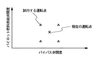
試行決定部16は、現在運転しているガスタービン2における運転条件(メイン燃料供給弁115(−1〜m)、メイン燃料流量制御弁113、パイロット燃料供給弁116(−1〜m)、パイロット燃料流量制御弁114、バイパス弁118(−1〜m)の弁の開度、入口案内翼102の角度)を変動させて、振動強度が極小となる運転条件を見出すための、運転変更して試行運転を行なう運転条件の決定及び実行を行なう。図8を参照して、運転変更の決定及び実行について説明する。
【0144】
図8は、横軸がバイパス弁118(−1〜m)の開度、縦軸がパイロット燃料供給弁116(−1〜m)の開度を示している。ガスタービン2が、例えば、図8に示す×印の点の条件で運転している場合、図中△で示す運転条件(4点)を試行運転する点とする。実際の運転条件と試行する運転条件との相違幅は、予め設定さられた幅(例えば、流量の±2%、など)で行なう。試行決定部16は、相違幅(例えば、±0.01Nm3/min.)を決定し、補正量決定部31へ出力する。
【0145】
補正部としての全補正部33は、圧力又は加速度の周波数帯別分析結果とプロセス量と相違幅とに基づいて、補正量を算出する。そして、制御部11からのメイン燃料流量調整部5、パイロット燃料流量調整部6、バイパス空気流量調整部7及び入口案内翼調整部8を制御する制御信号にその補正量を加えて、各部へ出力する。制御部11に含まれていても良い。
補正量決定部31は、試行決定部16からの相違幅を実現する補正値を求め、加算部23、加算部26、加算部29及び加算部32へ出力する。なお、本実施例においては、実施例1〜実施例3にあるような周波数解析部12からの周波数分析結果に基づく運転条件の変更は、一時中断とする。
加算部23、加算部26、加算部29及び加算部32は、制御部11からのメイン燃料流量調整部5、パイロット燃料流量調整部6、バイパス空気流量調整部7及び入口案内翼調整部8を制御する制御信号に、補正量決定部31で決定された補正量を加えて、メイン燃料流量調整部5、パイロット燃料流量調整部6、バイパス空気流量調整部7及び入口案内翼調整部8を制御する制御信号として、メイン燃料流量調整部5、パイロット燃料流量調整部6、バイパス空気流量調整部7及び入口案内翼調整部8へ出力する。
【0146】
次に、本発明のガスタービン制御装置及びガスタービンシステムの実施の形態の動作について、図面を参照して説明する。
(1)本実施例では、実施例1〜実施例3で示すようなガスタービン2の運転が行なわれている。その運転状態は、例えば、図8の×印で示すような条件である(図16、開始の段階)。
【0147】
(2)次に、試行点決定部16は、図8の例では、×印で示す運転条件から少しずれた図8の△印で示すような試行する運転条件(以下、試行点という)を決定する。しかる後、試行点と現状の運転条件との差分(図8の例では、現状の運転条件におけるバイパス弁118及びパイロット燃料供給弁116の開度と、試行点の各弁の開度との差分)を、補正量決定部31へ出力する(図16、ステップS11)。
【0148】
(3)補正量決定部31は、試行点決定部16からの運転条件の差分を、補正量に変換して、決定する(図16、ステップS12)。決定した補正値は、加算部23、加算部26、加算部29及び加算部32へ出力する。
【0149】
(4)ガスタービン制御部3の加算部23、加算部26、加算部29及び加算部32では、補正量決定部31から出力される補正値と、制御部11から出力されるメイン燃料流量調整部5、パイロット燃料流量調整部6、バイパス空気流量調整部7、入口案内翼調整部8を制御する制御信号とを加えて、新たにメイン燃料流量調整部5、パイロット燃料流量調整部6、バイパス空気流量調整部7、入口案内翼調整部8を制御する制御信号として決定する(図16、ステップS13)。
【0150】
(5)ガスタービン制御部3の決定したメイン燃料流量調整部5、パイロット燃料流量調整部6、バイパス空気流量調整部7、入口案内翼調整部8を制御する制御信号は、メイン燃料流量調整部5、パイロット燃料流量調整部6、バイパス空気流量調整部7、入口案内翼調整部8へ出力される(図16、ステップS14)。
【0151】
(6)メイン燃料流量調整部5、パイロット燃料流量調整部6、バイパス空気流量調整部7、入口案内翼調整部8では、加算部26から出力された制御信号に基づいて、然るべきメイン燃料供給弁115(−1〜m)又はメイン燃料流量制御弁113、然るべきパイロット燃料供給弁116(−1〜m)又はパイロット燃料流量制御弁114、然るべきバイパス弁118(−1〜m)、入口案内翼102を操作する。
操作の結果、ガスタービン2の運転状態が変化し、振動の強度が変化する。圧力変動測定部9及び加速度測定部10は、燃焼器111(−1〜m)での燃焼ガスの圧力変動及び燃焼器111(−1〜m)の加速度を測定する。そして、それらの測定値が周波数解析部12へ出力される。出力されたデータは、ガスタービン制御部3の周波数解析部12により受信される(図16、ステップS15)。
【0152】
(7)ガスタービン制御部3の周波数解析部12は、測定値について、フーリエ解析などの手法により周波数分析を行なう。そして、図14に例示されるような周波数と振動強度(レベル)との関係を示すデータを得る。しかる後、そのデータを、予め設定された周波数帯に分割する(図16、ステップS16)。そうして得られた結果を、試行点決定部16へ出力する。
【0153】
(8)上記▲2▼〜▲8▼までのプロセスを、試行点の数だけ繰り返す(図16、ステップS17)。
【0154】
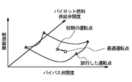
(9)全ての試行点における運転及び周波数解析が終了した後、試行点決定部16において、最適運転点を決定する。図9を参照して、最適運転点の決定方法について説明する。
図9において、横軸は、バイパス弁118(−1〜m)の開度であり、縦軸は、周波数解析により得られる振動強度である。図中×印は、ガスタービン2の試行点運転前の初期の運転条件での振動強度である。また、△印は、試行点の運転条件での振動強度である。そして、△印間を結ぶ曲線は、△印及び×印の点の測定値に基づいて予測した曲面を示したものである。この時、他の運転条件から決定されるバイパス弁118(−1〜m)の開度の変更範囲の制限と、図9で例示される試行結果とから、○印のような最適点が決定される(図16、ステップS18)。
最終的に、決定された最適点になるように、運転条件が補正される。
【0155】
本発明により、ガスタービン制御装置が自ら、振動が少ない運転条件を試行により見出すので、振動の抑制された安定した燃焼の運転が可能となる。そして、ガスタービンの長寿命化や、メンテナンスコストの低減等を図ることが出来る。
【0156】
また、経年変化などにより、実際の燃料又は空気の流量が、制御部11等の認識と相違する自体が発生しても、試行運転により最適な運転点を見出して、運転条件を改定するので、経年変化の影響を受け難い。
【0157】
(実施例6)
次に、上記ガスタービン2を有する本発明のガスタービン遠隔監視システムの実施の形態について、図面を参照して説明する。
図10は、本発明であるガスタービン遠隔監視システムの実施例を示すブロック図である。ガスタービン遠隔監視システムは、ガスタービンシステム1と、遠隔監視部20とを具備する。また、ガスタービンシステム1は、ガスタービン2とガスタービン制御装置としてのガスタービン制御部3とを具備する。
【0158】
ガスタービン2は、プロセス量計測部4、メイン燃料流量調整部5、パイロット燃料流量調整部6、バイパス空気流量調整部7、入口案内翼調整部8、圧力変動測定部9及び加速度測定部10を有する。
一方、ガスタービン制御部3は、制御部11、周波数解析部12及び通信部17を具備する。
そして、遠隔監視部20は、データベース35、全補正部34及び通信部18を具備する。
【0159】
本発明の本実施例では、ガスタービン2における圧力及び加速度の振動に対して、遠隔地にある遠隔監視部20が、その対応を行なう点が、実施例1〜実施例4と異なる。すなわち、まず、ガスタービン2での振動に関わるデータをガスタービン制御部3より通信回線を経由して取得する。全補正部34は、受信した振動データと、データベース35のデータとを参照して、メイン燃料流量、パイロット燃料流量、バイパス空気流量及び入口案内翼102への制御の補正量を算出する。そして、通信回線を介してガスタービン制御部3へ指令を送信することにより、振動を抑制する。
【0160】
すなわち、遠隔監視部20は、ガスタービン制御部3からの通信によりガスタービン2で発生する燃焼振動を把握する。そして、その周波数特性に応じて適切にガスタービン2の運転を制御(本実施例では、メイン燃料流量、パイロット燃料流量、バイパス空気流量、入口案内翼の状態を適宜、振動状態に応じて変更)する信号を発信し、遠隔地から燃焼振動を抑制することが可能となる。
【0161】
図10の各部について説明する。
ガスタービン2は、実施例1で説明したものと同様であるので、その説明を省略する。
【0162】
一方、ガスタービン制御部3は、ガスタービン2で計測されたプロセス量や圧力、加速度のデータに基づいてガスタービン2を制御し、ガスタービン2において燃焼振動が発生しないようにする。
制御部11は、ガスタービン2で計測されたプロセス量(運転状況データ)を、通信部17を経由して遠隔監視部20へ送信する。そして、通信部17を介して遠隔監視部20からの制御信号を受信する。内部に、実施例4における加算部23、加算部26、加算部29及び加算部32の機能を具備し、遠隔監視部20からの制御信号と通常の制御信号とを合成し、メイン燃料流量調整部5、パイロット燃料流量調整部6、バイパス空気流量調整部7及び入口案内翼調整部8を制御する信号とし、メイン燃料流量調整部5、パイロット燃料流量調整部6、バイパス空気流量調整部7及び入口案内翼調整部8へ出力し、それらの制御を実行する。
周波数解析部12は、分析結果を、通信部17を経由して遠隔監視部20に出力する以外は実施例1と同様であるので、その説明を省略する。
通信部17は、制御部11及び周波数解析部12と、ガスタービン制御部3内部にて接続している。また、通信回線(無線通信、有線通信を問わない)により、遠隔監視部20と接続している。
【0163】
遠隔監視部20は、ガスタービン制御部3からの通信によりガスタービン2で発生する燃焼振動を把握する。そして、その振動の周波数特性に応じて適切にガスタービン2の運転を制御する信号を発信し、燃焼振動を抑制する。一台のガスタービン2専用であるだけでなく、複数のガスタービンに対して共用することが可能であり、監視業務を効率化できる。
遠隔データベースとしてのデータベース35は、実施例4のデータベース15と同様であるので、その説明を省略する。
【0164】
補正部としての全補正部34は、ガスタービン制御部3からの圧力又は加速度の周波数帯別分析結果及びプロセス量と、データベース35の有する4種類の燃料及び空気での振動強度データとに基づいて、実施例4と同様の手法で補正量を算出する。そして、制御部11が通常行なうメイン燃料流量調整部5、パイロット燃料流量調整部6、バイパス空気流量調整部7及び入口案内翼調整部8を制御する制御信号に加える補正量をガスタービン制御部3へ向けて通信部18より出力する。内部に、実施例4における補正量決定部31の機能を具備する。
【0165】
次に、本発明のガスタービン制御装置及びガスタービンシステムの実施の形態の動作について、図面を参照して説明する。
ここで、ガスタービン運転時の制御に使用する補正の基礎となる補正量データ(図2又は図3のようなデータ)の決定方法については、実施例4と同様であるので、その説明を省略する。
【0166】
なお、図2又は図3に示すようなデータは、制御する部位(メイン燃料流量調整部5、パイロット燃料流量調整部6、バイパス空気流量調整部7、入口案内翼調整部8)及びそれらの各構成(各弁)の各々について作成する。本実施例では、上記全ての制御する部位向けに作成する。
また、図2又は図3に示すようなデータは、圧力振動のみを用いても良いし、加速度振動のみを用いていも良いし、圧力振動及び加速度振動の両方を用いても良い。
【0167】
次に、ガスタービン2の運転時に、補正量を決定し、メイン燃料流量調整部5、パイロット燃料流量調整部6、バイパス空気流量調整部7及び入口案内翼調整部8を制御する方法について、図10、図2及び図15を参照して説明する。
▲1▼各運転前の段階で、図2(又は図3)及び図15に示すようなデータを準備する。これらは、新規のガスタービン2用に作成される。準備方法は、既述の通りである。なお、このデータは、全補正部34内の図示しない記憶部に保存される。
【0168】
▲2▼次に、実際のガスタービン2の運転において、圧力変動測定部9及び加速度測定部10は、燃焼器111(−1〜m)での燃焼ガスの圧力変動及び燃焼器111(−1〜m)の加速度を測定する。そして、予め定められた時間毎に、それらの測定値が周波数解析部12へ出力される。出力されたデータは、ガスタービン制御部3の周波数解析部12により受信される。
【0169】
▲3▼ガスタービン制御部3の周波数解析部12は、測定値について、フーリエ解析などの手法により周波数分析を行なう。そして、図14に例示されるような周波数と振動強度(レベル)との関係を示すデータを得る。しかる後、そのデータを、予め設定された周波数帯に分割する。そうして得られた結果を、通信部17−通信回線経由で、遠隔監視部20へ出力する。
【0170】
▲4▼遠隔監視部20の全補正部34では、周波数解析部12で得られた各周波数帯(1〜n)の振動強度を、図15に例示されるデータ(データベース35に記憶された周波数帯と、メイン燃料、パイロット燃料、バイパス空気及び入口案内翼102からの空気の各流量帯と、振動強度との関係のデータのような運転情報データ)と比較する。そして、各周波数帯の振動強度と、運転情報データとが良い一致を示す運転状態(4種類の燃料及び空気流量)を見出す。ここで、良い一致とは、例えば、振動強度の相違が±10%以内の場合などである。
【0171】
続いて、見出された運転状態(4種類の燃料及び空気流量)と、実際に運転しているガスタービン2の4種類の燃料及び空気流量とを比較して、その差分を計算する。そして、その差分が許容範囲内(例えば±2%以内)であるならば、特別な対応は行なわない。
その場合は、全補正部34では、図示しない記憶部に保持された図2又は図3に示すデータ中の周波数帯1〜nの各々のしきい値αと比較する。そして、振動の強度が、しきい値αを超えていない場合には、補正値=0と決定する。振動の強度が、しきい値αを超えている場合には、ガスタービン制御部3から受信したプロセス量(例えば、発電電力、大気温度、湿度、各部での燃料流量及び圧力、各部での空気流量及び圧力、燃焼器での燃焼ガス温度、燃焼ガス流量、燃焼ガス圧力、圧縮機やタービンの回転数など)の値に基づいて、関数fを計算して補正値を決定する。決定した補正値は、通信部18−通信回線を経由してガスタービン制御部3へ出力する。
【0172】
また、4種類の燃料又は空気流量のいずれかの差分が許容範囲を超えている(例えば±2%を超える)場合であるならば、その流量の差分に基づいて、該当する燃料又は空気流量を較正する。そして、その値を全補正部34の図示しない記憶部内に記憶する。そして、それ以降の制御に関して、この較正値を用いることとする。また、その較正値を制御部11へ出力し、そこで較正値を用いる用にすることも可能である。
その後の工程は、流量が許容範囲を超えていない場合と同様であるので、説明を省略する。
【0173】
図2(又は図3)から求められる補正値は、各周波数帯(周波数帯1〜n)毎に、プロセス量に基づいて決定されるため、燃料又は空気流量の相違は、補正値のずれを生じさせる。そのため、的確な振動抑制の制御が出来なくなる恐れがある。しかし、上記較正により、経年変化などの原因により、流量の相違が生じても適性に補正値を決定することが可能となる。
【0174】
▲5▼ガスタービン制御部3の制御部11では、全補正部34から出力される補正値と、メイン燃料流量調整部5、パイロット燃料流量調整部6、バイパス空気流量調整部7、入口案内翼調整部8を制御する通常の制御信号とを加えて、新たにメイン燃料流量調整部5、パイロット燃料流量調整部6、バイパス空気流量調整部7、入口案内翼調整部8を制御する制御信号として決定する。
【0175】
▲6▼ガスタービン制御部3の決定したメイン燃料流量調整部5、パイロット燃料流量調整部6、バイパス空気流量調整部7、入口案内翼調整部8を制御する制御信号は、メイン燃料流量調整部5、パイロット燃料流量調整部6、バイパス空気流量調整部7、入口案内翼調整部8へ出力される。
【0176】
▲7▼メイン燃料流量調整部5、パイロット燃料流量調整部6、バイパス空気流量調整部7、入口案内翼調整部8では、制御部11から出力された制御信号に基づいて、然るべきメイン燃料供給弁115(−1〜m)又はメイン燃料流量制御弁113、然るべきパイロット燃料供給弁116(−1〜m)又はパイロット燃料流量制御弁114、然るべきバイパス弁118(−1〜m)、入口案内翼102を操作する。
【0177】
なお、上記▲1▼〜▲7▼のステップは、ガスタービン2の運転中、予め設定した時間毎に継続して行なわれる。
【0178】
本発明のガスタービン遠隔監視システムにより、ガスタービン2の運転状況を遠隔地で監視し、燃焼振動等の発生に対しても遠隔地から対処することが可能となる。そして、遠隔地において、一台のガスタービンだけでなく複数のガスタービンを集中監視して必要に応じて調整するため、多数のプラントの制御系の状態管理が容易となり、監視業務の効率化を図れると共に管理コストを削減することが可能となる。
【0179】
【発明の効果】
本発明により、ガスタービンの運転状況に対応して、運転条件を変更することが可能となる。特に、ガスタービンで発生する燃焼振動を抑制し、燃焼安定性を向上して、ガスタービン運転の信頼性及びコスト削減を行なうことが可能となる。
【図面の簡単な説明】
【図1】本発明であるガスタービン制御装置図及びガスタービンシステムの第1の実施の形態を示す構成図である。
【図2】本発明であるガスタービン制御装置図及びガスタービンシステムの実施の形態における補正量決定に関わる表である。
【図3】本発明であるガスタービン制御装置図及びガスタービンシステムの実施の形態における補正量決定に関わる他の表である。
【図4】本発明であるガスタービン制御装置図及びガスタービンシステムの第2の実施の形態を示す構成図である。
【図5】本発明であるガスタービン制御装置図及びガスタービンシステムの第3の実施の形態を示す構成図である。
【図6】本発明であるガスタービン制御装置図及びガスタービンシステムの第4の実施の形態を示す構成図である。
【図7】本発明であるガスタービン制御装置図及びガスタービンシステムの第5の実施の形態を示す構成図である。
【図8】本発明であるガスタービン制御装置図及びガスタービンシステムの実施の形態における試行点の例を示すグラフである。
【図9】本発明であるガスタービン制御装置図及びガスタービンシステムの実施の形態における最適運転点の決定に関わるグラフである。
【図10】本発明であるガスタービン遠隔監視システムの実施の形態を示す構成図である。
【図11】本発明であるガスタービン制御装置図及びガスタービンシステムの実施の形態に関わるガスタービンを示す構成図である。
【図12】本発明であるガスタービン制御装置図及びガスタービンシステムの実施の形態のフローを示す図である。
【図13】本発明であるガスタービン制御装置図及びガスタービンシステムの実施の形態に関わる補正値を計算する関数の変化の例を示すグラフである。
【図14】本発明であるガスタービン制御装置図及びガスタービンシステムの実施の形態における周波数解析の結果の例を示すグラフである。
【図15】本発明であるガスタービン制御装置図及びガスタービンシステムの実施の形態における新規のガスタービンにおける周波数と制御量と振動強度との関係を例示する表である。
【図16】本発明であるガスタービン制御装置図及びガスタービンシステムの実施の形態の他のフローを示す図である。
【符号の説明】
1 ガスタービンシステム
2 ガスタービン
3 ガスタービン制御装置
4 プロセス量計測部
5 メイン燃料流量調整部
6 パイロット燃料流量調整部
7 バイパス空気流量調整部
8 入口案内翼調整部
9 圧力変動測定部
10 加速度測定部
11 制御部
12 周波数解析部
15 データベース
16 試行点決定部
17 通信部
18 通信部
21 パイロット燃料補正部
22 補正量決定部
23 加算部
24 バイパス空気補正部
25 補正量決定部
26 加算部
27 入口案内翼補正部
28 補正量決定部
29 加算部
30 全補正部
31 補正量決定部
32 加算部
33 全補正部
34 全補正部
35 データベース
100 ガスタービン本体部
101 圧縮機
102 入口案内翼
103 回転軸
104 タービン
110 燃焼部
111(−1〜m) 燃焼器
112 圧縮空気導入部
113 メイン燃料流量制御弁
114 パイロット燃料流量制御弁
115(−1〜m) メイン燃料供給弁
116(−1〜m) パイロット燃料供給弁
117(−1〜m) バイパス空気導入管
118(−1〜m) バイパス弁
119(−1〜m) バイパス空気混合管
120(−1〜m) 燃焼ガス導入管
121 発電機[0001]
BACKGROUND OF THE INVENTION
The present invention relates to a device for controlling a gas turbine and a system having the same, and more particularly to a control device for performing control for suppressing combustion vibration and a system having the same.
[0002]
[Prior art]
In a conventional gas turbine, an air flow rate and a fuel flow rate to be sent to a combustor are determined in advance on the basis of a generator output, atmospheric temperature, humidity, and the like, and operation is performed using these values. However, due to changes over time such as compressor performance degradation and filter clogging, the actual flow rate may deviate from the time of planning or trial adjustment. In that case, there is a possibility that the combustion stability is lowered and combustion vibration is generated. If combustion vibration occurs, it will hinder the operation of the gas turbine. That is, it is strongly required to suppress and avoid combustion vibration as much as possible from the viewpoint of plant equipment protection and improvement of the operating rate. Therefore, in order to maintain combustion stability and avoid combustion vibration, the adjustment of the control system several times a year is carried out by skilled adjustment personnel to confirm and maintain combustion stability, which increases maintenance costs, This is the cause of the decline in operating rate.
[0003]
Japanese Patent Laid-Open No. 9-269107 discloses a combustion vibration suppressing device for a combustor and a suppressing method thereof.
The combustion vibration suppressing device for a combustor includes a combustion vibration suppressing unit. The combustion vibration suppression unit performs frequency analysis on the frequency variation of the pressure fluctuation of the combustion gas detected by the pressure sensor in the combustor, and vibration stability based on the frequency band of the pressure variation detected by the frequency analysis device. A central processing unit for processing, a voltage amplifier for amplifying the output signal of the central processing unit, and a controller for controlling the amplified output signal as a valve opening / closing signal to a fuel valve are provided.
[0004]
This suppression method focuses on low-frequency combustion vibration. The frequency of combustion vibration is predicted from the fuel-air ratio when combustion vibration occurs. In the case of low-frequency combustion vibration, the fuel-air ratio can be changed to suppress the occurrence of low-frequency combustion vibration. Since low-frequency combustion vibration tends to affect the device, suppressing it suppresses damage to the device.
[0005]
[Problems to be solved by the invention]
Accordingly, an object of the present invention is to provide a gas turbine control device and a gas turbine system capable of suppressing combustion vibrations generated in a gas turbine and improving combustion stability.
[0006]
Another object of the present invention is to provide a gas turbine control device and a gas turbine system capable of performing combustion performed in a gas turbine with low pollution.
[0007]
Another object of the present invention is to analyze a frequency of combustion vibration generated in a gas turbine and to provide a gas turbine control device and a gas turbine system capable of appropriately suppressing combustion vibration based on the analysis result. Is to provide.
[0008]
Still another object of the present invention is to provide a gas turbine control device and a gas turbine system capable of maintaining combustion stability even with aging of the gas turbine.
[0009]
Still another object of the present invention is to provide a gas turbine control device and a gas turbine system that can improve the reliability of operation of the gas turbine, extend the service life, and reduce the cost for maintenance and the like. is there.
[0010]
Furthermore, another object of the present invention is to provide a gas turbine remote monitoring system that can monitor the operation state of a gas turbine at a remote location and can cope with the remote location even when an abnormality occurs.
[0011]
Furthermore, another object of the present invention is to provide a gas turbine remote monitoring system capable of centrally monitoring the operation statuses of a plurality of gas turbines in a remote place and improving the efficiency of operation management.
[0012]
[Means for Solving the Problems]
Hereinafter, means for solving the problem will be described using the numbers and symbols used in the embodiments of the present invention. These numbers and symbols are added to clarify the correspondence between the description of [Claims] and [Embodiments of the Invention]. However, these numbers and symbols should not be used for the interpretation of the technical scope of the invention described in [Claims].
[0013]
Therefore, in order to solve the above-mentioned problem, the gas turbine control device of the present invention frequency-analyzes the vibration of pressure in the combustor (111) of the gas turbine (2), and the result of the frequency analysis is a plurality of frequencies. A frequency analysis unit (12) that outputs the analysis result for each frequency band divided into bands, and based on the analysis result for each frequency band, the first fuel flow rate or the air flow rate that is the flow rate of fuel supplied to the combustor And a controller (11) for controlling at least one of the first air flow rates.
[0014]
In addition, the gas turbine control device of the present invention further includes a correction unit (21, 24, 27). The control unit (11) further outputs a process amount of the gas turbine (2) and a control signal for controlling the gas turbine (2) to the correction unit (21, 24, 27). In addition, the correction unit (21, 24, 27) may determine the frequency of the abnormal frequency band for the abnormal frequency band in which the vibration intensity is equal to or higher than a preset threshold in the analysis result for each frequency band. And a correction amount calculated based on the process amount. Based on the correction amount and the control signal, at least one of the first fuel flow rate or the first air flow rate is controlled.
[0015]
Furthermore, the gas turbine control device according to the present invention is a frequency analysis result for each frequency band of the second fuel flow rate or the second air flow rate that is the flow rate of air in the new gas turbine and the flow rate of the combustion gas. A database (15) that records the relationship with the analysis result by new frequency band is further provided. The correction unit (30) includes the second fuel flow rate or the second air flow rate corresponding to the new frequency band analysis result indicating the same value as the frequency band analysis result, and the frequency band analysis. The numerical value of the first fuel flow rate or the first air flow rate is calibrated based on the first fuel flow rate or the first air flow rate corresponding to the result.
[0016]
Furthermore, the gas turbine control device of the present invention further includes a trial point determination unit (16) for outputting a flow rate change amount for experimentally changing the first fuel flow rate or the first air flow rate. And the said correction | amendment part (33) controls the said gas turbine (2) on the operating conditions of the said test based on the said flow volume variation | change_quantity. The frequency analysis unit (12) outputs an analysis result for each trial frequency band, which is a result of the test. Then, the trial point determination unit (16) is configured to operate the gas turbine (2) under a condition in which the intensity of the vibration is smaller than that before the test based on the analysis result for each trial frequency band and the process amount. To decide.
[0017]
Furthermore, in the gas turbine control device of the present invention, the first fuel flow rate is a flow rate of at least one of the main fuel and the pilot fuel of the combustor.
[0018]
Furthermore, in the gas turbine control device of the present invention, the first air flow rate is a flow rate of at least one of the bypass air of the gas turbine and the air adjusted by the inlet guide vanes.
[0019]
The gas turbine system of the present invention for solving the above-described problems includes a gas turbine control device (3) according to any one of the above items, and the gas turbine (2) having the combustor (111). It comprises.
[0020]
A gas turbine remote monitoring system of the present invention for solving the above-described problems includes a gas turbine (2), a gas turbine control device (3) for controlling the gas turbine (2), and the gas turbine control device (3 And a remote monitoring section (20) for remotely monitoring the gas turbine (2). Here, the gas turbine control device (3) performs frequency analysis on the pressure vibration in the combustor (111) of the gas turbine (2), and divides the frequency analysis result into a plurality of frequency bands. The frequency analysis part (12) which outputs the analysis result according to a zone | band and the control part (11) which has the operation condition data which are the information regarding the driving | operation of the said gas turbine (2) are included. Further, the remote monitoring unit (20) outputs a remote database (35) having operation information data which is a relationship between fuel flow rate and air flow rate and combustion gas vibration, and an operation instruction for the gas turbine (2). And a correction unit (34). The gas turbine control unit (3) outputs the operation status data and the analysis result for each frequency band to the remote monitoring unit (20) via the communication line. And the said remote monitoring part (20) determines the correction amount of the fuel flow rate or the air flow rate of the said gas turbine (2) from the said operation condition data, the said analysis result classified by frequency band, and the said operation information data, and communicates Output via line. The gas turbine control unit (3) controls the fuel flow rate or the air flow rate based on the correction amount.
[0021]
The gas turbine control method of the present invention for solving the above-described problems includes a step of receiving at least one measurement result of pressure vibration or acceleration vibration of the combustor (111) of the gas turbine (2); Dividing the vibration into a plurality of frequency bands based on the result and performing frequency analysis; and determining at least one of a flow rate of fuel and air supplied to the combustor based on the result of the frequency analysis And a step of controlling at least one of the flow rate of the fuel and the air based on the determined flow rate.
[0022]
A program of the present invention for solving the above problem executes the gas turbine control method described in the previous section.
[0023]
DETAILED DESCRIPTION OF THE INVENTION
Hereinafter, embodiments of a gas turbine control device and a gas turbine system according to the present invention will be described with reference to the accompanying drawings.
In the present embodiment, a control device used for a gas turbine will be described as an example, but the present invention can also be applied to control of a combustion device that generates other combustion vibrations.
[0024]
With reference to FIG. 11, the
FIG. 11 is a schematic diagram showing the configuration of the
[0025]
However, the combustion unit 110 has a plurality (m groups) of combustors. Here, in the case of explanation common to all of the plurality of combustors 111-1 to 111-m, it is referred to as the combustor 111, and in the case of explanation of individual combustors, for example, the combustor 111-1 (first Meaning of combustor). The same applies to the bypass air introduction pipe 117, the bypass valve 118, the bypass air mixing pipe 119, the combustion gas introduction pipe 120, the main fuel supply valve 115, and the pilot fuel supply valve 116, which are the configurations attached to the combustor 111.
Moreover, in FIG. 11, only the combustor 111-1 which is the 1st combustor among the combustors 111 is shown typically. Only the combustor 111-1 and related components will be described.
[0026]
The turbine body 100 includes a compressor 101 having an
[0027]
Air introduced from the outside is compressed by the compressor 101 and supplied to each combustor 111. On the other hand, part of the fuel reaches the pilot fuel supply valve 116 of each combustor 111 via the pilot fuel
[0028]
Next, each part of FIG. 11 will be described.
First, the turbine body 100 will be described.
The turbine 104 is connected to the combustion gas introduction pipe 120 and a pipe for discharging the combustion gas to the outside. Further, it is coupled to the compressor 101 and the generator 121 via the rotating shaft 103. Then, the combustion gas is supplied from the combustor 111 via the combustion gas introduction pipe 120. The energy of the combustion gas is converted into rotational energy and rotated. The generator 121 and the compressor 101 are rotated by the rotation. The combustion gas used for power generation is discharged to the outside.
[0029]
The compressor 101 is connected to a pipe for introducing air from the outside and a compressed air introduction unit 112. Further, it is coupled to the turbine 104 and the generator 121 via the rotating shaft 103. Then, the rotation of the turbine 104 is transmitted to rotate. The rotation introduces air from the outside. The introduced air is compressed and sent to the combustor 111.
The
[0030]
The rotating shaft 103 connects the compressor 101, the turbine 104, and the generator 121. This is a shaft that transmits the rotational force of the turbine 104 to the compressor 101 and the generator 121.
The generator 121 is connected to the turbine 104 by the rotating shaft 103. This is a power generation device that converts rotational energy of the turbine 104 into electric power energy.
[0031]
Next, the combustion unit 110 will be described.
[0032]
The compressed air introduction section 112 is an introduction pipe connected to the compressor 101 or a space for guiding air in the casing (vehicle compartment) of the combustion section 110. The compressor discharge air compressed by the compressor 101 is guided to the combustor 111-1.
The bypass air introduction pipe 117-1 is connected to the compressed air introduction part 112 with one end opened, and the other end connected to the bypass valve 118-1. This is a pipe that bypasses the compressor discharge air that is not supplied to the combustor 111-1 to the turbine 104.
One of the bypass valves 118-1 is connected to the bypass air introduction pipe 117-1 and the other is connected to the bypass air mixing pipe 119-1. It is a valve that controls the flow rate of air passing through the bypass air introduction pipe 117-1. The air flow rate is controlled by a gas turbine control unit 3 described later.
The bypass air mixing pipe 119-1 has one end connected to the bypass valve 118-1 and the other end connected to the combustion gas introduction pipe 120-1. The air that has passed through the bypass valve 118-1 is supplied to the combustion gas introduction pipe 120-1 for mixing with the combustion gas generated by the combustor 111-1.
[0033]
One main fuel flow control valve 113 is connected to a pipe for supplying fuel from the outside, and the other is connected to a pipe connected to a plurality of main fuel supply valves 115 (-1 to m). The flow rate of fuel supplied from the outside to the combustor 111 is controlled. The fuel flow rate is controlled by a gas turbine control unit 3 described later. The fuel that passes through the main fuel flow control valve 113 is used in the main burner of the combustor 111.
One of the main fuel supply valves 115-1 is connected to a pipe connected to the main fuel flow control valve 113, and the other is connected to a pipe connected to the main burner of the combustor 111-1. This is a valve for controlling the fuel supplied to the main burner of the combustor 111-1. The fuel flow rate is controlled by a gas turbine control unit 3 described later.
[0034]
One of the pilot fuel
One of the pilot fuel supply valves 116-1 is connected to a pipe connected to the pilot fuel
[0035]
The combustor 111-1 includes a compressed air introduction unit 112 that supplies air, a pipe that connects to a main fuel supply valve 115-1 that supplies fuel, and a pipe that connects to a pilot fuel supply valve 116-1 that supplies fuel. , Connected to a combustion gas introduction pipe 120-1 for sending combustion gas. And it receives supply of air and fuel, burns them, and generates high-temperature and high-pressure combustion gas. The generated combustion gas is sent out toward the turbine 104.
The combustion gas introduction pipe 120-1 has one end connected to the combustor 111-1 and the other end connected to the turbine 104. Further, a bypass air mixing tube 119-1 is joined on the way. This is a pipe for supplying combustion gas and bypass air to the turbine 104.
[0036]
Example 1
Next, a first embodiment of a gas turbine control device and a gas turbine system of the present invention having the
FIG. 1 is a block diagram showing an embodiment of a gas turbine control device and a gas turbine system according to the present invention. The gas turbine system 1 includes a
[0037]
The
[0038]
On the other hand, the gas turbine control unit 3 includes a
[0039]
In the present invention, the
[0040]
On the other hand, in the present invention, the gas turbine control unit 3 controls the fuel and air to operate the
[0041]
That is, the gas turbine control unit 3 grasps combustion vibration generated in the
[0042]
Each part of FIG. 1 will be described.
The
The process
[0043]
The main fuel flow
The pilot fuel flow
[0044]
The bypass air flow
The inlet guide
The pressure
The
[0045]
On the other hand, the gas turbine control unit 3 controls the
The
[0046]
The
[0047]
The pilot fuel correction unit 21 as a correction unit calculates a correction amount based on the analysis result for each frequency band of pressure or acceleration and the process amount. Then, the correction amount is added to the control signal for controlling the pilot fuel flow
The correction
The adding
[0048]
Next, the operation of the embodiment of the gas turbine control device and the gas turbine system of the present invention will be described with reference to the drawings.
Here, a method for determining data that serves as a basis for correction used for control during operation of the gas turbine will be described.
FIG. 14 is an example of a result of frequency analysis performed by the
[0049]
Here, since the vibration of each frequency is generated by complicated factors, it is difficult to suppress the vibration only by uniform control or control of one parameter. Further, the influence on the
[0050]
Therefore, correction amount data (table of FIG. 2) which is a basis of correction is created by the following method.
The table in FIG. 2 includes items of frequency band, threshold value, and correction value. Each item will be described.
Frequency band: This is a frequency region that is a minimum unit for performing correspondence based on the result of frequency analysis.
First, a frequency range for examining pressure and acceleration fluctuations is determined. For example, in FIG. 14, since vibration is mainly generated at 0 to 5000 Hz, the frequency range is set to 0 to 5000 Hz. Then, the frequency range is divided into frequency bands of appropriate sizes and divided into n. For example, when dividing every 50 Hz, n = 100. Note that this frequency band does not necessarily have a constant size.
[0051]
Threshold: A value indicating the maximum allowable vibration intensity in each frequency band.
For each frequency band (frequency bands 1 to n), pressure and acceleration intensity threshold values (α 1 ~ Α n ). The threshold value is determined by, for example, whether there is a member or structure that resonates due to vibration at that frequency, whether there is a member or structure that is easily damaged, and how much vibration can be tolerated. This threshold value is not necessarily a constant size common to each frequency band.
[0052]
Correction value: A control signal of a correction value to be added to the control signal of the
The correction value is calculated for each of the frequency bands (frequency bands 1 to n), for example, the amount of process (for example, generated power, atmospheric temperature, humidity, fuel flow and pressure at each part, air flow and pressure at each part, combustor (Combustion gas temperature, combustion gas flow rate, combustion gas pressure, compressor and turbine rotation speed, etc.). That is, the function f of the correction value for the frequency bands 1 to n. 1 (Process amount: generated power, atmospheric temperature, humidity, ...) to f n (Process amount: generated power, atmospheric temperature, humidity,...) Are made to correspond, and the calculation result of the function is used as a correction value. Since the effect on the gas turbine differs depending on the frequency band, the function f 1 ~ F n Are not necessarily the same for each frequency band. Along with this, the types of process amounts to be used are not necessarily the same.
[0053]
Function f 1 ~ F n Varies depending on the structure of the
[0054]
Note that the threshold value need not be one for each frequency band (frequency bands 1 to n). That is, a plurality of threshold values are prepared, and a danger level is set for each threshold value. And the response | compatibility in the
[0055]
An example is shown in FIG. In FIG. 3, two threshold values are set for each frequency band (frequency bands 1 to n). For example, for frequency band 1, α 11 And α 12 It is. For each threshold value, the correction value f 11 (Process amount), f 12 (Process quantity) is made to correspond. By doing so, even when the intensity of vibration increases (exceeds a threshold value), it is possible to cope with suppression of vibration without abruptly changing operating conditions. That is, the
[0056]
The data as shown in FIG. 2 or FIG. 3 includes the parts to be controlled (main fuel flow
Further, the data as shown in FIG. 2 or FIG. 3 may use only pressure vibration, may use only acceleration vibration, or may use both pressure vibration and acceleration vibration.
[0057]
Next, a method for determining the correction amount and controlling the pilot fuel flow rate during operation of the
(1) Data as shown in FIG. 2 (or FIG. 3) is prepared at the stage before each operation (FIG. 12, start stage). The preparation method is as described above. This data is stored in a storage unit (not shown) in the pilot fuel correction unit 21.
[0058]
(2) Next, in the actual operation of the
[0059]
(3) The
[0060]
(4) In the correction
[0061]
(5) The
[0062]
(6) A control signal for controlling the pilot fuel flow
[0063]
(7) The pilot fuel flow
[0064]
Note that the steps {circle around (1)} to {circle around (7)} are continuously performed every preset time during the operation of the
[0065]
An example of the control situation based on the output from the
[0066]
In FIG. 13, the correction value f P Although the opening degree of the valve is increased due to the (process amount), it is not necessarily increased. It may be reduced depending on the configuration of the apparatus and the frequency band.
[0067]
It should be noted that other main fuel flow rate, bypass air flow rate, and control of the amount of introduced air by the inlet guide vanes are controlled by feedforward control, feedback control, PID control, etc. so as to have preset values.
[0068]
According to the present invention, the pilot fuel flow rate can be controlled in accordance with the pressure and acceleration vibrations generated in the
[0069]
(Example 2)
Next, a second embodiment of the gas turbine control device and the gas turbine system of the present invention having the
FIG. 4 is a block diagram showing an embodiment of the gas turbine control device and the gas turbine system according to the present invention. The gas turbine system 1 includes a
[0070]
The
[0071]
On the other hand, the gas turbine control unit 3 includes a
[0072]
This embodiment of the present invention is different from the first embodiment in that a correction amount is introduced to control the bypass air flow rate instead of the pilot fuel flow rate in response to the pressure and acceleration vibrations in the
[0073]
That is, the gas turbine control unit 3 grasps combustion vibration generated in the
[0074]
Each part of FIG. 4 will be described.
Since the
[0075]
On the other hand, the gas turbine control unit 3 controls the
The
[0076]
The bypass air correction unit 24 as a correction unit calculates a correction amount based on the analysis result for each frequency band of pressure or acceleration and the process amount. Then, the correction amount is added to the control signal for controlling the bypass air flow
The correction
The adding
[0077]
Next, the operation of the embodiment of the gas turbine control device and the gas turbine system of the present invention will be described with reference to the drawings.
Here, the determination method of the correction amount data (data as shown in FIG. 2 or FIG. 3) that is the basis of the correction used for the control during the operation of the gas turbine is the same as that in the first embodiment, and thus the description thereof is omitted. To do.
[0078]
The data as shown in FIG. 2 or FIG. 3 includes the parts to be controlled (main fuel flow
Further, the data as shown in FIG. 2 or FIG. 3 may use only pressure vibration, may use only acceleration vibration, or may use both pressure vibration and acceleration vibration.
[0079]
Next, a method for determining the correction amount and controlling the bypass air flow rate during operation of the
(1) Data as shown in FIG. 2 (or FIG. 3) is prepared at the stage before each operation (FIG. 12, start stage). The preparation method is as described above. This data is stored in a storage unit (not shown) in the bypass air correction unit 24.
[0080]
(2) Next, in the actual operation of the
[0081]
(3) The
[0082]
(4) In the correction
[0083]
(5) In the
[0084]
(6) A control signal for controlling the bypass air flow
[0085]
(7) The bypass air flow
[0086]
Note that the steps {circle around (1)} to {circle around (7)} are continuously performed every preset time during the operation of the
[0087]
It should be noted that the other main fuel flow rate, pilot fuel flow rate, and control of the amount of introduced air by the inlet guide vanes are controlled by feedforward control, feedback control, PID control, etc. so as to have preset values.
[0088]
According to the present invention, the bypass air flow rate can be controlled in accordance with the pressure and acceleration vibrations generated in the
[0089]
(Example 3)
Next, a third embodiment of the gas turbine control device and the gas turbine system of the present invention having the
FIG. 5 is a block diagram showing an embodiment of the gas turbine control device and the gas turbine system according to the present invention. The gas turbine system 1 includes a
[0090]
The
[0091]
On the other hand, the gas turbine control unit 3 includes a
[0092]
In the present embodiment of the present invention, in response to pressure and acceleration vibrations in the
[0093]
That is, the gas turbine control unit 3 grasps combustion vibration generated in the
[0094]
Each part of FIG. 5 will be described.
Since the
[0095]
On the other hand, the gas turbine control unit 3 controls the
The
The
[0096]
The inlet guide vane correction unit 27 calculates a correction amount based on the analysis result for each frequency band of pressure or acceleration and the process amount. Then, the correction amount is added to the signal for controlling the inlet guide
The correction
The adding
[0097]
Next, the operation of the embodiment of the gas turbine control device and the gas turbine system of the present invention will be described with reference to the drawings.
Here, the determination method of the correction amount data (data as shown in FIG. 2 or FIG. 3) that is the basis of the correction used for the control during the operation of the gas turbine is the same as that in the first embodiment, and thus the description thereof is omitted. To do.
[0098]
The data as shown in FIG. 2 or FIG. 3 includes the parts to be controlled (main fuel flow
Further, the data as shown in FIG. 2 or FIG. 3 may use only pressure vibration, may use only acceleration vibration, or may use both pressure vibration and acceleration vibration.
[0099]
Next, a method for determining the correction amount and controlling the inlet guide vanes during operation of the
(1) Data as shown in FIG. 2 (or FIG. 3) is prepared at the stage before each operation (FIG. 12, start stage). The preparation method is as described above. This data is stored in a storage unit (not shown) in the entrance guide blade correction unit 27.
[0100]
(2) Next, in the actual operation of the
[0101]
(3) The
[0102]
(4) In the correction
[0103]
(5) The adding
[0104]
(6) A control signal for controlling the inlet guide
[0105]
(7) The inlet guide
[0106]
Note that the steps {circle around (1)} to {circle around (7)} are continuously performed every preset time during the operation of the
[0107]
The other main fuel flow rate, pilot fuel flow rate, and bypass air flow rate are controlled by feedforward control, feedback control, PID control, and the like so as to have preset values.
[0108]
According to the present invention, the flow rate of air controlled by the
[0109]
Example 4
Next, a fourth embodiment of the gas turbine control device and the gas turbine system of the present invention having the
FIG. 6 is a block diagram showing an embodiment of the gas turbine control device and the gas turbine system according to the present invention. The gas turbine system 1 includes a
[0110]
The
[0111]
On the other hand, the gas turbine control unit 3 serves as a correction unit including the
[0112]
In this embodiment of the present invention, correction amounts are introduced into the four controls of the main fuel flow rate, the pilot fuel flow rate, the bypass air flow rate, and the
[0113]
Further, in the
[0114]
That is, the gas turbine control unit 3 grasps combustion vibration generated in the
[0115]
Each part of FIG. 6 will be described.
Since the
[0116]
On the other hand, the gas turbine control unit 3 controls the
The
The
[0117]
The
In FIG. 15, frequency bands 1 to n are the same as the frequency bands described in FIG. 2 (or FIG. 3). The control amount X represents one of the main fuel flow rate and pilot fuel flow rate as the second fuel flow rate, the bypass air flow rate as the second air flow rate, and the air flow rate from the
[0118]
FIG. 15 is determined based on data at the time of designing the
[0119]
The entire correction unit 30 as the correction unit calculates a correction amount based on the analysis result for each frequency band of pressure or acceleration and the process amount. Then, the correction amount is added to the control signal for controlling the main fuel flow
The correction
The
[0120]
Next, the operation of the embodiment of the gas turbine control device and the gas turbine system of the present invention will be described with reference to the drawings.
Here, a method for determining correction amount data (data as shown in FIG. 2 or FIG. 3) that is a basis of correction used for control during operation of the gas turbine is implemented except that it is performed for the
[0121]
The data as shown in FIG. 2 or FIG. 3 includes the parts to be controlled (main fuel flow
Further, the data as shown in FIG. 2 or FIG. 3 may use only pressure vibration, may use only acceleration vibration, or may use both pressure vibration and acceleration vibration.
[0122]
Next, a method for determining a correction amount during operation of the
(1) Data as shown in FIG. 2 (or FIG. 3) and FIG. 15 is prepared at the stage before each operation (FIG. 12, start stage). These are created for the
[0123]
(2) Next, in the actual operation of the
[0124]
(3) The
[0125]
(4) In the correction
[0126]
Subsequently, the found operating state (four types of fuel and air flow rates) is compared with the four types of fuel and air flows of the
In that case, the correction
[0127]
Also, if the difference between any of the four types of fuel or air flow rate exceeds the allowable range (for example, exceeds ± 2%), the corresponding fuel or air flow rate is calculated based on the flow rate difference. Calibrate. Then, the value is stored in a storage unit (not shown) of the correction
Subsequent processes are the same as those in the case where the flow rate does not exceed the allowable range, and thus description thereof is omitted.
[0128]
Since the correction value obtained from FIG. 2 (or FIG. 3) is determined based on the process amount for each frequency band (frequency bands 1 to n), the difference in the fuel or air flow rate causes the deviation of the correction value. Cause it to occur. For this reason, there is a risk that accurate vibration suppression control cannot be performed. However, the calibration can appropriately determine a correction value even if a difference in flow rate occurs due to aging or the like.
[0129]
(5) In the
[0130]
(6) The control signal for controlling the main fuel flow
[0131]
(7) In the main fuel flow
[0132]
Note that the steps {circle around (1)} to {circle around (7)} are continuously performed every preset time during the operation of the
[0133]
According to the present invention, the main fuel supply valve 115 (-1 to m), the main fuel flow control valve 113, the pilot fuel supply valve 116 (-1 to m), the pilot fuel
[0134]
Further, even if the actual flow rate of fuel or air is different from the recognition of the
[0135]
(Example 5)
Next, a fifth embodiment of the gas turbine control device and the gas turbine system of the present invention having the
FIG. 7 is a block diagram showing an embodiment of the gas turbine control device and the gas turbine system according to the present invention. The gas turbine system 1 includes a
[0136]
The
[0137]
On the other hand, the gas turbine control unit 3 includes a
[0138]
In this embodiment of the present invention, correction amounts are introduced into the four controls of the main fuel flow rate, the pilot fuel flow rate, the bypass air flow rate, and the
[0139]
In addition, a part of the operating conditions in the operating
[0140]
That is, the gas turbine control unit 3 grasps combustion vibration generated in the
[0141]
Each part of FIG. 7 will be described.
Since the
[0142]
On the other hand, the gas turbine control unit 3 controls the
The
The
[0143]
The
[0144]
In FIG. 8, the horizontal axis indicates the opening degree of the bypass valve 118 (−1 to m), and the vertical axis indicates the opening degree of the pilot fuel supply valve 116 (−1 to m). For example, when the
[0145]
The total correction unit 33 as the correction unit calculates the correction amount based on the analysis result of the pressure or acceleration frequency band, the process amount, and the difference width. Then, the correction amount is added to the control signal for controlling the main fuel flow
The correction
The
[0146]
Next, the operation of the embodiment of the gas turbine control device and the gas turbine system of the present invention will be described with reference to the drawings.
(1) In the present embodiment, the
[0147]
(2) Next, in the example of FIG. 8, the trial
[0148]
(3) The correction
[0149]
(4) In the
[0150]
(5) The control signals for controlling the main fuel flow
[0151]
(6) In the main fuel flow
As a result of the operation, the operating state of the
[0152]
(7) The
[0153]
(8) The above processes (2) to (8) are repeated by the number of trial points (FIG. 16, step S17).
[0154]
(9) After the operation and frequency analysis at all trial points are completed, the trial
In FIG. 9, the horizontal axis represents the opening degree of the bypass valve 118 (−1 to m), and the vertical axis represents the vibration intensity obtained by frequency analysis. In the figure, the crosses indicate the vibration intensity under the initial operating conditions before the trial operation of the
Finally, the operating conditions are corrected so that the determined optimum point is obtained.
[0155]
According to the present invention, since the gas turbine control device finds an operating condition with less vibration by trial, it is possible to perform stable combustion operation with suppressed vibration. Further, it is possible to extend the life of the gas turbine and reduce maintenance costs.
[0156]
In addition, even if the actual fuel or air flow rate is different from the recognition of the
[0157]
(Example 6)
Next, an embodiment of a gas turbine remote monitoring system of the present invention having the
FIG. 10 is a block diagram showing an embodiment of the gas turbine remote monitoring system according to the present invention. The gas turbine remote monitoring system includes a gas turbine system 1 and a remote monitoring unit 20. The gas turbine system 1 includes a
[0158]
The
On the other hand, the gas turbine control unit 3 includes a
The remote monitoring unit 20 includes a database 35, a
[0159]
The present embodiment of the present invention is different from the first to fourth embodiments in that the remote monitoring unit 20 at a remote location responds to pressure and acceleration vibrations in the
[0160]
That is, the remote monitoring unit 20 grasps the combustion vibration generated in the
[0161]
Each part of FIG. 10 will be described.
Since the
[0162]
On the other hand, the gas turbine control unit 3 controls the
The
Since the
The
[0163]
The remote monitoring unit 20 grasps the combustion vibration generated in the
Since the database 35 as a remote database is the same as the
[0164]
The
[0165]
Next, the operation of the embodiment of the gas turbine control device and the gas turbine system of the present invention will be described with reference to the drawings.
Here, the determination method of the correction amount data (data as shown in FIG. 2 or FIG. 3) used as the basis of the correction used for the control during the operation of the gas turbine is the same as that in the fourth embodiment, and thus the description thereof is omitted. To do.
[0166]
The data as shown in FIG. 2 or FIG. 3 includes the parts to be controlled (main fuel flow
Further, the data as shown in FIG. 2 or FIG. 3 may use only pressure vibration, may use only acceleration vibration, or may use both pressure vibration and acceleration vibration.
[0167]
Next, a method for determining a correction amount during operation of the
(1) Prepare data as shown in FIG. 2 (or FIG. 3) and FIG. 15 at the stage before each operation. These are created for the
[0168]
(2) Next, in the actual operation of the
[0169]
(3) The
[0170]
(4) In all the
[0171]
Subsequently, the found operating state (four types of fuel and air flow rates) is compared with the four types of fuel and air flows of the
In that case, all the
[0172]
Also, if the difference between any of the four types of fuel or air flow rate exceeds the allowable range (for example, exceeds ± 2%), the corresponding fuel or air flow rate is calculated based on the flow rate difference. Calibrate. Then, the value is stored in a storage unit (not shown) of all
Subsequent processes are the same as those in the case where the flow rate does not exceed the allowable range, and thus description thereof is omitted.
[0173]
Since the correction value obtained from FIG. 2 (or FIG. 3) is determined based on the process amount for each frequency band (frequency bands 1 to n), the difference in the fuel or air flow rate causes the deviation of the correction value. Cause it to occur. For this reason, there is a risk that accurate vibration suppression control cannot be performed. However, the calibration can appropriately determine a correction value even if a difference in flow rate occurs due to aging or the like.
[0174]
(5) In the
[0175]
(6) The control signal for controlling the main fuel flow
[0176]
(7) In the main fuel flow
[0177]
Note that the steps {circle around (1)} to {circle around (7)} are continuously performed every preset time during the operation of the
[0178]
With the gas turbine remote monitoring system of the present invention, it is possible to monitor the operation status of the
[0179]
【The invention's effect】
According to the present invention, it is possible to change the operating conditions in accordance with the operating status of the gas turbine. In particular, it is possible to suppress combustion vibration generated in the gas turbine, improve combustion stability, and reduce gas turbine operation reliability and cost.
[Brief description of the drawings]
FIG. 1 is a configuration diagram showing a first embodiment of a gas turbine control device diagram and a gas turbine system according to the present invention.
FIG. 2 is a table related to determination of a correction amount in the embodiment of the gas turbine system and the gas turbine system according to the present invention.
FIG. 3 is a gas turbine control device diagram according to the present invention and another table related to correction amount determination in the embodiment of the gas turbine system.
FIG. 4 is a configuration diagram showing a gas turbine control device diagram and a gas turbine system according to a second embodiment of the present invention.
FIG. 5 is a configuration diagram showing a gas turbine control device diagram and a third embodiment of a gas turbine system according to the present invention.
FIG. 6 is a configuration diagram showing a gas turbine control device diagram and a gas turbine system according to a fourth embodiment of the present invention.
FIG. 7 is a configuration diagram illustrating a gas turbine control device diagram and a fifth embodiment of a gas turbine system according to the present invention.
FIG. 8 is a graph showing an example of a trial point in the embodiment of the gas turbine system and the gas turbine system according to the present invention.
FIG. 9 is a gas turbine controller diagram according to the present invention and a graph relating to determination of an optimum operating point in the embodiment of the gas turbine system.
FIG. 10 is a configuration diagram showing an embodiment of a gas turbine remote monitoring system according to the present invention.
FIG. 11 is a configuration diagram showing a gas turbine control apparatus diagram and a gas turbine according to an embodiment of the gas turbine system of the present invention.
FIG. 12 is a diagram showing a gas turbine control device diagram and a flow of an embodiment of a gas turbine system according to the present invention.
FIG. 13 is a graph showing an example of a change in a function for calculating a correction value related to the embodiment of the gas turbine system and the gas turbine system according to the present invention.
FIG. 14 is a graph showing an example of a result of frequency analysis in the embodiment of the gas turbine system and the gas turbine system according to the present invention.
FIG. 15 is a table illustrating a relationship among a frequency, a control amount, and vibration intensity in a novel gas turbine in the embodiment of the gas turbine control device diagram and the gas turbine system according to the present invention.
FIG. 16 is a diagram showing a gas turbine control device diagram and another flow of the embodiment of the gas turbine system according to the present invention.
[Explanation of symbols]
1 Gas turbine system
2 Gas turbine
3 Gas turbine control device
4 Process quantity measurement unit
5 Main fuel flow control section
6 Pilot fuel flow rate adjuster
7 Bypass air flow rate adjustment section
8 Inlet guide vane adjustment section
9 Pressure fluctuation measuring section
10 Acceleration measurement unit
11 Control unit
12 Frequency analysis section
15 Database
16 Trial point decision unit
17 Communication Department
18 Communication Department
21 Pilot fuel correction unit
22 Correction amount determination unit
23 Adder
24 Bypass air correction unit
25 Correction amount determination unit
26 Adder
27 Entrance guide vane correction part
28 Correction amount determination unit
29 Adder
30 All correction parts
31 Correction amount determination unit
32 Adder
33 All correction parts
34 All correction parts
35 database
100 Gas turbine body
101 Compressor
102 Entrance guide wing
103 axis of rotation
104 turbine
110 Combustion section
111 (-1 to m) combustor
112 Compressed air introduction part
113 Main fuel flow control valve
114 Pilot fuel flow control valve
115 (-1 to m) Main fuel supply valve
116 (-1 to m) Pilot fuel supply valve
117 (-1 to m) Bypass air introduction pipe
118 (-1 to m) Bypass valve
119 (-1 to m) Bypass air mixing tube
120 (-1 to m) Combustion gas introduction pipe
121 generator
Claims (6)
前記周波数帯別分析結果に基づいて、前記燃焼器に供給する燃料の流量である第1燃料流量及び空気の流量である第1空気流量の少なくとも一方を制御するために、前記ガスタービンのプロセス量と前記ガスタービンを制御する制御信号とを出力する制御部と、
前記周波数帯別分析結果において、前記圧力の振動及び加速度の強度が予め設定したしきい値以上の周波数帯である異常周波数帯について、前記異常周波数帯の周波数と前記プロセス量とに基づいて、異常振動を許容レベル以下にするために予め設定された関数により算出される補正量を決定し、当該補正量と前記制御信号とに基づいて、前記第1燃料流量及び前記第1空気流量の少なくとも一方を制御する補正部と、
前記第1燃料流量又は前記第1空気流量を、現在の運転条件を含む予め設定された範囲内で試験的に変化させるための流量変化量を出力する試行点決定部と
を具備し、
前記補正部は、前記流量変化量と前記制御信号とに基づいて、前記ガスタービンを前記予め設定された範囲内の試験の運転条件で制御し、
前記周波数解析部は、前記試験の運転条件における前記周波数帯別分析結果である試行周波数帯別分析結果を出力し、
前記試行点決定部は、前記試行点決定部での前記流量変化量の出力、前記補正部での前記試験の運転条件の制御、及び前記周波数解析部での前記試行周波数帯別分析結果の出力の各々を所定の回数だけ実行して得られる複数の前記試行周波数帯別分析結果と、複数の前記試験の運転条件における前記プロセス量と、前記現在の運転条件と、前記現在の運転条件における前記周波数帯別分析結果とに基づいて、前記振動の強度が前記試験の前よりも減少する前記ガスタービンの運転条件を決定し、
前記補正部は、決定された前記ガスタービンの運転条件に基づいて、前記第1燃料流量及び前記第1空気流量の少なくとも一方を制御する
ガスタービン制御装置。A frequency analysis unit that frequency-analyzes vibration and acceleration of pressure in a combustor of a gas turbine, and outputs an analysis result for each frequency band obtained by dividing the result of the frequency analysis into a plurality of frequency bands;
In order to control at least one of the first fuel flow rate that is the flow rate of fuel supplied to the combustor and the first air flow rate that is the flow rate of air based on the analysis result by frequency band, the process amount of the gas turbine And a control unit that outputs a control signal for controlling the gas turbine,
In the frequency band by analysis, the vibration and the intensity of acceleration is abnormal frequency band is a frequency band at or above a threshold set in advance of the pressure, on the basis of the frequency and the process amount of the abnormal frequency band, abnormal A correction amount calculated by a function set in advance to reduce the vibration to an allowable level or less is determined, and at least one of the first fuel flow rate and the first air flow rate is determined based on the correction amount and the control signal. A correction unit for controlling
A trial point determination unit that outputs a flow rate change amount for experimentally changing the first fuel flow rate or the first air flow rate within a preset range including a current operating condition ;
The correction unit controls the gas turbine based on the operation condition of the test within the preset range based on the flow rate change amount and the control signal ,
The frequency analysis unit outputs an analysis result by trial frequency band, which is an analysis result by frequency band in the operation condition of the test,
The trial point determination unit outputs the flow rate change amount at the trial point determination unit, controls the operation condition of the test at the correction unit, and outputs the analysis result by trial frequency band at the frequency analysis unit. A plurality of analysis results for each trial frequency band obtained by executing each of a predetermined number of times, the process amount in a plurality of operating conditions of the test , the current operating conditions, and the current operating conditions Based on the analysis result by frequency band, the operating conditions of the gas turbine in which the intensity of the vibration is reduced than before the test,
The correction unit controls at least one of the first fuel flow rate and the first air flow rate based on the determined operating condition of the gas turbine.
請求項1に記載のガスタービン制御装置。The first fuel flow rate is a flow rate of at least one of main fuel or pilot fuel of the combustor,
The gas turbine control device according to claim 1.
請求項1又は2に記載のガスタービン制御装置。The first air flow rate is a flow rate of at least one of the bypass air of the gas turbine or the air adjusted by an inlet guide blade.
The gas turbine control device according to claim 1 or 2.
前記燃焼器を有する前記ガスタービンと、
を具備するガスタービンシステム。A gas turbine control device according to any one of claims 1 to 3,
The gas turbine having the combustor;
A gas turbine system comprising:
ここで、前記ガスタービン制御装置は、
ガスタービンの燃焼器での圧力の振動及び加速度を周波数分析し、前記周波数分析の結果を複数の周波数帯に分割した周波数帯別分析結果を出力する周波数解析部と、
前記周波数帯別分析結果に基づいて、前記燃焼器に供給する燃料の流量である第1燃料流量及び空気の流量である第1空気流量の少なくとも一方を制御するために、前記ガスタービンのプロセス量と前記ガスタービンを制御する制御信号とを出力する制御部と、
前記周波数帯別分析結果において、前記圧力の振動及び加速度の強度が予め設定したしきい値以上の周波数帯である異常周波数帯について、前記異常周波数帯の周波数と前記プロセス量とに基づいて、異常振動を許容レベル以下にするために予め設定された関数により算出される補正量を決定し、当該補正量と前記制御信号とに基づいて、前記第1燃料流量及び前記第1空気流量の少なくとも一方を制御する補正部と、
前記第1燃料流量及び前記第1空気流量を、現在の運転条件を含む予め設定された範囲内で試験的に変化させるための流量変化量を出力する試行点決定部と
を具備し、
前記ガスタービン制御方法は、
前記補正部が、前記流量変化量と前記制御信号とに基づいて、前記ガスタービンを前記予め設定された範囲内の試験の運転条件で制御するステップと、
前記周波数解析部が、前記試験の運転条件における前記周波数帯別分析結果である試行周波数帯別分析結果を出力するステップと、
前記試行点決定部が、前記試行点決定部での前記流量変化量の出力、前記補正部での前記試験の運転条件の制御、及び前記周波数解析部での前記試行周波数帯別分析結果の出力の各々を所定の回数だけ実行して得られる複数の前記試行周波数帯別分析結果と、複数の前記試験の運転条件における前記プロセス量と、前記現在の運転条件と、前記現在の運転条件における前記周波数帯別分析結果とに基づいて、前記振動の強度が前記試験の前よりも減少する前記ガスタービンの運転条件を決定するステップと、
前記補正部が、決定された前記ガスタービンの運転条件に基づいて、前記第1燃料流量及び前記第1空気流量の少なくとも一方を制御するステップと、
を具備するガスタービン制御方法。A gas turbine control method using a gas turbine control device,
Here, the gas turbine control device
A frequency analysis unit that frequency-analyzes vibration and acceleration of pressure in a combustor of a gas turbine, and outputs an analysis result for each frequency band obtained by dividing the result of the frequency analysis into a plurality of frequency bands;
In order to control at least one of the first fuel flow rate that is the flow rate of fuel supplied to the combustor and the first air flow rate that is the flow rate of air based on the analysis result by frequency band, the process amount of the gas turbine And a control unit that outputs a control signal for controlling the gas turbine,
In the frequency band by analysis, the intensity of the vibration and acceleration are the abnormal frequency band in a frequency band equal to or greater than a threshold value set in advance of the pressure, on the basis of the frequency and the process amount of the abnormal frequency band, A correction amount calculated by a function set in advance to make abnormal vibration below an allowable level is determined, and at least one of the first fuel flow rate and the first air flow rate is determined based on the correction amount and the control signal. A correction unit for controlling one of them,
A trial point determination unit that outputs a flow rate change amount for experimentally changing the first fuel flow rate and the first air flow rate within a preset range including a current operating condition ;
The gas turbine control method includes:
The correction unit, based on the flow rate change amount and the control signal, to control the gas turbine with test operating conditions within the preset range ;
The frequency analysis unit outputting an analysis result by trial frequency band, which is an analysis result by frequency band in the operating condition of the test;
The trial point determination unit outputs the flow rate change amount in the trial point determination unit, the control of the operation condition of the test in the correction unit, and the analysis result by trial frequency band in the frequency analysis unit A plurality of analysis results for each trial frequency band obtained by executing each of a predetermined number of times, the process amount in a plurality of operating conditions of the test , the current operating conditions, and the current operating conditions Determining an operating condition of the gas turbine based on a frequency band analysis result , wherein the intensity of the vibration is less than before the test;
The correction unit controlling at least one of the first fuel flow rate and the first air flow rate based on the determined operating condition of the gas turbine;
A gas turbine control method comprising:
Priority Applications (7)
| Application Number | Priority Date | Filing Date | Title |
|---|---|---|---|
| JP2001253299A JP4056232B2 (en) | 2001-08-23 | 2001-08-23 | Gas turbine control device, gas turbine system, and gas turbine remote monitoring system |
| CA002398522A CA2398522C (en) | 2001-08-23 | 2002-08-15 | Gas turbine control apparatus and gas turbine system using the same |
| DE60225639.9T DE60225639T3 (en) | 2001-08-23 | 2002-08-22 | Control device of a gas turbine |
| US10/225,356 US6955039B2 (en) | 2001-08-23 | 2002-08-22 | Gas turbine control apparatus and gas turbine system using the same |
| EP02018282.0A EP1286031B2 (en) | 2001-08-23 | 2002-08-22 | Gas turbine control apparatus and gas turbine system using the same |
| CNB021301581A CN1237263C (en) | 2001-08-23 | 2002-08-23 | Gas turbine controlling apparatus and gas turbine system using same |
| US11/191,945 US7234305B2 (en) | 2001-08-23 | 2005-07-29 | Gas turbine control apparatus and gas turbine system using the same |
Applications Claiming Priority (1)
| Application Number | Priority Date | Filing Date | Title |
|---|---|---|---|
| JP2001253299A JP4056232B2 (en) | 2001-08-23 | 2001-08-23 | Gas turbine control device, gas turbine system, and gas turbine remote monitoring system |
Publications (2)
| Publication Number | Publication Date |
|---|---|
| JP2003065082A JP2003065082A (en) | 2003-03-05 |
| JP4056232B2 true JP4056232B2 (en) | 2008-03-05 |
Family
ID=19081651
Family Applications (1)
| Application Number | Title | Priority Date | Filing Date |
|---|---|---|---|
| JP2001253299A Expired - Lifetime JP4056232B2 (en) | 2001-08-23 | 2001-08-23 | Gas turbine control device, gas turbine system, and gas turbine remote monitoring system |
Country Status (6)
| Country | Link |
|---|---|
| US (2) | US6955039B2 (en) |
| EP (1) | EP1286031B2 (en) |
| JP (1) | JP4056232B2 (en) |
| CN (1) | CN1237263C (en) |
| CA (1) | CA2398522C (en) |
| DE (1) | DE60225639T3 (en) |
Cited By (1)
| Publication number | Priority date | Publication date | Assignee | Title |
|---|---|---|---|---|
| WO2012098727A1 (en) | 2011-01-20 | 2012-07-26 | 三菱重工業株式会社 | Plant safety design assistance device and plant monitoring and maintenance assistance device |
Families Citing this family (63)
| Publication number | Priority date | Publication date | Assignee | Title |
|---|---|---|---|---|
| GB2399425B (en) * | 2003-03-11 | 2006-05-17 | Rolls Royce Plc | Improving stability and response of control systems |
| US7693147B2 (en) * | 2003-04-04 | 2010-04-06 | General Electric Company | Method and apparatus for remotely monitoring gas turbine combustion dynamics |
| US7113873B2 (en) * | 2003-11-26 | 2006-09-26 | General Electric Company | Method and system for using eddy current transducers in pressure measurements |
| US6973791B2 (en) * | 2003-12-30 | 2005-12-13 | General Electric Company | Method and apparatus for reduction of combustor dynamic pressure during operation of gas turbine engines |
| DE102004036911A1 (en) * | 2004-07-29 | 2006-03-23 | Alstom Technology Ltd | Operating procedure for a combustion plant |
| US20060041368A1 (en) * | 2004-08-18 | 2006-02-23 | General Electric Company | Systems, Methods and Computer Program Products for Remote Monitoring of Turbine Combustion Dynamics |
| US7278266B2 (en) * | 2004-08-31 | 2007-10-09 | General Electric Company | Methods and apparatus for gas turbine engine lean blowout avoidance |
| US7210297B2 (en) * | 2004-11-04 | 2007-05-01 | General Electric Company | Method and apparatus for identification of hot and cold chambers in a gas turbine combustor |
| EP1688671B2 (en) * | 2005-02-03 | 2019-01-09 | Ansaldo Energia IP UK Limited | Protection method and control system for a gas turbine |
| US7451601B2 (en) * | 2005-05-10 | 2008-11-18 | General Electric Company | Method of tuning individual combustion chambers in a turbine based on a combustion chamber stratification index |
| EP1724528A1 (en) * | 2005-05-13 | 2006-11-22 | Siemens Aktiengesellschaft | Method and apparatus for regulating the functioning of a gas turbine combustor |
| JP4699130B2 (en) * | 2005-08-03 | 2011-06-08 | 三菱重工業株式会社 | Gas turbine inlet guide vane control device |
| KR100729049B1 (en) | 2005-10-31 | 2007-06-14 | 한국전력공사 | Apparatus and Methods for Combustion Monitoring and Tuning of Gas Turbines |
| US20070245746A1 (en) * | 2006-04-21 | 2007-10-25 | Mollmann Daniel E | Methods and systems for detecting rotor assembly speed oscillation in turbine engines |
| DE102006023237A1 (en) * | 2006-05-18 | 2007-11-22 | Mtu Aero Engines Gmbh | gas turbine |
| EP1930569A1 (en) | 2006-11-01 | 2008-06-11 | ALSTOM Technology Ltd | System for controlling a combustion process for a gas turbine |
| WO2008080639A1 (en) * | 2007-01-02 | 2008-07-10 | Siemens Aktiengesellschaft | Pressure measurement device, burner and fuel supply for a gas turbine |
| US8950206B2 (en) | 2007-10-05 | 2015-02-10 | Emerson Climate Technologies, Inc. | Compressor assembly having electronics cooling system and method |
| US7895003B2 (en) * | 2007-10-05 | 2011-02-22 | Emerson Climate Technologies, Inc. | Vibration protection in a variable speed compressor |
| US20090241592A1 (en) * | 2007-10-05 | 2009-10-01 | Emerson Climate Technologies, Inc. | Compressor assembly having electronics cooling system and method |
| US8448459B2 (en) | 2007-10-08 | 2013-05-28 | Emerson Climate Technologies, Inc. | System and method for evaluating parameters for a refrigeration system with a variable speed compressor |
| US8539786B2 (en) | 2007-10-08 | 2013-09-24 | Emerson Climate Technologies, Inc. | System and method for monitoring overheat of a compressor |
| US8459053B2 (en) | 2007-10-08 | 2013-06-11 | Emerson Climate Technologies, Inc. | Variable speed compressor protection system and method |
| US8418483B2 (en) | 2007-10-08 | 2013-04-16 | Emerson Climate Technologies, Inc. | System and method for calculating parameters for a refrigeration system with a variable speed compressor |
| US9541907B2 (en) | 2007-10-08 | 2017-01-10 | Emerson Climate Technologies, Inc. | System and method for calibrating parameters for a refrigeration system with a variable speed compressor |
| US8028512B2 (en) | 2007-11-28 | 2011-10-04 | Solar Turbines Inc. | Active combustion control for a turbine engine |
| JP5010502B2 (en) * | 2008-02-28 | 2012-08-29 | 三菱重工業株式会社 | Gas turbine control method and apparatus |
| US8099941B2 (en) * | 2008-12-31 | 2012-01-24 | General Electric Company | Methods and systems for controlling a combustor in turbine engines |
| IT1392917B1 (en) * | 2009-02-06 | 2012-04-02 | Ansaldo Energia Spa | DEVICE AND METHOD TO DETERMINE OPERATIONAL PARAMETERS OF A GAS TURBINE PLANT |
| US8260523B2 (en) * | 2009-05-04 | 2012-09-04 | General Electric Company | Method for detecting gas turbine engine flashback |
| US9671797B2 (en) | 2009-05-08 | 2017-06-06 | Gas Turbine Efficiency Sweden Ab | Optimization of gas turbine combustion systems low load performance on simple cycle and heat recovery steam generator applications |
| US9267443B2 (en) | 2009-05-08 | 2016-02-23 | Gas Turbine Efficiency Sweden Ab | Automated tuning of gas turbine combustion systems |
| US9354618B2 (en) | 2009-05-08 | 2016-05-31 | Gas Turbine Efficiency Sweden Ab | Automated tuning of multiple fuel gas turbine combustion systems |
| US8437941B2 (en) | 2009-05-08 | 2013-05-07 | Gas Turbine Efficiency Sweden Ab | Automated tuning of gas turbine combustion systems |
| US9097185B2 (en) * | 2009-05-26 | 2015-08-04 | Alstom Technology Ltd | Stabilizing a gas turbine engine via incremental tuning |
| US9890714B2 (en) | 2009-05-26 | 2018-02-13 | Ansaldo Energia Ip Uk Limited | Automated extended turndown of a gas turbine engine combined with incremental tuning to maintain emissions and dynamics |
| FR2950927B1 (en) * | 2009-10-06 | 2016-01-29 | Snecma | SYSTEM FOR CONTROLLING THE ANGULAR POSITION OF STATOR AUBES AND METHOD FOR OPTIMIZATION OF SAID ANGULAR POSITION |
| US8752394B2 (en) * | 2010-03-15 | 2014-06-17 | Rolls-Royce Corporation | Determining fan parameters through pressure monitoring |
| US8417433B2 (en) | 2010-04-30 | 2013-04-09 | Alstom Technology Ltd. | Dynamically auto-tuning a gas turbine engine |
| US9927818B2 (en) | 2010-05-24 | 2018-03-27 | Ansaldo Energia Ip Uk Limited | Stabilizing a gas turbine engine via incremental tuning during transients |
| US20110314831A1 (en) * | 2010-06-23 | 2011-12-29 | Abou-Jaoude Khalil F | Secondary water injection for diffusion combustion systems |
| CN101963104B (en) * | 2010-10-12 | 2013-08-14 | 中国南方航空工业(集团)有限公司 | Power raising method for turboprop aero-engine |
| EP2520863B1 (en) * | 2011-05-05 | 2016-11-23 | General Electric Technology GmbH | Method for protecting a gas turbine engine against high dynamical process values and gas turbine engine for conducting said method |
| FR2975440B1 (en) * | 2011-05-17 | 2015-11-20 | Snecma | POWER SYSTEM AND METHOD FOR POGO EFFECT DELETION |
| ITMI20111689A1 (en) * | 2011-09-19 | 2013-03-20 | Ansaldo Energia Spa | METHOD FOR DETECTING MALFUNCTIONS IN A COMBUSTION CHAMBER OF A GAS TURBINE PLANT AND GAS TURBINE PLANT |
| US20130167549A1 (en) * | 2011-12-29 | 2013-07-04 | Chad M. Holcomb | Compressor guide vane and pilot control for gas turbine engine |
| US9002615B2 (en) * | 2012-01-18 | 2015-04-07 | General Electric Company | Methods and systems for managing power of an engine |
| US20140123651A1 (en) * | 2012-11-06 | 2014-05-08 | Ernest W. Smith | System for providing fuel to a combustor assembly in a gas turbine engine |
| US9745896B2 (en) * | 2013-02-26 | 2017-08-29 | General Electric Company | Systems and methods to control combustion dynamic frequencies based on a compressor discharge temperature |
| GB201317175D0 (en) * | 2013-09-27 | 2013-11-06 | Rolls Royce Plc | An apparatus and a method of controlling the supply of fuel to a combustion chamber |
| US10311051B1 (en) * | 2014-01-29 | 2019-06-04 | Bentley Systems, Incorporated | Storing modeling alternatives with unitized data |
| CN103807873A (en) * | 2014-02-25 | 2014-05-21 | 北京华清燃气轮机与煤气化联合循环工程技术有限公司 | Active control method for burning instability of combustion gas turbine combustor |
| US9677476B2 (en) * | 2014-02-26 | 2017-06-13 | General Electric Company | Model-based feed forward approach to coordinated air-fuel control on a gas turbine |
| EP2942565A1 (en) * | 2014-05-05 | 2015-11-11 | Siemens Aktiengesellschaft | Method for operating a burner assembly |
| EP3101343A1 (en) * | 2015-06-05 | 2016-12-07 | Siemens Aktiengesellschaft | Intelligent control method with variable thresholds based on vibration readings |
| EP3104078A1 (en) * | 2015-06-12 | 2016-12-14 | IFTA Ingenieurbüro Für Thermoakustik GmbH | Thermoacoustic precursor method and apparatus |
| EP3106953B1 (en) * | 2015-06-17 | 2020-02-26 | Ansaldo Energia S.p.A. | Self-learning control system of a gas turbine and method for controlling a gas turbine |
| KR20170001104A (en) * | 2015-06-25 | 2017-01-04 | 두산중공업 주식회사 | The control method by the vibration control |
| US10774753B2 (en) * | 2016-10-21 | 2020-09-15 | General Electric Company | Indirect monitoring of aircraft combustor dynamics |
| US10641185B2 (en) * | 2016-12-14 | 2020-05-05 | General Electric Company | System and method for monitoring hot gas path hardware life |
| US10436123B2 (en) * | 2017-03-08 | 2019-10-08 | General Electric Company | Methods and apparatus for closed-loop control of a gas turbine |
| US11421877B2 (en) | 2017-08-29 | 2022-08-23 | General Electric Company | Vibration control for a gas turbine engine |
| US11206743B2 (en) | 2019-07-25 | 2021-12-21 | Emerson Climate Technolgies, Inc. | Electronics enclosure with heat-transfer element |
Family Cites Families (17)
| Publication number | Priority date | Publication date | Assignee | Title |
|---|---|---|---|---|
| JPS60200022A (en) † | 1984-03-23 | 1985-10-09 | Hitachi Ltd | Preventing device of resonance of combustor of gas turbine |
| FR2645247B2 (en) * | 1988-06-22 | 1991-06-07 | Centre Nat Rech Scient | METHOD AND DEVICE FOR ACTIVE CONTROL OF COMBUSTION INSTABILITIES |
| JPH05187270A (en) | 1992-01-13 | 1993-07-27 | Hitachi Ltd | Operation method for gas turbine combustor |
| JP2891599B2 (en) † | 1992-11-17 | 1999-05-17 | 三菱重工業株式会社 | Combustion control device |
| US5349811A (en) * | 1992-12-16 | 1994-09-27 | Avco Corporation | Pulsed fuel injection system for reducing NOx emissions |
| US5428951A (en) * | 1993-08-16 | 1995-07-04 | Wilson; Kenneth | Method and apparatus for active control of combustion devices |
| US5487265A (en) † | 1994-05-02 | 1996-01-30 | General Electric Company | Gas turbine coordinated fuel-air control method and apparatus therefor |
| US5575144A (en) * | 1994-11-28 | 1996-11-19 | General Electric Company | System and method for actively controlling pressure pulses in a gas turbine engine combustor |
| JPH08226338A (en) † | 1995-02-22 | 1996-09-03 | Toshiba Corp | Combustion vibration control device for combustor |
| US5791889A (en) * | 1996-04-26 | 1998-08-11 | The United States Of America As Represented By The United States Department Of Energy | Combustor oscillating pressure stabilization and method |
| JPH09269107A (en) * | 1996-03-29 | 1997-10-14 | Toshiba Corp | Apparatus and method for combustion vibration suppression |
| US5857321A (en) † | 1996-06-11 | 1999-01-12 | General Electric Company | Controller with neural network for estimating gas turbine internal cycle parameters |
| DE19636093B4 (en) † | 1996-09-05 | 2004-07-29 | Siemens Ag | Method and device for acoustic modulation of a flame generated by a hybrid burner |
| DE19704540C1 (en) † | 1997-02-06 | 1998-07-23 | Siemens Ag | Method for actively damping a combustion oscillation and combustion device |
| JPH11324725A (en) | 1998-05-19 | 1999-11-26 | Toshiba Corp | Gas turbine abnormality monitoring device |
| US6205765B1 (en) * | 1999-10-06 | 2001-03-27 | General Electric Co. | Apparatus and method for active control of oscillations in gas turbine combustors |
| US6522991B2 (en) * | 2001-05-04 | 2003-02-18 | United Technologies Corporation | Suppressing oscillations in processes such as gas turbine combustion |
-
2001
- 2001-08-23 JP JP2001253299A patent/JP4056232B2/en not_active Expired - Lifetime
-
2002
- 2002-08-15 CA CA002398522A patent/CA2398522C/en not_active Expired - Lifetime
- 2002-08-22 EP EP02018282.0A patent/EP1286031B2/en not_active Expired - Lifetime
- 2002-08-22 DE DE60225639.9T patent/DE60225639T3/en not_active Expired - Lifetime
- 2002-08-22 US US10/225,356 patent/US6955039B2/en not_active Expired - Lifetime
- 2002-08-23 CN CNB021301581A patent/CN1237263C/en not_active Expired - Lifetime
-
2005
- 2005-07-29 US US11/191,945 patent/US7234305B2/en not_active Expired - Lifetime
Cited By (2)
| Publication number | Priority date | Publication date | Assignee | Title |
|---|---|---|---|---|
| WO2012098727A1 (en) | 2011-01-20 | 2012-07-26 | 三菱重工業株式会社 | Plant safety design assistance device and plant monitoring and maintenance assistance device |
| US9495717B2 (en) | 2011-01-20 | 2016-11-15 | Mitsubishi Heavy Industries, Ltd. | Plant safety design assistance device and plant monitoring and maintenance assistance device |
Also Published As
| Publication number | Publication date |
|---|---|
| US6955039B2 (en) | 2005-10-18 |
| US7234305B2 (en) | 2007-06-26 |
| CN1401888A (en) | 2003-03-12 |
| CA2398522C (en) | 2006-10-31 |
| CN1237263C (en) | 2006-01-18 |
| DE60225639T3 (en) | 2018-10-11 |
| DE60225639T2 (en) | 2009-04-02 |
| EP1286031A1 (en) | 2003-02-26 |
| JP2003065082A (en) | 2003-03-05 |
| CA2398522A1 (en) | 2003-02-23 |
| EP1286031B2 (en) | 2018-07-04 |
| EP1286031B1 (en) | 2008-03-19 |
| US20050262849A1 (en) | 2005-12-01 |
| US20040011020A1 (en) | 2004-01-22 |
| DE60225639D1 (en) | 2008-04-30 |
Similar Documents
| Publication | Publication Date | Title |
|---|---|---|
| JP4056232B2 (en) | Gas turbine control device, gas turbine system, and gas turbine remote monitoring system | |
| WO2010035539A1 (en) | Gas turbine control method and controller | |
| JP5010502B2 (en) | Gas turbine control method and apparatus | |
| JP5002147B2 (en) | gas turbine | |
| JP3022882B2 (en) | Method for controlling the combustion dynamics of a turbine combustor | |
| JP4806012B2 (en) | Method and apparatus for controlling the operating system of a gas turbine combustion chamber | |
| KR101248349B1 (en) | Gas turbine control method and device | |
| US20060042258A1 (en) | Method of controlling a power generation system | |
| JP2005155590A (en) | Gas turbine control apparatus, gas turbine system and gas turbine control method | |
| CN103946516A (en) | Valve control device, gas turbine, and valve control method | |
| US20070245708A1 (en) | High cycle fatigue management for gas turbine engines | |
| JP6673733B2 (en) | Modified rotational speed calculation method for compressor, method for controlling compressor, apparatus for executing these methods, and gas turbine plant equipped with this apparatus | |
| JP3930371B2 (en) | Gas turbine control device, gas turbine system, and gas turbine control method | |
| JP2003293794A (en) | Gas turbine control device, gas turbine system, and gas turbine remote monitoring system | |
| JP2004204780A (en) | Device and method for monitoring irregularity of gas turbine | |
| WO2023243358A1 (en) | Gas turbine control device and gas turbine control method |
Legal Events
| Date | Code | Title | Description |
|---|---|---|---|
| A621 | Written request for application examination |
Free format text: JAPANESE INTERMEDIATE CODE: A621 Effective date: 20040319 |
|
| A977 | Report on retrieval |
Free format text: JAPANESE INTERMEDIATE CODE: A971007 Effective date: 20061228 |
|
| A131 | Notification of reasons for refusal |
Free format text: JAPANESE INTERMEDIATE CODE: A131 Effective date: 20061228 |
|
| A521 | Written amendment |
Free format text: JAPANESE INTERMEDIATE CODE: A523 Effective date: 20070226 |
|
| A131 | Notification of reasons for refusal |
Free format text: JAPANESE INTERMEDIATE CODE: A131 Effective date: 20070719 |
|
| A521 | Written amendment |
Free format text: JAPANESE INTERMEDIATE CODE: A523 Effective date: 20070913 |
|
| TRDD | Decision of grant or rejection written | ||
| A01 | Written decision to grant a patent or to grant a registration (utility model) |
Free format text: JAPANESE INTERMEDIATE CODE: A01 Effective date: 20071130 |
|
| A61 | First payment of annual fees (during grant procedure) |
Free format text: JAPANESE INTERMEDIATE CODE: A61 Effective date: 20071211 |
|
| R151 | Written notification of patent or utility model registration |
Ref document number: 4056232 Country of ref document: JP Free format text: JAPANESE INTERMEDIATE CODE: R151 |
|
| FPAY | Renewal fee payment (event date is renewal date of database) |
Free format text: PAYMENT UNTIL: 20101221 Year of fee payment: 3 |
|
| FPAY | Renewal fee payment (event date is renewal date of database) |
Free format text: PAYMENT UNTIL: 20101221 Year of fee payment: 3 |
|
| FPAY | Renewal fee payment (event date is renewal date of database) |
Free format text: PAYMENT UNTIL: 20111221 Year of fee payment: 4 |
|
| FPAY | Renewal fee payment (event date is renewal date of database) |
Free format text: PAYMENT UNTIL: 20111221 Year of fee payment: 4 |
|
| FPAY | Renewal fee payment (event date is renewal date of database) |
Free format text: PAYMENT UNTIL: 20121221 Year of fee payment: 5 |
|
| FPAY | Renewal fee payment (event date is renewal date of database) |
Free format text: PAYMENT UNTIL: 20131221 Year of fee payment: 6 |
|
| S111 | Request for change of ownership or part of ownership |
Free format text: JAPANESE INTERMEDIATE CODE: R313111 |
|
| R350 | Written notification of registration of transfer |
Free format text: JAPANESE INTERMEDIATE CODE: R350 |
|
| EXPY | Cancellation because of completion of term |