EP1880141B1 - Method and apparatus for regulating the functioning of a gas turbine combustor - Google Patents
Method and apparatus for regulating the functioning of a gas turbine combustor Download PDFInfo
- Publication number
- EP1880141B1 EP1880141B1 EP06755118.4A EP06755118A EP1880141B1 EP 1880141 B1 EP1880141 B1 EP 1880141B1 EP 06755118 A EP06755118 A EP 06755118A EP 1880141 B1 EP1880141 B1 EP 1880141B1
- Authority
- EP
- European Patent Office
- Prior art keywords
- variable
- combustion chamber
- sensor
- regulating
- change
- Prior art date
- Legal status (The legal status is an assumption and is not a legal conclusion. Google has not performed a legal analysis and makes no representation as to the accuracy of the status listed.)
- Active
Links
- 230000001105 regulatory effect Effects 0.000 title claims description 31
- 238000000034 method Methods 0.000 title claims description 27
- 238000002485 combustion reaction Methods 0.000 claims description 97
- 239000007789 gas Substances 0.000 claims description 93
- 239000000446 fuel Substances 0.000 claims description 47
- 230000008859 change Effects 0.000 claims description 35
- 230000001133 acceleration Effects 0.000 claims description 18
- 230000009466 transformation Effects 0.000 claims description 13
- 238000005259 measurement Methods 0.000 claims description 12
- 238000013459 approach Methods 0.000 claims description 11
- 238000013528 artificial neural network Methods 0.000 claims description 4
- 239000002912 waste gas Substances 0.000 claims 3
- 239000003570 air Substances 0.000 description 27
- MWUXSHHQAYIFBG-UHFFFAOYSA-N Nitric oxide Chemical compound O=[N] MWUXSHHQAYIFBG-UHFFFAOYSA-N 0.000 description 12
- 239000003344 environmental pollutant Substances 0.000 description 5
- 230000006870 function Effects 0.000 description 5
- 231100000719 pollutant Toxicity 0.000 description 5
- 230000009467 reduction Effects 0.000 description 5
- 230000002123 temporal effect Effects 0.000 description 5
- 230000001276 controlling effect Effects 0.000 description 4
- 230000010355 oscillation Effects 0.000 description 4
- 238000001228 spectrum Methods 0.000 description 4
- UGFAIRIUMAVXCW-UHFFFAOYSA-N Carbon monoxide Chemical compound [O+]#[C-] UGFAIRIUMAVXCW-UHFFFAOYSA-N 0.000 description 3
- 229910002091 carbon monoxide Inorganic materials 0.000 description 3
- 230000001419 dependent effect Effects 0.000 description 3
- 238000012935 Averaging Methods 0.000 description 2
- 239000012080 ambient air Substances 0.000 description 2
- 238000004364 calculation method Methods 0.000 description 2
- 238000010276 construction Methods 0.000 description 2
- 238000010586 diagram Methods 0.000 description 2
- 238000009792 diffusion process Methods 0.000 description 2
- 230000005611 electricity Effects 0.000 description 2
- 238000012417 linear regression Methods 0.000 description 2
- 230000008569 process Effects 0.000 description 2
- 230000004044 response Effects 0.000 description 2
- 230000033228 biological regulation Effects 0.000 description 1
- 239000000919 ceramic Substances 0.000 description 1
- 238000006243 chemical reaction Methods 0.000 description 1
- 239000000567 combustion gas Substances 0.000 description 1
- 238000004891 communication Methods 0.000 description 1
- 238000001816 cooling Methods 0.000 description 1
- 230000007423 decrease Effects 0.000 description 1
- 238000001514 detection method Methods 0.000 description 1
- 230000007613 environmental effect Effects 0.000 description 1
- 239000012634 fragment Substances 0.000 description 1
- 238000012423 maintenance Methods 0.000 description 1
- 239000000203 mixture Substances 0.000 description 1
- 230000002265 prevention Effects 0.000 description 1
- 230000009993 protective function Effects 0.000 description 1
- 230000005855 radiation Effects 0.000 description 1
- 230000006641 stabilisation Effects 0.000 description 1
- 238000011105 stabilization Methods 0.000 description 1
- 230000000087 stabilizing effect Effects 0.000 description 1
- 238000011144 upstream manufacturing Methods 0.000 description 1
Images
Classifications
-
- F—MECHANICAL ENGINEERING; LIGHTING; HEATING; WEAPONS; BLASTING
- F23—COMBUSTION APPARATUS; COMBUSTION PROCESSES
- F23R—GENERATING COMBUSTION PRODUCTS OF HIGH PRESSURE OR HIGH VELOCITY, e.g. GAS-TURBINE COMBUSTION CHAMBERS
- F23R3/00—Continuous combustion chambers using liquid or gaseous fuel
- F23R3/28—Continuous combustion chambers using liquid or gaseous fuel characterised by the fuel supply
- F23R3/34—Feeding into different combustion zones
- F23R3/343—Pilot flames, i.e. fuel nozzles or injectors using only a very small proportion of the total fuel to insure continuous combustion
-
- F—MECHANICAL ENGINEERING; LIGHTING; HEATING; WEAPONS; BLASTING
- F02—COMBUSTION ENGINES; HOT-GAS OR COMBUSTION-PRODUCT ENGINE PLANTS
- F02C—GAS-TURBINE PLANTS; AIR INTAKES FOR JET-PROPULSION PLANTS; CONTROLLING FUEL SUPPLY IN AIR-BREATHING JET-PROPULSION PLANTS
- F02C9/00—Controlling gas-turbine plants; Controlling fuel supply in air- breathing jet-propulsion plants
- F02C9/26—Control of fuel supply
- F02C9/28—Regulating systems responsive to plant or ambient parameters, e.g. temperature, pressure, rotor speed
-
- F—MECHANICAL ENGINEERING; LIGHTING; HEATING; WEAPONS; BLASTING
- F02—COMBUSTION ENGINES; HOT-GAS OR COMBUSTION-PRODUCT ENGINE PLANTS
- F02C—GAS-TURBINE PLANTS; AIR INTAKES FOR JET-PROPULSION PLANTS; CONTROLLING FUEL SUPPLY IN AIR-BREATHING JET-PROPULSION PLANTS
- F02C9/00—Controlling gas-turbine plants; Controlling fuel supply in air- breathing jet-propulsion plants
- F02C9/48—Control of fuel supply conjointly with another control of the plant
- F02C9/50—Control of fuel supply conjointly with another control of the plant with control of working fluid flow
- F02C9/54—Control of fuel supply conjointly with another control of the plant with control of working fluid flow by throttling the working fluid, by adjusting vanes
-
- F—MECHANICAL ENGINEERING; LIGHTING; HEATING; WEAPONS; BLASTING
- F23—COMBUSTION APPARATUS; COMBUSTION PROCESSES
- F23N—REGULATING OR CONTROLLING COMBUSTION
- F23N1/00—Regulating fuel supply
- F23N1/02—Regulating fuel supply conjointly with air supply
-
- F—MECHANICAL ENGINEERING; LIGHTING; HEATING; WEAPONS; BLASTING
- F23—COMBUSTION APPARATUS; COMBUSTION PROCESSES
- F23N—REGULATING OR CONTROLLING COMBUSTION
- F23N5/00—Systems for controlling combustion
- F23N5/02—Systems for controlling combustion using devices responsive to thermal changes or to thermal expansion of a medium
-
- F—MECHANICAL ENGINEERING; LIGHTING; HEATING; WEAPONS; BLASTING
- F23—COMBUSTION APPARATUS; COMBUSTION PROCESSES
- F23N—REGULATING OR CONTROLLING COMBUSTION
- F23N5/00—Systems for controlling combustion
- F23N5/16—Systems for controlling combustion using noise-sensitive detectors
-
- F—MECHANICAL ENGINEERING; LIGHTING; HEATING; WEAPONS; BLASTING
- F23—COMBUSTION APPARATUS; COMBUSTION PROCESSES
- F23R—GENERATING COMBUSTION PRODUCTS OF HIGH PRESSURE OR HIGH VELOCITY, e.g. GAS-TURBINE COMBUSTION CHAMBERS
- F23R3/00—Continuous combustion chambers using liquid or gaseous fuel
- F23R3/02—Continuous combustion chambers using liquid or gaseous fuel characterised by the air-flow or gas-flow configuration
- F23R3/26—Controlling the air flow
-
- F—MECHANICAL ENGINEERING; LIGHTING; HEATING; WEAPONS; BLASTING
- F05—INDEXING SCHEMES RELATING TO ENGINES OR PUMPS IN VARIOUS SUBCLASSES OF CLASSES F01-F04
- F05D—INDEXING SCHEME FOR ASPECTS RELATING TO NON-POSITIVE-DISPLACEMENT MACHINES OR ENGINES, GAS-TURBINES OR JET-PROPULSION PLANTS
- F05D2270/00—Control
- F05D2270/01—Purpose of the control system
- F05D2270/08—Purpose of the control system to produce clean exhaust gases
- F05D2270/082—Purpose of the control system to produce clean exhaust gases with as little NOx as possible
-
- F—MECHANICAL ENGINEERING; LIGHTING; HEATING; WEAPONS; BLASTING
- F05—INDEXING SCHEMES RELATING TO ENGINES OR PUMPS IN VARIOUS SUBCLASSES OF CLASSES F01-F04
- F05D—INDEXING SCHEME FOR ASPECTS RELATING TO NON-POSITIVE-DISPLACEMENT MACHINES OR ENGINES, GAS-TURBINES OR JET-PROPULSION PLANTS
- F05D2270/00—Control
- F05D2270/01—Purpose of the control system
- F05D2270/08—Purpose of the control system to produce clean exhaust gases
- F05D2270/083—Purpose of the control system to produce clean exhaust gases by monitoring combustion conditions
-
- F—MECHANICAL ENGINEERING; LIGHTING; HEATING; WEAPONS; BLASTING
- F05—INDEXING SCHEMES RELATING TO ENGINES OR PUMPS IN VARIOUS SUBCLASSES OF CLASSES F01-F04
- F05D—INDEXING SCHEME FOR ASPECTS RELATING TO NON-POSITIVE-DISPLACEMENT MACHINES OR ENGINES, GAS-TURBINES OR JET-PROPULSION PLANTS
- F05D2270/00—Control
- F05D2270/01—Purpose of the control system
- F05D2270/14—Purpose of the control system to control thermoacoustic behaviour in the combustion chambers
-
- F—MECHANICAL ENGINEERING; LIGHTING; HEATING; WEAPONS; BLASTING
- F05—INDEXING SCHEMES RELATING TO ENGINES OR PUMPS IN VARIOUS SUBCLASSES OF CLASSES F01-F04
- F05D—INDEXING SCHEME FOR ASPECTS RELATING TO NON-POSITIVE-DISPLACEMENT MACHINES OR ENGINES, GAS-TURBINES OR JET-PROPULSION PLANTS
- F05D2270/00—Control
- F05D2270/30—Control parameters, e.g. input parameters
- F05D2270/303—Temperature
-
- F—MECHANICAL ENGINEERING; LIGHTING; HEATING; WEAPONS; BLASTING
- F05—INDEXING SCHEMES RELATING TO ENGINES OR PUMPS IN VARIOUS SUBCLASSES OF CLASSES F01-F04
- F05D—INDEXING SCHEME FOR ASPECTS RELATING TO NON-POSITIVE-DISPLACEMENT MACHINES OR ENGINES, GAS-TURBINES OR JET-PROPULSION PLANTS
- F05D2270/00—Control
- F05D2270/70—Type of control algorithm
- F05D2270/707—Type of control algorithm fuzzy logic
-
- F—MECHANICAL ENGINEERING; LIGHTING; HEATING; WEAPONS; BLASTING
- F05—INDEXING SCHEMES RELATING TO ENGINES OR PUMPS IN VARIOUS SUBCLASSES OF CLASSES F01-F04
- F05D—INDEXING SCHEME FOR ASPECTS RELATING TO NON-POSITIVE-DISPLACEMENT MACHINES OR ENGINES, GAS-TURBINES OR JET-PROPULSION PLANTS
- F05D2270/00—Control
- F05D2270/70—Type of control algorithm
- F05D2270/709—Type of control algorithm with neural networks
-
- F—MECHANICAL ENGINEERING; LIGHTING; HEATING; WEAPONS; BLASTING
- F23—COMBUSTION APPARATUS; COMBUSTION PROCESSES
- F23N—REGULATING OR CONTROLLING COMBUSTION
- F23N2223/00—Signal processing; Details thereof
- F23N2223/14—Differentiation
-
- F—MECHANICAL ENGINEERING; LIGHTING; HEATING; WEAPONS; BLASTING
- F23—COMBUSTION APPARATUS; COMBUSTION PROCESSES
- F23N—REGULATING OR CONTROLLING COMBUSTION
- F23N2223/00—Signal processing; Details thereof
- F23N2223/48—Learning / Adaptive control
-
- F—MECHANICAL ENGINEERING; LIGHTING; HEATING; WEAPONS; BLASTING
- F23—COMBUSTION APPARATUS; COMBUSTION PROCESSES
- F23N—REGULATING OR CONTROLLING COMBUSTION
- F23N2223/00—Signal processing; Details thereof
- F23N2223/52—Fuzzy logic
-
- F—MECHANICAL ENGINEERING; LIGHTING; HEATING; WEAPONS; BLASTING
- F23—COMBUSTION APPARATUS; COMBUSTION PROCESSES
- F23N—REGULATING OR CONTROLLING COMBUSTION
- F23N2225/00—Measuring
- F23N2225/04—Measuring pressure
-
- F—MECHANICAL ENGINEERING; LIGHTING; HEATING; WEAPONS; BLASTING
- F23—COMBUSTION APPARATUS; COMBUSTION PROCESSES
- F23N—REGULATING OR CONTROLLING COMBUSTION
- F23N2225/00—Measuring
- F23N2225/08—Measuring temperature
-
- F—MECHANICAL ENGINEERING; LIGHTING; HEATING; WEAPONS; BLASTING
- F23—COMBUSTION APPARATUS; COMBUSTION PROCESSES
- F23N—REGULATING OR CONTROLLING COMBUSTION
- F23N2231/00—Fail safe
- F23N2231/06—Fail safe for flame failures
- F23N2231/08—Fail safe for flame failures for pilot flame failures
-
- F—MECHANICAL ENGINEERING; LIGHTING; HEATING; WEAPONS; BLASTING
- F23—COMBUSTION APPARATUS; COMBUSTION PROCESSES
- F23N—REGULATING OR CONTROLLING COMBUSTION
- F23N2241/00—Applications
- F23N2241/20—Gas turbines
-
- F—MECHANICAL ENGINEERING; LIGHTING; HEATING; WEAPONS; BLASTING
- F23—COMBUSTION APPARATUS; COMBUSTION PROCESSES
- F23N—REGULATING OR CONTROLLING COMBUSTION
- F23N5/00—Systems for controlling combustion
- F23N5/003—Systems for controlling combustion using detectors sensitive to combustion gas properties
Definitions
- the present invention relates to a control method and a control device for controlling the driving line of a gas turbine combustor.
- a gas turbine is a turbomachine that typically includes a compressor, a turbine, and a combustor section.
- a compressor In the compressor sucked ambient air is compressed and the compressed air finally fed to the combustion chamber section.
- the combustion chamber section In the combustion chamber section at least one combustion chamber is arranged with mostly a plurality of burners to which the compressed air is supplied. In addition to the compressed air, the burners are also supplied with a fuel that is mixed with the air and burned. The resulting in the combustion chamber hot combustion exhaust gases are supplied to the turbine, where they relax and cool and thereby set the turbine in rotation. In this way, thermal energy of the combustion exhaust gases is converted into mechanical work, which is used on the one hand for driving the compressor and on the other hand for driving a consumer, for example a generator for generating electricity.
- the burners are usually except with a main fuel supply with a so-called.
- Pilot fuel supply equipped.
- the pilot fuel supply supplies a low fuel mass flow compared to the main fuel mass flow to support the flame.
- the flame can be stabilized by influencing the mass flow of supplied pilot fuel if necessary.
- the stability of the flame is influenced by a large number of disturbances.
- disturbance variables are the ambient temperature, the density and the calorific value of the fuel, but also the state of construction of the gas turbine plant, in particular the combustion chamber and the burner.
- the influence of the disturbances is compensated for by means of the fuel mass flow supplied via the pilot burner.
- the pilot gas mass flow must not fall below or exceed certain limits, as otherwise the flame would be transferred to an unstable region.
- a function is used, which defines the pilot gas mass flow to be used as a function of the disturbance variables. This function is also called Pilot Gaskurve.
- a number of gas turbine parameters are included in the pilot gas curve. These parameters vary from gas turbine plant to gas turbine plant, even if they are identical in construction. In particular, the environmental conditions at the site of the gas turbine plant are taken into account. In addition, the gas turbine parameters during operation of a gas turbine plant may be subject to changes over time. This leads to the need for a time-consuming readjustment or readjustment of the pilot gas curve. The hiring process causes high costs and downtime.
- the EP 1 286 031 A1 describes a control device for a gas turbine in which control of the main fuel stream, the pilot fuel stream or the compressor inlet blades takes place in response to fluctuations in the combustion chamber acceleration and in the combustion chamber pressure.
- control of the main fuel stream, the pilot fuel stream or the compressor inlet blades takes place in response to fluctuations in the combustion chamber acceleration and in the combustion chamber pressure.
- the spectra of the variations are determined for this purpose.
- the spectrum is then subdivided into subregions, each of which has a threshold assigned to it. This threshold value indicates the highest permissible intensity for the corresponding oscillation frequency or the oscillation frequencies lying in the corresponding partial area.
- the control then takes place on the basis of these threshold values and the determined intensities in the subregions.
- the EP 0 962 704 A2 describes a device for modulating the fuel mass flow that is supplied to a gas turbine combustor. The modulation is dependent on variations in the pressure prevailing in the combustion chamber.
- the EP 1 300 566 A2 describes an apparatus and a method for controlling the fuel split in a gas turbine combustion plant, wherein a combustion chamber internal air pressure is used as the control signal.
- the object of the present invention is therefore to provide a control method and a control device which can be advantageously used to prevent flame instabilities.
- At least one controlled variable is detected, the detected controlled variable compared with a predetermined reference variable, and based on the comparison, at least one manipulated variable is determined.
- the determined manipulated variable is output to at least one adjusting device influencing the air and / or fuel supply to a combustion chamber of the gas turbine plant.
- At least one controlled variable serves as a controlled variable from which the approach of the flame to a stability limit can be derived.
- temporal changes of at least one burner parameter or one combustion chamber parameter come into consideration as such controlled variables.
- an alternating pressure in the combustion chamber and / or a combustion chamber acceleration can be used as the combustion chamber parameters.
- At least the temporal change of an alternating pressure at a burner flange is detected and / or the time change of an alternating pressure in a burner plenum.
- the alternating pressure in the burner plenum is detected by means of a sensor arranged in the burner plenum.
- the flame can be kept stable without the influence of the disturbances on the flame stability must be known exactly quantitatively.
- the invention is based on the following new concept. Instead of looking at the disturbance variables as in the prior art in order to maintain the stability of the flame, in the control method according to the invention, the marginal boundaries, ie the stability limits themselves, are observed. In other words, the pilot gas mass flow is not varied as a function of the detected disturbance variables but changed when approaching a hum limit. The determination of the approach to a hum limit takes place without quantitative knowledge of the disturbances.
- the quantitative knowledge of the disturbance variables is not necessary in order to be able to determine the buzz boundaries which shift with the disturbance variables and thus to be able to provide a pilot gas curve which moves for all disturbances within the buzz boundaries. Since, as already stated in the introduction, the influence of the disturbance variables on the humbeam boundaries varies even with structurally identical gas turbine systems, for example due to different ambient conditions, an individual adjustment of each gas turbine plant is not necessary according to the invention.
- a quantitative knowledge of the relationship between the disturbance variables and the position of the brim boundaries is not necessary, since the variation of the pilot gas quantity for stabilizing the flame can be made directly dependent on whether or not an approach to a hum limit occurs and a direct detection of a Approaching the hum limits occurs.
- the pilot gas will continue to be used to support the flame.
- the time change of the already mentioned burner parameters or combustion chamber parameters can be used.
- Particularly suitable in this case is the alternating pressure at a burner flange, since it reacts earlier to an approach to a hum limit than the alternating pressure in the combustion chamber and the combustion chamber acceleration.
- all of the said combustion chamber parameters are suitable for determining an approach to the hum limit.
- the aforementioned burner parameters and combustion chamber parameters represent oscillating quantities which are subjected to fast Fourier transformation FFT (Fast Fourier Transformation) and / or averaged autocorrelations in order to assess the approach to flame instability.
- FFT Fast Fourier Transformation
- the fast Fourier transform and or averaged autocorrelations are a particularly suitable means of analyzing variables that vary with time.
- the oscillating analog signals for several frequency bands are first filtered with exact amplitude and then converted analog-to-digital or they are first converted to analog-digital and then filtered with exact amplitude.
- the autocorrelations are calculated separately for frequency bands at short time intervals based on 2-8 periods of the signal at the respective mean frequency of these frequency bands. Subsequently, the autocorrelations are averaged separately into frequency bands each along with a number of 10-100 contiguous autocorrelations from earlier time steps for the respective frequency bands. Simultaneously with the averaging of the autocorrelations for the respective frequency bands, their variances are determined.
- transients are now formed for the individual frequencies or specific frequency bands. This can be done for example by means of a linear regression calculation. If individual transients or parameters formed with them exceed a certain value, a control intervention takes place, for example reduction of the power or change of the pilot gas quantity.
- characteristic values which are formed from the absolute values of the averaged autocorrelations and their transients and, if appropriate, additionally from the variances and the transients of the variances of the autocorrelation exceed specific values, a control intervention takes place, for example, a reduction in the power or change in the pilot gas quantity.
- combustion parameters can be detected as controlled variables in the control method in addition to the at least one burner parameter and / or the at least one combustion chamber parameter.
- a suitable combustion parameter is, for example, the pollutant emissions of the gas turbine plant, in particular the nitrogen oxide content (NO x content) and / or the carbon monoxide content (CO content) in the combustion exhaust gas.
- Another suitable combustion parameter is the pressure drop across the combustion chamber.
- the absolute values of the burner parameters and the combustion chamber parameters can be detected for further assistance. Primarily, however, attention is paid to the temporal change of the burner parameters and the combustion chamber parameters in order to determine an approximation to the hum limits.
- a manipulated variable at least one size can be output, which leads to a change in the gas turbine power, and / or a size, which leads to a change in the corrected exhaust gas temperature of the combustion exhaust gases.
- a variable is output as a manipulated variable, which represents a change in the pilot gas mass flow.
- a change in the gas turbine power or the corrected exhaust gas temperature is usually carried out indirectly via a change in the absolute values of the air and main fuel supply and a change in the ratio of air intake to main fuel supply.
- the link between the detected controlled variable and the reference variable on the one hand with the manipulated variable on the other hand can be done in particular on the basis of a fuzzy logic.
- a fuzzy logic it is also possible to use a neural network or a fixed control law.
- the fuzzy logic makes it possible to realize gradations in the response as a function of the degree of approach to the hum limits.
- the control method according to the invention makes it possible to reliably prevent the reaching and exceeding of the hum limits.
- Quick shutdown of the gas turbine plant ie rapid shutdown of the system, due to reaching the hum limits can be reliably avoided.
- the operating limits of the gas turbine plant can be better utilized.
- high nitrogen oxide emissions may be reduced due to increased flame instability, or a higher OTC Outlet Temperature Corrected temperature may be used, thereby increasing the efficiency of the process Gas turbine plant can be improved.
- the controller is designed to determine the manipulated variable on the basis of the received measured variable and its deviation from a reference variable.
- at least one sensor is provided, which is designed to detect the temporal change of a burner parameter or a burner chamber parameter.
- at least one sensor is provided, which is designed to detect the time change of at least one alternating pressure on a burner flange and / or there is at least one sensor which is adapted to the temporal change of an alternating pressure in a Brennerplenum to capture.
- the sensor for detecting the alternating pressure in a burner plenum is arranged in the burner plenum.
- the inventive method can be carried out, whereby the driving line of the gas turbine plant can be optimized in particular by improved prevention of flame instabilities.
- a sensor for detecting an alternating pressure in the combustion chamber and / or a sensor for detecting a combustion chamber acceleration may be present as a sensor here.
- at least one sensor connected to the controller for detecting a combustion parameter for example an emission measuring device with which, for example, the nitrogen oxide content or the carbon monoxide content of the combustion exhaust gas can be determined, or a sensor for detecting an absolute value of a burner or combustion chamber parameter can be present.
- At least one fuel valve for influencing a fuel mass flow introduced into the combustion chamber can serve as setting device.
- at least one fuel valve is provided for a main fuel line and one for the pilot fuel line.
- this vane ring has movable guide vanes with which the inflow cross section of the compressor available for the inflow of air can be varied.
- the control device can use a Fourier transformation unit be assigned, which is designed to perform a fast Fourier transform, and / or a computing unit for determining averaged autocorrelation to provide a suitable means for analyzing the oscillating measured variable.
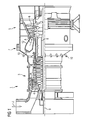
- FIG. 1 shows a gas turbine plant 1 in a partially sectioned side view. This comprises a compressor section 3, a turbine section 5 and a burner section 7. In the compressor section 3 and in the turbine section 5, compressor blades 4 or turbine blades 6 are arranged on a common shaft 8, which is also called turbine rotor.
- the turbine rotor 8 is rotatably mounted about a central axis 9.
- the burner section 7 comprises a number of burners 10, which open into a combustion chamber 12, which in turn opens into the turbine section 5.
- the combustion chamber 12 is formed in the present embodiment as an annular combustion chamber, i. it extends annularly around the turbine rotor 8 around.
- ambient air U is sucked in via the compressor, compressed to a higher pressure and discharged into the burner section 7 as so-called compressor air.
- the magnitude of the air mass flow entering the compressor may be influenced by adjusting the usable compressor inflow cross-section via the first vane ring 32.
- the compressor air enters the burner 10 and is mixed with a fuel supplied to the burner 10 via fuel lines 40 a, 40 b and burned in the combustion chamber 12.
- the size of the supplied fuel mass flows can be influenced via one or more adjustment valves 31a, 31b.
- the combustion exhaust gases produced during combustion form a working medium A, which is fed to the turbine section 5 and there transfers momentum to the moving blades 6 with relaxation and cooling and thus sets the rotor 8 in rotation.
- the rotating rotor 8 on the one hand, drives the compressor and, on the other hand, is coupled to a load (not shown), for example an electric generator for generating electricity.
- the gas turbine plant 1 is equipped with a control device for regulating the driving line by influencing the fuel and / or air supply.
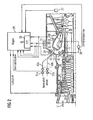
- This device is in the form of a block diagram in FIG FIG. 2 shown.
- the control device comprises a number of sensors 21, 23, 25, 27, 35, 37 which are arranged at different locations inside and outside the gas turbine combustor 12.
- the control device further comprises a controller 29 to which the sensors 21, 23, 25, 27, 35, 37 are connected.
- adjusting means namely the adjusting valves 31 and the vane ring 32, are provided, which are also in communication with the controller 29 and which are adapted to adjust the mass flows of the fuel supply and the air supply to the burner 10.
- one of the fuel mass flows is a so-called diffusion gas mass flow for operating the burner in the diffusion mode in which the gas is injected directly into the flame located in the combustion chamber 12 without first being mixed with air.
- a second fuel mass flow is a so-called Premix gas mass flow for operating the burner in a premix mode, ie a mode in which the supplied gas is previously mixed with the compressor air and this mixture is then burned.
- a pilot gas mass flow is present, which serves, inter alia, to support the flame when the burner is operated in Vormisch memori.
- the sensor 21 is a pressure sensor arranged in the combustion chamber plenum 11 for detecting the alternating pressure in the burner plenum 11, the sensor 25 a pressure sensor arranged on the gas turbine housing for detecting the alternating pressure on the flange 13 of the burner 10 and the sensor 23 an acceleration sensor for detecting the combustion chamber acceleration. This is arranged directly on the outside of the combustion chamber wall.
- the pressure sensors 21 and 25 and the acceleration sensor 23 are therefore connected to the output of their measurement signals with a Fourier transform unit 33 and / or arithmetic unit for determining an averaged autocorrelation (not shown) of the controller 29, in which an analysis of the measurement signals based on a Fourier transform and in particular using a so-called fast Fourier transformation is performed.
- they are also connected directly to the controller 29, ie bypassing the Fourier transformation unit 33, in order to provide the controller 29 with the absolute values of the measurement signals to be able to.
- the oscillating analog signals for several frequency bands are first filtered with exact amplitude and then converted analog-to-digital or they are first converted to analog-digital and then filtered with exact amplitude.
- the autocorrelations are calculated separately for frequency bands at short time intervals based on 2-8 periods of the signal at the respective mean frequency of these frequency bands. Subsequently, the autocorrelations are averaged separately into frequency bands each along with a number of 10-100 contiguous autocorrelations from earlier time steps for the respective frequency bands. Simultaneously with the averaging of the autocorrelations for the respective frequency bands, their variances are determined.
- transients are now formed for the individual frequencies or specific frequency bands. This can be done for example by means of a linear regression calculation. If individual transients or parameters formed with them exceed a certain value, a control intervention takes place, for example reduction of the power or change of the pilot gas quantity. If characteristic values which are formed from the absolute values of the averaged autocorrelations and their transients and, if appropriate, additionally from the variances and transients of the variances of the autocorrelations, exceed specific values, a control intervention takes place, for example, a reduction in the power or change in the pilot gas quantity. By evaluating transients, significantly longer forewarning times can be achieved.
- the controller 29 can determine an approximation to the hum limits of the gas turbine plant 1, in which, for example, stationary oscillations in the combustion gases occur.
- the frequency of vibrations in the combustion exhaust gas are determined after an analysis by the Fourier transformation unit 33.
- the alternating pressure at the burner flange 13 is therefore suitable as an early indicator for approaching the hum limits and as a controlled variable for the regulator for controlling the air and / or fuel supply such that the flame stability is maintained.
- the combustion chamber acceleration responds later than the alternating pressure at the burner flange 13 to an approach to the hum limits. It is therefore particularly suitable for protecting the gas turbine combustor 12 from damage if the regulation of the air and / or fuel supply does not lead to a sufficient stabilization of the flame.
- the combustion chamber acceleration is an indicator of the occurrence of damage to ceramic heat shield elements with which the combustion chamber 12 is lined to protect its supporting structure from the hot combustion exhaust gases. High combustion chamber accelerations can lead to cracks and even breaks in heat shield elements, as a result of which they no longer sufficiently fulfill their protective function. In addition, due to fractures fragments from the heat shield can solve and get into the turbine section, resulting in very serious damage to the turbine. On the basis of the combustion chamber acceleration, therefore, for example, an emergency shutdown of the gas turbine plant can be made if the determined combustion chamber accelerations indicate that cracks or breaks in the heat shield elements threaten.
- the pressure drop also called pressure gradient
- the pressure drop across the combustion chamber 12 decreases immediately before the hum, which is a threatening retreat of the flame in the Burner 10 and thus indicates a flame instability.
- a suitable sensor arrangement for detecting the pressure gradient it is therefore possible to detect a near hum event.
- the pressure drop across the combustion chamber 12 by means of a so-called. Ap measurement.
- the ⁇ p measurement is carried out by means of two pressure sensors 35, 37, one of which is arranged in the combustion chamber plenum 11 and the other 37 in the combustion chamber 12.
- a subtractor 39 connected to the two pressure sensors 35, 37 and the controller 29 forms the difference ⁇ p of the detected pressures, and forwards them to the controller 29, bypassing the Fourier transformation unit 33.
- the controller 29 reacts primarily to changes over time of the measured variables detected by the sensors 21, 23, 25 and less to their absolute values. If, after analyzing the signals arriving from the sensors 21, 23, 25, the controller 29 now detects the approach to a hum limit, it issues an actuating signal to the control valves 31a, 31b, ... and / or to the compressor vane ring 32, which causes a change of at least one fuel mass flow and / or the air mass flow. In particular, it outputs in this case at least one actuating signal to the fuel valve in the feed line of the pilot fuel, in order to optimize the driving line of the gas turbine plant again via a change in the pilot fuel mass flow, i. to lead away from the hum limits. In this case, the corrected exhaust-gas temperature of the gas turbine plant and its power can be adjusted by influencing the main fuel mass flow and / or the air mass flow in such a way that the pollutant emissions are kept at their optimum values or set back to these.
- control valves 31 a, 31 b, ... or the vane ring 32 only on the Fuel mass flow and / or act on the air mass flow to keep on influencing the pilot gas mass flow and / or the gas turbine power and / or the corrected exhaust gas temperature, for example, the emission in the intended range, if he eg. Due to fluctuating factors, such as a fluctuating ambient temperature varies without optimizing the driving line of the gas turbine plant.
- the pilot gas mass flow can be reduced if the nitrogen oxide levels in the exhaust stream are high or are increased when the carbon monoxide levels in the exhaust gas are high.
- the pollutant values in the exhaust gas are detected by means of an emission measuring device 27, which is arranged in the exhaust duct of the combustion chamber system and communicates with the controller 29, bypassing the Fourier transformation unit 33.
- the controller 29 operates on the basis of a fuzzy logic to allow the most gradual possible reaction.
- it can also work with a fixed control law, which is present, for example, as a functional relationship of the actuating signal to be output and the incoming measuring signals or in the form of a table relating the incoming measuring signals to an outgoing actuating signal.
- a controller based on a neural network which enables the controller to learn from previous control events.
Description
Die vorliegende Erfindung betrifft ein Regelverfahren sowie eine Regelvorrichtung zum Regeln der Fahrlinie einer Gasturbinenbrennkammer.The present invention relates to a control method and a control device for controlling the driving line of a gas turbine combustor.
Eine Gasturbine ist eine Strömungsmaschine, die in der Regel einen Verdichter, eine Turbine und einen Brennkammerabschnitt umfasst. Im Verdichter wird angesaugte Umgebungsluft verdichtet und die verdichtete Luft schließlich dem Brennkammerabschnitt zugeführt. Im Brennkammerabschnitt ist wenigstens eine Brennkammer mit zumeist mehreren Brennern angeordnet, denen die verdichtete Luft zugeführt wird. Neben der verdichteten Luft wird den Brennern außerdem ein Brennstoff zugeführt, der mit der Luft vermischt und verbrannt wird. Die dabei in der Brennkammer entstehenden heißen Verbrennungsabgase werden der Turbine zugeführt, wo sie entspannen und abkühlen und dabei die Turbine in Rotation versetzen. Auf diese Weise wird thermische Energie der Verbrennungsabgase in mechanische Arbeit umgewandelt, die einerseits zum Antreiben des Verdichters und andererseits zum Antreiben eines Verbrauchers, beispielsweise eines Generators zum Erzeugen von Strom eingesetzt wird.A gas turbine is a turbomachine that typically includes a compressor, a turbine, and a combustor section. In the compressor sucked ambient air is compressed and the compressed air finally fed to the combustion chamber section. In the combustion chamber section at least one combustion chamber is arranged with mostly a plurality of burners to which the compressed air is supplied. In addition to the compressed air, the burners are also supplied with a fuel that is mixed with the air and burned. The resulting in the combustion chamber hot combustion exhaust gases are supplied to the turbine, where they relax and cool and thereby set the turbine in rotation. In this way, thermal energy of the combustion exhaust gases is converted into mechanical work, which is used on the one hand for driving the compressor and on the other hand for driving a consumer, for example a generator for generating electricity.
Bei der Verbrennung in der Brennkammer ist darauf zu achten, dass eine stabile Flamme vorliegt. Instabilitäten der Flamme treten insbesondere aufgrund von resonanten Verbrennungsschwingungen im Verbrennungsabgas auf und können einerseits zu einem erhöhten Schadstoffausstoß führen und andererseits Schwingungen und Vibrationen der Brennkammer verursachen, welche die Lebensdauer der Brennkammer herabsetzen und Wartungsintervalle verkürzen.When burning in the combustion chamber, make sure that there is a stable flame. Instabilities of the flame occur in particular due to resonant combustion oscillations in the combustion exhaust gas and can both lead to increased pollutant emissions and on the other hand cause vibrations and vibrations of the combustion chamber, which reduce the life of the combustion chamber and shorten maintenance intervals.
Außerdem sind die Brenner üblicherweise außer mit einer Hauptbrennstoffzufuhr auch mit einer sog.In addition, the burners are usually except with a main fuel supply with a so-called.
Pilotbrennstoffzufuhr ausgestattet. Über die Pilotbrennstoffzufuhr wird ein im Vergleich zum Hauptbrennstoffmassenstrom geringer Brennstoffmassenstrom zugeführt, um die die Flamme zu stützen. Zudem kann die Flamme durch Beeinflussen des Massenstroms an zugeführtem Pilotbrennstoff bei Bedarf stabilisiert werden.Pilot fuel supply equipped. The pilot fuel supply supplies a low fuel mass flow compared to the main fuel mass flow to support the flame. In addition, the flame can be stabilized by influencing the mass flow of supplied pilot fuel if necessary.
Die Stabilität der Flamme wird von einer großen Anzahl von Störgrößen beeinflusst. Beispiele für derartige Störgrößen sind die Umgebungstemperatur, die Dichte und der Heizwert des Brennstoffes, aber auch der Bauzustand der Gasturbinenanlage, insbesondere der Brennkammer und der Brenner. Der Einfluss der Störgrößen wird mittels des über den Pilotbrenner zugeführten Brennstoffmassenstroms ausgeglichen. Der Pilotgasmassenstrom darf dabei bestimmte Grenzen nicht unter- bzw. überschreiten, da die Flamme sonst in einen instabilen Bereich überführt werden würde. Um den Pilotgasmassenstrom im stabilen Bereich der Flamme zu halten, findet eine Funktion Anwendung, welche den einzusetzenden Pilotgasmassenstrom in Abhängigkeit von den Störgrößen definiert. Diese Funktion wird auch Pilotgaskurve genannt.The stability of the flame is influenced by a large number of disturbances. Examples of such disturbance variables are the ambient temperature, the density and the calorific value of the fuel, but also the state of construction of the gas turbine plant, in particular the combustion chamber and the burner. The influence of the disturbances is compensated for by means of the fuel mass flow supplied via the pilot burner. The pilot gas mass flow must not fall below or exceed certain limits, as otherwise the flame would be transferred to an unstable region. In order to keep the pilot gas mass flow in the stable region of the flame, a function is used, which defines the pilot gas mass flow to be used as a function of the disturbance variables. This function is also called Pilot Gaskurve.
In die Pilotgaskurve geht eine Anzahl an Gasturbinenparametern ein. Diese Parameter variieren von Gasturbinenanlage zu Gasturbinenanlage, selbst dann, wenn diese baugleich sind. Insbesondere sind auch die Umgebungsbedingungen am Aufstellungsort der Gasturbinenanlage zu berücksichtigen. Zudem können die Gasturbinenparameter beim Betrieb einer Gasturbinenanlage mit der Zeit Veränderungen unterworfen sein. Dies führt dazu, dass ein zeitaufwendiges Neueinstellen oder Nacheinstellen der Pilotgaskurve nötig werden kann. Durch den Einstellungsprozess werden hohe Kosten und Stillstandzeiten verursacht.A number of gas turbine parameters are included in the pilot gas curve. These parameters vary from gas turbine plant to gas turbine plant, even if they are identical in construction. In particular, the environmental conditions at the site of the gas turbine plant are taken into account. In addition, the gas turbine parameters during operation of a gas turbine plant may be subject to changes over time. This leads to the need for a time-consuming readjustment or readjustment of the pilot gas curve. The hiring process causes high costs and downtime.
Hinzukommt noch, dass der Einfluss der Störgrößen auf die Pilotgaskurve quantitativ nur unzureichend bekannt ist. Auf manche Störgrößen kann überhaupt nicht adäquat reagiert werden.In addition, the influence of the disturbances on the pilot gas curve is insufficiently known quantitatively. On some disturbances can not be adequately responded at all.
Die
Die
Die
Aufgabe der vorliegenden Erfindung ist es daher, ein Regelverfahren und eine Regelvorrichtung zur Verfügung zu stellen, das bzw. die sich vorteilhaft zum Unterbinden von Flammeninstabilitäten einsetzen lässt.The object of the present invention is therefore to provide a control method and a control device which can be advantageously used to prevent flame instabilities.
Diese Aufgabe wird durch ein Regelverfahren nach Anspruch 1 bzw. eine Regelvorrichtung nach Anspruch 13 gelöst. Die abhängigen Ansprüche enthalten vorteilhafte Ausgestaltungen der Erfindung.This object is achieved by a control method according to claim 1 and a control device according to
Im erfindungsgemäßen Regelverfahren zum Regeln der Fahrlinie einer Gasturbinenanlage wird wenigstens eine Regelgröße erfasst, die erfasste Regelgröße mit einer vorgegebenen Führungsgröße verglichen, auf der Basis des Vergleichs wenigstens eine Stellgröße ermittelt. Die ermittelte Stellgröße wird an wenigstens eine die Luft- und/oder Brennstoffzufuhr zu einer Brennkammer der Gasturbinenanlage beeinflussende Stelleinrichtung ausgegeben. Als wenigstens eine Regelgröße dient hierbei eine Regelgröße, aus welcher sich die Annäherung der Flamme an eine Stabilitätsgrenze ableiten lässt. Als derartige Regelgrößen kommen insbesondere zeitliche Änderungen wenigstens eines Brennerparameters oder eines Brennkammerparameters in Betracht. Insbesondere können als Brennkammerparameter ein Wechseldruck in der Brennkammer und/oder eine Brennkammerbeschleunigung herangezogen werden. Als Brennerparameter oder Brennkammerparameter wird mindestens die zeitliche Änderung eines Wechseldruckes an einem Brennerflansch erfasst und/oder die zeitliche Änderung eines Wechseldruckes in einem Brennerplenum. Der Wechseldruck im Brennerplenum wird mittels eines im Brennerplenum angeordneten Sensors erfasst.In the control method according to the invention for regulating the driving line of a gas turbine plant, at least one controlled variable is detected, the detected controlled variable compared with a predetermined reference variable, and based on the comparison, at least one manipulated variable is determined. The determined manipulated variable is output to at least one adjusting device influencing the air and / or fuel supply to a combustion chamber of the gas turbine plant. At least one controlled variable serves as a controlled variable from which the approach of the flame to a stability limit can be derived. In particular, temporal changes of at least one burner parameter or one combustion chamber parameter come into consideration as such controlled variables. In particular, an alternating pressure in the combustion chamber and / or a combustion chamber acceleration can be used as the combustion chamber parameters. As a burner parameter or combustion chamber parameters, at least the temporal change of an alternating pressure at a burner flange is detected and / or the time change of an alternating pressure in a burner plenum. The alternating pressure in the burner plenum is detected by means of a sensor arranged in the burner plenum.
Mit dem erfindungsgemäßen Regelverfahren lässt sich die Flamme stabil halten, ohne dass der Einfluss der Störgrößen auf die Flammenstabilität quantitativ genau bekannt sein muss.With the control method according to the invention, the flame can be kept stable without the influence of the disturbances on the flame stability must be known exactly quantitatively.
Die Erfindung beruht auf dem folgenden neuen Konzept. Statt wie im Stand der Technik auf die Störgrößen zu schauen, um die Stabilität der Flamme aufrecht zu erhalten, wird in dem erfindungsgemäßen Regelungsverfahren auf die Brummgrenzen, d.h. die Stabilitätsgrenzen selbst geschaut. Mit anderen Worten, der Pilotgasmassenstrom wird nicht in Abhängigkeit von den detektierten Störgrößen variiert sondern bei Annäherung an eine Brummgrenze geändert. Das Feststellen der Annäherung an eine Brummgrenze erfolgt dabei ohne quantitative Kenntnis der Störgrößen.The invention is based on the following new concept. Instead of looking at the disturbance variables as in the prior art in order to maintain the stability of the flame, in the control method according to the invention, the marginal boundaries, ie the stability limits themselves, are observed. In other words, the pilot gas mass flow is not varied as a function of the detected disturbance variables but changed when approaching a hum limit. The determination of the approach to a hum limit takes place without quantitative knowledge of the disturbances.
Erfindungsgemäß ist die quantitative Kenntnis der Störgrößen nicht notwendig, um die Brummgrenzen, die sich mit den Störgrößen verschieben, zu ermitteln und so eine Pilotgaskurve zur Verfügung stellen zu können, die sich für alle Störgrößen innerhalb der Brummgrenzen bewegt. Da wie bereits in der Einleitung ausgeführt der Einfluss der Störgrößen auf die Brummgrenzen selbst bei baugleichen Gasturbinenanlagen beispielsweise aufgrund unterschiedlicher Umgebungsbedingungen variiert, ist erfindungsgemäß ein individuelles Einstellen jeder Gasturbinenanlage nicht nötig.According to the invention, the quantitative knowledge of the disturbance variables is not necessary in order to be able to determine the buzz boundaries which shift with the disturbance variables and thus to be able to provide a pilot gas curve which moves for all disturbances within the buzz boundaries. Since, as already stated in the introduction, the influence of the disturbance variables on the humbeam boundaries varies even with structurally identical gas turbine systems, for example due to different ambient conditions, an individual adjustment of each gas turbine plant is not necessary according to the invention.
Im erfindungsgemäßen Verfahren ist eine quantitative Kenntnis der Beziehung zwischen den Störgrößen und der Lage der Brummgrenzen nicht notwendig, da die Variation der Pilotgasmenge zum Stabilisieren der Flamme direkt davon abhängig gemacht werden kann, ob eine Annäherung an eine Brummgrenze erfolgt oder nicht und eine direkte Detektion einer Annäherung an die Brummgrenzen erfolgt. Daneben wird das Pilotgas auch weiterhin zum Stützen der Flamme herangezogen.In the method according to the invention, a quantitative knowledge of the relationship between the disturbance variables and the position of the brim boundaries is not necessary, since the variation of the pilot gas quantity for stabilizing the flame can be made directly dependent on whether or not an approach to a hum limit occurs and a direct detection of a Approaching the hum limits occurs. In addition, the pilot gas will continue to be used to support the flame.
Zum Feststellen der Annäherung an eine Brummgrenze kann die zeitliche Änderung der bereits erwähnten Brennerparameter bzw. Brennkammerparameter herangezogen werden. Besonders geeignet ist hierbei der Wechseldruck an einem Brennerflansch, da dieser früher auf eine Annäherung an eine Brummgrenze reagiert, als der Wechseldruck in der Brennkammer und die Brennkammerbeschleunigung. Grundsätzlich sind jedoch alle der genannten Brennkammerparameter zum Feststellen einer Annäherung an die Brummgrenze geeignet.To determine the approach to a hum limit, the time change of the already mentioned burner parameters or combustion chamber parameters can be used. Particularly suitable in this case is the alternating pressure at a burner flange, since it reacts earlier to an approach to a hum limit than the alternating pressure in the combustion chamber and the combustion chamber acceleration. Basically, however all of the said combustion chamber parameters are suitable for determining an approach to the hum limit.
Die genannten Brennerparameter und Brennkammerparameter (zum Beispiel der Wechseldruck, Brennkammerbeschleunigung oder OH-Strahlung) stellen oszillierende Größen dar, die zum Bewerten der Annäherung an eine Flammeninstabilität einer schnellen Fouriertransformation FFT (Fast Fourier Transformation) und/oder gemittelten Autokorrelationen unterzogen werden. Die schnelle Fouriertransformation und oder gemittelten Autokorrelationen stellen ein besonders geeignetes Mittel zum Analysieren zeitlich veränderlicher Größen dar.The aforementioned burner parameters and combustion chamber parameters (for example the alternating pressure, combustion chamber acceleration or OH radiation) represent oscillating quantities which are subjected to fast Fourier transformation FFT (Fast Fourier Transformation) and / or averaged autocorrelations in order to assess the approach to flame instability. The fast Fourier transform and or averaged autocorrelations are a particularly suitable means of analyzing variables that vary with time.
Für die Bestimmung der Autokorrelationen werden die oszillierenden analogen Signale für mehrere Frequenzbänder zunächst amplitudengenau gefiltert und anschließend analog-digital gewandelt oder sie werden zunächst analog-digital gewandelt und anschließend amplitudengenau gefiltert. Die Autokorrelationen werden getrennt nach Frequenzbänder in kurzen zeitlichen Abständen auf der Grundlage von 2-8 Periodendauern des Signals bei der jeweiligen mittleren Frequenz dieser Frequenzbänder berechnet. Anschließend werden die Autokorrelationen getrennt nach Frequenzbänder jeweils zusammen mit einer Anzahl von 10-100 angrenzenden, aufeinander folgenden Autokorrelationen aus früheren Zeitschritten für die jeweiligen Frequenzbänder, gemittelt. Gleichzeitig mit der Mittelung der Autokorrelationen für die jeweiligen Frequenzbänder werden ihre Varianzen bestimmt.For the determination of the autocorrelations, the oscillating analog signals for several frequency bands are first filtered with exact amplitude and then converted analog-to-digital or they are first converted to analog-digital and then filtered with exact amplitude. The autocorrelations are calculated separately for frequency bands at short time intervals based on 2-8 periods of the signal at the respective mean frequency of these frequency bands. Subsequently, the autocorrelations are averaged separately into frequency bands each along with a number of 10-100 contiguous autocorrelations from earlier time steps for the respective frequency bands. Simultaneously with the averaging of the autocorrelations for the respective frequency bands, their variances are determined.
Aus diesen Frequenzspektren und/oder gemittelten Autokorrelationen und/oder Varianzen der Autokorrelationen werden jetzt für die einzelnen Frequenzen oder bestimmte Frequenzbänder Transienten gebildet. Dies kann beispielsweise mit Hilfe einer linearen Regressionsrechnung erfolgen. Überschreiten einzelne Transienten oder damit gebildete Kenngrößen einen bestimmten Wert so erfolgt ein Regeleingriff, z.B. Reduzierung der Leistung oder Veränderung der Pilotgasmenge.From these frequency spectra and / or averaged autocorrelations and / or variances of the autocorrelations, transients are now formed for the individual frequencies or specific frequency bands. This can be done for example by means of a linear regression calculation. If individual transients or parameters formed with them exceed a certain value, a control intervention takes place, for example reduction of the power or change of the pilot gas quantity.
Überschreiten Kenngrößen, die aus den Absolutwerten der gemittelten Autokorrelationen sowie ihren Transienten sowie gegebenenfalls zusätzlich aus den Varianzen und den Transienten der Varianzen der Autokorrelation gebildet werden, bestimmte Werte, so erfolgt ein Regeleingriff zum Beispiel eine Reduzierung der Leistung oder Veränderung der Pilotgasmenge. Durch die Auswertung von Transienten lassen sich deutlich größere Vorwarnzeiten erzielen.If characteristic values which are formed from the absolute values of the averaged autocorrelations and their transients and, if appropriate, additionally from the variances and the transients of the variances of the autocorrelation exceed specific values, a control intervention takes place, for example, a reduction in the power or change in the pilot gas quantity. By evaluating transients, significantly longer forewarning times can be achieved.
Weiterhin können im Regelverfahren neben dem wenigstens einen Brennerparameter und/oder dem wenigstens einen Brennkammerparameter ein oder mehrere Verbrennungsparameter als Regelgrößen erfasst werden. Ein geeigneter Verbrennungsparameter ist beispielsweise der Schadstoffausstoß der Gasturbinenanlage, insbesondere der Stickoxidgehalt (NOx-Gehalt) und/oder der Kohlenmonoxidgehalt (CO-Gehalt) im Verbrennungsabgas. Ein ebenfalls geeigneter Verbrennungsparameter ist der Druckabfall über die Brennkammer.Furthermore, one or more combustion parameters can be detected as controlled variables in the control method in addition to the at least one burner parameter and / or the at least one combustion chamber parameter. A suitable combustion parameter is, for example, the pollutant emissions of the gas turbine plant, in particular the nitrogen oxide content (NO x content) and / or the carbon monoxide content (CO content) in the combustion exhaust gas. Another suitable combustion parameter is the pressure drop across the combustion chamber.
Zudem können im erfindungsgemäßen Regelverfahren die Absolutwerte der Brennerparameter und der Brennkammerparameter zur weiteren Unterstützung erfasst werden. In erster Linie wird jedoch auf die zeitliche Änderung der Brennerparameter und der Brennkammerparameter geachtet, um eine Annäherung an die Brummgrenzen festzustellen.In addition, in the control method according to the invention, the absolute values of the burner parameters and the combustion chamber parameters can be detected for further assistance. Primarily, however, attention is paid to the temporal change of the burner parameters and the combustion chamber parameters in order to determine an approximation to the hum limits.
Als Stellgröße kann wenigstens eine Größe ausgegeben werden, welche zu einer Änderung der Gasturbinenleistung führt, und/oder eine Größe, welche eine Änderung der korrigierten Abgastemperatur der Verbrennungsabgase führt. Insbesondere wird jedoch eine Größe als Stellgröße ausgegeben, welche eine Änderung des Pilotgasmassenstroms repräsentiert. Eine Änderung der Gasturbinenleistung oder der korrigierten Abgastemperatur erfolgt in der Regel indirekt über eine Änderung der Absolutwerte der Luft- und Hauptbrennstoffzufuhr sowie über eine Änderung des Verhältnisses von Luftzufuhr zu Hauptbrennstoffzufuhr. Als Größen, die zu einer Änderung der Gasturbinenleistung oder der korrigierten Abgastemperatur führen, sind daher insbesondere solche Größen anzusehen, welche einzustellende Absolutwerte der Luftzufuhr und/oder der Hauptbrennstoffzufuhr und/oder des Verhältnisses von Luftzufuhr zu Hauptbrennstoffzufuhr repräsentieren. Änderungen der Gasturbinenleistung können bspw. dazu eingesetzt werden, die Gasturbinenanlage im Emissionsbereich zu halten, ohne die eigentliche Fahrlinie der Anlage zu verlassen. Die Änderung des Pilotgasmassenstroms wird hingegen eingesetzt, wenn die Fahrlinie der Gasturbinenanlage verändert werden soll, um das Erreichen der Brummgrenzen zu verhindern. Gegebenenfalls kann dies mit einer Änderung der korrigierten Abgastemperatur und/oder der Gasturbinenleistung kombiniert werden.As a manipulated variable at least one size can be output, which leads to a change in the gas turbine power, and / or a size, which leads to a change in the corrected exhaust gas temperature of the combustion exhaust gases. In particular, however, a variable is output as a manipulated variable, which represents a change in the pilot gas mass flow. A change in the gas turbine power or the corrected exhaust gas temperature is usually carried out indirectly via a change in the absolute values of the air and main fuel supply and a change in the ratio of air intake to main fuel supply. As variables that lead to a change in the gas turbine power or the corrected exhaust gas temperature, therefore, in particular those quantities are to be considered, which represent absolute values to be set of the air supply and / or the main fuel supply and / or the ratio of air supply to main fuel supply. Changes in the gas turbine power can be used, for example, to keep the gas turbine plant in the emission range, without leaving the actual driving line of the system. The change in the pilot gas mass flow, however, is used when the driving line of the gas turbine plant is to be changed in order to prevent reaching the hum limits. Optionally, this may be combined with a change in the corrected exhaust gas temperature and / or the gas turbine power.
Die Verknüpfung zwischen der erfassten Regelgröße und der Führungsgröße einerseits mit der Stellgröße andererseits kann insbesondere auf der Basis einer Fuzzy-Logic erfolgen. Alternativ ist es jedoch auch möglich ein, neuronales Netzwerk oder ein festes Regelgesetz zu verwenden. Die Fuzzy-Logic ermöglicht es insbesondere, Abstufungen in der Reaktion in Abhängigkeit vom Grad der Annäherung an die Brummgrenzen zu realisieren.The link between the detected controlled variable and the reference variable on the one hand with the manipulated variable on the other hand can be done in particular on the basis of a fuzzy logic. Alternatively, however, it is also possible to use a neural network or a fixed control law. In particular, the fuzzy logic makes it possible to realize gradations in the response as a function of the degree of approach to the hum limits.
Insgesamt ermöglicht das erfindungsgemäße Regelverfahren das Erreichen und Überschreiten der Brummgrenzen zuverlässig zu verhindern. Schnellschlüsse der Gasturbinenanlage, d.h. Schnellabschaltungen der Anlage, aufgrund des Erreichens der Brummgrenzen können so zuverlässig vermieden werden. Außerdem können die Betriebsgrenzen der Gasturbinenanlage besser ausgenutzt werden. Beispielsweise kann ein hoher Stickoxidausstoß aufgrund einer erhöhten Flammeninstabilität vermindert werden, oder es kann eine höhere korrigierte Abgastemperatur (OTC Outlet Temperature Corrected) zur Anwendung kommen, wodurch sich der Wirkungsgrad der Gasturbinenanlage verbessern lässt. Ebenso ist es möglich, eine Absenkung der korrigierten Abgastemperatur bei Unterschreiten einer bestimmten Verdichtereintrittstemperatur zu vermeiden oder wenigstens zu verringern. Unter der Verdichtereintrittstemperatur ist hierbei die Temperatur der vom Verdichter angesaugten Luft beim Eintritt in den Verdichter zu verstehen.Overall, the control method according to the invention makes it possible to reliably prevent the reaching and exceeding of the hum limits. Quick shutdown of the gas turbine plant, ie rapid shutdown of the system, due to reaching the hum limits can be reliably avoided. In addition, the operating limits of the gas turbine plant can be better utilized. For example, high nitrogen oxide emissions may be reduced due to increased flame instability, or a higher OTC Outlet Temperature Corrected temperature may be used, thereby increasing the efficiency of the process Gas turbine plant can be improved. Likewise, it is possible to avoid or at least reduce a reduction in the corrected exhaust gas temperature when falling below a certain compressor inlet temperature. Under the compressor inlet temperature here is the temperature of the intake air from the compressor to be understood when entering the compressor.
Eine erfindungsgemäße Regelvorrichtung zum Regeln der Fahrlinie einer Gasturbinenanlage umfasst:
- Wenigstens einen Sensor zum Erfassen einer Messgröße und zum Ausgeben eines die Messgröße repräsentierenden Messsignals.
- Wenigsten eine Stelleinrichtung zum Beeinflussen der Luftzufuhr und/oder der Brennstoffzufuhr zu einer Brennkammer der Gasturbinenanlage auf der Basis einer Stellgröße.
- Einen mit dem wenigstens einen Sensor zum Empfang der Messgröße und der wenigstens einen Stelleinrichtung zum Ausgeben der Stellgröße verbundenen Regler.
- At least one sensor for detecting a measured variable and for outputting a measuring signal representing the measured variable.
- At least one adjusting device for influencing the air supply and / or the fuel supply to a combustion chamber of the gas turbine plant on the basis of a manipulated variable.
- One connected to the at least one sensor for receiving the measured variable and the at least one adjusting device for outputting the manipulated variable controller.
Der Regler ist zum Ermitteln der Stellgröße auf der Basis der empfangenen Messgröße und deren Abweichung von einer Führungsgröße ausgelegt. In der erfindungsgemäßen Regelvorrichtung ist wenigstens ein Sensor vorhanden, der dazu ausgestaltet ist, die zeitliche Änderung eines Brennerparameters oder eines Brennerkammerparameters zu erfassen. In der erfindungsgemäßen Regelvorrichtung ist wenigstens ein Sensor vorhanden, der dazu ausgestaltet ist, die zeitliche Änderung wenigstens eines Wechseldruckes an einem Brennerflansch zu erfassen und/oder es ist wenigstens ein Sensor vorhanden, der dazu ausgestaltet ist, die zeitliche Änderung eines Wechseldruckes in einem Brennerplenum zu erfassen. Der Sensor zur Erfassung des Wechseldruckes in einem Brennerplenum ist in dem Brennerplenum angeordnet.The controller is designed to determine the manipulated variable on the basis of the received measured variable and its deviation from a reference variable. In the control device according to the invention at least one sensor is provided, which is designed to detect the temporal change of a burner parameter or a burner chamber parameter. In the control device according to the invention at least one sensor is provided, which is designed to detect the time change of at least one alternating pressure on a burner flange and / or there is at least one sensor which is adapted to the temporal change of an alternating pressure in a Brennerplenum to capture. The sensor for detecting the alternating pressure in a burner plenum is arranged in the burner plenum.
Mit der erfindungsgemäßen Regelvorrichtung kann das erfindungsgemäße Verfahren durchgeführt werden, wodurch sich die Fahrlinie der Gasturbinenanlage insbesondere durch verbessertes Vermeiden von Flammeninstabilitäten optimieren lässt.With the control device according to the invention, the inventive method can be carried out, whereby the driving line of the gas turbine plant can be optimized in particular by improved prevention of flame instabilities.
Weiterhin kann als Sensor hierbei insbesondere ein Sensor zum Erfassen eines Wechseldruckes in der Brennkammer und/oder ein Sensor zum Erfassen einer Brennkammerbeschleunigung vorhanden sein. Daneben kann wenigstens ein mit dem Regler verbundener Sensor zum Erfassen eines Verbrennungsparameters, beispielsweise eine Emissionsmessvorrichtung, mit der sich bspw. der Stickoxidgehalt oder der Kohlenmonoxidgehalt des Verbrennungsabgases ermitteln lässt, oder ein Sensor zum Erfassen eines absoluten Wertes eines Brenner- oder Brennkammerparameters vorhanden sein.Furthermore, a sensor for detecting an alternating pressure in the combustion chamber and / or a sensor for detecting a combustion chamber acceleration may be present as a sensor here. In addition, at least one sensor connected to the controller for detecting a combustion parameter, for example an emission measuring device with which, for example, the nitrogen oxide content or the carbon monoxide content of the combustion exhaust gas can be determined, or a sensor for detecting an absolute value of a burner or combustion chamber parameter can be present.
Als Stelleinrichtung kann wenigstens ein Brennstoffventil zum Beeinflussen eines in die Brennkammer eingeleiteten Brennstoffmassenstroms dienen. Vorzugsweise sind wenigstens ein Brennstoffventil für eine Hauptbrennstoffleitung und eines für die Pilotbrennstoffleitung vorhanden.At least one fuel valve for influencing a fuel mass flow introduced into the combustion chamber can serve as setting device. Preferably, at least one fuel valve is provided for a main fuel line and one for the pilot fuel line.
Als Stelleinrichtung kann alternativ oder vorzugsweise zusätzlich zu dem wenigstens einen Brennstoffventil der erste Leitschaufelkranz des Verdichters, also der Leitschaufelkranz, welcher der einströmenden Luft einströmseitig zugewandt ist, dienen. Dieser Leitschaufelkranz weist in der Regel bewegliche Leitschaufeln auf, mit denen der zum Einströmen von Luft zur Verfügung stehende Einströmquerschnitt des Verdichters variiert werden kann.As an adjusting device may alternatively or preferably in addition to the at least one fuel valve, the first vane ring of the compressor, so the vane ring, which faces the inflowing air upstream serve. As a rule, this vane ring has movable guide vanes with which the inflow cross section of the compressor available for the inflow of air can be varied.
Wenn ein die zeitliche Änderung eines Brennerparameters oder eines Brennerkammerparameters erfassender Sensor zum Erfassen einer oszillierenden Messgröße ausgebildet ist, kann der Regelvorrichtung eine Fouriertransformationseinheit zugeordnet sein, die zum Durchführen einer schnellen Fouriertransformation ausgebildet ist, und/oder einer Recheneinheit zum Ermitteln gemittelter Autokorrelation um ein geeignetes Mittel zum Analysieren der oszillierenden Messgröße zur Verfügung zu stellen.If a sensor which detects the change over time of a burner parameter or of a burner chamber parameter is designed to detect an oscillating measured variable, the control device can use a Fourier transformation unit be assigned, which is designed to perform a fast Fourier transform, and / or a computing unit for determining averaged autocorrelation to provide a suitable means for analyzing the oscillating measured variable.
Weitere Merkmale, Eigenschaften und Vorteile der vorliegenden Erfindung ergeben sich aus der nachfolgenden Beschreibung eines Ausführungsbeispiels unter Bezugnahme auf die beiliegenden Figuren.
- FIG 1
- zeigt eine Gasturbinenanlage in einer teilweise geschnittenen Seitenansicht.
- FIG 2
- zeigt eine erfindungsgemäße Regelvorrichtung in Form eines Blockdiagrammes.
- FIG. 1
- shows a gas turbine plant in a partially sectioned side view.
- FIG. 2
- shows a control device according to the invention in the form of a block diagram.
Der Brennerabschnitt 7 umfasst eine Anzahl Brenner 10, die in eine Brennkammer 12 münden, welche wiederum in den Turbinenabschnitt 5 mündet. Die Brennkammer 12 ist im vorliegenden Ausführungsbeispiel als Ringbrennkammer ausgebildet, d.h. sie erstreckt sich ringförmig um den Turbinenläufer 8 herum.The
Im Betrieb der Gasturbinenanlage 1 wird über den Verdichter Umgebungsluft U eingesaugt, auf einen höheren Druck verdichtet und in den Brennerabschnitt 7 als sogenannte Verdichterluft ausgegeben. Die Größe des in den Verdichter eintretenden Luftmassenstroms kann durch Einstellen des nutzbaren Verdichtereinströmquerschnittes mittels des ersten Leitschaufelkranzes 32 beeinflusst werden.During operation of the gas turbine plant 1, ambient air U is sucked in via the compressor, compressed to a higher pressure and discharged into the
Im Brennerabschnitt 7 tritt die Verdichterluft in den Brenner 10 ein und wird mit einem dem Brenner 10 über Brennstoffleitungen 40a, 40b zugeführten Brennstoff vermischt und in der Brennkammer 12 verbrannt. Die Größe der zugeführten Brennstoffmassenströme lässt sich hierbei über ein oder mehrere Einstellventile 31a, 31b beeinflussen.In the
Die bei der Verbrennung entstehenden Verbrennungsabgase bilden ein Arbeitsmedium A, welches dem Turbinenabschnitt 5 zugeleitet wird und dort unter Entspannung und Abkühlung Impuls auf die Laufschaufeln 6 überträgt und so den Rotor 8 in Rotation versetzt. Der rotierende Rotor 8 treibt einerseits den Verdichter an und ist andererseits mit einem Verbraucher (nicht dargestellt) gekoppelt, beispielsweise einem elektrischen Generator zum Erzeugen von Strom.The combustion exhaust gases produced during combustion form a working medium A, which is fed to the turbine section 5 and there transfers momentum to the moving
Um Instabilitäten der Flamme in der Brennkammer 12 zu vermeiden, ist die Gasturbinenanlage 1 mit einer Regelvorrichtung zum Regeln der Fahrlinie durch Beeinflussen der Brennstoff- und/oder Luftzufuhr ausgestattet. Diese Vorrichtung ist in Form eines Blockdiagrammes in
In der Gasturbinenanlage 1 sind insbesondere drei einstellbare Brennstoffmassenströme und ein einstellbarer Luftmassenstrom vorhanden. Wenn beispielsweise ein gasförmiger Brennstoff zum Einsatz kommt, so ist einer der Brennstoffmassenströme ein sogenannter Diffusionsgasmassenstrom zum Betreiben des Brenners im Diffusionsmodus, in welchem das Gas direkt in die in der Brennkammer 12 befindliche Flamme eingedüst wird, ohne vorher mit Luft vermischt zu werden. Ein zweiter Brennstoffmassenstrom ist ein sogenannter Vormischgasmassenstrom zum Betreiben des Brenners in einem Vormischmodus, d.h. einem Modus, in welchem das zugeführte Gas zuvor mit der Verdichterluft vermischt wird und dieses Gemisch anschließend verbrannt wird. Schließlich ist als weiterer Brennstoffmassenstrom im vorliegenden Ausführungsbeispiel ein Pilotgasmassenstrom vorhanden, welcher u.a. dazu dient, die Flamme zu stützen, wenn der Brenner im Vormischbetrieb betrieben wird.In the gas turbine plant 1 in particular three adjustable fuel mass flows and an adjustable air mass flow are available. For example, when a gaseous fuel is used, one of the fuel mass flows is a so-called diffusion gas mass flow for operating the burner in the diffusion mode in which the gas is injected directly into the flame located in the
Mit den Sensoren 21, 23, 25, 27, 35, 37 werden verschiedene Brennkammerparameter und Verbrennungsparameter erfasst und an den Regler 29 in Form von die erfasste Messgröße repräsentierenden Signalen weitergegeben.With the
Der Sensor 21 ist ein im Brennkammerplenum 11 angeordneter Drucksensor zum Erfassen des Wechseldruckes im Brennerplenum 11 , der Sensor 25 ein am Gasturbinengehäuse angeordneter Drucksensor zum Erfassen des Wechseldruckes am Flansch 13 der des Brenners 10 und der Sensor 23 ein Beschleunigungssensor zum Erfassen der Brennkammerbeschleunigung. Dieser ist direkt an der Außenseite der Brennkammerwand angeordnet.The
Alle drei erfassten Parameter, nämlich der Wechseldruck im Brennerplenum, der Wechseldruck am Brennerflansch sowie die Brennkammerbeschleunigung sind oszillierende Größen, welche Schwingungen in den Verbrennungsabgasen widerspiegeln. Die Drucksensoren 21 und 25 sowie der Beschleunigungssensor 23 sind daher zur Ausgabe ihrer Messsignale mit einer Fouriertransformationseinheit 33 und/oder Recheneinheit zum Ermitteln einer gemittelten Autokorrelation (nicht gezeigt) des Reglers 29 verbunden, in welcher eine Analyse der Messsignale anhand einer Fouriertransformation und insbesondere anhand einer sog. schnellen Fouriertransformation durchgeführt wird. Daneben sind sie auch direkt mit dem Regler 29, d.h. unter Umgehung der Fouriertransformationseinheit 33, verbunden, um dem Regler 29 auch die Absolutwerte der Messsignale zur Verfügung stellen zu können. Für die Bestimmung der Autokorrelationen werden die oszillierenden analogen Signale für mehrere Frequenzbänder zunächst amplitudengenau gefiltert und anschließend analog-digital gewandelt oder sie werden zunächst analog-digital gewandelt und anschließend amplitudengenau gefiltert. Die Autokorrelationen werden getrennt nach Frequenzbänder in kurzen zeitlichen Abständen auf der Grundlage von 2-8 Periodendauern des Signals bei der jeweiligen mittleren Frequenz dieser Frequenzbänder berechnet. Anschließend werden die Autokorrelationen getrennt nach Frequenzbänder jeweils zusammen mit einer Anzahl von 10-100 angrenzenden, aufeinander folgenden Autokorrelationen aus früheren Zeitschritten für die jeweiligen Frequenzbänder gemittelt. Gleichzeitig mit der Mittelung der Autokorrelationen für die jeweiligen Frequenzbänder werden ihre Varianzen bestimmt. Aus diesen Frequenzspektren und/oder gemittelten Autokorrelationen und/oder Varianzen der Autokorrelation werden jetzt für die einzelnen Frequenzen oder bestimmte Frequenzbänder Transienten gebildet. Dies kann beispielsweise mit Hilfe einer linearen Regressionsrechnung erfolgen. Überschreiten einzelne Transienten oder damit gebildete Kenngrößen einen bestimmten Wert so erfolgt ein Regeleingriff, z.B. Reduzierung der Leistung oder Veränderung der Pilotgasmenge. Überschreiten Kenngrößen, die aus den Absolutwerten der gemittelten Autokorrelationen sowie ihren Transienten sowie gegebenenfalls zusätzlich aus den Varianzen und den Transienten der Varianzen der Autokorrelationen gebildet werden, bestimmte Werte, so erfolgt ein Regeleingriff zum Beispiel eine Reduzierung der Leistung oder Veränderung der Pilotgasmenge. Durch die Auswertung von Transienten lassen sich deutlich größere Vorwarnzeiten erzielen.All three parameters recorded, namely the alternating pressure in the burner plenum, the alternating pressure at the burner flange and the combustion chamber acceleration are oscillating variables which reflect vibrations in the combustion exhaust gases. The
Auf der Basis des Ergebnisses der Fouriertransformation kann der Regler 29 eine Annäherung an die Brummgrenzen der Gasturbinenanlage 1, bei denen bspw. stationäre Schwingungen in den Verbrennungsgasen auftreten, feststellen. Insbesondere kann auf Basis einer Messung des Wechseldruckes am Brennerflansch 13 nach einer Analyse durch die Fouriertransformationseinheit 33 die Frequenz von Schwingungen im Verbrennungsabgas ermittelt werden. Der Wechseldruck am Brennerflansch 13 eignet sich daher als Frühindikator für eine Annäherung an die Brummgrenzen und als Regelgröße für den Regler zum Regeln der Luft- und/oder Brennstoffzufuhr derart, dass die Flammenstabilität erhalten bleibt.On the basis of the result of the Fourier transformation, the
Die Brennkammerbeschleunigung reagiert später als der Wechseldruck am Brennerflansch 13 auf eine Annäherung an die Brummgrenzen. Sie eignet sich daher insbesondere dazu, die Gasturbinenbrennkammer 12 vor Beschädigungen zu schützen, wenn das Regeln der Luft und/oder Brennstoffzufuhr nicht zu einer ausreichenden Stabilisierung der Flamme führt. So ist die Brennkammerbeschleunigung bspw. ein Indikator für das Auftreten von Beschädigungen an keramischen Hitzeschildelementen, mit denen die Brennkammer 12 zum Schutz ihrer tragenden Struktur vor den heißen Verbrennungsabgasen ausgekleidet ist. Hohe Brennkammerbeschleunigungen können zu Rissen und sogar zu Brüchen in Hitzeschildelementen führen, wodurch diese ihre Schutzfunktion nicht mehr ausreichend erfüllen. Zudem können sich infolge von Brüchen Bruchstücke aus dem Hitzeschild lösen und in den Turbinenabschnitt gelangen, was zu sehr gravierenden Beschädigungen der Turbine führt. Auf der Basis der Brennkammerbeschleunigung kann daher bspw. eine Notabschaltung der Gasturbinenanlage vorgenommen werden, wenn die ermittelten Brennkammerbeschleunigungen anzeigen, dass Risse oder Brüche in den Hitzeschildelementen drohen.The combustion chamber acceleration responds later than the alternating pressure at the
Außer den Wechseldrücken in der Brennkammer 12 und am Brennerflansch 13 sowie der Brennkammerbeschleunigung kann auch der Druckabfall, auch Druckgradient genannt, über die Brennkammer 12 zum Feststellen eines bevorstehenden Brummereignisses herangezogen werden. So sinkt der Druckabfall über die Brennkammer 12 unmittelbar vor dem Brummen ab, was ein drohendes zurückziehen der Flamme in den Brenner 10 und damit eine Flammeninstabilität anzeigt. Mittels einer geeigneten Sensoranordnung zum Erfassen des Druckgradienten ist daher das Detektieren eines nahen Brummereignisses möglich.In addition to the alternating pressures in the
Der Druckabfall über die Brennkammer 12 erfolgt mittels einer sog. Δp-Messung. Im vorliegenden Ausführungsbeispiel wird die Δp-Messung mittels zweier Drucksensoren 35, 37 durchgeführt, von denen der eine 35 im Brennkammerplenum 11 und der andere 37 in der Brennkammer 12 angeordnet ist. Ein mit den beiden Drucksensoren 35, 37 sowie dem Regler 29 verbundener Subtrahierer 39 bildet die Differenz Δp der erfassten Drücke, und gibt diese unter Umgehung der Fouriertransformationseinheit 33 an den Regler 29 weiter.The pressure drop across the
Der Regler 29 reagiert in erster Linie auf zeitliche Änderungen der von den Sensoren 21, 23, 25 erfassten Messgrößen und weniger auf ihre absoluten Werte. Wenn der Regler 29 nun nach der Analyse der von den Sensoren 21, 23, 25 eingehenden Signale die Annäherung an eine Brummgrenze feststellt, so gibt er ein Stellsignal an die Stellventile 31a, 31b, ... und/oder an den Verdichterleitschaufelkranz 32 aus, welche eine Änderung wenigstens eines Brennstoffmassenstroms und/oder des Luftmassenstromes veranlasst. Insbesondere gibt er in diesem Fall wenigstens ein Stellsignal an das Brennstoffventil in der Zufuhrleitung des Pilotbrennstoffes aus, um über eine Änderung des Pilotbrennstoffmassenstromes die Fahrlinie der Gasturbinenanlage wieder zu optimieren, d.h. von den Brummgrenzen wegzuführen. Hierbei können die korrigierte Abgastemperatur der Gasturbinenanlage sowie deren Leistung über ein Beeinflussen des Hauptbrennstoffmassenstromes und/oder des Luftmassenstromes derart justiert werden, dass der Schadstoffausstoß auf seinem optimalen Werten gehalten bzw. wieder auf diese eingestellt wird.The
Außerdem können die Stellventile 31a, 31b, ... bzw. der Leitschaufelkranz 32 auch lediglich auf die den Brennstoffmassenstrom und/oder auf den Luftmassenstrom einwirken, um über eine Beeinflussung des Pilotgasmassenstromes und/oder der Gasturbinenleistung und/oder der korrigierten Abgastemperatur bspw. den Schadstoffausstoß im vorgesehenen Bereich zu halten, wenn er bspw. aufgrund schwankender Einflussgrößen, etwa einer schwankenden Umgebungstemperatur, variiert, ohne die Fahrlinie der Gasturbinenanlage neu zu optimieren.In addition, the
Auf erhöhte Schadstoffwerte kann bspw. durch Einwirken auf den Pilotgasmassenstrom reagiert werden. So kann der Pilotgasmassenstrom reduziert werden, wenn die Stickoxidwerte im Abgasstrom hoch sind oder erhöht werden, wenn die Kohlenmonoxidwerte im Abgas hoch sind. Das Erfassen der Schadstoffwerte im Abgas erfolgt im vorliegenden Ausführungsbeispiel mittels einer Emissionsmessvorrichtung 27, welche im Abgaskanal der Brennkammeranlage angeordnet ist und mit dem Regler 29 unter Umgehung der Fouriertransformationseinheit 33 in Verbindung steht.For example, it is possible to react to increased pollutant values by acting on the pilot gas mass flow. Thus, the pilot gas mass flow can be reduced if the nitrogen oxide levels in the exhaust stream are high or are increased when the carbon monoxide levels in the exhaust gas are high. In the present exemplary embodiment, the pollutant values in the exhaust gas are detected by means of an
Im vorliegenden Ausführungsbeispiel arbeitet der Regler 29 auf der Basis einer Fuzzy-Logic, um ein möglichst abgestuftes Reagieren zu ermöglichen. Er kann jedoch auch mit einem festen Regelgesetz arbeiten, das beispielsweise als funktionaler Zusammenhang des auszugebenden Stellsignals und den eingehenden Messsignalen oder in Form einer die eingehenden Messsignale mit einem ausgehenden Stellsignal verknüpfenden Tabelle vorliegt. Schließlich ist es auch möglich, einen auf einem neuronalen Netzwerk basierenden Regler einzusetzen, wodurch der Regler in die Lage versetzt wird, aus vorangegangenen Reglungsereignissen zu lernen.In the present embodiment, the
Claims (23)
- Regulating method for regulating the operating line of a gas turbine plant (1) with the following steps:- capturing at least one controlled variable;- comparing a captured controlled variable with a predetermined reference variable,- determining at least one manipulated variable based on the comparison of the manipulated variable with the reference variable, and- outputting the determined manipulated variable to at least one adjusting facility (31, 32) influencing the air supply and/or fuel supply to a combustion chamber (12) of the gas turbine plant (1), whereby a controlled variable which indicates the approach of the flame to a stability limit is used as the at least one controlled variable,
characterised in that
the change in at least one alternating pressure at a burner flange (13) over time and/or the change in an alternating pressure in the combustion chamber plenum (11) over time is captured as a controlled variable, wherein the alternating pressure in the combustion chamber plenum is captured by means of a sensor (21) arranged in the combustion chamber plenum. - Regulating method according to claim 1,
characterised in that the change in at least one combustion chamber acceleration over time is also captured as a controlled variable - Regulating method according to claim 1 or 2,
characterised in that in addition to the change in at least one alternating pressure over time and if necessary the change in at least one combustion chamber acceleration over time, at least one combustion parameter is captured as a controlled variable. - Regulating method according to claim 3,
characterised in that the NOx content of the combustion waste gas and/or the CO content of the combustion waste gas and/or the pressure drop across the combustion chamber serve(s) as a combustion parameter. - Regulating method according to one of claims 1 to 4,
characterised in that the absolute value of at least one burner parameter or combustion chamber parameter is captured as a further controlled variable. - Regulating method according to one of claims 1 to 5,
characterised in that at least one variable, which results in a change in gas turbine output, is output as a controlled variable, and/or a variable which results in a change in the corrected temperature of the combustion waste gases is output as a controlled variable, and/or a variable which results in a change in a pilot gas mass flow is output as a controlled variable. - Regulating method according to one of claims 1 to 6,
characterised in that the comparison of a captured controlled variable with a reference variable and/or the determination of the controlled variable based on the comparison is/are effected on the basis of a fuzzy logic. - Regulating method according to one of claims 1 to 6,
characterised in that the comparison of a captured controlled variable with a reference variable and/or the determination of the controlled variable based on the comparison is/are linked by means of a neural network. - Regulating method according to one of claims 1 to 6,
characterised in that the comparison of a captured controlled variable with a reference variable and/or the determination of the controlled variable based on the comparison is/are effected by means of a comparison using a fixed rule system. - Regulating method according to one of claims 1 to 9,
characterised in that oscillating variables are captured as controlled variables that can change over time. - Regulating method according to claim 10,
characterised in that an oscillating variable is subjected to a fast Fourier transformation and/or mean autocorrelation. - Regulating method according to claim 11,
characterised in that transients are formed. - Regulating device for regulating the operating line of a gas turbine plant (1) with- at least one sensor (21, 23, 25, 27, 35, 37) for capturing a measurement variable and for outputting a measurement signal representing the measurement variable,- at least one adjusting facility (31, 32) for influencing the air supply and/or fuel supply to a combustion chamber (12) of the gas turbine plant based on a manipulated variable, and- a regulator (29) connected to the at least one sensor (21, 23, 25, 27, 35, 37) for receiving the measurement variable and the at least one adjusting facility (31, 32) for outputting the manipulated variable, said regulator (29) being configured to determine the manipulated variable based on the received measurement variable and its deviation from a reference variable,
characterised in that
a sensor (25) is present as a sensor (21, 23, 25, 27, 35, 37), which sensor (25) is configured to capture the change in at least one alternating pressure at a burner flange (13) over time and/or a sensor (21) is present as a sensor, which sensor (21) is configured to capture the change in an alternating pressure in a combustion chamber plenum (11) over time, wherein the sensor (21) capturing the change in the alternating pressure in the combustion chamber plenum (11) over time is arranged in the combustion chamber plenum. - Regulating device according to claim 13,
characterised in that a sensor (23) for capturing a combustion chamber acceleration is also present as the sensor. - Regulating device according to claim 13 or 14,
characterised by at least one emission measuring device (27) connected to the regulator (29). - Regulating device according to one of claims 13 to 15,
characterised by at least one sensor (21, 23, 25, 27, 35, 37) connected to the regulator (29) for capturing an absolute value of at least one combustion chamber parameter. - Regulating device according to one of claims 13 to 16,
characterised in that at least one fuel valve (31) for influencing a fuel mass flow supplied for combustion in a combustion chamber (12) is present as the adjusting facility - Regulating device according to one of claims 13 to 17,
characterised in that a compressor vane ring (32) is present as the adjusting facility. - Regulating device according to one of claims 13 to 18,
characterised in that the regulator (29) contains a regulating concept based on fuzzy logic. - Regulating device according to one of claims 13 to 18,
characterised in that the regulator (29) contains a regulating concept based on a neural network. - Regulating device according to one of claims 13 to 18,
characterised in that the regulator (29) contains a regulating concept based on a fixed rule system. - Regulating device according to one of claims 13 to 21,
characterised in that at least one sensor (21, 23, 25) is configured to capture an oscillating measurement variable. - Regulating device according to claim 22,
characterised in that a Fourier transformation unit (33) is present, which is configured to carry out a fast Fourier transformation and/or a computation unit for determining mean autocorrelations.
Priority Applications (1)
| Application Number | Priority Date | Filing Date | Title |
|---|---|---|---|
| EP06755118.4A EP1880141B1 (en) | 2005-05-13 | 2006-05-10 | Method and apparatus for regulating the functioning of a gas turbine combustor |
Applications Claiming Priority (3)
| Application Number | Priority Date | Filing Date | Title |
|---|---|---|---|
| EP05010543A EP1724528A1 (en) | 2005-05-13 | 2005-05-13 | Method and apparatus for regulating the functioning of a gas turbine combustor |
| EP06755118.4A EP1880141B1 (en) | 2005-05-13 | 2006-05-10 | Method and apparatus for regulating the functioning of a gas turbine combustor |
| PCT/EP2006/062183 WO2006120206A1 (en) | 2005-05-13 | 2006-05-10 | Process and device for regulating the course of a gas turbine combustion chamber |
Publications (2)
| Publication Number | Publication Date |
|---|---|
| EP1880141A1 EP1880141A1 (en) | 2008-01-23 |
| EP1880141B1 true EP1880141B1 (en) | 2014-10-01 |
Family
ID=35559378
Family Applications (2)
| Application Number | Title | Priority Date | Filing Date |
|---|---|---|---|
| EP05010543A Withdrawn EP1724528A1 (en) | 2005-05-13 | 2005-05-13 | Method and apparatus for regulating the functioning of a gas turbine combustor |
| EP06755118.4A Active EP1880141B1 (en) | 2005-05-13 | 2006-05-10 | Method and apparatus for regulating the functioning of a gas turbine combustor |
Family Applications Before (1)
| Application Number | Title | Priority Date | Filing Date |
|---|---|---|---|
| EP05010543A Withdrawn EP1724528A1 (en) | 2005-05-13 | 2005-05-13 | Method and apparatus for regulating the functioning of a gas turbine combustor |
Country Status (7)
| Country | Link |
|---|---|
| US (1) | US9086219B2 (en) |
| EP (2) | EP1724528A1 (en) |
| JP (1) | JP4806012B2 (en) |
| CN (1) | CN101166935B (en) |
| CA (1) | CA2608042C (en) |
| RU (1) | RU2413083C2 (en) |
| WO (1) | WO2006120206A1 (en) |
Families Citing this family (30)
| Publication number | Priority date | Publication date | Assignee | Title |
|---|---|---|---|---|
| DE102007001024B4 (en) * | 2007-01-02 | 2008-10-02 | Siemens Ag | Method for computer-aided control and / or control of a technical system, in particular of a gas turbine |
| EP1990521A1 (en) * | 2007-05-09 | 2008-11-12 | Siemens Aktiengesellschaft | Pressure dynamics reduction within a gas turbine engine |
| EP2071157B1 (en) * | 2007-12-10 | 2014-01-15 | Alstom Technology Ltd | Method for controlling a gas turbine in a power plant |
| US8434291B2 (en) * | 2009-01-08 | 2013-05-07 | General Electric Company | Systems and methods for detecting a flame in a fuel nozzle of a gas turbine |
| US9115648B2 (en) * | 2009-04-10 | 2015-08-25 | General Electric Company | Corrected megawatt backup curve methodology |
| US8437941B2 (en) | 2009-05-08 | 2013-05-07 | Gas Turbine Efficiency Sweden Ab | Automated tuning of gas turbine combustion systems |
| US9267443B2 (en) | 2009-05-08 | 2016-02-23 | Gas Turbine Efficiency Sweden Ab | Automated tuning of gas turbine combustion systems |
| US9354618B2 (en) | 2009-05-08 | 2016-05-31 | Gas Turbine Efficiency Sweden Ab | Automated tuning of multiple fuel gas turbine combustion systems |
| US9671797B2 (en) | 2009-05-08 | 2017-06-06 | Gas Turbine Efficiency Sweden Ab | Optimization of gas turbine combustion systems low load performance on simple cycle and heat recovery steam generator applications |
| IT1396515B1 (en) * | 2009-11-27 | 2012-12-14 | Nuovo Pignone Spa | THRESHOLD BASED ON DISCHARGE TEMPERATURE FOR CONTROL METHOD AND TURBINE |
| EP2568145B1 (en) * | 2011-09-08 | 2018-03-21 | Ansaldo Energia IP UK Limited | Gas turbine controller and a method for controlling a gas turbine |
| US20130167549A1 (en) * | 2011-12-29 | 2013-07-04 | Chad M. Holcomb | Compressor guide vane and pilot control for gas turbine engine |
| US9002615B2 (en) * | 2012-01-18 | 2015-04-07 | General Electric Company | Methods and systems for managing power of an engine |
| US8903753B2 (en) * | 2012-02-06 | 2014-12-02 | General Electric Company | Steam turbine performance testing |
| US20140170574A1 (en) * | 2012-12-17 | 2014-06-19 | Exxonmobil Research And Engineering Company | Flame instability detector |
| US9376963B2 (en) * | 2013-01-16 | 2016-06-28 | Alstom Technology Ltd. | Detecting flashback by monitoring engine-dynamic spikes |
| EP2789915A1 (en) * | 2013-04-10 | 2014-10-15 | Alstom Technology Ltd | Method for operating a combustion chamber and combustion chamber |
| US20150075170A1 (en) * | 2013-09-17 | 2015-03-19 | General Electric Company | Method and system for augmenting the detection reliability of secondary flame detectors in a gas turbine |
| EP2899385A1 (en) | 2014-01-22 | 2015-07-29 | Siemens Aktiengesellschaft | Method for regulating a gas turbine |
| EP2942565A1 (en) * | 2014-05-05 | 2015-11-11 | Siemens Aktiengesellschaft | Method for operating a burner assembly |
| US9909508B2 (en) * | 2014-06-26 | 2018-03-06 | General Electric Company | Automatic combustion system characterization |
| CN104750066B (en) * | 2015-02-10 | 2019-10-01 | 北京华清燃气轮机与煤气化联合循环工程技术有限公司 | Gas turbine combustion process control and optimization system |
| CN107560864B (en) * | 2016-06-30 | 2020-10-16 | 西门子公司 | Method and apparatus for scale monitoring and prediction in combustors |
| US10830443B2 (en) * | 2016-11-30 | 2020-11-10 | General Electric Company | Model-less combustion dynamics autotune |
| EP3456946A1 (en) * | 2017-09-18 | 2019-03-20 | Siemens Aktiengesellschaft | Controller & method |
| CN109162814B (en) * | 2018-09-03 | 2019-11-26 | 华电电力科学研究院有限公司 | A kind of DLN-2.6 combustion system firing optimization method |
| JP7176932B2 (en) * | 2018-11-08 | 2022-11-22 | 三菱重工業株式会社 | Gas turbine control device, gas turbine equipment, gas turbine control method, and gas turbine control program |
| CN109579054A (en) * | 2018-11-26 | 2019-04-05 | 西安热工研究院有限公司 | A kind of gas turbine combustion method of adjustment based on flame temperature control |
| CN112596415B (en) * | 2020-12-18 | 2023-01-03 | 上海明华电力科技有限公司 | Combustion engine combustion optimization closed-loop control method with feedforward |
| CN114265313B (en) * | 2021-12-23 | 2024-02-13 | 河钢数字信达(邯郸)科技有限公司 | Air valve optimization strategy method based on exhaust gas temperature rising curve |
Family Cites Families (24)
| Publication number | Priority date | Publication date | Assignee | Title |
|---|---|---|---|---|
| US4041694A (en) * | 1975-08-25 | 1977-08-16 | United Technologies Corporation | Combustion temperature control |
| GB9018013D0 (en) * | 1990-08-16 | 1990-10-03 | Rolls Royce Plc | Gas turbine engine combustor |
| US5117624A (en) * | 1990-09-17 | 1992-06-02 | General Electric Company | Fuel injector nozzle support |
| JP2799792B2 (en) * | 1991-10-05 | 1998-09-21 | 川崎重工業株式会社 | Gas turbine start control method |
| US5487266A (en) * | 1992-05-05 | 1996-01-30 | General Electric Company | Combustion control for producing low NOx emissions through use of flame spectroscopy |
| AU7771494A (en) * | 1993-12-03 | 1995-06-08 | Westinghouse Electric Corporation | System for controlling combustion in a gas combustion-type turbine |
| JPH07189746A (en) * | 1993-12-28 | 1995-07-28 | Hitachi Ltd | Gas turbine combustor control method |
| US5487265A (en) | 1994-05-02 | 1996-01-30 | General Electric Company | Gas turbine coordinated fuel-air control method and apparatus therefor |
| US5921075A (en) * | 1995-10-19 | 1999-07-13 | Mitsubishi Jukogyo Kabushiki Kaisha | Burner replacing system |
| JP3771677B2 (en) | 1997-07-07 | 2006-04-26 | 三菱重工業株式会社 | Pilot ratio automatic adjustment device |
| US6560967B1 (en) * | 1998-05-29 | 2003-05-13 | Jeffrey Mark Cohen | Method and apparatus for use with a gas fueled combustor |
| JP2000130750A (en) * | 1998-10-28 | 2000-05-12 | Hitachi Ltd | Combustion monitoring device |
| JP3783442B2 (en) * | 1999-01-08 | 2006-06-07 | 株式会社日立製作所 | Control method of gas turbine |
| US6389815B1 (en) * | 2000-09-08 | 2002-05-21 | General Electric Company | Fuel nozzle assembly for reduced exhaust emissions |
| US6715916B2 (en) * | 2001-02-08 | 2004-04-06 | General Electric Company | System and method for determining gas turbine firing and combustion reference temperatures having correction for water content in fuel |
| JP4056232B2 (en) * | 2001-08-23 | 2008-03-05 | 三菱重工業株式会社 | Gas turbine control device, gas turbine system, and gas turbine remote monitoring system |
| JP2003113721A (en) * | 2001-10-03 | 2003-04-18 | Mitsubishi Heavy Ind Ltd | Fuel ratio control method and device for gas turbine combustor |
| US6742340B2 (en) * | 2002-01-29 | 2004-06-01 | Affordable Turbine Power Company, Inc. | Fuel injection control system for a turbine engine |
| JP2003293793A (en) * | 2002-04-05 | 2003-10-15 | Mitsubishi Heavy Ind Ltd | Combustion vibration sign detector, gas turbine system, and combustion vibration sign detection method |
| JP3978086B2 (en) * | 2002-05-31 | 2007-09-19 | 三菱重工業株式会社 | Aircraft gas turbine system, gas turbine system, and operation method thereof |
| US6718770B2 (en) * | 2002-06-04 | 2004-04-13 | General Electric Company | Fuel injector laminated fuel strip |
| JP3975232B2 (en) * | 2002-10-22 | 2007-09-12 | 川崎重工業株式会社 | Control method and control system for gas turbine engine |
| US6823675B2 (en) * | 2002-11-13 | 2004-11-30 | General Electric Company | Adaptive model-based control systems and methods for controlling a gas turbine |
| US8733078B2 (en) * | 2010-11-10 | 2014-05-27 | United Technologies Corporation | Igniter with integral pressure sensing line |
-
2005
- 2005-05-13 EP EP05010543A patent/EP1724528A1/en not_active Withdrawn
-
2006
- 2006-05-10 WO PCT/EP2006/062183 patent/WO2006120206A1/en active Application Filing
- 2006-05-10 RU RU2007146461/06A patent/RU2413083C2/en active
- 2006-05-10 EP EP06755118.4A patent/EP1880141B1/en active Active
- 2006-05-10 CN CN200680014475XA patent/CN101166935B/en active Active
- 2006-05-10 CA CA2608042A patent/CA2608042C/en active Active
- 2006-05-10 JP JP2008510571A patent/JP4806012B2/en active Active
- 2006-05-10 US US11/920,396 patent/US9086219B2/en active Active
Also Published As
| Publication number | Publication date |
|---|---|
| US20090301097A1 (en) | 2009-12-10 |
| CA2608042A1 (en) | 2006-11-16 |
| US9086219B2 (en) | 2015-07-21 |
| EP1724528A1 (en) | 2006-11-22 |
| EP1880141A1 (en) | 2008-01-23 |
| RU2413083C2 (en) | 2011-02-27 |
| CA2608042C (en) | 2012-11-13 |
| CN101166935B (en) | 2010-05-19 |
| JP2008540911A (en) | 2008-11-20 |
| JP4806012B2 (en) | 2011-11-02 |
| CN101166935A (en) | 2008-04-23 |
| WO2006120206A1 (en) | 2006-11-16 |
| RU2007146461A (en) | 2009-06-20 |
Similar Documents
| Publication | Publication Date | Title |
|---|---|---|
| EP1880141B1 (en) | Method and apparatus for regulating the functioning of a gas turbine combustor | |
| DE60225639T3 (en) | Control device of a gas turbine | |
| DE4417199C2 (en) | Device for controlling gas turbines | |
| EP1621811B1 (en) | Operating Method for a Combustion Apparatus | |
| EP2789914A1 (en) | Method for monitoring the status of a flame | |
| EP1251244A1 (en) | Gas turbine | |
| EP1703344B1 (en) | Method for producing a model based control unit | |
| CH697743B1 (en) | Gas turbine engine with in-line gas fuel reformer and method of controlling the Wobbe index of a gas fuel. | |
| EP2128406B1 (en) | Method for operating a gas turbine | |
| CH700957B1 (en) | Error detection and protection system for multi-stage presses. | |
| CH701018B1 (en) | A method for controlling an adjustable bleed stream in a turbine engine due to a pressure ratio. | |
| EP2038517A2 (en) | Method for operating a gas turbine and gas turbine for carrying out said method | |
| DE112014001000T5 (en) | Gas turbine system, control and gas turbine operation method | |
| DE102016107428A1 (en) | Dynamic printing method of detecting flame on / off in tube burners of gas turbines to protect the machine | |
| DE112015006101T5 (en) | STATUS DETERMINATION DEVICE, OPERATING CONTROL DEVICE, GAS TURBINE AND CONFORMITY PROCEDURE | |
| EP2956630B1 (en) | Gas turbine and method for operating the gas turbine | |
| DE102005011287A1 (en) | Method for controlling burners in a thermal engine especially in a gas turbine engine has sensors monitoring a range of parameters and with a processor control for optimum burn | |
| DE102014112839A1 (en) | Method and system for increasing the detection reliability of secondary flame detectors in a gas turbine | |
| DE102017124016A1 (en) | Methods and systems for detecting a sensor shutdown | |
| EP1327824A1 (en) | Detection and control of gas turbine combustion operation above lean blowout condition | |
| EP1533569B1 (en) | Method for operating a furnace | |
| EP2239505A1 (en) | Method for analysing the tendency to hum of a combustion chamber and method for controlling a gas turbine | |
| EP3617481A1 (en) | Monitoring of servo valve filter elements | |
| CH702555A2 (en) | Fuel control means for use in a gas turbine. | |
| WO2008138828A1 (en) | Device and method for measuring acoustic vibrations in a fluid flow and a gas turbine installation with such a device |
Legal Events
| Date | Code | Title | Description |
|---|---|---|---|
| PUAI | Public reference made under article 153(3) epc to a published international application that has entered the european phase |
Free format text: ORIGINAL CODE: 0009012 |
|
| 17P | Request for examination filed |
Effective date: 20070817 |
|
| AK | Designated contracting states |
Kind code of ref document: A1 Designated state(s): AT BE BG CH CY CZ DE DK EE ES FI FR GB GR HU IE IS IT LI LT LU LV MC NL PL PT RO SE SI SK TR |
|
| RIN1 | Information on inventor provided before grant (corrected) |
Inventor name: SCHNEIDER, PETER-ANDREAS Inventor name: HAHNER, THOMAS Inventor name: SIMON, DIETER Inventor name: KREBS, WERNER Inventor name: WARNACK, DIETER Inventor name: THOELKING, HEINRICH Inventor name: MUELLER, MARTIN Inventor name: LEPERS, JOACHIM Inventor name: PERNAU, STEFAN Inventor name: PRADE, BERND Inventor name: BAUER, ANDREAS Inventor name: DEUKER, EBERHARD Inventor name: BODE, SIEGFRIED Inventor name: DIEBELS, ANDREAS Inventor name: HESSE, THOMAS Inventor name: STURM, BERTHOLD |
|
| DAX | Request for extension of the european patent (deleted) | ||
| RAP1 | Party data changed (applicant data changed or rights of an application transferred) |
Owner name: SIEMENS AKTIENGESELLSCHAFT |
|
| 17Q | First examination report despatched |
Effective date: 20131022 |
|
| GRAP | Despatch of communication of intention to grant a patent |
Free format text: ORIGINAL CODE: EPIDOSNIGR1 |
|
| INTG | Intention to grant announced |
Effective date: 20140502 |
|
| GRAS | Grant fee paid |
Free format text: ORIGINAL CODE: EPIDOSNIGR3 |
|
| GRAA | (expected) grant |
Free format text: ORIGINAL CODE: 0009210 |
|
| AK | Designated contracting states |
Kind code of ref document: B1 Designated state(s): AT BE BG CH CY CZ DE DK EE ES FI FR GB GR HU IE IS IT LI LT LU LV MC NL PL PT RO SE SI SK TR |
|
| REG | Reference to a national code |
Ref country code: GB Ref legal event code: FG4D Free format text: NOT ENGLISH |
|
| REG | Reference to a national code |
Ref country code: CH Ref legal event code: NV Representative=s name: SIEMENS SCHWEIZ AG, CH Ref country code: CH Ref legal event code: EP Ref country code: AT Ref legal event code: REF Ref document number: 689721 Country of ref document: AT Kind code of ref document: T Effective date: 20141015 |
|
| REG | Reference to a national code |
Ref country code: IE Ref legal event code: FG4D Free format text: LANGUAGE OF EP DOCUMENT: GERMAN |
|
| REG | Reference to a national code |
Ref country code: DE Ref legal event code: R096 Ref document number: 502006014002 Country of ref document: DE Effective date: 20141113 |
|
| REG | Reference to a national code |
Ref country code: SE Ref legal event code: TRGR |
|
| REG | Reference to a national code |
Ref country code: NL Ref legal event code: VDEP Effective date: 20141001 |
|
| REG | Reference to a national code |
Ref country code: LT Ref legal event code: MG4D |
|
| PG25 | Lapsed in a contracting state [announced via postgrant information from national office to epo] |
Ref country code: NL Free format text: LAPSE BECAUSE OF FAILURE TO SUBMIT A TRANSLATION OF THE DESCRIPTION OR TO PAY THE FEE WITHIN THE PRESCRIBED TIME-LIMIT Effective date: 20141001 |
|
| PG25 | Lapsed in a contracting state [announced via postgrant information from national office to epo] |
Ref country code: CZ Free format text: LAPSE BECAUSE OF FAILURE TO SUBMIT A TRANSLATION OF THE DESCRIPTION OR TO PAY THE FEE WITHIN THE PRESCRIBED TIME-LIMIT Effective date: 20141001 Ref country code: LT Free format text: LAPSE BECAUSE OF FAILURE TO SUBMIT A TRANSLATION OF THE DESCRIPTION OR TO PAY THE FEE WITHIN THE PRESCRIBED TIME-LIMIT Effective date: 20141001 Ref country code: IS Free format text: LAPSE BECAUSE OF FAILURE TO SUBMIT A TRANSLATION OF THE DESCRIPTION OR TO PAY THE FEE WITHIN THE PRESCRIBED TIME-LIMIT Effective date: 20150201 Ref country code: ES Free format text: LAPSE BECAUSE OF FAILURE TO SUBMIT A TRANSLATION OF THE DESCRIPTION OR TO PAY THE FEE WITHIN THE PRESCRIBED TIME-LIMIT Effective date: 20141001 Ref country code: PT Free format text: LAPSE BECAUSE OF FAILURE TO SUBMIT A TRANSLATION OF THE DESCRIPTION OR TO PAY THE FEE WITHIN THE PRESCRIBED TIME-LIMIT Effective date: 20150202 Ref country code: FI Free format text: LAPSE BECAUSE OF FAILURE TO SUBMIT A TRANSLATION OF THE DESCRIPTION OR TO PAY THE FEE WITHIN THE PRESCRIBED TIME-LIMIT Effective date: 20141001 |
|
| PG25 | Lapsed in a contracting state [announced via postgrant information from national office to epo] |
Ref country code: GR Free format text: LAPSE BECAUSE OF FAILURE TO SUBMIT A TRANSLATION OF THE DESCRIPTION OR TO PAY THE FEE WITHIN THE PRESCRIBED TIME-LIMIT Effective date: 20150102 Ref country code: CY Free format text: LAPSE BECAUSE OF FAILURE TO SUBMIT A TRANSLATION OF THE DESCRIPTION OR TO PAY THE FEE WITHIN THE PRESCRIBED TIME-LIMIT Effective date: 20141001 Ref country code: LV Free format text: LAPSE BECAUSE OF FAILURE TO SUBMIT A TRANSLATION OF THE DESCRIPTION OR TO PAY THE FEE WITHIN THE PRESCRIBED TIME-LIMIT Effective date: 20141001 Ref country code: PL Free format text: LAPSE BECAUSE OF FAILURE TO SUBMIT A TRANSLATION OF THE DESCRIPTION OR TO PAY THE FEE WITHIN THE PRESCRIBED TIME-LIMIT Effective date: 20141001 |
|
| REG | Reference to a national code |
Ref country code: DE Ref legal event code: R097 Ref document number: 502006014002 Country of ref document: DE |
|
| PG25 | Lapsed in a contracting state [announced via postgrant information from national office to epo] |
Ref country code: RO Free format text: LAPSE BECAUSE OF FAILURE TO SUBMIT A TRANSLATION OF THE DESCRIPTION OR TO PAY THE FEE WITHIN THE PRESCRIBED TIME-LIMIT Effective date: 20141001 Ref country code: SK Free format text: LAPSE BECAUSE OF FAILURE TO SUBMIT A TRANSLATION OF THE DESCRIPTION OR TO PAY THE FEE WITHIN THE PRESCRIBED TIME-LIMIT Effective date: 20141001 Ref country code: DK Free format text: LAPSE BECAUSE OF FAILURE TO SUBMIT A TRANSLATION OF THE DESCRIPTION OR TO PAY THE FEE WITHIN THE PRESCRIBED TIME-LIMIT Effective date: 20141001 Ref country code: EE Free format text: LAPSE BECAUSE OF FAILURE TO SUBMIT A TRANSLATION OF THE DESCRIPTION OR TO PAY THE FEE WITHIN THE PRESCRIBED TIME-LIMIT Effective date: 20141001 |
|
| PLBE | No opposition filed within time limit |
Free format text: ORIGINAL CODE: 0009261 |
|
| STAA | Information on the status of an ep patent application or granted ep patent |
Free format text: STATUS: NO OPPOSITION FILED WITHIN TIME LIMIT |
|
| 26N | No opposition filed |
Effective date: 20150702 |
|
| PG25 | Lapsed in a contracting state [announced via postgrant information from national office to epo] |
Ref country code: LU Free format text: LAPSE BECAUSE OF FAILURE TO SUBMIT A TRANSLATION OF THE DESCRIPTION OR TO PAY THE FEE WITHIN THE PRESCRIBED TIME-LIMIT Effective date: 20150510 Ref country code: MC Free format text: LAPSE BECAUSE OF FAILURE TO SUBMIT A TRANSLATION OF THE DESCRIPTION OR TO PAY THE FEE WITHIN THE PRESCRIBED TIME-LIMIT Effective date: 20141001 |
|
| REG | Reference to a national code |
Ref country code: IE Ref legal event code: MM4A |
|
| REG | Reference to a national code |
Ref country code: FR Ref legal event code: ST Effective date: 20160129 |
|
| PG25 | Lapsed in a contracting state [announced via postgrant information from national office to epo] |
Ref country code: SI Free format text: LAPSE BECAUSE OF FAILURE TO SUBMIT A TRANSLATION OF THE DESCRIPTION OR TO PAY THE FEE WITHIN THE PRESCRIBED TIME-LIMIT Effective date: 20141001 |
|
| PG25 | Lapsed in a contracting state [announced via postgrant information from national office to epo] |
Ref country code: IE Free format text: LAPSE BECAUSE OF NON-PAYMENT OF DUE FEES Effective date: 20150510 |
|
| PG25 | Lapsed in a contracting state [announced via postgrant information from national office to epo] |
Ref country code: FR Free format text: LAPSE BECAUSE OF NON-PAYMENT OF DUE FEES Effective date: 20150601 |
|
| REG | Reference to a national code |
Ref country code: AT Ref legal event code: MM01 Ref document number: 689721 Country of ref document: AT Kind code of ref document: T Effective date: 20150510 |
|
| PG25 | Lapsed in a contracting state [announced via postgrant information from national office to epo] |
Ref country code: AT Free format text: LAPSE BECAUSE OF NON-PAYMENT OF DUE FEES Effective date: 20150510 |
|
| REG | Reference to a national code |
Ref country code: SE Ref legal event code: RPOT |
|
| PG25 | Lapsed in a contracting state [announced via postgrant information from national office to epo] |
Ref country code: BG Free format text: LAPSE BECAUSE OF FAILURE TO SUBMIT A TRANSLATION OF THE DESCRIPTION OR TO PAY THE FEE WITHIN THE PRESCRIBED TIME-LIMIT Effective date: 20141001 Ref country code: HU Free format text: LAPSE BECAUSE OF FAILURE TO SUBMIT A TRANSLATION OF THE DESCRIPTION OR TO PAY THE FEE WITHIN THE PRESCRIBED TIME-LIMIT; INVALID AB INITIO Effective date: 20060510 |
|
| PG25 | Lapsed in a contracting state [announced via postgrant information from national office to epo] |
Ref country code: BE Free format text: LAPSE BECAUSE OF NON-PAYMENT OF DUE FEES Effective date: 20150531 |
|
| PG25 | Lapsed in a contracting state [announced via postgrant information from national office to epo] |
Ref country code: TR Free format text: LAPSE BECAUSE OF FAILURE TO SUBMIT A TRANSLATION OF THE DESCRIPTION OR TO PAY THE FEE WITHIN THE PRESCRIBED TIME-LIMIT Effective date: 20141001 |
|
| REG | Reference to a national code |
Ref country code: CH Ref legal event code: PCOW Free format text: NEW ADDRESS: WERNER-VON-SIEMENS-STRASSE 1, 80333 MUENCHEN (DE) |
|
| REG | Reference to a national code |
Ref country code: DE Ref legal event code: R081 Ref document number: 502006014002 Country of ref document: DE Owner name: SIEMENS ENERGY GLOBAL GMBH & CO. KG, DE Free format text: FORMER OWNER: SIEMENS AKTIENGESELLSCHAFT, 80333 MUENCHEN, DE |
|
| REG | Reference to a national code |
Ref country code: GB Ref legal event code: 732E Free format text: REGISTERED BETWEEN 20220811 AND 20220817 |
|
| PGFP | Annual fee paid to national office [announced via postgrant information from national office to epo] |
Ref country code: IT Payment date: 20230525 Year of fee payment: 18 Ref country code: DE Payment date: 20220617 Year of fee payment: 18 Ref country code: CH Payment date: 20230602 Year of fee payment: 18 |
|
| PGFP | Annual fee paid to national office [announced via postgrant information from national office to epo] |
Ref country code: SE Payment date: 20230524 Year of fee payment: 18 |
|
| PGFP | Annual fee paid to national office [announced via postgrant information from national office to epo] |
Ref country code: GB Payment date: 20230523 Year of fee payment: 18 |
|
| P01 | Opt-out of the competence of the unified patent court (upc) registered |
Effective date: 20231222 |