JP4805232B2 - reel - Google Patents
reel Download PDFInfo
- Publication number
- JP4805232B2 JP4805232B2 JP2007230626A JP2007230626A JP4805232B2 JP 4805232 B2 JP4805232 B2 JP 4805232B2 JP 2007230626 A JP2007230626 A JP 2007230626A JP 2007230626 A JP2007230626 A JP 2007230626A JP 4805232 B2 JP4805232 B2 JP 4805232B2
- Authority
- JP
- Japan
- Prior art keywords
- reel
- hub
- gear
- recording tape
- outer peripheral
- Prior art date
- Legal status (The legal status is an assumption and is not a legal conclusion. Google has not performed a legal analysis and makes no representation as to the accuracy of the status listed.)
- Active
Links
- 230000002093 peripheral effect Effects 0.000 claims description 55
- 229920005989 resin Polymers 0.000 claims description 41
- 239000011347 resin Substances 0.000 claims description 41
- 238000000465 moulding Methods 0.000 claims description 7
- 239000002184 metal Substances 0.000 claims description 5
- 239000000463 material Substances 0.000 description 32
- 230000006835 compression Effects 0.000 description 10
- 238000007906 compression Methods 0.000 description 10
- 238000003780 insertion Methods 0.000 description 7
- 230000037431 insertion Effects 0.000 description 7
- 230000033001 locomotion Effects 0.000 description 5
- 230000001105 regulatory effect Effects 0.000 description 4
- 230000003014 reinforcing effect Effects 0.000 description 3
- 230000008602 contraction Effects 0.000 description 2
- 239000000428 dust Substances 0.000 description 2
- 238000002347 injection Methods 0.000 description 2
- 239000007924 injection Substances 0.000 description 2
- 238000003466 welding Methods 0.000 description 2
- 238000013459 approach Methods 0.000 description 1
- 230000008878 coupling Effects 0.000 description 1
- 238000010168 coupling process Methods 0.000 description 1
- 238000005859 coupling reaction Methods 0.000 description 1
- 125000004122 cyclic group Chemical group 0.000 description 1
- 230000005484 gravity Effects 0.000 description 1
- 238000001746 injection moulding Methods 0.000 description 1
- 230000009545 invasion Effects 0.000 description 1
- 239000000696 magnetic material Substances 0.000 description 1
- NJPPVKZQTLUDBO-UHFFFAOYSA-N novaluron Chemical compound C1=C(Cl)C(OC(F)(F)C(OC(F)(F)F)F)=CC=C1NC(=O)NC(=O)C1=C(F)C=CC=C1F NJPPVKZQTLUDBO-UHFFFAOYSA-N 0.000 description 1
- 230000000149 penetrating effect Effects 0.000 description 1
- 230000035515 penetration Effects 0.000 description 1
- 230000000087 stabilizing effect Effects 0.000 description 1
- 229920003002 synthetic resin Polymers 0.000 description 1
- 239000000057 synthetic resin Substances 0.000 description 1
- 238000004804 winding Methods 0.000 description 1
Images


Classifications
-
- B—PERFORMING OPERATIONS; TRANSPORTING
- B65—CONVEYING; PACKING; STORING; HANDLING THIN OR FILAMENTARY MATERIAL
- B65H—HANDLING THIN OR FILAMENTARY MATERIAL, e.g. SHEETS, WEBS, CABLES
- B65H75/00—Storing webs, tapes, or filamentary material, e.g. on reels
- B65H75/02—Cores, formers, supports, or holders for coiled, wound, or folded material, e.g. reels, spindles, bobbins, cop tubes, cans, mandrels or chucks
- B65H75/18—Constructional details
- B65H75/30—Arrangements to facilitate driving or braking
-
- G—PHYSICS
- G11—INFORMATION STORAGE
- G11B—INFORMATION STORAGE BASED ON RELATIVE MOVEMENT BETWEEN RECORD CARRIER AND TRANSDUCER
- G11B23/00—Record carriers not specific to the method of recording or reproducing; Accessories, e.g. containers, specially adapted for co-operation with the recording or reproducing apparatus ; Intermediate mediums; Apparatus or processes specially adapted for their manufacture
- G11B23/02—Containers; Storing means both adapted to cooperate with the recording or reproducing means
- G11B23/04—Magazines; Cassettes for webs or filaments
- G11B23/041—Details
- G11B23/043—Brakes for tapes or tape reels
-
- G—PHYSICS
- G11—INFORMATION STORAGE
- G11B—INFORMATION STORAGE BASED ON RELATIVE MOVEMENT BETWEEN RECORD CARRIER AND TRANSDUCER
- G11B23/00—Record carriers not specific to the method of recording or reproducing; Accessories, e.g. containers, specially adapted for co-operation with the recording or reproducing apparatus ; Intermediate mediums; Apparatus or processes specially adapted for their manufacture
- G11B23/02—Containers; Storing means both adapted to cooperate with the recording or reproducing means
- G11B23/04—Magazines; Cassettes for webs or filaments
- G11B23/041—Details
- G11B23/044—Reels or cores; positioning of the reels in the cassette
-
- G—PHYSICS
- G11—INFORMATION STORAGE
- G11B—INFORMATION STORAGE BASED ON RELATIVE MOVEMENT BETWEEN RECORD CARRIER AND TRANSDUCER
- G11B23/00—Record carriers not specific to the method of recording or reproducing; Accessories, e.g. containers, specially adapted for co-operation with the recording or reproducing apparatus ; Intermediate mediums; Apparatus or processes specially adapted for their manufacture
- G11B23/02—Containers; Storing means both adapted to cooperate with the recording or reproducing means
- G11B23/04—Magazines; Cassettes for webs or filaments
- G11B23/08—Magazines; Cassettes for webs or filaments for housing webs or filaments having two distinct ends
- G11B23/107—Magazines; Cassettes for webs or filaments for housing webs or filaments having two distinct ends using one reel or core, one end of the record carrier coming out of the magazine or cassette
-
- B—PERFORMING OPERATIONS; TRANSPORTING
- B65—CONVEYING; PACKING; STORING; HANDLING THIN OR FILAMENTARY MATERIAL
- B65H—HANDLING THIN OR FILAMENTARY MATERIAL, e.g. SHEETS, WEBS, CABLES
- B65H2701/00—Handled material; Storage means
- B65H2701/30—Handled filamentary material
- B65H2701/37—Tapes
- B65H2701/378—Recording tape
Description
本発明は、主にコンピューター等の記録再生媒体として使用される磁気テープ等の記録テープが巻装されるリールに関する。 The present invention relates to a reel around which a recording tape such as a magnetic tape used mainly as a recording / reproducing medium of a computer or the like is wound.
従来から、コンピューター等のデータ記録再生媒体(データバックアップ)として使用される磁気テープ等の記録テープを合成樹脂製のリールに巻装し、そのリールをケース内に単一で収容してなる記録テープカートリッジが知られている。この記録テープカートリッジに使用されるリールとしては、ハブと上下フランジのどちらか一方が一体に成形され、上下フランジのどちらか他方がハブに溶着されるものがある。 Conventionally, a recording tape such as a magnetic tape used as a data recording / reproducing medium (data backup) for a computer or the like is wound around a synthetic resin reel, and the reel is housed in a single case. Cartridges are known. As a reel used in the recording tape cartridge, there is a reel in which either one of the hub and the upper and lower flanges is integrally formed and the other of the upper and lower flanges is welded to the hub.
また、このリールの底部外面には、ドライブ装置側に設けられた駆動ギアが噛合可能なリールギアが環状に形成されており、そのリールギアの径方向内側には、ドライブ装置側に設けられたマグネットが吸着可能なリールプレートがインサート成形によって一体的かつ同軸的に取り付けられている(例えば、特許文献1参照)。そして、このリールのハブの外周面は、記録テープの走行速度を安定化する観点から、平面視で真円とされることが望ましいとされている。
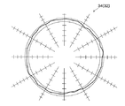
しかしながら、図10で示すように、ハブ132の外周面は、実際には平面視で略正三角形状に形成されてしまう場合がある。すなわち、例えば図9で示すように、リールギア142上に歯が無い領域が等間隔に3個形成され、その領域がゲート(ゲート跡G)とされるリール130では、金型内において、通常その領域を除いて(ゲートを避けて)リールプレート154が保持されるため、その領域を除いた部分とリールプレート154との間には溝部196が(3個)形成され、その領域とリールプレート154の間には溝部196が形成されない(連結部198が(3個)形成される)。
However, as shown in FIG. 10, the outer peripheral surface of the
したがって、金型から取り出して樹脂材が収縮したときに(冷却されたときに)、リールギア142の歯の無い領域、即ちゲート跡Gが形成されている領域では、溝部196が形成されていない(連結部198が形成されている)ため、リールプレート154にその収縮が抑制されてしまう。しかも、ゲート(ゲート跡G)付近では樹脂圧が高いため、他の部分よりも収縮率が小さい。よって、図10で示すように、ハブ132の外周面が歯の無い領域を頂点とする平面視略正三角形状に形成されてしまう。ハブ132の外周面が平面視略正三角形状に形成されると、記録テープの走行速度が均一にならないため、ドライブ装置側において読取エラーが発生するなどの懸念が生じる。
Therefore, when the resin material shrinks after being taken out from the mold (when cooled), the
そこで、本発明は、上記事情に鑑み、ハブの外周面の真円度を向上できるリールを得ることを目的とする。 In view of the above circumstances, an object of the present invention is to obtain a reel capable of improving the roundness of the outer peripheral surface of a hub.
上記の目的を達成するために、本発明に係る請求項1に記載のリールは、外周面に記録テープが巻回される有底円筒状の樹脂製のハブと、前記ハブの底部外面に形成され、ドライブ装置の駆動ギアが噛合可能なリールギアと、前記リールギアよりも径方向内側の前記ハブの底部外面にインサート成形によって設けられた金属製のリールプレートと、前記リールギア上に等間隔で形成された複数のゲート跡と、前記リールギアと前記リールプレートとの間で、かつ少なくとも前記ハブの中心と前記各ゲート跡とを結ぶ仮想直線上を含んで、周方向に等間隔で形成された複数の溝部と、を備えたことを特徴としている。 In order to achieve the above object, a reel according to claim 1 of the present invention is formed on a bottomed cylindrical resin hub around which a recording tape is wound on an outer peripheral surface and on the bottom outer surface of the hub. A reel gear capable of meshing with a drive gear of the drive device, a metal reel plate provided by insert molding on the outer surface of the bottom of the hub radially inward of the reel gear, and formed on the reel gear at equal intervals. A plurality of gate marks, and a plurality of lines formed at equal intervals in the circumferential direction, including at least a virtual straight line between the reel gear and the reel plate and connecting at least the center of the hub and the gate marks . It is characterized in that a groove.
請求項1に記載の発明では、リールギアとリールプレートとの間で周方向に等間隔に形成された複数の溝部が、少なくともハブの中心とゲート跡とを結ぶ仮想直線上の所定領域に形成されている(金型内では、少なくともハブの中心とゲートとを結ぶ仮想直線上の所定領域がリールプレートの保持部とされている)。したがって、金型から取り出して樹脂材が収縮したときに(冷却されたときに)、樹脂圧が高く収縮率の小さいゲート跡付近において(ゲート跡よりもハブの径方向内側において)、リールプレートが樹脂材の収縮を抑制しなくなる。よって、ハブの外周面における樹脂材の収縮が円周方向でほぼ均等に行われ、ハブの外周面の真円度を向上させることができる。 In the first aspect of the present invention, a plurality of groove portions formed at equal intervals in the circumferential direction between the reel gear and the reel plate are formed at least in a predetermined region on an imaginary straight line connecting the center of the hub and the gate mark. (In the mold, at least a predetermined region on an imaginary straight line connecting the center of the hub and the gate is used as a reel plate holding portion). Therefore, when the resin material shrinks after being taken out from the mold (when cooled), the reel plate is located near the gate mark where the resin pressure is high and the shrinkage rate is small (inside the gate mark in the radial direction of the hub). The shrinkage of the resin material is not suppressed. Therefore, the shrinkage of the resin material on the outer peripheral surface of the hub is performed substantially uniformly in the circumferential direction, and the roundness of the outer peripheral surface of the hub can be improved.
また、本発明に係る請求項2に記載のリールは、外周面に記録テープが巻回される有底円筒状の樹脂製のハブと、前記ハブの底部外面に形成され、ドライブ装置の駆動ギアが噛合可能なリールギアと、前記リールギアよりも径方向内側の前記ハブの底部外面にインサート成形によって設けられた金属製のリールプレートと、前記リールギア上に等間隔で形成された複数の歯の無い領域と、前記リールギアと前記リールプレートとの間で、かつ少なくとも前記ハブの中心と前記各領域とを結ぶ仮想直線上を含んで、周方向に等間隔で形成された複数の溝部と、を備えたことを特徴としている。 According to a second aspect of the present invention, there is provided a reel having a bottomed cylindrical resin hub around which a recording tape is wound on an outer peripheral surface, and a drive gear of a drive device. A reel gear that can mesh with each other, a metal reel plate that is formed by insert molding on the bottom outer surface of the hub radially inward of the reel gear, and a plurality of teeth-free regions formed at equal intervals on the reel gear And a plurality of grooves formed at equal intervals in the circumferential direction between the reel gear and the reel plate and including at least a virtual straight line connecting the center of the hub and each region . It is characterized by that.
請求項2に記載の発明では、リールギアとリールプレートとの間で周方向に等間隔に形成された複数の溝部が、少なくともハブの中心と歯の無い領域とを結ぶ仮想直線上の所定領域に形成されている(金型内では、少なくともハブの中心と歯の無い領域とを結ぶ仮想直線上の所定領域がリールプレートの保持部とされている)。ここで、歯の無い領域は、歯の有る領域とは樹脂材の収縮率が異なる。しかし、その歯の無い領域よりもハブの径方向内側には溝部が形成されているので、金型から取り出して樹脂材が収縮したときに(冷却されたときに)、歯の無い領域付近において(歯の無い領域よりもハブの径方向内側において)、リールプレートが樹脂材の収縮を抑制しなくなり、その歯の無い領域における樹脂材の収縮率を歯の有る領域における樹脂材の収縮率に近づけることができる。よって、ハブの外周面における樹脂材の収縮が円周方向でほぼ均等に行われ、ハブの外周面の真円度を向上させることができる。 In the invention according to claim 2, the plurality of grooves formed at equal intervals in the circumferential direction between the reel gear and the reel plate are at least a predetermined region on a virtual straight line connecting the center of the hub and the region without teeth. (In the mold, at least a predetermined area on an imaginary straight line connecting the center of the hub and the toothless area is a holding portion of the reel plate). Here, the shrinkage rate of the resin material is different in the region without teeth from the region with teeth. However, since the groove is formed on the inner side in the radial direction of the hub than the region without the teeth, when the resin material contracts after being taken out from the mold (when cooled), in the vicinity of the region without the teeth The reel plate does not suppress the shrinkage of the resin material (in the radial direction inside the hub from the region without the teeth), and the shrinkage rate of the resin material in the region without the teeth is changed to the shrinkage rate of the resin material in the region with the teeth. You can get closer. Therefore, the shrinkage of the resin material on the outer peripheral surface of the hub is performed substantially uniformly in the circumferential direction, and the roundness of the outer peripheral surface of the hub can be improved.
また、請求項3に記載のリールは、請求項1又は請求項2に記載のリールであって、前記溝部が、6個以上形成されていることを特徴としている。 A reel according to a third aspect is the reel according to the first or second aspect, wherein six or more of the groove portions are formed .
請求項3に記載の発明によれば、6個以上の溝部が、リールギアとリールプレートとの間で周方向に等間隔に形成されているので、金型から取り出して樹脂材が収縮したときに(冷却されたときに)、リールプレートが樹脂材の収縮を抑制する領域と抑制しない領域とが交互に各6個以上存在することになる。したがって、ハブの外周面における樹脂材の収縮が円周方向でほぼ均等に行われ、ハブの外周面の真円度を向上させることができる。 According to the invention described in claim 3, since the six or more grooves are formed at equal intervals in the circumferential direction between the reel gear and the reel plate, when the resin material contracts after being taken out from the mold When cooled (cooled), there will be six or more alternating regions where the reel plate suppresses shrinkage of the resin material and regions where it does not suppress. Therefore, the shrinkage of the resin material on the outer peripheral surface of the hub is performed substantially uniformly in the circumferential direction, and the roundness of the outer peripheral surface of the hub can be improved.
以上のように、本発明によれば、ハブの外周面の真円度を向上できるリールを提供することができる。 As described above, according to the present invention, it is possible to provide a reel capable of improving the roundness of the outer peripheral surface of the hub.
以下、本発明の最良な実施の形態について、図面に示す実施例を基に詳細に説明する。まず最初に、本実施形態に係るリール30を備えた記録テープカートリッジ10の概略構成について説明する。なお、説明の便宜上、図1で示すように、記録テープカートリッジ10のドライブ装置への装填方向を矢印Aで示し、それを記録テープカートリッジ10の前方向(前側)とする。そして、矢印A方向と直交する方向を矢印Bで示し、それを記録テープカートリッジ10の右方向(右側)とする。また、矢印A方向及び矢印B方向と直交する方向を矢印Cで示し、それを記録テープカートリッジ10及びリール30の上方向(上側)とする。
DESCRIPTION OF THE PREFERRED EMBODIMENTS The best mode for carrying out the present invention will be described below in detail based on the embodiments shown in the drawings. First, a schematic configuration of the
図1〜図3で示すように、記録テープカートリッジ10は、樹脂製のケース12を備えている。ケース12は、上ケース14と下ケース16とを接合して構成されている。具体的には、上ケース14は、平面視略矩形状の天板14Aの外縁に沿って略枠状の周壁14Bが立設されて構成されており、下ケース16は、天板14Aに略対応した形状の底板16Aの外縁に沿って略枠状の周壁16Bが立設されて構成されている。そして、ケース12は、周壁14Bの開口端と周壁16Bの開口端とを突き当てた状態で、超音波溶着やビス止め等によって上ケース14と下ケース16とが接合されて、略矩形箱状に形成されている。
As shown in FIGS. 1 to 3, the
このケース12には、ドライブ装置への装填方向先頭側の隅角部において、天板14A、周壁14B、底板16A、周壁16Bがそれぞれ切り欠かれて、その装填方向に対して傾斜した開口18が形成されている。また、底板16Aの略中央部には、底板16Aを貫通する円形状のギア開口20が設けられており、後述するリールギア42の露出用とされている。底板16Aにおけるギア開口20の縁部には、環状リブ22がケース12の内方へ向けて突設されており、後述するリール30の位置決め用及び防塵用とされている。
In this
また、ケース12の底板16Aの外面における前端近傍には、一対の位置決め穴24、26が開口している。一対の位置決め穴24、26は、底板16Aからケース12内方に立設された突部(図示省略)内に袋状に設けられ、矢印B方向における仮想線上で互いに離隔して配置されている。
A pair of
そして、開口18に近い側の位置決め穴24は、ドライブ装置の位置決めピン(図示省略)に外接する底面視略正方形状とされ、位置決め穴26は、上記仮想線に沿って長手で、かつ幅が位置決めピンの直径に対応する長穴とされている。したがって、記録テープカートリッジ10がドライブ装置に装填されて、位置決め穴24、26にそれぞれ位置決めピンが挿入されると、ドライブ装置内で水平方向(左右及び前後)に正確に位置決めされる構成である。
The
更に、底板16Aにおける位置決め穴24、26周りは、他の部分(意匠面)よりも平滑に仕上げられた基準面24A、26Aとされている。基準面24A、26Aは、位置決め穴24、26に位置決めピンが挿入されたときに、位置決めピン周りに設けられたドライブ装置の基準面(図示省略)に当接するようになっている。これにより、記録テープカートリッジ10のドライブ装置内における鉛直方向の位置決めがなされる構成である。
Furthermore, the periphery of the
また、ケース12内には、図2、図3で示すように、樹脂製のリール30(詳細は後述する)が1つだけ回転可能に収容される。このリール30には、磁気テープ等の記録テープTが巻装されており、図1で示すように、記録テープTの先端には、リーダー部材としてのリーダーブロック28が取り付けられている。リーダーブロック28は、記録テープカートリッジ10の不使用時には、ケース12の開口18の内側に収容保持されている。そして、この状態で、リーダーブロック28は、開口18を閉塞し、ケース12内への塵埃等の侵入を阻止している。
Further, as shown in FIGS. 2 and 3, only one resin reel 30 (details will be described later) is rotatably accommodated in the
また、リーダーブロック28は、その先端に係合凹部28Aが形成されており、ドライブ装置内で記録テープTを引き出す際には、係合凹部28Aに係合する引出手段(図示省略)によってケース12から抜き出されてドライブ装置の巻取リール(図示省略)に誘導されるようになっている。更に、リーダーブロック28は、その係合凹部28Aとは反対側の端面が円弧面28Bとされており、巻取リールのリールハブに嵌入されることにより、記録テープTを巻き取る巻取面の一部を構成するようになっている。
The
次に、リール30及び不使用時にリール30の回転を阻止する制動手段について説明する。図2〜図5で示すように、リール30は、その軸心部を構成するリールハブ32を備えている。リールハブ32は、上方に開口し、外周面に記録テープTが巻装される円筒部34と、円筒部34の下部を、後述する貫通孔50を除いて閉塞する底部36とを有する略有底円筒状に形成されている。そして、リールハブ32の底部36の外周縁部には、下フランジ38が同軸的かつ一体に径方向外側へ延設されている。
Next, the
また、リールハブ32の上端部には、上フランジ40が接合されるようになっており(図4、図5では省略されている)、本実施形態に係るリール30は、所謂2ピース構造とされている。すなわち、上フランジ40は、その外径が下フランジ38の外径と同径とされるとともに、軸心部に円筒部34の内径に対応する外径の短筒部40Aが設けられており、短筒部40Aが円筒部34の上端近傍に内嵌した状態で超音波溶着によってリールハブ32に同軸的に固着されている。これにより、リール30は、下フランジ38と上フランジ40との対向面間において、リールハブ32の円筒部34の外周面に記録テープTが巻回可能となる構成である。
An
また、リールハブ32の底部36の下面における外周縁部近傍には、全体としてリール30と同軸的な環状とされたリールギア42が形成されている。リールギア42は、ドライブ装置の回転シャフト100(後述)の先端に設けられた駆動ギア108と噛合可能とされている。このリールギア42は、その歯先が下フランジ38の下面よりも下方へ突出するとともに、歯底が下フランジ38の下面よりも上側に位置しており、かつ各歯の径方向外端部分が歯の高さ方向中央部から歯底にかけて下フランジ38に連続するテーパー部43によって連結されている。
In addition, a
なお、リールギア42上の所定位置には、成形用樹脂材の注入口とされたゲート跡Gが所定間隔を隔てて(等間隔に)複数個(図示のものは3個)形成されている。また、リールハブ32の底部36の上面(内面)における外周縁部近傍には、全体としてリール30と同軸的な環状とされた係合ギア44が形成されている。係合ギア44は、底部36の上面より若干隆起した環状の台座部46上に形成されており、後述する制動部材60の制動ギア66と噛合可能とされている。
A plurality of gate traces G (three in the figure) are formed at predetermined positions on the
また、リールハブ32の内周面、即ち係合ギア44よりも径方向外側の底部36の上面(内面)から円筒部34の内周面に亘って、リール30の軸線方向に沿った立リブ48が、等間隔で複数形成されている。この立リブ48の存在により、係合ギア44は、リールギア42よりも径方向内側に位置することになる。なお、立リブ48の詳細については、制動部材60と共に後述する。
Further, a standing
一方、リールハブ32の底部36の下面(外面)におけるリールギア42の径方向内側には、磁性材料で構成された環状金属板であるリールプレート54が、インサート成形により同軸的かつ一体的に設けられている。すなわち、リールプレート54には、小孔56が周方向に所定間隔を隔てて(等間隔に)複数個(図示のものは4個)形成されており、その小孔56の内周面には、下側の開口径が上側の開口径よりも大径となるような段差部(図示省略)が形成されている。したがって、このリールプレート54は、金型内にセットされた後、樹脂材が小孔56内に入り込み、その樹脂材が段差部の下面に回り込んで固化されることにより、底部36に固着される構成である。
On the other hand, on the radially inner side of the
また、リールハブ32の底部36における軸心部には、その底部36を貫通する貫通孔50が設けられている。また、底部36の上面からは、貫通孔50の縁部に沿って短円筒状のクラッチ用ボス部52が立設されている。このクラッチ用ボス部52については、後述するクラッチ部材84と共に説明する。また、リールプレート54の軸心部は透孔54Aとされており、透孔54Aの内径は貫通孔50の内径よりも僅かに小さく形成されている。
Further, a through
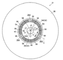
また、リールハブ32の底部36の下面(外面)において、リールギア42とリールプレート54との間の周方向には、等間隔に複数(6個以上)の溝部96が形成されている。すなわち、例えば図6で示すように、この溝部96は、リール30(リールハブ32)の回転中心Oと、リールハブ32及び下フランジ38を一体成形する樹脂材の注入口とされたゲート跡Gとを結ぶ仮想直線K上の所定領域(歯の無い部分の幅)Eを3個含み、中心角θが、例えばθ=40度とされて等間隔に6個形成されている。
A plurality (six or more) of
なお、この溝部96の数量が6個以上とされているのは、リールハブ32の外周面を真円に近づけるためである。つまり、リールハブ32の外周面を真円に近づけるためには、溝部96を等間隔に6個以上形成し、平面視で略正六角形以上にすることが望ましい。また、この溝部96は、図示しない金型内においては、リールプレート54を保持する保持部となる。したがって、保持部が存在していない領域には、樹脂材が流れ込み、その部分がリールギア42とリールプレート54との間を連結するような連結部98とされている。
The reason why the number of the
また、リール30は、ケース12に収容されて、不使用時には環状リブ22上に載置されるようになっている。具体的には、リール30は、底部36におけるテーパー部43の径方向外側部分(下フランジ38の内周縁部近傍)が環状リブ22の上端面に当接するようになっており、環状リブ22の上端内周縁部がテーパー部43に対応したテーパー面22Aとされることで、径方向の移動が規制されている。そして、そこからの塵埃等の侵入を抑止する構成になっている。
The
この状態で、リール30は、全体としてケース12内に位置して、リールギア42、リールプレート54をギア開口20から露出させている(図1(B)参照)。すなわち、リールギア42は、底板16Aの外面(下面)から突出することなく、ギア開口20からケース12外に臨んでいる。また、リールプレート54の透孔54Aを通じて貫通孔50がギア開口20に臨んでいる。
In this state, the
これにより、ケース12の外部よりリール30の操作、即ちチャッキング(保持)及び回転駆動が可能とされている。また、この状態で、リール30のリールハブ32の上端部内周面側には、天板14Aから立設された環状の規制リブ58が入り込んでいる。規制リブ58は、その外周面を上フランジ40の短筒部40Aの内周面に近接させており、ケース12内におけるリール30のガタつきを抑止する構成である。
As a result, the
また、記録テープカートリッジ10は、不使用時にリール30の回転を阻止するための制動手段としての制動部材60を備えている。図4、図5で示すように、制動部材60は基部62を有しており、基部62は、短円筒状に形成された筒部62Aと、筒部62Aの上端を閉塞する円板部62Bとで、下方に開口した略有底円筒状に形成されている。そして、基部62(筒部62A)の外周部における軸線方向中間部からは、環状に形成されたリング部64が全周に亘り径方向外側に延設されている。
Further, the
リング部64の下面には、全周に亘り制動ギア66が設けられている。すなわち、制動ギア66は、全体として環状に形成されており、リール30の係合ギア44と噛合可能に構成されている。また、リング部64の上面には、その外周縁部に沿って環状の補強リブ68が立設されており、リング部64(制動ギア66)の剛性が確保されるようになっている。また、基部62の円板部62Bの下面(筒部62Aの径方向内側)における軸心部からは、摺接突部70が突設されている。摺接突部70は、その先端部が略球面状に形成されており、後述するクラッチ部材84と略点接触するようになっている。
A
一方、円板部62Bの上面からは、内部に平面視略十字状に形成された挿入溝72Aが形成された十字突起72が立設されている。また、円板部62Bには、これを板厚方向に貫通する貫通孔74が穿設されている。貫通孔74は、平面視で十字状に形成された挿入溝72Aにおける軸心部(交差部)を除く径方向外側部分と連通するように、4分割されてそれぞれ矩形状に形成されている。
On the other hand, a
これにより、各貫通孔74は、それぞれ摺接突部70の径方向外側に隣接して位置し、筒部62A内部に開口している。また、基部62の上端外周縁部には環状のリブ76が立設されており、リブ76と十字突起72との間の円板部62B上面が、後述する圧縮コイルスプリング82の一端部が当接するバネ受面78とされている。
As a result, each through
このような構成とされた制動部材60は、リールハブ32内に、上下方向(リール30の軸線方向)に移動可能に、かつ略同軸的に挿設されている。すなわち、制動部材60は、上下方向に移動することで、その制動ギア66をリール30(リールハブ32)の係合ギア44と噛合する位置(回転ロック位置)と、その噛合を解除する位置(回転許容位置)とを取り得るようになっている。
The braking
また、制動部材60の十字突起72の挿入溝72Aには、ケース12の天板14Aから下方へ突設された十字リブ80が入り込むようになっている。十字リブ80は、2つの薄板片を互いに直交するように交差させたような形状とされた回り止め形状とされ、十字突起72(挿入溝72Aの溝壁)と係合することで、制動部材60のケース12に対する回転を阻止する構成である。
Further, a
したがって、制動部材60は、その制動ギア66をリールハブ32の係合ギア44と噛合させることで、リール30の回転を阻止できる。なお、十字リブ80は、制動部材60の上下方向の全移動ストロークに亘って挿入溝72Aに入り込んだ状態が維持されるようになっており、制動部材60の移動方向を上下方向にガイドする機能も果たす構成である。また、制動部材60は、回転ロック位置に位置するときには、リール30の立リブ48によって径方向の移動が規制され、回転許容位置に位置するときには、リール30と共に回転する立リブ48と干渉しないように構成されている。
Therefore, the braking
つまり、立リブ48は、回転ロック位置に位置する制動部材60のリング部64の外周縁部(補強リブ68)に近接して位置するようになっており、かつ回転許容位置に位置する制動部材60の外周縁部(補強リブ68)との間隔が所定値以上となるように、その上部が切り欠かれている。これにより、リール30は、ケース12に直接的に移動規制されるのみならず、その重心位置近傍において、制動部材60を介してケース12に対する径方向の移動が規制されるようになっており、縦置きされた(リール30の軸線を水平方向とする)ドライブ装置にも安定して装填可能とされている。
That is, the standing
更に、十字リブ80の下端部には、制動部材60の各貫通孔74に挿通可能な突片80Aが延設されている。各突片80Aは、制動部材60が回転ロック位置に位置するときには挿入溝72A内に位置し、制動部材60が解除位置に位置するときには、それぞれ貫通孔74に入り込んで、円板部62Bの下面から突出する(貫通孔74を貫通する)ようになっている。このように各突片80Aが延設されることにより、十字リブ80は、制動部材60のケース12に対する回転を阻止するだけではなく、制動部材60との係合量(挿入深さ)を増加させることができ、制動部材60のケース12に対する傾きを抑制することができる。
Further, a projecting
また、制動部材60のバネ受面78と天板14Aとの間には、広義には付勢手段として把握される圧縮コイルスプリング82が配設されている。圧縮コイルスプリング82は、その一端部がバネ受面78に当接するとともに、他端部が天板14Aに当接しており、この他端部は天板14Aにおける十字リブ80の径方向外側から突設された環状壁部83の内側に位置して径方向に位置ズレしないようになっている。
A
そして、この圧縮コイルスプリング82の付勢力により、制動部材60が下方に付勢されて、通常は制動ギア66を係合ギア44に噛合させて、リール30の不用意な回転を確実に防止している(制動部材60を回転ロック位置に位置させている)。また、この付勢力により、リール30も下方に付勢され、環状リブ22に当接されて、ケース12内でガタつかないようになっている。
The braking
また、記録テープカートリッジ10は、制動部材60によるリール30のロック状態を解除するときに外部から操作される解除部材としてのクラッチ部材84を備えている。クラッチ部材84は、リール30の底部36と制動部材60との間に配設されている。図4、図5で示すように、クラッチ部材84は、略円柱状に形成されたクラッチ本体86を有している。クラッチ本体86は、その外径がリールプレート54の透孔54Aとほぼ同一に、即ちクラッチ用ボス部52の内径と一致する貫通孔50の内径よりも若干小さく形成されている。
Further, the
クラッチ本体86は、その平坦な軸心部上端面が制動部材60の摺接突部70と常に当接する摺接面86Aとされている。また、クラッチ本体86における下方に開口して設けられた肉抜穴86B周りの平坦な下端面が押圧操作面86Cとされている。そして、クラッチ部材84は、その押圧操作面86Cが押圧されると、圧縮コイルスプリング82の付勢力に抗して上方へ移動し、制動部材60を回転許容位置へ移動させる構成とされている。
The clutch
また、このクラッチ部材84は、クラッチ本体86の外周面よりも径方向外側に張り出した回転規制リブ88を備えている。回転規制リブ88は、クラッチ本体86の周方向に等間隔で複数(図示のものは3つ)設けられ、各回転規制リブ88は平面視で放射状に配置されている。また、各回転規制リブ88は、クラッチ本体86の摺接面86A周りの上端面と、その上端面近傍の外周面とに跨る(それぞれに連続する)ように、摺接面86Aよりも上方に突出している。
Further, the
各回転規制リブ88は、それぞれクラッチ用ボス部52の内周面に凹設された回転規制溝90に入り込むようになっている。すなわち、各回転規制溝90は、クラッチ用ボス部52の周方向に等間隔で3つ設けられている。各回転規制溝90は、クラッチ用ボス部52の上端で上方に開口している。これにより、クラッチ部材84は、その回転規制リブ88においてクラッチ用ボス部52の回転規制溝90にガイドされつつ上下方向の移動が可能とされている。
Each
また、各回転規制リブ88は、クラッチ部材84が上方に移動して制動部材60を回転許容位置に位置させるときにも、クラッチ用ボス部52の回転規制溝90に入り込んだ状態を維持するようになっている。これにより、クラッチ部材84は、リール30に対する相対回転不能、即ち常にリール30と一体に回転する構成とされている。
Further, each
また更に、各回転規制溝90がクラッチ用ボス部52の下端部において閉塞されていることから、回転規制リブ88と回転規制溝90とによってクラッチ部材84のリールハブ32からの脱落を阻止することもできるが、このクラッチ部材84は、回転規制リブ88とは別に、そのリールハブ32からの脱落を阻止する着座リブ92を備えている。
Furthermore, since each
着座リブ92は、クラッチ本体86の周方向に等間隔で複数(図示のものは各回転規制リブ88間の周方向中間部に計3つ)設けられている。各着座リブ92は、回転規制リブ88と同様に、クラッチ本体86の摺接面86A周りの上端面と、その上端面近傍の外周面とに跨るように、上方及び径方向外方に突出しており、平面視で放射状に配置されている。
A plurality of
各着座リブ92は、それぞれクラッチ用ボス部52の内周面に凹設されたストッパー溝94に入り込むようになっている。すなわち、各ストッパー溝94は、クラッチ用ボス部52の周方向に等間隔で、各回転規制溝90の周方向中間部に設けられている。各ストッパー溝94は、クラッチ用ボス部52の上端で上方に開口しており、その下端部を閉塞する底部上面がストッパー面94Aとされている。各着座リブ92は、制動部材60が回転ロック位置にあるときには、その下端面がストッパー面94Aに当接(着座)するようになっている。
Each of the
また、図2、図3で示すように、回転シャフト100は回転軸102を備えており、回転軸102の上端には、円板状の回転テーブル104が同軸的かつ一体的に設けられている。回転テーブル104の上面で、かつ外周縁部には、記録テープカートリッジ10のリールギア42と噛合可能な駆動ギア108が環状に形成されている。また、回転テーブル104の上面で、駆動ギア108の径方向内側には、略円板状に形成されたマグネット106が同軸的に配設されており、回転テーブル104の軸心部には、クラッチ部材84の押圧操作面86Cに当接する解除突部110が形成されている。
As shown in FIGS. 2 and 3, the
次に、以上のような構成のリール30及び制動手段を備えた記録テープカートリッジ10の作用について説明する。記録テープカートリッジ10では、不使用時には、圧縮コイルスプリング82の付勢力によって、制動部材60が回転ロック位置に位置して制動ギア66を係合ギア44に噛合させている。このため、リール30は、ケース12に対する回転が阻止されている。このとき、リール30のリールギア42がギア開口20から露出するとともに、クラッチ部材84のクラッチ本体86が貫通孔50及び透孔54Aに挿通されてギア開口20に臨んでいる。
Next, the operation of the
一方、記録テープTを使用する際には、記録テープカートリッジ10を矢印A方向に沿ってドライブ装置のバケット(図示省略)へ装填する。そして、記録テープカートリッジ10がバケットに所定深さまで装填されると、バケットは下降し、ドライブ装置の回転シャフト100がケース12のギア開口20に向って相対的に接近(上方へ移動)してリール30を保持する。具体的には、回転シャフト100は、マグネット106によって非接触でリールプレート54を吸着保持しつつ、その駆動ギア108をリールギア42と噛合させる。
On the other hand, when the recording tape T is used, the
このリールギア42と駆動ギア108との噛合、即ちケース12に対する回転シャフト100の軸方向近接側の相対移動に伴って、回転シャフト100の解除突部110がクラッチ部材84の押圧操作面86Cに当接し、圧縮コイルスプリング82の付勢力に抗してクラッチ部材84を上方に押し上げる。これにより、摺接突部70においてクラッチ部材84に当接している制動部材60も上方に移動し、制動ギア66と係合ギア44との噛合が解除されるとともに、リール30に対する相対的な回転許容位置へ移動する。
As the
すなわち、回転シャフト100が上方へ相対移動すると、圧縮コイルスプリング82の付勢力に抗して、リール30がクラッチ部材84、制動部材60と共に(相対位置を変化させないまま)上方に持ち上げられ、制動部材60が(ケース12に対する)回転許容位置へ達するとともに、下フランジ38が環状リブ22(テーパー面22A)から離隔する。これにより、リール30は、ケース12内で浮上して、ケース12の内面と非接触状態で回転可能となる。
That is, when the
また、このとき、バケット、即ち記録テープカートリッジ10のドライブ装置内での下降によって、ケース12の各位置決め穴24、26にそれぞれドライブ装置の位置決めピンが入り込むとともに、ケース12の各基準面24A、26Aにドライブ装置の基準面が当接する。これにより、記録テープカートリッジ10は、ドライブ装置に対する水平方向及び鉛直方向が位置決めされる。すると、ドライブ装置の引出手段が、リーダーブロック28の係合凹部28Aに係合しつつ、リーダーブロック28をケース12から抜き出してドライブ装置の巻取リールに誘導する。
At this time, as the bucket, that is, the
そして、リーダーブロック28は、巻取リールのリールハブに嵌入されて、その円弧面28Bが記録テープTを巻き取る巻取面の一部を構成する。この状態で、リーダーブロック28が巻取リールと一体に回転すると、記録テープTが巻取リールのリールハブに巻き取られつつ、開口18を通じてケース12から引き出される。なお、このとき、記録テープカートリッジ10のリール30は、リールギア42に噛合する駆動ギア108によって伝達される回転シャフト100の回転力によって、巻取リールと同期して回転する。
The
そして、ドライブ装置の所定のテープ経路に沿って配設された記録再生ヘッド(図示省略)により、記録テープTへの情報の記録、又は記録テープTに記録された情報の再生がなされる。なお、このとき、ケース12に対して回転不能である制動部材60の摺接突部70は、リール30と共にケース12に対して回転するクラッチ部材84の摺接面86Aと摺接している。つまり、クラッチ部材84は、リールギア42が駆動ギア108と噛合している状態では、その押圧操作面86Cにおける解除突部110との当接状態が維持されて、制動部材60を回転許容位置に保持する構成である。
Then, information is recorded on the recording tape T or information recorded on the recording tape T is reproduced by a recording / reproducing head (not shown) arranged along a predetermined tape path of the drive device. At this time, the sliding
そして、リール30の回転時には、リール30と一体に回転するクラッチ部材84とリール30を駆動する回転シャフト100との間には相対回転がなく、押圧操作面86Cと解除突部110とは互いに摺接することがない構成であり、クラッチ部材84の摺接面86Aと、ケース12に対して回転不能な制動部材60の摺接突部70とが互いに摺接する構成になっている。このように、回転軸102とクラッチ部材84との間には相対回転がないため、解除突部110や押圧操作面86Cが摩耗されるような不具合はない。
When the
一方、記録テープTへの情報の記録、又は記録テープTに記録された情報の再生が終了すると、記録テープTがリール30に巻き戻されてリーダーブロック28がケース12の開口18近傍に保持される。そして、記録テープカートリッジ10が装填されたバケットが上昇する。すると、リールギア42と駆動ギア108との噛合が解除されるとともに、解除突部110とクラッチ部材84の押圧操作面86Cとの当接が解除され、クラッチ部材84が圧縮コイルスプリング82の付勢力によって制動部材60と共に(当接状態を維持しつつ)下方へ移動する。
On the other hand, when the recording of information on the recording tape T or the reproduction of the information recorded on the recording tape T is completed, the recording tape T is rewound onto the
これにより、クラッチ部材84の各着座リブ92がストッパー面94Aに当接するとともに、制動部材60の制動ギア66が係合ギア44と噛合する。すなわち、制動部材60がケース12に対してリール30の回転を阻止する回転ロック位置へ復帰する。また、制動部材60とクラッチ部材84とが圧縮コイルスプリング82の付勢力によって移動する動作に伴って、リール30も下方へ移動して、その下フランジ38を環状リブ22に当接させつつ、リールギア42をギア開口20から露出させる初期状態に復帰する。この状態で、記録テープカートリッジ10がドライブ装置(バケット)から排出される。
As a result, each
次に、本実施形態に係るリール30の作用について詳細に説明する。図6で示すように、このリール30のリールハブ32の底部36下面(外面)において、リールギア42とリールプレート54との間の周方向には、溝部96が等間隔に(例えば中心角θ=40度とされて)6個形成されている。
Next, the operation of the
そして特に、リール30(リールハブ32)の回転中心Oとゲート跡Gとを結ぶ仮想直線K上の所定領域(歯の無い部分の幅)Eには、その溝部96が必ず(少なくとも)形成されるように構成されている。換言すれば、金型内においては、少なくともリール30(リールハブ32)の回転中心Oとゲート跡Gとを結ぶ仮想直線K上の所定領域Eが、リールプレート54の保持部とされている。
In particular, the
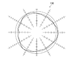
したがって、金型から取り出して樹脂材が収縮したときに(冷却されたときに)、樹脂圧が高く収縮率の小さいゲート跡G付近、特にゲート跡Gよりもリールハブ32の径方向内側において、リールプレート54が樹脂材の収縮を抑制しなくなるので、リールハブ32(円筒部34)の外周面における樹脂材の収縮が円周方向でほぼ均等に行われるようになる。よって、図7で示すように、リールハブ32(円筒部34)の外周面は、平面視略正六角形状に形成され、その真円度を向上させる(改善する)ことができる。
Accordingly, when the resin material shrinks after being taken out from the mold (when cooled), the reel is located near the gate mark G where the resin pressure is high and the shrinkage rate is small, particularly inside the
また、図8で示すリール31の場合も同様である。なお、このリール31において、リール30と同等な部位には同じ符号を付して詳細な説明は省略する。このリール31では、ゲート(ゲート跡G)がリールハブ32の回転中心Oに設けられ、リールギア42上に図示しない解除部材の脚部が挿通される底面視略「D」字状の貫通孔36Aが等間隔に3個形成されている。
The same applies to the
このような構成のリール31の場合、その貫通孔36Aが形成された歯の無い領域Eの樹脂材の収縮率は、歯の有る領域の樹脂材の収縮率と異なる。そのため、図10で示す従来のリール130のように、リールハブ132の外周面は、平面視略正三角形状に形成されるおそれがある。
In the case of the
しかし、リール31(リールハブ32)の回転中心Oと貫通孔36Aとを結ぶ仮想直線K上の所定領域(歯の無い部分の幅)Eには、その溝部96が必ず(少なくとも)形成されるように構成されている。換言すれば、金型内においては、少なくともリール30(リールハブ32)の回転中心Oと貫通孔36Aとを結ぶ仮想直線K上の所定領域Eが、リールプレート54の保持部とされている。
However, the
したがって、金型から取り出して樹脂材が収縮したときに(冷却されたときに)、歯の無い領域E(貫通孔36A)付近、特に歯の無い領域E(貫通孔36A)よりも径方向内側において、リールプレート54が樹脂材の収縮を抑制しなくなり、その歯の無い領域Eにおける樹脂材の収縮率を、歯の有る領域における樹脂材の収縮率に近づけることができるので、リールハブ32(円筒部34)の外周面における樹脂材の収縮が円周方向でほぼ均等に行われるようになる。よって、この場合も、図7で示すように、リールハブ32(円筒部34)の外周面は、平面視略正六角形状に形成され、その真円度を向上させる(改善する)ことができる。
Accordingly, when the resin material is taken out from the mold and contracted (cooled), the vicinity of the toothless region E (through
以上、何れにしても、リールギア42とリールプレート54との間の周方向に、6個以上(少なくとも6個)の溝部96を等間隔に形成すれば、金型から取り出して樹脂材が収縮したときに(冷却されたときに)、リールプレート54が樹脂材の収縮を抑制する領域(連結部98が形成されている領域)と抑制しない領域とが交互に各6個以上存在することになるため、リールハブ32(円筒部34)の外周面を平面視略正六角形状以上に形成することができ、リールハブ32(円筒部34)の外周面における樹脂材の収縮を円周方向においてほぼ均等にすることができる。
In any case, if six or more (at least six)
したがって、歯の無い領域Eが形成されていないリールギア42を備えたリール(図示省略)の場合も同様に適用可能であり、その場合も、リールハブ32(円筒部34)の外周面の真円度を向上させる(改善する)ことができる。また、溝部96の数量は、周方向に等間隔に6個以上形成することが望ましいが、真円度を向上させる観点からは、リールギア42上にゲート跡G又は貫通孔36A等の歯の無い領域Eが複数形成されている場合には、その複数形成されているゲート跡G又は貫通孔36A(歯の無い領域E)の2以上の整数倍とする方が、より望ましい。
Therefore, the present invention can be similarly applied to a reel (not shown) provided with a
また、上記実施例では、下フランジ38がリールハブ32と一体成形されたリール30に本発明を適用した例を示したが、本発明はこれに限定されず、例えば上フランジ40がリールハブ32と一体に形成されたリール(図示省略)に本発明を適用してもよい。要するに、射出成形時の樹脂材の収縮アンバランスにより、リールハブ32(円筒部34)の外周面(外径)が、平面視で真円から乖離する別の形態のリール全てに本発明は適用可能である。
In the above embodiment, the present invention is applied to the
また、上記実施例では、記録テープカートリッジ10が、リーダー部材としてリーダーブロック28を有する構成とされているが、本発明はこれに限定されず、例えば記録テープTの先端にリーダー部材として小円柱状のリーダピンが取り付けられた構成としてもよく、更には開口18を開閉する遮蔽部材(所定の直線又は円弧に沿って移動するスライドドア等)を有する構成としてもよい。
In the above embodiment, the
また、上記実施例では、リール30が記録テープカートリッジ10に適用された例を示したが、本発明はこれに限定されず、例えば送出用、巻取用の2つのリールをケース内に収容した記録テープカセット(図示省略)に本発明を適用してもよい。この場合、少なくとも1つのリールに本発明が適用されればよいことは言うまでもない。また、ドライブ装置の巻取リール等に本発明を適用することも可能である。
In the above embodiment, the
更に、上記実施例では、磁気テープ等の記録テープTを用いた構成としたが、本発明はこれに限定されず、記録テープTとしては、情報の記録及び記録した情報の再生が可能な長尺テープ状の情報記録再生媒体として把握されるものであれば足り、本発明に係るリール30が、如何なる記録再生方式の記録テープTにも適用可能であることは言うまでもない。
Further, in the above embodiment, the recording tape T such as a magnetic tape is used. However, the present invention is not limited to this, and the recording tape T has a length capable of recording information and reproducing the recorded information. Needless to say, the
10 記録テープカートリッジ
12 ケース
30 リール
32 リールハブ(ハブ)
34 円筒部
36 底部
38 下フランジ
40 上フランジ
42 リールギア
44 係合ギア
54 リールプレート
60 制動部材
84 クラッチ部材
96 溝部
98 連結部
G ゲート跡
T 記録テープ
10
34
Claims (3)
前記ハブの底部外面に形成され、ドライブ装置の駆動ギアが噛合可能なリールギアと、
前記リールギアよりも径方向内側の前記ハブの底部外面にインサート成形によって設けられた金属製のリールプレートと、
前記リールギア上に等間隔で形成された複数のゲート跡と、
前記リールギアと前記リールプレートとの間で、かつ少なくとも前記ハブの中心と前記各ゲート跡とを結ぶ仮想直線上を含んで、周方向に等間隔で形成された複数の溝部と、
を備えたことを特徴とするリール。 A bottomed cylindrical resin hub around which a recording tape is wound on the outer peripheral surface;
A reel gear formed on the outer surface of the bottom of the hub and capable of meshing with a drive gear of a drive device;
A metal reel plate provided by insert molding on the bottom outer surface of the hub radially inward of the reel gear;
A plurality of gate marks formed at equal intervals on the reel gear;
A plurality of grooves formed at equal intervals in the circumferential direction between the reel gear and the reel plate and including at least a virtual straight line connecting the center of the hub and the gate traces ;
Reel, characterized in that it comprises a.
前記ハブの底部外面に形成され、ドライブ装置の駆動ギアが噛合可能なリールギアと、
前記リールギアよりも径方向内側の前記ハブの底部外面にインサート成形によって設けられた金属製のリールプレートと、
前記リールギア上に等間隔で形成された複数の歯の無い領域と、
前記リールギアと前記リールプレートとの間で、かつ少なくとも前記ハブの中心と前記各領域とを結ぶ仮想直線上を含んで、周方向に等間隔で形成された複数の溝部と、
を備えたことを特徴とするリール。 A bottomed cylindrical resin hub around which a recording tape is wound on the outer peripheral surface;
A reel gear formed on the outer surface of the bottom of the hub and capable of meshing with a drive gear of a drive device;
A metal reel plate provided by insert molding on the bottom outer surface of the hub radially inward of the reel gear;
A plurality of toothless regions formed at equal intervals on the reel gear;
A plurality of grooves formed at equal intervals in the circumferential direction between the reel gear and the reel plate and including at least a virtual straight line connecting the center of the hub and each region ;
Reel, characterized in that it comprises a.
Priority Applications (2)
| Application Number | Priority Date | Filing Date | Title |
|---|---|---|---|
| JP2007230626A JP4805232B2 (en) | 2007-09-05 | 2007-09-05 | reel |
| US12/223,000 US7600710B2 (en) | 2007-09-05 | 2008-08-21 | Reel |
Applications Claiming Priority (1)
| Application Number | Priority Date | Filing Date | Title |
|---|---|---|---|
| JP2007230626A JP4805232B2 (en) | 2007-09-05 | 2007-09-05 | reel |
Publications (2)
| Publication Number | Publication Date |
|---|---|
| JP2009064506A JP2009064506A (en) | 2009-03-26 |
| JP4805232B2 true JP4805232B2 (en) | 2011-11-02 |
Family
ID=40405863
Family Applications (1)
| Application Number | Title | Priority Date | Filing Date |
|---|---|---|---|
| JP2007230626A Active JP4805232B2 (en) | 2007-09-05 | 2007-09-05 | reel |
Country Status (2)
| Country | Link |
|---|---|
| US (1) | US7600710B2 (en) |
| JP (1) | JP4805232B2 (en) |
Families Citing this family (9)
| Publication number | Priority date | Publication date | Assignee | Title |
|---|---|---|---|---|
| JP2007293984A (en) * | 2006-04-24 | 2007-11-08 | Fujifilm Corp | Reel and metal mold for forming this reel |
| JP4367785B2 (en) * | 2006-12-12 | 2009-11-18 | 日立マクセル株式会社 | Single reel type tape cartridge |
| JP4805232B2 (en) * | 2007-09-05 | 2011-11-02 | 富士フイルム株式会社 | reel |
| US8123158B2 (en) * | 2008-07-28 | 2012-02-28 | Fujifilm Corporation | Reel and recording tape cartridge |
| JP5377139B2 (en) * | 2008-07-28 | 2013-12-25 | 富士フイルム株式会社 | Reel and recording tape cartridge |
| JP5795509B2 (en) * | 2011-08-30 | 2015-10-14 | 日立マクセル株式会社 | Tape cartridge |
| JP6153910B2 (en) * | 2014-09-19 | 2017-06-28 | 富士フイルム株式会社 | Metal plate and recording tape cartridge |
| JP6363546B2 (en) | 2015-03-27 | 2018-07-25 | 富士フイルム株式会社 | Reel manufacturing method |
| JP6317286B2 (en) | 2015-03-27 | 2018-04-25 | 富士フイルム株式会社 | Reel, reel component manufacturing method, and reel manufacturing method |
Family Cites Families (14)
| Publication number | Priority date | Publication date | Assignee | Title |
|---|---|---|---|---|
| JPH0519903Y2 (en) * | 1986-04-17 | 1993-05-25 | ||
| JP2693818B2 (en) * | 1989-05-18 | 1997-12-24 | 株式会社日立製作所 | Information disk and manufacturing method thereof |
| JP4094131B2 (en) * | 1998-07-31 | 2008-06-04 | 富士フイルム株式会社 | Magnetic tape cartridge reel |
| EP1173847A1 (en) * | 2000-02-24 | 2002-01-23 | Jabil Circuit Cayman L.P. | Recording and/or reproducing apparatus including a reel disc having a magnetic circuit element and drive teeth realized by insert-molding |
| US6676055B1 (en) * | 2002-11-22 | 2004-01-13 | Imation Corp. | Tape reel assembly with tape drive clutch engagement feature |
| JP2005196876A (en) * | 2004-01-07 | 2005-07-21 | Fuji Photo Film Co Ltd | Recording tape cartridge |
| JP2005251314A (en) * | 2004-03-05 | 2005-09-15 | Fuji Photo Film Co Ltd | Magnetic tape cartridge |
| JP4367765B2 (en) * | 2004-03-17 | 2009-11-18 | 日立マクセル株式会社 | Tape reel for magnetic tape cartridge |
| JP2006004459A (en) * | 2004-06-15 | 2006-01-05 | Tdk Corp | Cartridge case and information recording medium |
| JP2006018868A (en) * | 2004-06-30 | 2006-01-19 | Tdk Corp | Cartridge case and information recording medium |
| JP4266208B2 (en) * | 2005-03-11 | 2009-05-20 | 富士フイルム株式会社 | Magnetic tape cartridge |
| JP2007080434A (en) * | 2005-09-15 | 2007-03-29 | Fujifilm Corp | Reel, recording tape cartridge, and mold |
| US7334751B2 (en) * | 2006-02-27 | 2008-02-26 | Tdk Corporation | Tape reel, cartridge case, and information recording medium |
| JP4805232B2 (en) * | 2007-09-05 | 2011-11-02 | 富士フイルム株式会社 | reel |
-
2007
- 2007-09-05 JP JP2007230626A patent/JP4805232B2/en active Active
-
2008
- 2008-08-21 US US12/223,000 patent/US7600710B2/en active Active
Also Published As
| Publication number | Publication date |
|---|---|
| JP2009064506A (en) | 2009-03-26 |
| US20090057463A1 (en) | 2009-03-05 |
| US7600710B2 (en) | 2009-10-13 |
Similar Documents
| Publication | Publication Date | Title |
|---|---|---|
| JP4805232B2 (en) | reel | |
| JP4833171B2 (en) | reel | |
| JP2008097721A (en) | Reel | |
| JP5496646B2 (en) | Reel and recording tape cartridge | |
| JP4837450B2 (en) | Recording tape cartridge | |
| JP4712606B2 (en) | Reel and reel manufacturing method | |
| JP4800103B2 (en) | reel | |
| JP2004253078A (en) | Recording tape cartridge | |
| JP4767926B2 (en) | reel | |
| JP4133590B2 (en) | Drive device | |
| JP4362077B2 (en) | Recording tape cartridge | |
| JP4879850B2 (en) | Recording tape cartridge | |
| JP4879855B2 (en) | reel | |
| JP2008102979A (en) | Reel | |
| US20070278337A1 (en) | Reel and mold for molding the reel | |
| JP4795192B2 (en) | reel | |
| US20100320643A1 (en) | Reel | |
| JP5127958B2 (en) | reel | |
| JP2005085382A (en) | Recording tape cartridge | |
| JP2008097744A (en) | Reel | |
| JP2007328835A (en) | Recording tape cartridge | |
| JP2009080900A (en) | Reel | |
| JP2006228350A (en) | Recording tape cartridge | |
| JP2007317336A (en) | Reel | |
| JP2008112540A (en) | Reel |
Legal Events
| Date | Code | Title | Description |
|---|---|---|---|
| A621 | Written request for application examination |
Free format text: JAPANESE INTERMEDIATE CODE: A621 Effective date: 20100202 |
|
| A977 | Report on retrieval |
Free format text: JAPANESE INTERMEDIATE CODE: A971007 Effective date: 20110407 |
|
| A131 | Notification of reasons for refusal |
Free format text: JAPANESE INTERMEDIATE CODE: A131 Effective date: 20110524 |
|
| A521 | Request for written amendment filed |
Free format text: JAPANESE INTERMEDIATE CODE: A523 Effective date: 20110627 |
|
| TRDD | Decision of grant or rejection written | ||
| A01 | Written decision to grant a patent or to grant a registration (utility model) |
Free format text: JAPANESE INTERMEDIATE CODE: A01 Effective date: 20110719 |
|
| A01 | Written decision to grant a patent or to grant a registration (utility model) |
Free format text: JAPANESE INTERMEDIATE CODE: A01 |
|
| A61 | First payment of annual fees (during grant procedure) |
Free format text: JAPANESE INTERMEDIATE CODE: A61 Effective date: 20110810 |
|
| R150 | Certificate of patent or registration of utility model |
Ref document number: 4805232 Country of ref document: JP Free format text: JAPANESE INTERMEDIATE CODE: R150 Free format text: JAPANESE INTERMEDIATE CODE: R150 |
|
| FPAY | Renewal fee payment (event date is renewal date of database) |
Free format text: PAYMENT UNTIL: 20140819 Year of fee payment: 3 |
|
| R250 | Receipt of annual fees |
Free format text: JAPANESE INTERMEDIATE CODE: R250 |
|
| R250 | Receipt of annual fees |
Free format text: JAPANESE INTERMEDIATE CODE: R250 |
|
| R250 | Receipt of annual fees |
Free format text: JAPANESE INTERMEDIATE CODE: R250 |
|
| R250 | Receipt of annual fees |
Free format text: JAPANESE INTERMEDIATE CODE: R250 |
|
| R250 | Receipt of annual fees |
Free format text: JAPANESE INTERMEDIATE CODE: R250 |
|
| R250 | Receipt of annual fees |
Free format text: JAPANESE INTERMEDIATE CODE: R250 |
|
| R250 | Receipt of annual fees |
Free format text: JAPANESE INTERMEDIATE CODE: R250 |
|
| R250 | Receipt of annual fees |
Free format text: JAPANESE INTERMEDIATE CODE: R250 |
|
| R250 | Receipt of annual fees |
Free format text: JAPANESE INTERMEDIATE CODE: R250 |
|
| R250 | Receipt of annual fees |
Free format text: JAPANESE INTERMEDIATE CODE: R250 |